Honeywell has launched the Honeywell Alternative Navigation Architecture (HANA) — a software-based solution designed to ensure resilient navigation for crewed and uncrewed aircraft, as well as military surface vehicles, in environments where GNSS signals are degraded, jammed or spoofed.
“Due to the proliferation of low-cost tools, the number of jamming, spoofing and blocking incidents is growing and is leaving more pilots and operators in the air without access to GNSS data,” said Matt Picchetti, vice president, Navigation and Sensors, Honeywell Aerospace Technologies. “HANA is our latest alternative navigation system designed to counter these threats by providing precise information on the aircraft’s position, velocity and orientation when GNSS signals are unavailable.”
HANA is a multi-system navigation platform that includes:
Vision-aided navigation. Using live camera feeds to match ground imagery with map databases.
Magnetic anomaly-aided navigation. Detecting known variations in Earth’s magnetic field.
Low Earth Orbit (LEO) satellite navigation. Offering stronger, lower altitude signals more resistant to jamming..
Other modalities. Including light detection and ranging (lidar), radar, radios and star trackers.
Photo: Honeywell Aerospace
With this layered architecture, operators can mix and match modalities to meet mission-specific requirements, ensuring maximum resilience, system integrity and signal availability even in GPS-denied environments. To ensure efficiency and ease of use, HANA can run on the operator’s current computing platform or one that Honeywell provides.
Initial release of HANA includes vision-aided navigation. Honeywell also plans to integrate magnetic anomaly and LEO satellite solutions into the platform in 2026.
HANA’s launch marks a major milestone in Honeywell’s five-decade legacy of inertial navigation system innovation, reinforcing its leadership in aerospace navigation and its commitment to mission-critical resilience for defense and commercial aviation.
Sodern announces the commercial launch of Astradia, a daytime star tracker which, when combined with an inertial navigation system, allows more precise and robust navigation under GNSS-denied environments.
Specifically designed for civil and military aircraft, Astradia can operate day or night guided by stars. Astradia offers tracking capacity to within a few arc-seconds, equivalent to 1 meter at a distance of 70 km. This function, which is extremely useful for aligning inertial navigation systems or its registration during mission, opens the door to applications with demanding tracking requirements, including stealth missions.
The sensor delivers measurements to the aircraft without interruption, providing operational capacity at any point on Earth, including over the oceans, with no need to update maps or charts in order to carry out the mission. This sensor effectively reduces navigation drift during long flights and more generally improves the security of in-flight positioning.
Astradia is an endo-atmospheric star tracker that provides daytime and nighttime attitude measurement, for precise, robust and reliable onboard geopositioning data. It helps counter the natural drift in inertial navigation systems. It also offers the advantage of emitting no waves, which could otherwise expose an aircraft to detection.
Astradia is compact (176 mm x 185 mm x 207 mm) and weighs less than 3 kg. It was specifically designed for easy integration on all types of aircraft. This optimized design makes Astradia ideal for a wide range of applications, including drones and surveillance aircraft.
Several thousand of Sodern’s star trackers are already in service, along with a star catalogue and proven detection algorithms. This technology has also undergone conclusive in-flight testing.
Astradia will be featured at the Sodern stand during the 2025 International Paris Air Show.
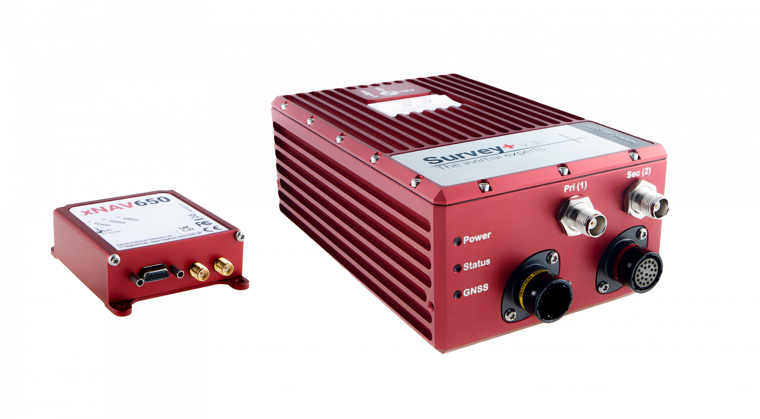
OxTS manufactures inertial navigation systems (INS) and proprietary software on which survey professionals have come to rely. Our devices, the Survey+ and the xNAV650, output highly accurate position, heading and pitch/roll measurements. An advanced navigation engine combines streams of data from onboard inertial measurement units (IMUs) and GNSS receivers. This data can then be used in a multitude of applications including lidar survey, mobile mapping and open road positioning.
Surveying, especially with a lidar sensor, can be a complicated art. There are many factors to consider even before you begin. However, system manufacturers involved in the survey industry, such as OxTS, are taking steps to simplify lidar survey.
The end goal for many lidar surveyors is to create an accurate point cloud. However, to produce the best possible results, the hardware and software involved must be working together in unison.
Hardware = lidar sensor and INS
Software = georeferencing, post-process and configuration
In this article, we have picked out a few of our favorite developments on the topic of simplifying lidar survey.
Research and Development
OxTS invests substantially in research and development to ensure that our hardware and software developments meet the ever-evolving demands of the survey industry. Many of the improvements generally center around improving accuracy, clarity of results and user experience. However, general industry demands also drive some development.
For example, the increasing use of drones in surveying has increased demand for smaller and lighter INS hardware. Whilst developing smaller and lighter hardware is therefore important it cannot be to the detriment of reliability and accuracy. The xNAV650 was born from this industry demand.
Although development of the xNAV650 was primarily driven by the needs of the survey industry (smaller/lighter hardware), other improvements OxTS has made to the software portfolio has focused on improving user experience.
xNAV650 and Survey+ inertial navigation systems. (Photo: OxTS)
Precision Time Protocol (PTP)
One of the major advances in OxTS INS technology over the past 12 months is PTP. The drive to include PTP capability on all OxTS Survey INS devices was the intention to help surveyors simplify the lidar survey set-up process.
When using compatible lidar sensors, such as those from Hesai and Ouster with an OxTS INS, surveyors no longer need to build complex wiring solutions. A simple ethernet ‘plug-and-play’ process is all that is required.
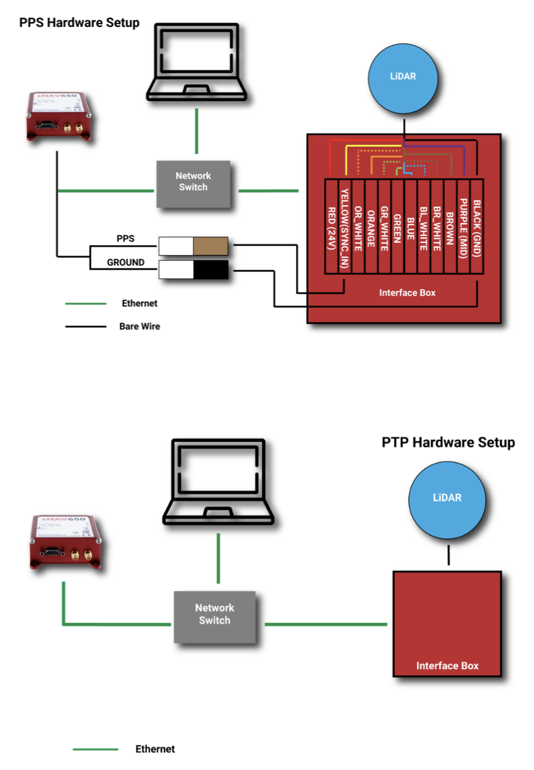
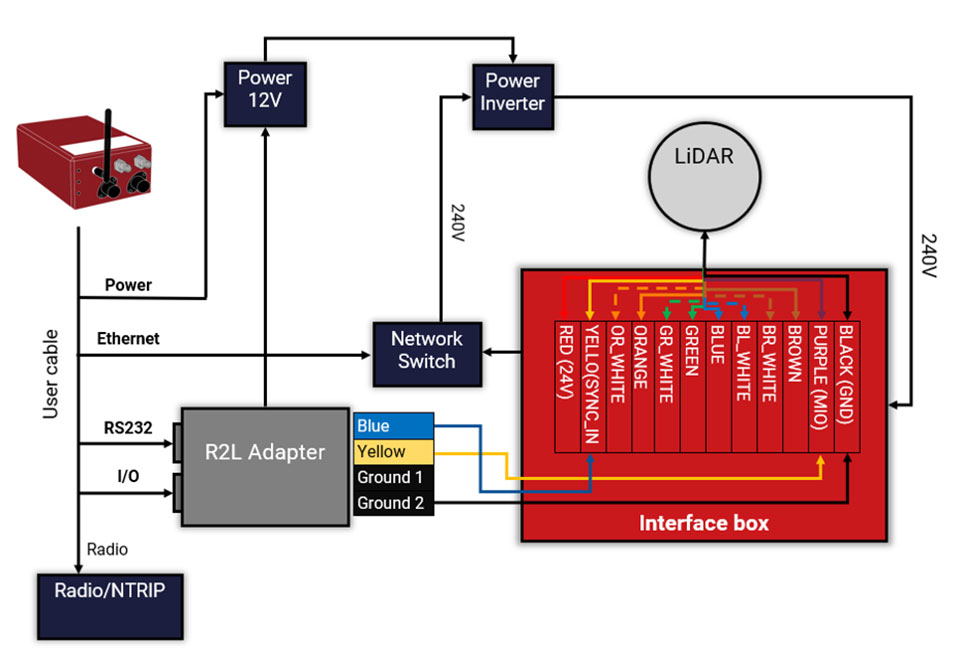
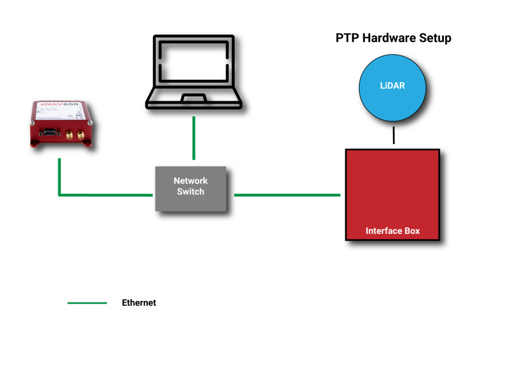
The images below show a traditional PPS wiring set-up vs PTP:
A traditional PPS wiring set-up vs PTP. (Image: OxTS)
Software
To get the desired outcome, an accurate georeferenced point cloud, from any lidar survey in a timely manner the software must be simple and straightforward to use. As the saying goes “complexity is the enemy of execution,” and this is what drives software development at OxTS.
Once the lidar and INS are plugged in and ready to survey, configuration should be straightforward. A simple configuration wizard, such as the one available in NAVsuite (OxTS’ complimentary software toolbox) should structure the set-up process so that nothing is missed.
NAVconfig – OxTS’ INS configuration software. (Image: OxTS)
The latest NAVsuite update (version 3.3) included a new PTP graphical user interface (GUI) to simplify survey set-up even further.
Other tools are included within NAVsuite that allow users to analyze, troubleshoot and post-process their INS data. Read the NAVsuite for Survey and Mapping infosheet to find out more about these.
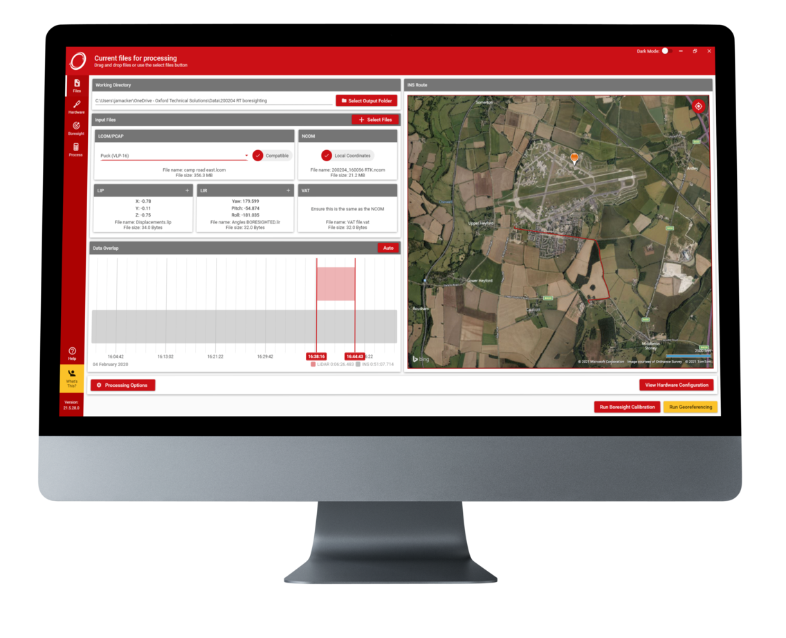
OxTS Georeferencer
OxTS Georeferencer. (Image: OxTS)
Since its launch approximately two years ago, OxTS Georeferencer has gone through some major changes. The first version included compatibility with the Velodyne VLP-16 lidar sensor. This meant that users of the VLP-16 had a quick and simple way to georeference the lidar data.
Over the course of the next 24 months, multiple new sensors have been introduced. Sensors from Hesai, Ouster, Livox and new Velodyne devices are now available, giving users more choice than ever before when it comes to choosing the hardware to do their job. Visit the OxTS Georeferencer product page for a complete list of available sensors.
Furthermore, as well as the integration of new sensors, we have introduced a raft of new features to improve the user experience for professional lidar surveyors. These include:
a 3D hardware setup viewer to enable quick and intuitive survey configuration
multiple processing options that allow users to view and process only the areas of the point cloud that are of interest therefore minimizing the data size
the ability for users to process data in a range of coordinate systems including, local coordinates, ECEF, LLA (latitude, longitude and altitude)
processing advances that enable users to process data faster than ever before.
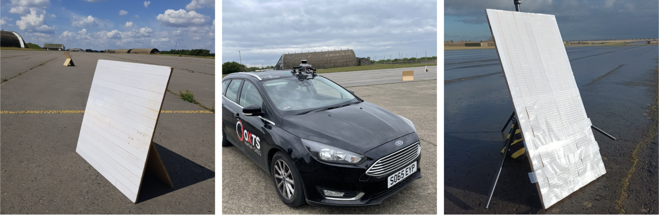
Data-Driven Boresight Calibration
One of the most challenging parts of the lidar survey set-up process is aligning the coordinate frames of the lidar and INS devices. Failure to align these with sufficient accuracy can lead to blurring and double-vision in point clouds.
Many surveyors try to do this by eye, or by developing expensive CAD models, however there is a simpler, quicker and more cost-effective way – using data.
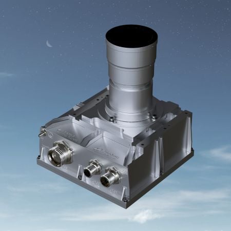
Built into OxTS’ lidar georeferencing software OxTS Georeferencer, there is an optional boresight calibration tool. It requires the surveyor to survey two static “targets” (see the images below) from multiple distances and angles. The data is then calibrated, and the angle displacement calculated to a tenth of a degree.
OxTS Georeferencer includes an optional boresight calibration tool. (Photos: OxTS)
Once the initial boresight calibration has taken place, if the setup is not altered in any way, the coordinate frame alignment will be valid for any future survey.
The Future
In the coming weeks and months, the development of new hardware and software features will further streamline the survey process.
Stringent testing on both fixed-wing plane and helicopter proves reliability and performance
Honeywell has successfully demonstrated several advanced alternative navigation technologies intended to help ensure seamless navigation, even when GPS signals are blocked, interrupted or unavailable.
Testing took place on both an Embraer E170 aircraft and an AgustaWestland AW139 helicopter.
Alternative navigation systems use sensors such as cameras, star trackers, radars and radios to augment and or aid inertial navigation systems. These systems correct inertial navigation systems in environments where GNSS are denied.
“Our customers are seeing an increase in both intentional and unintentional navigational disruptions, including jamming for GNSS-based navigation,” said Matt Picchetti, vice president and general manager, Navigation and Sensors, Honeywell Aerospace. “There hasn’t been a single set of solutions that meet all our customers’ operational needs, so we decided to create one. Our modular and scalable alternative navigation technologies are setting a new benchmark in terms of reliability and performance in GNSS-denied environments compared with what is available in aviation today.”
Alternative navigation technologies provide vital position, velocity and heading information in GNSS-denied environments. The successfully demonstrated technologies onboard the E170 and AW139 include:
Vision-Aided Navigation. Honeywell’s vision-aided navigation system achieved GPS-like performance on both the Embraer E170 and AW139 platforms during GPS-denied conditions. Additionally, the technology showed 67% improvement in GPS-denied performance compared with earlier testing in 2021. The system uses a live camera feed and compares it with maps to provide a passive, not jammable, and highly accurate absolute position.
Celestial-Aided Navigation. Honeywell’s celestial-aided navigation system on the Embraer E170 achieved an accuracy of 25 meters circular error probability of 50% (CEP50). This represented a 38% improvement in GPS-denied performance compared with tests in 2021. Most importantly, this is the first time a resident space objects-based (RSOs) navigation solution was demonstrated on an airborne platform, as most competing solutions rely only on star-based navigation. The system uses a star tracker to observe stars and RSOs to provide a passive, not jammable solution with GPS-like accuracy in GPS-denied or spoofed conditions.
Magnetic-Anomaly-Aided Navigation. Honeywell conducted real-time magnetic-anomaly-aided navigation on the Embraer E170 airborne platform. This is a historic milestone, as almost all previous magnetic tests were done in special environments to mitigate electromagnetic noise. Honeywell demonstrated this passive, not jammable, all-weather 24/7 technology on an embedded platform, which measures Earth’s magnetic strength and compares it with magnetic maps to accurately identify the position of the vehicle.
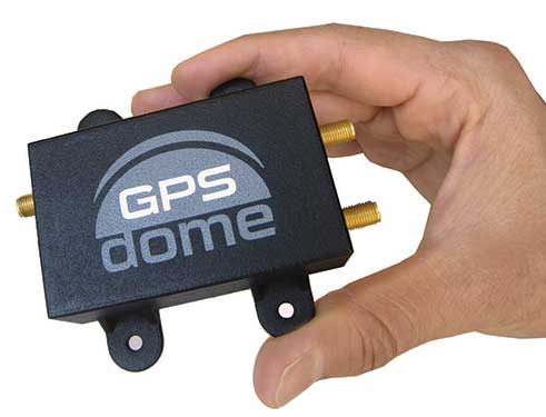
Photo: InifiDome
Additionally, Honeywell demonstrated that inertial navigation systems, when paired with the GPSDome (an anti-jamming device), showed significant improvement in position accuracy and integrity performance in the presence of GPS jamming. The ability of GPSDome to enable tracking of GPS satellites under more aggressive jamming environments reduces performance degradations that come with GNSS-denied conditions.
Alternative navigation prototype systems will be available in 2022, with initial deliveries expected to start in 2023.
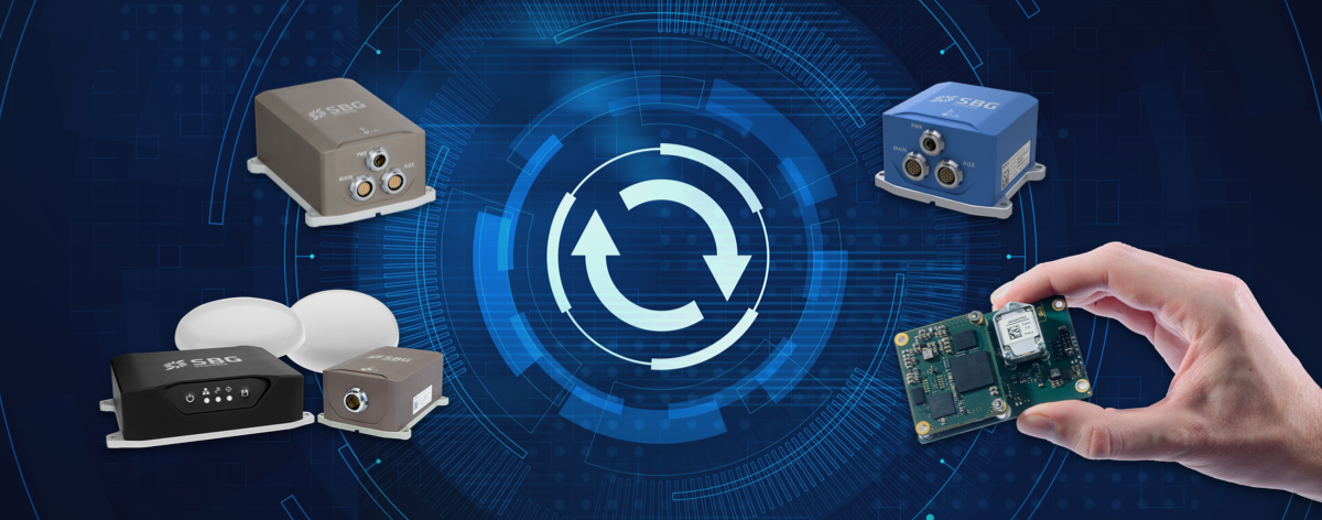
SBG Systems has released a major firmware update for all its high-performance inertial navigation systems (INS), including its Ekinox, Apogee, Navsight and Quanta brand sensors.
Developed in collaboration with customers, firmware 4.0 provides new features and is designed to make integration easier for system designers. It aims to provide improvements in these areas:
System accuracy and robustness
Enhanced heading in a single antenna allows for easier UAV survey operations.
Improved GNSS antenna auto lever arm calibration provides a faster and easier system setup.
Easier system integration
New PTP and NTP features for time synchronization eliminate the need and cost of an external timing module.
An integrated NTRIP client eases access to NRTK/VRS correction services.
A logged RTCM raw stream eases post-processing in SBG Systems’ post-processing software Qinertia using the user’s NRTK/VRS data.
A new Access Rights Management System sets up specific user roles.
Two serial outputs have been added on Navsight and Quanta for advanced survey setups.
REST API has been introduced for power users and integrators.
Inertial Labs has released a new generation of GPS-aided inertial navigation systems (INS) for applications such as UAVs, helicopters and lidar surveys.
The company also has released two new inertial measurement units (IMUs) for measuring angular rates and accelerations for motionless and dynamic applications.
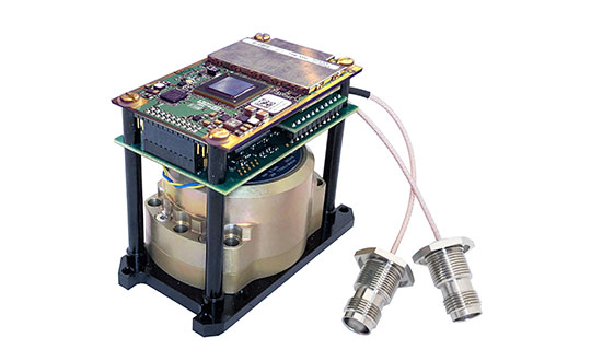
INS-DH-OEM
The INS-DH-OEM. (Photo: Inertial Labs)
The high-accuracy INS-DH-OEM is designed for easy integration into custom enclosures and higher order integrated system applications. It combines the HoneywellHG4930 inertial measurement unit (IMU) into a GPS-aided INS to provide high-accuracy orientation, position, velocity and timing for land and aerial systems.
Consisting of three axes each of high-precision accelerometers and gyroscopes, the accuracy of the HG4930 plays a key role in the exceptional performance of the INS-DH-OEM. With input from the IMU, the INS-DH-OEM has a pitch-and-roll accuracy of 0.015 degrees real-mean-squared (RMS) for dynamic applications, and a pitch-and-roll accuracy of 0.01 degrees for motionless applications.
Another key factor for the INS-DH-OEM is its use of the NovAtelOEM7720 dual-antenna GNSS receiver. The OEM7720 is an all-constellation, multi-frequency heading and positioning solution with TerraStar PPP correction services and advanced interference mitigation features.
With aiding data from the OEM7720, the INS-DH-OEM features a 2-meter baseline heading accuracy of 0.05 degrees RMS for both static and dynamic applications. As a result, the INS-DH-OEM is a high-performance solution in line-of-sight and beyond line-of-sight antenna-pointing applications.
A reliable solution in varying environments, the OEM7720 ensures that the INS-DH-OEM is outputting the most accurate GNSS-aided data by supporting GPS, GLONASS, BeiDou, Galileo, NavIC (IRNSS), and QZSS constellations.
The INS-DH-OEM can be applied in a wide range of aerial applications such as remote sensing, flight control and photogrammetry in which the INS-DH-OEM provides accurate positioning, navigation and timing (PNT) data for multi-rotor drones, fixed-wing drones and other UAVs performing these tasks. This data is paramount in the accuracy of these applications’ deliverables such as point clouds, orthomosaics and photogrammetric plots.
Weighing 280 grams and measuring 85.7 x 62.5 x 52.0 mm, the INS-DH-OEM is a lightweight, compact system that can be fitted with custom enclosures or integrated into higher order systems such as lidar payloads. It is compatible with scanners from many lidar manufacturers: Livox, Velodyne, Ouster and Quanergy. This adaptability, coupled with top-of-the-line subcomponents and Inertial Labs’ sensor-fusion expertise, make the INS-DH-OEM the suitable for UAVs, UGVs, antenna pointing, and many more applications.
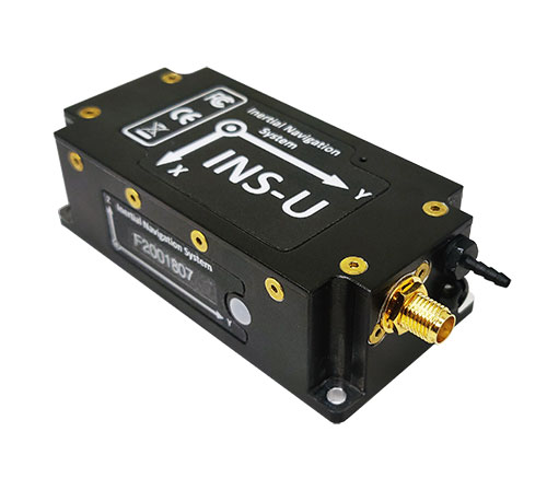
INS-U
The INS-U. (Photo: Inertial Labs)
The new INS-U GPS-aided INS with air data computer (ADC) output signal is based on a u-blox module.
The INS-U a fully integrated INS, attitude and heading reference system (AHRS), IMU and air data computer high-performance strapdown system that determines position, navigation and timing information for any device on which it is mounted.
The INS-U utilizes a single antenna, multi-constellation U-Blox GNSS receiver. With access to GPS, GLONASS, Galileo, QZSS, and BeiDou, the INS-U can be used in a variety of GPS-enabled environments and is protected against spoofing and jamming. Additionally, the INS-U is comprised of two barometers, a miniature gyro-compensated fluxgate compass, and tri-axis temperature calibrated advanced MEMS accelerometers and gyroscopes. These high-performance sensors, along with Inertial Labs’ new on-board sensor fusion filter, state of the art guidance and navigation algorithms, provide accurate position, velocity, and orientation of the device under measure.
Perhaps the most defining feature of the INS-U is its embedded ADC. An essential avionics component for modern UAV applications, an ADC outputs static & dynamic pressure, pressure altitude, calibrated & true airspeed, true angle of attack, rate of climb, and wind speed of the device under measure. This data, combined with inertial reference information, provides UAVs with accurate information about the unit and its relation to its environment.
By using data from an INS, AHRS, IMU and ADC, the INS-U provides a complete navigation solution for UAV and Helicopter applications. The unit can use time-of-flight aiding data from a ground station for long term GNSS-denied conditions as well as external position and heading so it can still output accurate PNT information regardless of the environment.
The INS-U is a lightweight and compact solution with dimensions of 82 x 40 x 26 mm and a weight of less than 200 grams. This, along with an IP67 environmental enclosure, ensures that the INS-U can meet the environmental requirements and size and weight restrictions of a wide range of applications.
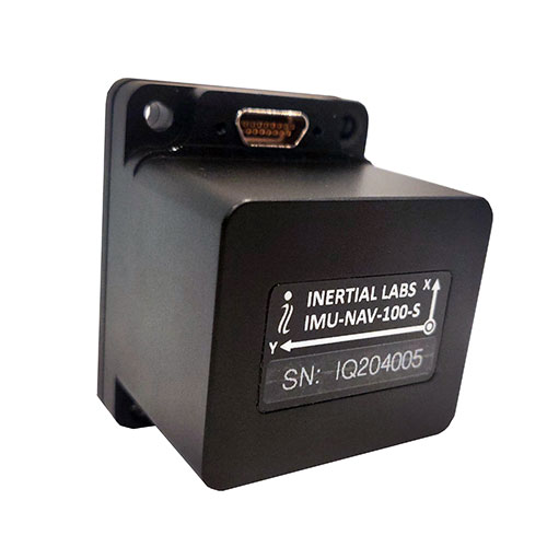
IMU-NAV-100
The IMU-NAV-100. (Photo: Inertial Labs)
The IMU-NAV-100 is a tactical grade IMU for wide range of higher order integrated system applications.
The newest addition to the Inertial Labs Advanced MEMS sensor-based family, the IMU-NAV-100, is now the best performing IMU that Inertial Labs offers. The IMU-NAV-100 is a fully integrated inertial solution that measures linear accelerations, angular rates, and pitch and roll with high accuracy utilizing three-axis high-grade MEMS accelerometers and three-axis tactical grade MEMS gyroscopes.
The IMU-NAV-100 features continuous built-in test, configurable communications protocols, electromagnetic interference protection, and flexible input power requirements which allow it to be easily integrated in a variety of higher order systems.
The IMU-NAV-100 line contains two options to accommodate a variety of projects.
The IMU-NAV-100-S is best for projects that require high performance stabilization for antenna and line-of-sight stabilization systems, motion control sensors, and platform orientation and stabilization systems. With a gyroscope angular random walk of 0.04 deg/√hr, the IMU-NAV-100-S is specialized to provide accurate data for stabilization applications.
The IMU-NAV-100-A is best used in a variety of systems such as GPS-aided INS, AHRS, and motion reference units. Regardless of the application, the IMU-NAV-100 is the company’s best performing IMU to date, providing a pitch-and-roll accuracy of 0.03 deg RMS. Fully calibrated, temperature compensated, and mathematically aligned to an orthogonal coordinate system, the IMU contains up to 0.5 deg/hr bias in-run stability gyroscopes and 0.003 mg bias in-run stability accelerometers with very low noise and high reliability.
Oxford Technical Services (OxTS) has launched precision time protocol (PTP) master functionality on all of its next-generation inertial navigation systems (INS).
PTP is a network-based time synchronization protocol used to synchronize all clocks throughout a computer network. It is used in many industries, but most notably in finance to synchronize transactions, mobile-phone tower transmissions and subsea acoustic arrays.
Time synchronization
In many commercial organizations, millisecond-level device synchronization as offered with network time protocol (NTP) is sufficient. However, in surveying and automotive testing environments where there is more than one clock source (lidar and inertial navigation systems, or INS, for example), final results can suffer from time drift if millisecond — and not microsecond — synchronization is used.
Time drift becomes relevant as soon as you introduce more than one data acquisition system working in parallel. This is because each system will have its own timing error, and over time this error will grow and create drift.
For surveyors, time drift can negatively impact point clouds by making object recognition difficult, subsequently leading to blurring and double vision.
For automotive engineers, when running campaigns, analysis of events within your data may be misaligned, making the analysis more difficult and/or less efficient.
Stamp out time drift
To stamp out time drift, it is important to use the most accurate clock source available.
A key component of an INS is the GNSS receiver. The GNSS receiver acquires data, including timing information, directly from multiple GNSS constellations (GPS, GLONASS, BeiDou and Galileo). The GNSS receiver, coupled with the inertial measurement unit within the INS, allows users to benefit from the centimeter-level position accuracy that is so important in surveying and automotive testing environments.
These satellite systems house the most accurate time source possible — atomic clocks — meaning that devices connected to a network that includes an INS can take advantage of this time source owing to the GNSS receiver within the INS.
Simpler setup for lidar use
By migrating from a traditional PPS hardware set-up, which involves connecting and wiring multiple cables, to a PTP setup, which is essentially an Ethernet “plug-and-play” solution, users can also make day-to-day use of the equipment simpler and more efficient.
Without PTP – using PPS setup. (Image: OxTS)
An example PPS hardware setup with a PTP-enabled network. (Image: OxTS)
This much-improved hardware setup allows surveyors and automotive test engineers to be up and running in a much shorter time frame than previously possible.
Adding value to the automotive industry
The addition of PTP also adds value for automotive users. With cars-under-test incorporating multiple sensors (lidars, cameras, etc.), synchronizing all that data can help support accurate analysis after the test is complete.
OxTS is continuing to develop its PTP solution by working on PTP slave functionality and improving the configuration process, which will provide greater flexibility in typical automotive setups that use data acquisition (DAQ) for larger sensor networks.
Summary
PTP as a time synchronization method is becoming more popular, particularly in the lidar industry, with manufacturers such as Ouster and Hesai enabling PTP on their sensors.
The shorter “time to survey” gives customers a much-enhanced user experience, and the higher quality final output on offer means that many users will demand their sensors are PTP-compatible before considering them for their projects.
Manufacturers of complimentary sensors, such as INS, need to build the capability into their product sets to allow them to be fit for the future.
Various OxTS INS are available to use PTP, including the new xNAV650, the company’s new small, lightweight and affordable INS for applications where payload size and weight matter. Learn more about the xNAV650 INS.
Users can also find out more about OxTS and its range of PTP-enabled devices by visiting its dedicated landing page, OxTS PTP-enabled INS devices.
Advanced Navigation, in partnership with quantum technology company Q+CTRL, will create a quantum-enhanced inertial navigation solution for space launch vehicles, satellites and landers. The design of this inertial navigation technology for long-endurance space missions will be pivotal to NASA’s space exploration initiative, the Artemis Lunar Exploration Program.
The work will be done under a Moon to Mars Supply Chain Capability Improvement grant by the Australian federal government.
The quantum-enhanced navigation system will enable NASA and its partners in the international space exploration community to execute deep space, lunar and planetary missions that were previously not possible.
Artemis is NASA’s human lunar exploration plan, with the program aiming to send the first woman and next man to the surface of the Moon by 2024. Scientists have long acknowledged the Moon as a rich source of information regarding Earth and the Solar System. Using the findings from the Moon. NASA will then prepare to launch missions to Mars.
To meet NASA’s space exploration initiatives, high-end, highly accurate inertial navigation technology is vital to the mission’s success. The groundbreaking inertial navigation systems developed by Advanced Navigation have been recognised by the international aerospace community as a superior technology to help pioneer a new age of space exploration and discovery for humanity.
For Advanced Navigation, this is just the beginning. “In the long-term view of this critical initiative, team activities following this project will establish an ongoing manufacturing opportunity and capacity that is central to the emerging Australian space industry,” said Chris Shaw, co-CEO of Advanced Navigation.
Advanced Navigation was founded in Sydney in 2012 by engineers Xavier Orr and Chris Shaw to commercialize thesis research into AI neural network-based inertial navigation. The first product met the market with great success and the company expanded rapidly adding a portfolio of navigation offerings and moving into a diverse range of deep tech fields such as underwater acoustics, GPS, radio frequency systems, sensors and robotics.
Today Advanced Navigation is a supplier to companies including Airbus, Boeing, Tesla, Google, Apple and General Motors. Advanced Navigation is headquartered in Sydney with a large research facility in Perth and sales offices around the world.
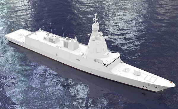
The F-110 frigate being developed for the Spanish Navy. (Artist’s concept: Spanish Ministry of Defense)
The technology multinational GMV has signed a contract with Spanish corporation Navantia to develop and supply its SENDA navigation system for the future F-110 frigates.
The F-110 frigates represent a technological leap forward in platform systems and its combat system, incorporating Industry 4.0 technologies to improve lifecycle-long system management.
The various F-110 systems call for a continuous, precise, and trustworthy positioning, speed and attitude source. With this purpose in mind, SENDA incorporates multi-constellation (GPS and Galileo) satellite navigation technology compatible with both civil and military signals, plus differential GNSS corrections. It combines its GNSS navigation data with data received from external sensors, such as inertial navigation systems (INS) and pitometer logs. It includes state-of-the-art algorithms to provide robust navigation in contested GNSS scenarios.
SENDA also includes a timing server that generates highly precise and stable timing signals, allowing the ship’s systems to synchronize with GPS time. SENDA guarantees timing-reference stability and negligible drift, even during prolonged periods of GPS downtime.
SENDA is a redundant system with two complete functional subsystems working in active-active configuration, together with redundant GNSS signal distribution. Both systems, monitored in real time, exchange information to provide the overall system with the best possible solution.
GMV has experience in aeronautics, land and naval sectors with platforms such as the Atlante tactical long-endurance UAV, the 8×8 Dragon ground vehicle and now the F-110 frigates.
GMV worked with the Spanish Ministry of Defense MoD to develop a system prototype during the F-110 definition phase. The future F-110 frigates will replace the current Santa María class frigates starting in 2026.
Oceanographic & Geophysical Instruments (OGI) has selected iXblue’s Atlans INS to provide robust and uninterrupted data georeferencing to its newly unveiled mobile-mapping lidar solution dedicated to road assessment surveys.
A fully integrated mobile mapping solution, this new vehicle-based system integrates advanced systems to provide highly detailed georeferenced survey data to transportation departments throughout the United States.
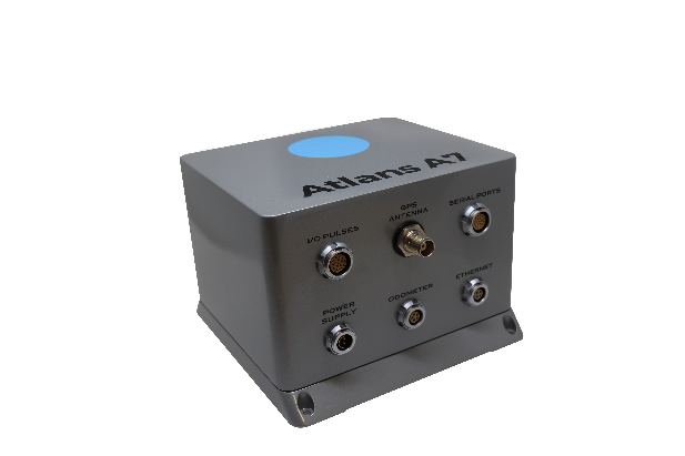
“Highly accurate and reliable georeferencing of the collected data being crucial for road assessment operations, we were seeking a compact and robust navigation solution for our mobile scanner project,” said Darren Moss, program manager at OGI. “We tested other inertial navigation systems (INS) during mobile surveys in New York City and Boston with poor results, as those INS units relied mainly on GPS signals. Maintaining good GPS signals in the urban canyons of large cities proved to be impossible. This deeply impacted the georeferencing of the acquired lidar data, leading to highly inefficient operations. This is the reason we turned to iXblue’s Atlans A7 INS.”
Based on fiber-optic gyroscope (FOG) technology, the Atlans A7 north-seeking INS offers highly accurate and robust data georeferencing. Resistant to GPS outages, it enables continuous acquisition operations within environments lacking continuous GPS signals. The Atlans A7 is a valuable system for high-accuracy data acquisition without interruption.
“Working with iXblue in other markets, we were familiar with the high-quality instrumentation they are known for. We were confident their FOG-based INS systems would perform even during GPS outages,” Darren said. “By choosing the Atlans A7, we are assured to get robust and uninterrupted georeferenced data in urban environments, tunnels, forests, and mountainous areas, which is crucial for our customer’s operations. With this INS, iXblue brings high-end FOG performance to the mobile-mapping industry at a very affordable price.”
“The Atlans A7 integrates very well within our new mobile lidar solution and, combined with Teledyne Optech Polaris high-resolution lidar scanner and QPS Qinsy display and acquisition software, it brings high-accuracy and efficiency to the core of our Mobile lidar solution,” Darren said.
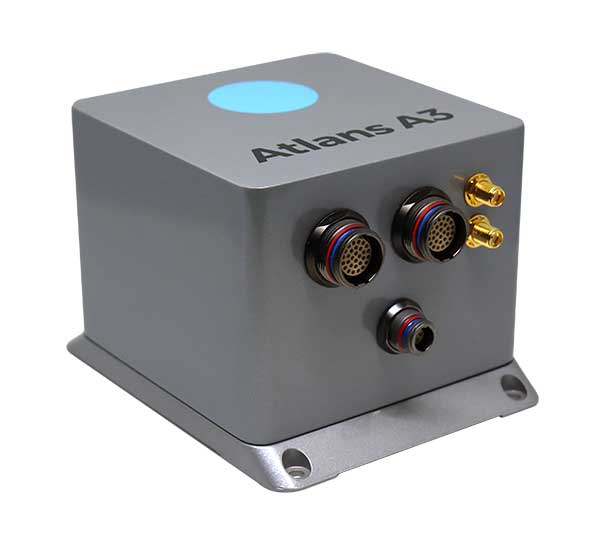
iXBlue has launched a new range of FOG-based inertial navigation system (INS) dedicated to land and air mobile mapping applications, the Atlans Series. iXBlue is high-tech company specializing in the design and manufacturing of advanced navigation and georeferencing solutions.
Based on iXBlue’s fiber-optic gyroscope (FOG) technology, the Atlans Series is a scalable range of north-seeking and north-keeping inertial navigation systems. They provide FOG performance to the full spectrum of land and air mobile-mapping applications and offer highly accurate positioning (up to 0.01 meter) in all conditions, including within GNSS-denied environments such as urban canyons, mountainous or forests areas.
“Our existing high-grade Atlans A7 INS had already been adopted as the preferred georeferencing solution by leading U.S. companies operating in the pavement condition survey industry,” explained Marine Slingue, vice president, iXBlue. “Having identified the high potential of our technology for other land and mobile mapping applications, we decided to develop a complete range of scalable INS that each meet the specific requirements of every applications. With our new Atlans Series INS, we are now bringing the unrivaled georeferencing accuracy performance offered by the FOG technology to all land and air mapping applications, enabling robust and uninterrupted data-acquisition operations.”
Quick and simple to install on all platforms, the new Atlans Series INS offers efficient “set-and-forget” operations for a wide range of land and air applications including asset inventory, pavement condition survey, vehicle automation, HD mapping, automotive testing, ground-truth, airborne surveys (UAVs, planes, helicopters), as well as precision pointing.
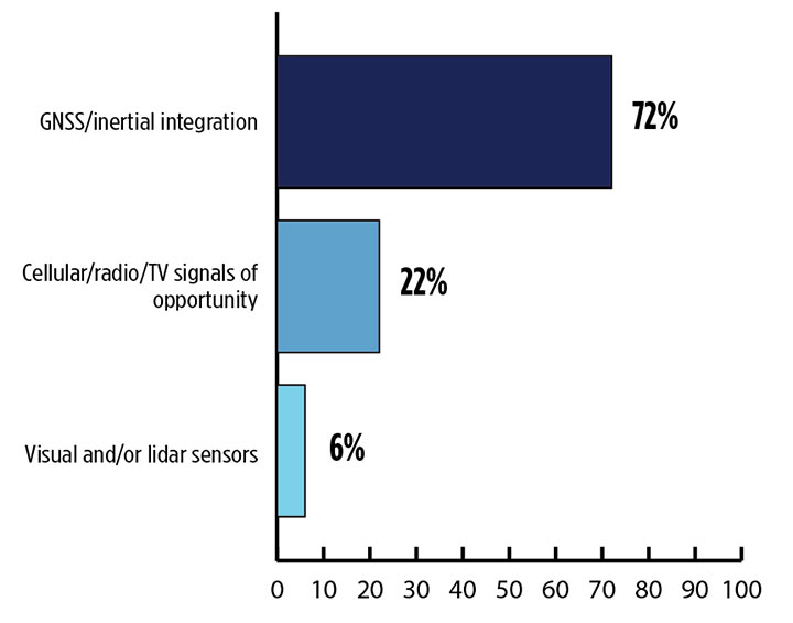
Signals other than GNSS are the key to positioning for both the transportation and machine control markets. While many solutions are being developed, inertial navigation systems (INS) are emerging as the primary GNSS co-star.
In our survey, nearly three quarters (72%) of respondents in this sector said positioning could best rely on tight integration between GNSS and INS. For comparison, inertial technology wasn’t even mentioned in the 2017 State of the GNSS Industry Report. This year for the first time, GPS World offered an Inertial Buyers Guide for our readers (see our May issue).
What is the best additional solution for positioning in GPS/GNSS-challenged environments? (Source: GPS World 2018 State of the GNSS Industry survey)
Practical autonomous navigation — the current ambition of automakers (and Google) — hits a roadblock when it comes to uninterrupted positioning. We all know GNSS reception has its limits, notably in many places that vehicles travel such as tunnels, beside tall buildings and in parking garages. Inertial positioning fills that gap, making it especially advantageous for meeting the challenges of autonomous navigation.
Inertial measurement units are generally based on multi-axis combinations of precision gyroscopes, accelerometers and magnetometers using algorithms to determine location, direction and position. Gyroscopes measure the angular velocity; accelerometers measure overall acceleration; and magnetometers provide the direction of the magnetic field.
Micro-electro-mechanical (MEMS) techniques have reduced the size, power consumption and costs of INS systems considerably, enabling their use in ever more applications, including unmanned aerial vehicles.
As a result, products that combine GNSS + INS are being introduced at an increasing rate, with more than a dozen major announcements in the past year. According to one study, the INS market is projected to grow from US$11.89 billion in 2017 to US$19.67 billion by 2023, a compound annual growth rate of 8.76%.
For more results from the 2018 State of the GNSS Industry, see this page.