Today, Hemisphere GPS introduces the Vector VS330 and Vector VS131 GPS compass products that provide high performance heading, position, heave, and attitude data. The new Vector products are designed for professional marine applications such as hydrographic and bathymetric surveys, dredging, oil platform positioning, and buoys that demand a high level of 3D positioning accuracies.
Based on Hemisphere GPS’ Eclipse GNSS technology, Vector VS330 uses the most accurate differential corrections including RTK, L-band, SBAS, and beacon. The smart intelligence from our MFA firmware provides differential solutions by automatically switching to the next best differential source if the original source is no longer available, Hemisphere GPS said.
Vector VS330 is Hemisphere GPS’ flagship receiver and computes heading information with better than 0.01 degrees accuracy when using a 10-meter antenna separation. Positioning accuracy is better than one centimeter in RTK mode or four centimeters when using OmniSTAR HP corrections. Vector VS330 also provides five-centimeter RTK heave and 0.01 degree pitch and roll accuracies.
Combining Hemisphere GPS’ Crescent Vector and LX-2 receivers with two separate antennas, the Vector VS131 computes heading information with better than 0.03 degrees accuracy when using a five-meter antenna separation and better than 50 centimeter position accuracy when using L-band, SBAS, or beacon corrections. Vector VS131 accepts most differential correction signals for unparalleled flexibility to obtain sub-meter positioning in all regions.
The ruggedness of the new Vector enclosure also makes it suitable for more harsh environment installations like machine-control applications, including agriculture, heavy construction equipment, mining equipment, unmanned vehicles, cranes, and other machinery or industries that require very accurate heading and positioning solutions. The Vector’s versatility for providing heading, position, heave, and motion makes it directly compatible with the most popular hydrographic and side scan survey packages. Vector VS330 and VS131 include an intuitive and easy-to-follow user interface to facilitate fast installations.
“Vector VS330 and Vector VS131 are premium additions to Hemisphere GPS’ Vector series product line,” said Phil Gabriel, vice president and general manager, Precision Products, for Hemisphere GPS. “As the demand for more rugged and precise GPS equipment increases, we are meeting this demand by exceeding the accuracy of competitors’ products while being significantly more affordable.”
Vector VS330 and Vector VS131 will be featured by Hemisphere GPS in hall 9, stand B.62 at the INTERGEO Conference and Trade Fair in Hanover, Germany, from October 9-11. Both products will be available for shipping in November through the Hemisphere GPS Precision Products global dealer network.
Topcon Positioning Systems announces the MG-A8 antenna for navigation and precise positioning in marine applications. According to Topcon, the new MG-A8 marine antenna provides exemplary GNSS signal tracking while not being susceptible to signal jamming from other sources, such as Inmarsat communications.
The MG-A8 antenna can be used in DGPS mode for meter-level navigation purposes but can also be used for RTK centimeter level positioning in areas where there is a network of reference stations available to support this level of precision. With its RTK capabilities, the MG-A8 is a “preferred solution for applications such as dredging in inland river channels and waterways,” said Tom Morris, TPS senior product development manager.
“This antenna is designed with challenging marine applications in mind. It is accurate, rugged, reliable and affordable.”
Trimble has announced that its latest generation of GNSS receivers for marine construction and hydrographic survey now support Fugro's Marinestar positioning services. Using satellite-delivered Marinestar corrections with Trimble SPS855 and SPS555H GNSS receivers, contractors can conduct dredging work up to 20 miles offshore, without relying on land-based infrastructure such as reference stations and radio networks. The Fugro Marinestar positioning service expands the operating environment for contractors using the Trimble marine construction GNSS receivers and enables decimeter accuracy for precise placement of dredging equipment and dredged materials.
The Trimble SPS855 GNSS Modular Receiver provides accurate water level information and tidal height for a construction or dredging location, which is significantly more cost-effective than with conventional methods. Its modular design means the contractor can place the receiver inside the vessel cabin for maximum security and protection from the environment while mounting the GNSS antenna outside for optimized signal strength. The Trimble SPS555H Heading Add-on Receiver provides exact heading information for projects that require precise orientation of a dredging vessel.
The Marinestar positioning service from Fugro offers two options: Marinestar GPS — a high-performance, high-accuracy GPS augmentation service; and Marinestar GNSS — a high-performance augmentation service for both the GPS and GLONASS.
The new Trimble SPS855 GNSS Modular Receiver and SPS555H Heading Add-on Receiver are available now through the Trimble Marine Construction distribution network. Subscription to the Marinestar GPS and Marinestar GNSS service is available for dredging and other marine construction applications through Fugro.
Large coordinated cyber attacks from North Korea near its border with South Korea produced electronic jamming signals that affected GPS navigation for passenger aircraft, ships, and in-car navigation for roughly a week in late April and early May. To date, no accidents, casualties, or fatalities have been attributed to jammed navigation signals aboard 337 commercial flights in and out of South Korean international airports, on 122 ships, including a passenger liner carrying 287 people and a petroleum tanker. One South Korean driver tweeted “It also affects the car navigation GPS units. I am getting a lot of errors while driving in Seoul.”
South Korea experienced similar electronic attacks in March 2011, and in August and December of 2010, all of which were blamed on the North. The South Korean Defense Ministry said it is developing anti-jam programs to counter the attacks, which are being launched by what it termed a regiment-sized electronic warfare unit near the North Korean capital Pyongyang, and battalion-sized units closer to the inter-Korean border.
“Despite disruption in GPS, there is no serious threat to the safety of flights because planes are using other navigation devices,” claimed a Transport Ministry spokesperson. Officials say planes can use other navigation devices like very-high-frequency omni-directional range (VOR) and inertial navigation systems.
“We have traced the jamming signals to the direction of Kaesong,” said a Korean Communications Commission deputy director. Kaesong lies roughly 10 kilometers from the border between the two countries, and roughly 50 kilometers from downtown Seoul, Incheon International Airport, and the Yellow Sea.
It is unknown how long the jamming may continue, or when it might resume if halted. In March 2011, GPS jamming signals from the North lasted for 10 days during an annual U.S.-South Korea joint military drill. The motivation for North Korea to develop and employ anti-GPS technology would appear to come from its fear of attack by GPS-guided cruise missiles that might target key sites within the country. Clearly, any such military capability would require regular testing.
China is well known as a source of mass-produced small GPS jammers widely available over the Internet, but equipment on this scale would not be capable of jamming at the distances stated above. “At least one, or possibly more Russian companies are selling fairly powerful GPS jamming equipment,” said one knowledgeable source.
The source also alluded to Iran’s reported use of GPS spoofing to mislead and capture a U.S. surveillance unmanned aerial vehicle (UAV). Such an effort would similarly require large and sophisticated equipment, for which the most likely source is Russia.
“Receivers which cannot tolerate LightSquared will get in trouble in North Korea!” commented one well-known GPS manufacturer. “Today’s receivers don’t have protection. We just completed our ad [for the June issue of GPS World] which somewhat covers this.”
Other sources pointed to much wider potential threats than those in the Korean peninsula or areas of strategic conflict such as Afghanistan-Iran. Local jamming attacks can be anticipated almost anywhere, anytime: harassment by insurgent groups against established governments or armed forces, or GPS-denial actions by pirates in high-density commercial shipping lanes.
Since aviation is increasingly and in some cases exclusively dependent on GPS and regional GNSS augmentations or equivalents, jamming represents a growing concern for the aviation industry, including commercial airlines. In March of this year, the U.S. Federal Aviation Administration published an updated report on “Concept of Operations for NextGen alternative positioning, navigation and timing (APNT).” It advocates GPS backup by transponder-based distance-measuring equipment (DME), supported by onboard inertial reference systems, and assisted in places by low-powered GPS-like pseudolites and wide-area multilateration. The report concludes that any GPS/GNSS backup must be multi-modal, unjammable, provide GPS-like timing, have signals extending from the ground up to all altitudes, be unaffected by line-of-sight restrictions and, preferably, have reasonably long range to keep down the number of transmitting stations required.
Commenters have pointed out that eLoran meets those requirements, except for a vertical component, limiting it non-precision approaches. The system currently does not operate in the United States, although it is undergoing limited testing. The United Kingdom has a more active program. See upcoming GPS World webinar, Alternative PNT – Backing Up Critical Infrastructure with eLoran, on May 17.
Many maritime users today believe that GPS will always be available. This is simply not the case.
By Alan Grant, Paul Williams, George Shaw, Michelle De Voy, and Nick Ward, The General Lighthouse Authorities of the United Kingdom and Ireland
GNSS availability can be affected in many ways, through events or conditions that affect constellation health, the signal-in-space, or the reception of that signal. The primary means of positioning, navigation, and timing (PNT) employed in maritime applications, whether stand-alone or augmented, has well known vulnerabilities.
This article considers three specific threats and reports on how they may affect maritime safety: GNSS interference and jamming; constellation availability; and space weather events.
Interference and Jamming
There has been a marked increase in both the use and the availability of GPS jamming equipment in recent years. The implications are that jamming units may find their way onto ferries and around ports or harbors where they will interfere with the many systems utilizing GPS, thus affecting maritime safety.
GPS jamming units are widely available on the Internet, with current models already capable of jamming L1, L2, and L5 signals. While we report here on the jamming of GPS, all GNSS constellations would be affected in a similar manner.
To understand the effects of jamming and GPS service denial on maritime safety, the General Lighthouse Authorities of the United Kingdom and Ireland (GLAs) conducted two jamming trials, in collaboration with the UK Government’s Ministry of Defence (MOD), who provided and operated the GPS jamming units. For the safety of all GPS users, and in line with MOD regulations for the peacetime use of GPS jamming units, notice was given to all national bodies. In addition, the GLAs issued notices to mariners explaining that aids to navigation (AtoNs) using GPS in the vicinity of the trials location would be unreliable during the jamming periods.
Flamborough Head. The first jamming trial was conducted off the East coast of the United Kingdom near Flamborough Head. The aim of this trial was to understand the effect GPS jamming may have on ship-borne and shore-based equipment, GLA AtoNs, and also on the crew.
The Northern Lighthouse Board vessel Pole Star steamed between two known waypoints, through an area affected by the jamming signal. Data was recorded from two typical marine-grade GPS receivers installed on the vessel, along with an eLoran receiver that provided the true position throughout the trial.
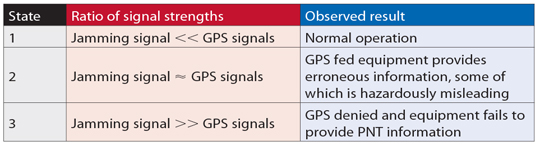
The results identified three distinct states (Table 1) corresponding to the manner in which GPS-fed equipment responded to jamming conditions. When the jamming signal was sufficiently strong to prevent reception of GPS signals, a large number of alarms sounded on the bridge almost simultaneously, providing a potentially disconcerting and confusing environment for the mariner. However, the effect that represented the highest risk was the provision of erroneous data from some GPS receivers.
Table 1. Effects observed for the three states identified from Flamborough Head trials.
Figure 1 compares an erroneous position reported by a typical marine-grade GPS receiver with the vessel’s true location. In this figure, the light blue line shows the path taken between the two waypoints.
The colors of the plotted position points indicate vessel speed. The three states described in Table 1 can be seen.
State 1 is observed at either end of the passage where the solid blue line occurs; this is where the jamming signal strength is much lower than the GPS signal strength, and the GPS-fed systems are operating normally.
As the vessel approached the main lobe of the jamming signal, indicated by the red lines, it reached an area where the jamming signal was comparable with the received GPS signals, leading to State 2. During this state, erroneous data can be observed with the receiver reporting the vessel on land traveling at high speed.
As the vessel entered the main lobe of the jamming signal, State 3 was observed: the GPS signals were swamped by the jamming signal, and the receivers failed to provide an output. Then, as the vessel continued the passage out of the jamming area, one can observe the change in states as the ratios of jamming to GPS satellite signals decrease, and GPS is reacquired.
In the worst case, the GPS receiver reported a position some 22 kilometers away from the true location. The GPS receiver nevertheless declared the position valid. This position was made worse by the fact it was reported inland at a speed of more than 100 knots, while the trial vessel steamed steadily at 10 knots. Depending on how the resulting GPS positioning data is used, it could feasibly result in vessels changing course, through the use of an autopilot, and it could also affect the vessel’s reported position to the outside world. This would then not only affect the vessel’s situational awareness but also the situational awareness of vessels in the vicinity.
The errors observed in Figure 1 were also seen on the vessel equipment fed by the onboard GPS receivers. Erroneous positions were observed on the vessel’s electronic chart display and information system (ECDIS), on the automatic identification system (AIS) positions (where loss of position prevents the unit from calculating a range or bearing to nearby vessels, greatly affecting the crew’s situational awareness), and on the vessel’s radar (Figure 2).
The results observed during these trials gave an important example of what can happen to onboard equipment as well as the impact it can have on the mariner during periods of GPS jamming and service denial. It is clear that GPS denial caused by jamming can not only prevent PNT information from being calculated, it can also result in erroneous data being presented to the mariner.
Newcastle. A second series of demonstrations was conducted off Newcastle-upon-Tyne, on the North East coast of England, to communicate the importance of resilient PNT to a selected audience. The audience included a number of key decision-makers from European and UK governments, maritime industry, mariners, and other aids-to-navigation service providers. The demonstrations took place onboard the Trinity House vessel Galatea.
For this trial, the GPS jamming unit was installed onboard the Galatea and configured to jam GPS within a small
area around the vessel. As before, two typical marine-grade GPS receivers were installed along with an eLoran receiver; for this trial, a modified electronic chart display was also installed and altered to enable two position inputs to be displayed at the same time, to compare the reported GPS and eLoran positions in real-time.
Throughout the demonstrations differential Loran (dLoran) corrections were provided using a transportable reference station installed on the shore at South Shields, to mitigate the impact of temporal variations on the eLoran position. Differential-Loran corrections were generated by the reference station and sent to the GLAs’ eLoran transmitter in Cumbria for inclusion in the eLoran Loran Data Channel (LDC) broadcast. The eLoran receiver on the vessel received the broadcast and was able to extract and apply the corrections in order to obtain an eLoran position within 9 meters (95 percent).
One demonstration scenario showed the sudden effect of a strong jamming signal, designed to simulate a jamming unit being brought onto a ferry or other vessel. This took the vessel’s equipment directly to State 3: complete loss of GPS information with a large number of alarms sounding on the bridge. The loss of GPS data prevented the Galatea’s AIS and VHF units, among other systems, from operating correctly.
Before the second scenario was conducted, the jamming unit was stopped, and all of the GPS receivers integrated into the bridge equipment were allowed to reacquire satellites and fully recover. The second scenario was designed to reflect a vessel steaming towards a jamming source. The field strength of the jamming signal was slowly increased until State 2 was observed, with erroneous and often hazardously misleading information reported.
As with the Flamborough trials, erroneous GPS positions reporting unfeasibly high speeds were observed as shown in the OPENING Figure. However, significantly more subtle errors were seen: errors where the vessel’s reported position differed only very slightly from the true location and wandered around slowly. These subtle changes produce believable positions but hazardously misleading information (HMI). While the overall result of GPS jamming on Galatea was consistent with that observed on Pole Star, there were a few marked exceptions.
The effect of GPS jamming can be seen (Figure 3) on the erroneous positions reported by the trial vessel NLB Pole Star (center right) and also on the vessel DutchProgress (top left).
The ECDIS onboard the Pole Star reported erroneous positions and ultimately failed with the complete denial of GPS. However the ECDIS on the Galatea continued to track the vessel’s position due to an additional position feed from the vessel’s gyro, making it more resilient to jamming, but only in the short term until the gyro requires re-calibration. This is carried out with its built-in GPS receiver! In addition, the AIS transceiver on the Pole Star reported the vessel’s position erroneously due to jamming, and this was observed at shore-based traffic monitoring stations.
During the demonstrations on the Galatea, the AIS transceiver did not provide any erroneous position information, as can be seen in Figure 4. These differences show that the impact of GPS jamming will be different for each vessel and depends on the model, installation, and configuration of the onboard systems.
Effect of Jamming on Safe Navigation
To navigate safely, the mariner needs reliable, clear and trusted information about where the ship is and what is going on around it, so that any threat can be located and identified. While consideration is often given to threats such as areas of shallow water, obstacles, or other vessels; consideration is not generally given to the loss of positional information, timing, or situational awareness.
Loss of GPS-derived PNT information at sea results in the loss of the vessel’s ECDIS, AIS, GPS, and DGPS receivers, preventing the mariner from being able to position the ship and others around it through what are nowadays regarded as the normal means. In addition, the systems one would normally expect to be independent from GPS, and as such available for use in GPS-denied conditions, are also affected; namely the vessel’s radar and gyro-compass.
The radar takes a GPS input to provide a “North-up” setting and the gyro-compass uses GPS to stabilize drift error. Under GPS-denial conditions these units also enter an alarm state and should not therefore be used in that condition.
Clearly GPS jamming can significantly affect the safety of mariners. From these trials it can be seen that the extent of the impact varies from vessel to vessel depending on the equipment installed and the configuration selected.
Satellite Constellation. From the users’ perspective, GNSS availability is the percentage of time they can receive usable data from sufficient satellites in order to calculate their position. The reduction in the number of available satellites in the constellation will have a direct impact on the system’s availability.
A report from the U.S. Government Accountability Office (GAO) in 2009 predicted “significant challenges in sustaining and upgrading widely used [GPS] capabilities” due to delays in launching modernized GPS satellites. The GAO reported the probability of maintaining a constellation of at least 24 usable GPS satellites could reduce to 80 percent or less by 2011, and not return to 95 percent probability consistently until 2015. This could lead to reduced satellite numbers causing coverage “windows” where less than four satellites could be observed and as such reduced GPS availability.
A later report by the GAO indicates that the probability of maintaining a constellation of at least 24 operational GPS satellites is now expected to be 95 percent for the foreseeable future. This figure is based on the current launch schedule, and although the U.S. Air Force Space Command (AFSPC) has provided reassurances, the satellite launch program has in recent years experienced delays, and therefore the risk of reduced satellite availability still remains.
Following the 2009 report, the GLAs commissioned a study to investigate the impact a reduced GPS constellation would have on users in their waters. This study was conducted by the GNSS Research and Applications Centre of Excellence (GRACE) and was split into two parts. The first part was to analyze the impact theoretically and found that with a 21-satellite constellation, GPS coverage “windows” (for example, fewer than four satellites) could last for several minutes and cover a large proportion of the UK and Ireland (Figure 5). This can cause reduced GPS availability and therefore increased likelihood of position errors affecting maritime safety.
The second part of the study investigated the effects further through a dynamic simulation, investigating the effects should a vessel be position
ed off the coast of Belfast during one of the coverage windows. For this a marine-grade GPS receiver and a simulator were used to observe the effects. The study found that the number of available satellites fell below four for several minutes and the reported position data from the receiver appeared to freeze for up to 10 minutes.
If a mariner was traveling at a speed of 35 knots when the position input froze, his reported position would be in error by 10 kilometers from an outage lasting 10 minutes. These outages are significant, and mariners need to be informed of such risks to GPS (and GNSS in the future) before they occur, so they are prepared for any disruptions.
Space Weather. Space-weather events are a particular concern to GNSS availability due to their random nature. It is known that GNSS signals are delayed proportionally to the number of free ions as they propagate through the Earth’s atmosphere enroute to the receiver. The amount of ions in the ionosphere, the total electron count (TEC), is dependant on time of day, latitude, and solar activity, among other factors. During high solar activity, the number of ions in the atmosphere is much higher than at any other time. The greater the signal delay, the larger the errors are in the satellite’s pseudo range and hence the position error can be significant.
Variation in electron density along the GNSS signal path causes signal refraction that produces phase scintillation, introducing group delay that may cause large errors in the pseudorange measurement. Diffraction of the signal wave front induces amplitude scintillation — variations in signal amplitude — with strong fades possible, leading to a GNSS receiver losing signal tracking, and at worst the GNSS navigation solution may be lost.
Solar activity is cyclical, peaking at a maximum approximately every 11 years, during which periods GNSS performance can be severely degraded, especially at equatorial, auroral and polar latitudes. The next solar maximum is predicted to occur during 2013.
During quiescent periods of solar activity, ionospheric effects on GNSS can be managed such that the residual errors caused by the ionosphere do not generally pose a problem to maritime navigation performance.
The GLAs’ DGPS corrections significantly reduce common mode errors, including the effects of the ionosphere. However, at the peak of the solar cycle with high levels of sunspot activity, solar storms and flares, the application of ionospheric models and differential corrections may be less effective, and this could increase position errors and introduce an integrity risk to maritime navigation.
Maritime navigation systems and services that rely on GNSS are at greatest risk of disruption from the ionosphere during the period from 2011 to 2015. Even during a quiet solar maximum, the occurrence of individual sun spots could produce significant effects for discrete events. The effects vary with latitude, season, and time of day (the hours soon after sunset being most affected).
Space weather events have the potential to affect GNSS availability, either by affecting the performance of the satellites themselves or by preventing signal reception.
Mitigation. In general, a number of steps can be taken to help reduce the impact of these threats:
Increase awareness of GNSS vulnerabilities.
Detect incidents and warn the mariner when they occur.
Prevent incidents from occurring, where possible, through legislation and enforcement.
Reduce as much as possible the effects of incidents when they occur, through the hardening of GNSS technology.
Have alternative means of PNT, independent of GNSS.
Understanding that these threats exist and knowing what disruption they may cause is the first step to mitigating their effects, but this does not stop them happening. Being able to identify that an event is occurring and that the data being received from the receiver may not be true is an important part of mitigating the effects.
For jamming issues specifically, the use of GPS jamming units is illegal in the UK and Ireland; however, preventing them from being used is very difficult to achieve. Jamming units are small and easily hidden; however, port-side security and vessel security procedures should prevent jamming units from being used in these locations.
It is a different case, however, to prevent a jamming unit from being used at a coastal location or headland due to the remote nature of these areas.
Mitigating the effect of jamming can be achieved in a number of ways: by limiting the effect within the receiver by using anti-jamming techniques, or by hardening GNSS receivers. Ultimately the best mitigating activity is to not rely on GNSS PNT once the integrity of the data has been compromised.
For space weather events or cases of reduced satellite numbers, there is very little action the mariner can take to remedy the problem or stop it happening. The mitigating action here is one of awareness — information forewarning the mariner that such a condition is imminent, for example.
Monitoring and detection networks can assist in providing such notifications and real-time information on GNSS problems. The need for such a network across the UK and Ireland is the subject of a different GLA publication, but the GLAs support the discussion on a body to monitor GNSS performance and to take the lead in the dissemination of key information.
For periods where GNSS availability has been affected by mutual interference, jamming, space weather events or constellation issues, the best mitigating action is to use PNT information from a second source, one with dissimilar failure modes.
Mariners need to be prepared for GNSS failures and have access to PNT information through dissimilar systems. In addition, procedures covering what to do in the case of GNSS unavailability should also be provided and rehearsed. It is with this view that the GLAs firmly promote the use of all available means of navigation.
Conclusions
All three threats to GNSS availability reviewed here could affect maritime safety. The two trials observed presentation to the mariner of erroneous data, some of which could be considered hazardously misleading, along with the degradation of crews’ situational awareness. The main effects observed were:
The presentation of random errors leading to hazardously misleading information that could, depending on installation, cause a vessel to move off course.
The presentation of erroneous and potentially misleading data to other vessels and shore-based infrastructure.
The sheer number of alarms on the bridge of the vessel could be disconcerting and distracting for the mariner.
The loss of GPS-fed systems, which can create an unfamiliar bridge situation and remove safety-critical systems from operation.
A large number of bridge systems are integrated with GPS and enter an alarm state during periods of GPS outage.
The loss of GPS or a lack of integrity in the reported information leads to an unfamiliar situation on the bridge.
The crews of the Pole Star and the Galatea were expecting to lose GPS, were well-trained, and had primed other systems so they could navigate safely. In real life, there would be no advance notice, and the impact on the crew would be more severe.
The impact of low satellite numbers, as predicted in the 2008 GAO report, could produce poor constellation availability and a loss of PNT information for a considerable period of time. This could result in the same outcome as observed in the GPS jamming trials when entering State 3, where many systems on the bridge failed and entered an alarm condition.
Space weather events are difficult to predict both in terms of when they may occur and their severity. Events could affe
ct satellite positions, their operation, and the reception of their signals by the user, and are clearly a threat.
The GLAs strongly support the need for a resilient PNT solution, one that could continue to provide reliable information during such threats for the safety and benefit of all mariners.
Acknowledgment
This article is based on a paper given at the Institute of Navigation’s 2011 International Technical Meeting.
Alan Grant is a principal engineer for the Research and Radionavigation Directorate of the GLAs of the UK and Ireland, technical lead and project manager for all GNSS projects there. He has a Ph.D. from the University of Wales.
Paul Williams is a principal development engineer with the Directorate and currently technical lead of the GLAs’ eLoran Work Programme. He has a Ph.D. in electronic engineering from the University of Wales.
George Shaw is an engineer at the Directorate and holds a master’s degree in mathematics from the University of Cambridge.
Michelle De Voy is a development engineer for the Directorate, with an MSc in oceanography from the University of Southampton and an MSc in satellite positioning from the University of Nottingham.
Nick Ward is research director of the General Lighthouse Authorities of the UK and Ireland, with responsibility for strategy and planning of research and development.
A range of unrelated events in September show that GPS, the world’s preeminent GNSS, remains a work in progress.
The first in a series of deviations from normal GPS signal broadcasts during September was noted by researches at the University of New Brunswick, among others around the globe, who found that normal signals from the L1 and L2 transmitters on the GPS satellite PRN01/SVN49 were unavailable for more than two hours on the morning of September 4.
The satellite did not transmit useful signals on L1 and L2 from about 12:00 to 14:11 UTC, as reported by International GNSS Service stations in Europe. The L5 test signal continued to be tracked by some receivers but not others.
One possible explanation for the inability to track PRN01 is that the satellite rejected an upload and automatically went into non-standard mode, resulting in GPS receivers being unable to track the L1 and L2 signals. In other words, the L1/L2 transmitters were still on but transmitting a non-standard signal.
“It is not known for sure what actually happened with the satellite, but perhaps it is related to the ongoing issues with the signal reflections on the satellite and that the GPS Wing was conducting further tests,” said Richard Langley, GPS World’s Innovation editor and professor at the University of New Brunswick. “Luckily, the problem was short lived.” As to why some receivers continued to track the L5 signal but others did not, Langley speculates that some receivers may need to acquire and track the L1 signal before they can track the L5 test signal.
HDOP Warning. On September 10, the U.S. Coast Guard Navigation Center (USCG NavCen) issued a high dilution of precision (DOP) warning for certain locations in the U.S., Asia, and Oceania, reporting that GPS users might experience a temporary degradation in GPS reception in parts of the southwest and central United States from 13:02 UTC to 13:23 UTC on September 11.
“The warning is based on a best-four satellite scenario: what the DOPs would be if we only used the best four satellites (the combination providing the lowest DOP value) of all the satellites in view at a particular location,” said Langley.
“However, most civil receivers these days track eight or 10 or all satellites in view. I contacted the Coast Guard about this, and they did another analysis and confirmed DOP spikes for all-in-view users too. Prompted by that, I did my own analyses and found that with PRN31 out of action for the delta-V and PRN01 not yet declared healthy, only five satellites above 5 degrees elevation angle (and almost colinear in the sky) will be visible at the stated locations and times, resulting in GDOP spikes approaching 100!
“So, in this case, the warning is for all users in the affected areas, not just receivers with only four channels.”
Although a window stretching from 00:30 to 15:00 UTC had been allocated for the PRN31 delta-V maneuver, prompting the high DOP alert, the GPS Wing avoided any problem to users by delaying the start of the operation until 01:27 UTC and completing it in little more than one hour. The satellite was back on line by 02:37 UTC.
Sat Moves. After 22:00 UTC September 12, system operators began transitioning satellite SVN25 (PRN25) into the broadcast almanac for all satellites. Meanwhile, they moved satellite SVN24 (PRN24) out of the almanac.
The current GPS operation control system (OCS), known as AEP, cannot handle 32 satellites. However, the recent move gave rise to speculation that the maximum number of operable satellites has now been reduced from 31 to 30, for some reason. Apparently, the military cannot allow more than 30 space vehicles to be in active service at any one time. So when a new SV is activated, one must be deactivated. SVN24 will be placed in caretaker status, ready to be brought back on line should the situation change or the 30 SV limit be overcome.
Recent pronouncements by GPS Wing personnel on the benefits of the next operating system, OCX, have stated that it will be able to handle many more satellites, as many as 60. This figure now appears in doubt.
Russian Vision. Grigory Stupak and Mark Shmulevich reported Russia’s plans to restore a full GLONASS constellation of 30 space vehicles, laying out a road map leading to full interoperability with GPS. They envisaged a world orbited by 117 navigation satellites, with GLONASS operating alongside GPS, Galileo, and China’s COMPASS, supported by a further 29 augmentation satellites. That would certainly mitigate many of the vulnerabilities of GNSS due to propagation effects — but not those from interference in the frequency bands they will all share.
Solutions Sought to GNSS Vulnerabilities
Baska conference report by David Last
The second conference on GNSS Vulnerabilities and Solutions, September 2–5 in Baska, Croatia, focused on GNSS vulnerability to space weather, unintentional interference, jamming, and multipath propagation.
The conference was a joint venture by the Royal Institute of Navigation, London, and Nottingham University’s Institute of Engineering Surveying and Space Geodesy. Sixty-four delegates, mostly European, came from 21 countries.
Nearly half the papers focused on space weather and ionospheric and tropospheric propagation, taking in long-term and short-term solar effects, scintillation, signal attenuation, tropospheric delay variations, meteorological influences, and even gravity waves. The approach of the physicists was: Understand these things and maybe you can mitigate your vulnerability to them.
GNSS vulnerability can threaten safety-critical and mission-critical systems, including navigation in the air, maritime automatic identification systems, and the transportation of nuclear waste and other dangerous materials on land. Mitigations include EGNOS (the European WAAS) and GBAS (ground-based augmentation systems.)
Road Tolling. An unexpectedly hot topic was the enthusiasm of European governments to deploy road-user charging schemes based largely on GNSS technology. Some say road pricing is a rare and novel case of GNSS users who are hostile to the technology and seeking to exploit its vulnerability to the maximum. To enforce charges through the legal system may require levels of integrity approaching those of aircraft instrument-approach systems.
Suggestions for jamming defenses came mostly from Germany: Ulrich Engel and Angelika Hirrle proposed exciting new mathematical techniques to help separate GNSS signals from noise and interference, while Michael Felux sought refuge in low-cost inertial systems.
Hank Skalski of the U.S. Department of Transportation laid out U.S. government plans to detect and track down sources of GPS jamming. The SETS (Space Event Tracking System) will deploy aircraft, vans, fixed-base units, and trained technicians.
The U.S. Federal Aviation Administration (FAA) has certified Honeywell’s Smartpath precision-landing system for airport installations. As this magazine went to press, neither the FAA nor the Department of Transportation had issued an official release, but industry contacts were notified in mid-September.
The ground-based augmentation system provides aircraft with precise navigation data for CAT I approaches and landings, enabling closely spaced parallel and curved path approaches to increase airport capacity. It asserts improved navigation accuracy over instrument landing systems (ILS), using differential GPS and broadcasting both pseudorange corrections for each satellite in view as well as approach path information in a digital broadcast.
According to Honeywell, most current-production Airbus and Boeing aircraft now carry GBAS avionics or offer it as an option. Future Smarpath upgrades include the ability for CAT III approaches.
Arctic Passage Traversed by Merchant Ships
Two German merchant ships traversed the Northeast Passage from South Korea, leaving in late July, to Siberia, and plan to continue their journey to Rotterdam in the Netherlands.
A sea lane traditionally blocked by heavy ice floes or solid sheet ice, this route has opened because of to global warming. In 2007, Arve Dimmen, director of maritime safety for Norway’s Coastal Administration, told the U.S. National Space-Based Positioning, Navigation, and Timing Advisory Board that disappearing ice across the Arctic poses potential threats: 25 percent of undiscovered oil resources lie in that region, and the route could now be used by supertankers and large container ships, as it is more economical and less time-consuming.
Precision navigation faces more challenges north of the Artic Circle, from atmospheric affects in polar regions and the low elevation of SBAS satellites at those latitudes. A June 2009 study on GNSS use in the high Arctic by Richard Langley, however, found that conventional horizontal (marine) navigation works well north of the Arctic Circle. Still, others held that “this is another reason why eLoran is so important: someone at USCG/State/Commerce needs to use this as a wake-up call!”
Created from nearly 200 Envisat scenes, this Arctic mosaic reveals that the most direct route of the Northwest Passage (the orange line) across northern Canada is fully navigable. The blue line traces the Northeast Passage along the Siberian coast, which is only partially obstructed by ice; see story, page 16. Envisat advanced synthetic aperture radar mosaic produced by the Danish National Space Center.
By James R. Clynch, Andrrew A. Parker, Richard W. Adler, and Wilbur R. Vincent, Naval Postgraduate School; Paul McGill and George Badger, Monterey Bay Aquarium Research Institute
“Mr. Holmes, they were the footprints of a giant hound!”
Engineers-turned-sleuths in Moss Landing Harbor, California, had a similar clue to go on: the tracks of a GPS jammer across a spectrum analyzer. For months, the elusive culprit had jammed GPS signals in the harbor. The team of engineers roamed the waterfront with a spectrum analyzer and receiver. They identified and apprehended not one, but two distinct suspects, and unearthed evidence of the existence of a third — all readily available, commercial-grade television antennas.
After interrogation in the laboratory, tahe guilty devices were turned over to the authorities for appropriate action.
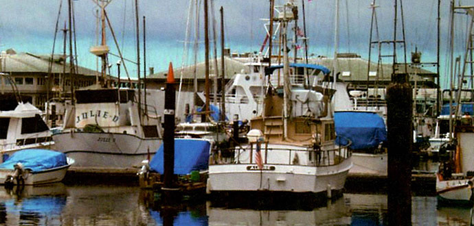
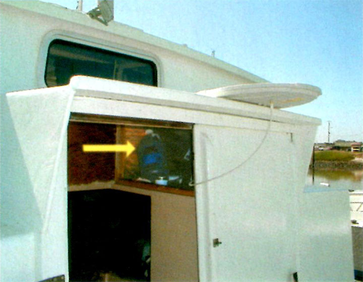
A view from the location of an unintentional GPS jammer across Moss Landing Harbor to the Monterey Bay Aquarium Research Institute. A GPS receiver with its antenna on the other side of the roof was continuously jammed for months.
In April 2001, the captain of the research vessel PT SUR, based in Moss Landing, California, made a radio telephone call from at-sea to one of the authors, stating that signal reception of GPS in the whole of Moss Landing Harbor was jammed. He was advised to contact the U.S. Coast Guard (USCG) and the Federal Communication Commission (FCC). When the problem persisted for another month, we launched an effort at the local level to determine the cause of the jamming.
Moss Landing is a moderate-sized harbor about 100 kilometers south of San Francisco, in the middle of Monterey Bay. It has a mixed fleet of working fishing boats, pleasure craft, and three large research vessels used by the local scientific community.
The Naval Postgraduate School (NPS), with a large program in science and engineering, is located at the south end of Monterey Bay. The Monterey Bay Aquarium Research Institute (MBARI) has its headquarters in Moss Landing and two major research vessels berthed there. This organization supports the Monterey Bay Aquarium and also has a large engineering program, especially in underwater remotely operated vehicles.
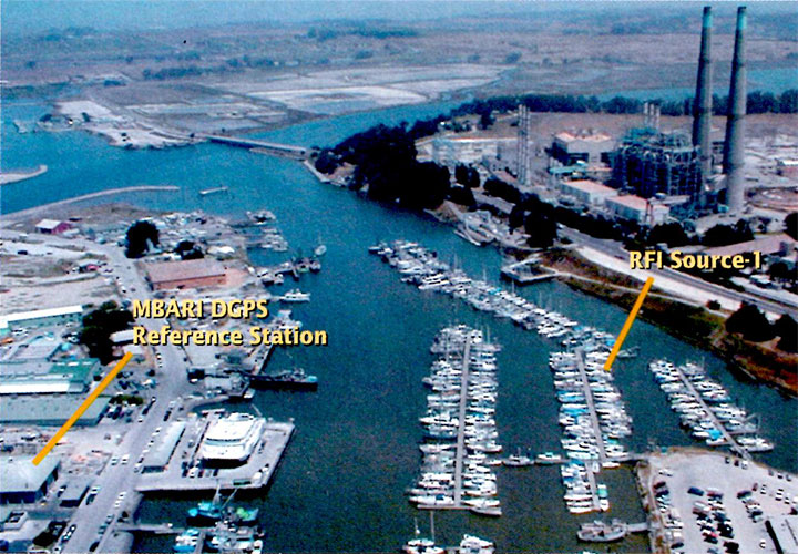
Locations of the RFI emitter and MBARI; power plant upper right.
MBARI has used GPS for precision location of their vessels since the early 1990’s, before the U.S. Coast Guard set up their system of DGPS stations along the coast. MBARI, with assistance from NPS, set up a differential station at their location at Moss Landing, using a UHF data link to send the corrections to their vessels.
After the April jamming report, NPS set up a monitor of the MBARI DGPS corrections to log the number of satellites being tracked. This clearly showed that the station was being heavily jammed. Reports of other GPS users in Moss Landing confirmed that it was a jamming issue and not a faulty receiver.
The jamming had impacted MBARI in several ways, including causing it to loose its GPS-based high-accuracy time reference. It would have caused difficulty at the narrow harbor entrance in fog. In at least two cases it caused small-boat owners to buy new GPS receivers, only to find they still could not get GPS in and around Moss Landing. One of the major ships in the harbor paid for a technician and new equipment to fix the problem, but finally had to turn off GPS in the harbor area, give the alarm that GPS was off line, and use radar only for harbor entrances in bad weather.
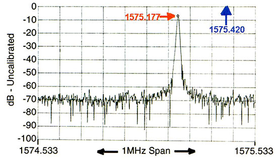
The GPS signal that feeds the MBARI reference station was also distributed to several laboratories and offices in the MBARI headquarters building, through a series of splitters and inline amplifiers. In an office with one of these drops, we set up a high-quality spectrum analyzer to examine the energy in a wide band about the GPS L1 frequency. Because there were several long cables and amplifiers between the antenna and the spectrum analyzer, the signals were not calibrated at the time they were taken. Later the system was calibrated. Figure 1 shows an example of the data recorded with a clear peak from the radio frequency interference (RFI) source many dB above the level of the GPS signals.
Figure 1. spectrum of Source-1 on a spectrum analyzer, VBW 3 KHz, RBW 3 KHz.
Identifying Source-1
We began our search for the source of the jamming radiation in early May, 2001, spending several days looking for it. Two factors complicated the effort: the large number of metal objects that reflected the energy, and the shifting of the frequency of the emitter.
George Badger fabricated a 17-element antenna with about a 30-degree beamwidth and used this with a portable communications receiver, a general purpose radio that fit in a shirt pocket. The initial search drove along the roads in the area and stopped at widely spaced locations to record the peaks of the RFI signal. We found multiple peaks in all locations, coming from the many reflecting structures in the area, including the largest conventional power plant in California.
From its normal location inside the paint locker (see arrow), the antenna jammed all of Moss Landing Harbor and an area at least 1 kilometer out to sea.
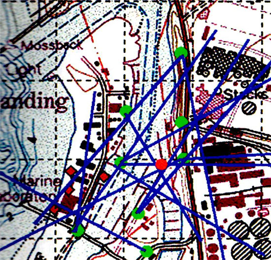
Figure 2 shows the locations where bearings were taken as green circles, and the bearings in blue. The red circle shows the actual location of the emitter. Without the red dot, it is hard to define where the most likely position is. After ruling out the power plant, we decided to look where there were no building or other reflectors.
Figure 2. Search for bearing for Source-1.
Closing In. The team put the spectrum analyzer on a cart along with the small radio, and took them to the dock area. Even then it was confusing. Only by turning off shore power to individual boats could we determine the actual emitter location. The signal stopped and started again as we turned power to the vessel emitting the RFI signal off and on. The photograph, taken by a “kite camera” at about 200 meters, shows the locations of the RFI emitter, MBARI, and the power plant.
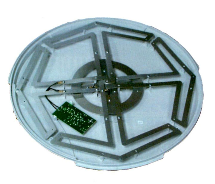
Source-1 with cover open, showing the small preamplifier that jammed GPS.
We contacted the boat owner and gained access, quickly determining that the emitter was a commercially available VHF/UHF television antenna with built-in preamplifier. The antenna was powered by an AC/DC adapter plugged into boat AC power. The preamplifier was thus powered all the time, even when the TV was not on. In fact, the TV was seldom on, and most of the time the TV antenna was in a paint locker inside the locked boat. From this interior location, its emissions jammed all of Moss Landing Harbor and an area at least 1 kilometer out to sea.
The day after we located the jamming antenna, we purchased it from the owner, took it to NPS for study, and informed the Federal Communications (FCC) San Francisco field office. We also distributed a memorandum describing the facts of the case to the U.S. Coast Guard and the GPS Joint Program Office (JPO).
Characteristics of Source-1
At the Naval Postgraduate School, we studied the antenna under controlled conditions and found it to have an internal preamplifier that exhibited unintended oscillations. The unit was normally powered from an inexpensive 12-volt AC/DC converter. In the tests it was powered from both this unit and a battery.
We studied the characteristics of the emission using another spectrum analyzer with its output sent to a waterfall display.
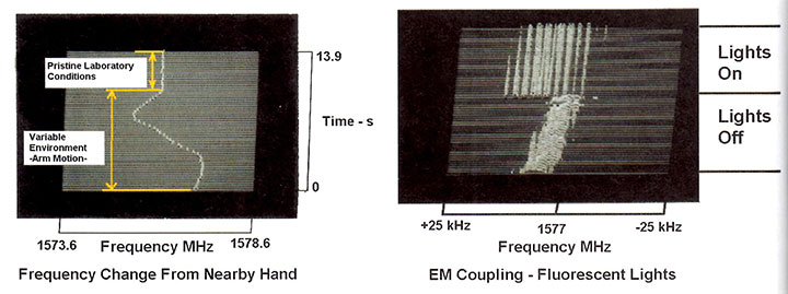
The unit proved extremely sensitive to the physical and electrical environment. We knew this from our search procedure, when modulation on the signal was recognized by its distinctive sound as a boat bilge pump. In an ad hoc experiment, we noted that the frequency varied over 3 MHz when one of us slowly moved his hand about 20 centimeters when it was 3 meters from the antenna. This is shown on the left in Figure 3. When the hand was held still, the frequency was much more stable, as seen by the section at the top of the traces.
Figure 3. Frequency changes in Source-1 caused by environmental factors.
In another case, when running on batteries, the spectral pattern changed considerably when the overhead fluorescent lights were turned on and off. This effect is shown on the right. In order to get the narrow lines in the “lights on” condition, the spectrum analyzer was synchronized to the AC line frequency. We also found that the operation of a low-powered, hand-held transceiver (100 mW) operation at 150 MHz and 450 MHz caused large shifts in the oscillation center frequency.
To better investigate the electromagnetic coupling, we placed the unit in a good screen room. We were interested to see if you needed an external RF field from the lights, for example. It still oscillated, indicating that the oscillation would emit RFI energy just by being turned on. No special external conditions were required.
We obtained several other tests results, but conclude principally that the oscillation was self-exciting and very sensitive to environmental conditions.
The Suspects Multiply
During the hunt for RFI Source-1, NPS monitored the DGPS corrections broadcast by MBARI, automatically recording and plotting the total number of satellites for which corrections were generated every few days. While Source-1 was active, there were no satellites being tracked.
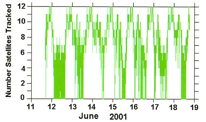
A few days after Source-1 was removed, we again plotted this log. Much to our surprise, there were still long periods when the MBARI GPS receiver was tracking few or no satellites. The MBARI GPS receiver was being jammed during most nights. Figure 4 shows a plot of the number of satellites tracked.
Jamming of MBARI GPS after Source-1 was removed from harbor.
We conjectured that the jamming’s diurnal pattern derived from the temperature sensitivity of the second jammer’s center frequency. This turned out to be correct. The jamming was correlated with temperature and ended most days before 11 am.
This told us that we would have to hunt the source location at night and early morning.
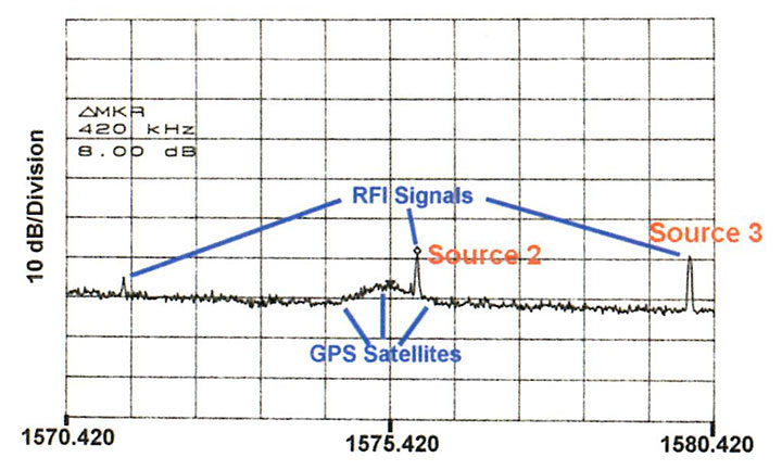
Field Operations. The San Francisco FCC field office sent a team several times to Moss Landing to hunt for Source-2, and on several days both MBARI and NPS assisted. The MBARI high-quality spectrum analyzer monitored the signal from the laboratory this time, showing that its frequency moved during the morning hours and its level decreased as the temperature rose. We sent this frequency via cell telephone to the mobile team in the harbor seeking the RFI source. Figure 5 shows a typical early morning spectrum taken after removal of Source-1. Again the hunt was not easy.
Figure 5 shows a typical early morning spectrum taken after removal of Source-1. Several signals are visible in this spectrum, in addition to a broad peak in the middle from the GPS satellites. This was not seen in the spectra taken earlier because Source-1 masked it. The peak in the GPS band comes from Source-2.
On the second FCC trip to Moss Landing Harbor, the signal in the GPS band had dropped by 10 dB in the late morning. We decided to hunt for the source of of a higher-level signal just outside the GPS band. This is the line at about 1580 MHz shown in Figure 5. The combined group quickly located the source of this signal. Again the combined use of a spectrum analyzer and portable receivers with a narrow-beam antenna was important. We also monitored the frequency on the spectrum analyzer inside MBARI and relayed the current value to the field team by cell telephone.
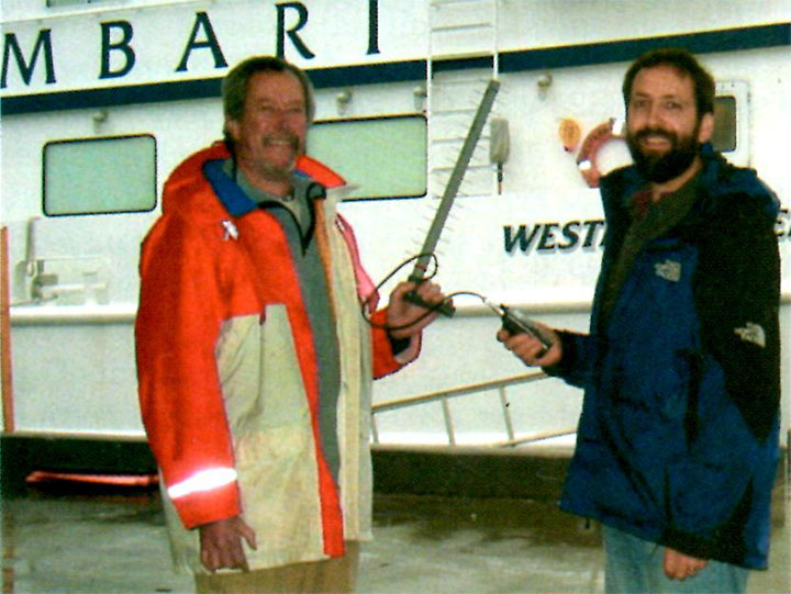
Authors Badger and McGill with a 13-element yagi antenna and communications receiver used in dockside search.
In the end, turning the power on and off to a few boats and correlating this with the RFI signal identified the culprit. It turned out to be a another commercially-available UHF/VHF television antenna on a boat, one dock over from Source-1. When it was turned off, only the line near 1580 MHz went away. Therefore we labeled this perpetrator as Source-3. This owner returned the unit to the place of purchase for a replacement.
The FCC has determined that the preamplifiers in Source-3 and Source-1 came from the same factory, which sold units to at least four well-known U.S. brand names of consumer electronic equipment. The bad units apparently began with a design change in late 2000; the number of units sold is not known to the authors.
Suspect Roundup. It is now clear that there were at least three signals capable of jamming GPS in the Moss Landing Harbor area. Two were located and removed by a coordinated effort of MBARI, NPS and the FCC.
The FCC made a few more attempts to locate Source-2 during the summer, but its level was lower with the higher temperatures. In the fall of 2001, the FCC succeeded in locating Source-2. It again turned out to be a VHF/UHF television antenna with preamplifier.
Calibration
There were a large number of spectra taken in the MBARI office. The signal came in the DGPS reference station antenna and went through two splitters and one inline amplifiers in the approximately 80 meters of low loss cable before emerging in the engineering office. Rather than examining the individual elements, we decided to calibrate the entire system.
A calibrated source was sent to a standard antenna about 2 meters from the antenna. The same analyzer used to acquire data on the RFI sources was configured as it had been for the experimental data. The antenna manufacturer supplied beam patterns for the antenna. In this way, the signals were now calibrated at the level outside of the antenna.
There still is an uncertainty about the space loss and antenna beam pattern gain/loss for actual sources. The latter can be found for the signals located, but not unknown signals such as Source-2. Accordingly the data were calibrated as a power level at the outside of the MBARI antenna.
Comparison to a RFI Specification
The composite Figure 6 shows one spectra, now calibrated to dBm outside the antenna, and a specification for the RFI levels. This is the specification that aircraft GPS receivers used for GPS landing systems must meet. The values measured from several other spectra taken at MBARI have also been plotted on this figure. Clearly these signals were above the narrow band limits by amounts from 3 to 24 dB.
Source-1 had the highest level at -96 dBm. Its location is known to have been 325 meters from the MBARI antenna. It was at an elevation angle of -2.5 degrees. While the beam pattern of Source-1 is unknown, if it were omni-directional, it would exceed this FAA specification at a range of 50 kilometers or more. It is known to have caused marine GPS receivers to lose lock out to 3 kilometers. The effective power of this source can only be bounded from the data available. It is at least a few milliwatts.
Source-2 varied in frequency and level. While on top of the L1 frequency, it had a level of -106 dBm. Source-3 had a level at MBARI of -99 dBm. While it was about 12 MHz from the center of L1, the variation in manufacture is likely to have produced units with emissions much nearer L1.
Conclusions
In one small California harbor, at least three emitters capable of jamming commercial GPS receivers were present. Two were located and removed by the authors. They were active UHF/VHF TV antennas and appeared to have the same internal preamplifier. The FCC has located and removed the third.
Locating these sources proved difficult. It required a spectrum analyzer with averaging capabilities on a broadband antenna to track the jammer frequency and a narrow-band portable receiver with a directional antenna to localize it. Even then, a power on/off test was needed to verify that the source had indeed been found.
The existence of the jamming was well-known in Moss Landing Harbor, and reported at least once to appropriate agencies. However, the problem persisted until local engineers and scientist hunted down the worst offender. Clearly there was a system problem with reporting and removal of RFI sources. More education of harbor masters or some other change needs to be implemented to deal more quickly with this type of problem.
Acknowledgement
Gary Thurmond, a retired MBARI engineer, provided technical advice and participated in the location of Source-1 and took the aerial photograph of Moss Landing Harbor.
James R. Clynch is a research professor at the Naval Postgraduate School in Monterey, California, and has worked for 30 years in the use of satellite navigation systems for precision positioning and to study propagation effects. He has a PhD from Brown University.
Andrew A. Parker, Richard W. Adler, and Wilbur R. Vincent are research professors in the Department of Electrical and Computer Engineering at the Naval Postgraduate School. Their PhDs are from University of Maryland, Pennsylvania State University, and Michigan State University, respectively.
Paul McGill is an electrical engineer and George Badger a microwave technician at the Monterey Bay Aquarium Research Institute.
Manufacturers
The MBARI differential station uses a Trimble RL 4000 GPS receiver. The waterfront search employed a Hewlett Packard 8562 spectrum analyzer and an An ICOM IC-R3 5 communications receiver. A Hewlett Packard 8562E spectrum analyzer was used at NPS to study the emissions. Trimble Navigation provided a beam pattern for the specific antenna used on the MBARI roof, and the antenna used for calibration.