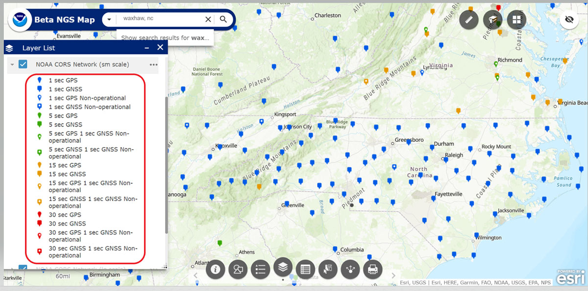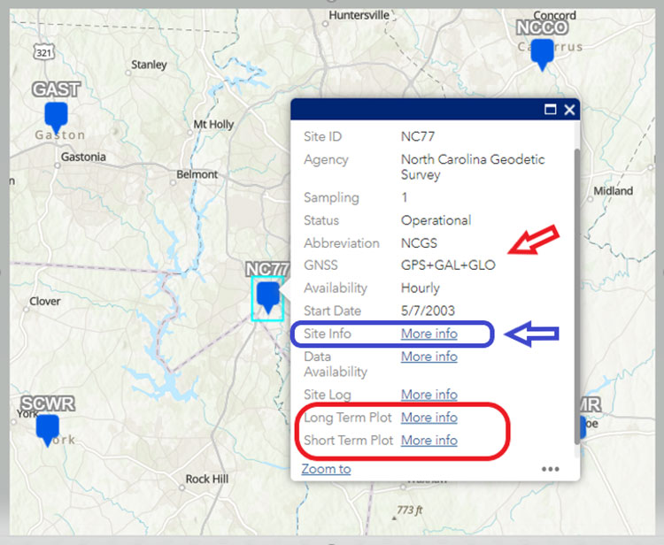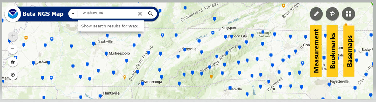
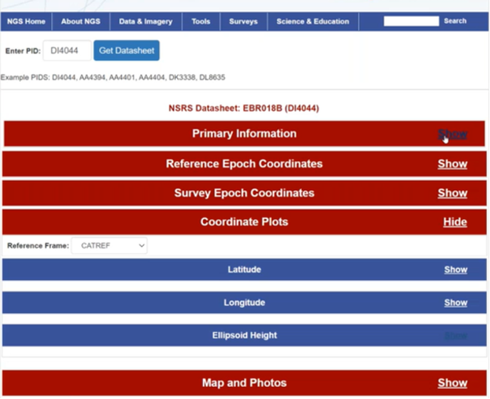
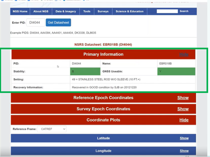
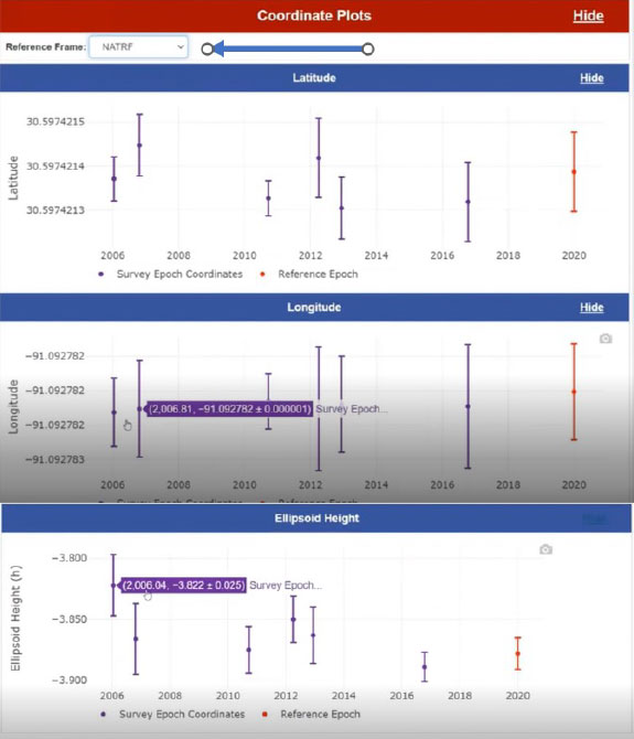
In my last newsletter, I highlighted the release of a beta version of a new NOAA CORS Network (NCN) Station Web Page. As demonstrated in my newsletter, each CORS in the NCN has its own page with data, metadata, maps and photos for that station displayed in a modular layout so information is easily found all in one location. This past month, I had the privilege of participating in a meeting with representatives from the American Association for Geodetic Surveying (AAGS), the National Society of Professional Surveyors (NSPS) and the National Geodetic Survey (NGS). As a Past President of AAGS and the current Chair of the AAGS Membership Committee, I participate in these quarterly meetings.
AAGS aims to lead the community of geodetic, surveying, and land information data users through the 21st century. AAGS members develop new educational programs, including presentations, seminars, and workshops on topics related to geodetic surveying; and articles and papers that inform the membership of the latest scientific and technological developments and how to implement them in the most cost-effective and efficient manner.
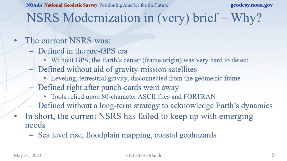
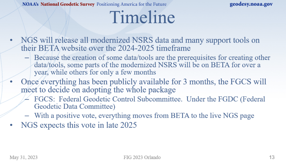
In my previous newsletters, I have reminded everyone that time is running out to obtain a working knowledge of the new, modernized National Spatial Reference System (NSRS). The release of the new, modernized NSRS is only about a year away. As of July 2024, NGS plans to have a beta version of the new, modernized NSRS available around the summer of 2025 for users to test and evaluate new products and services. After enough testing has been performed, the new, modernized NSRS will be officially published – probably in early to mid-2026.
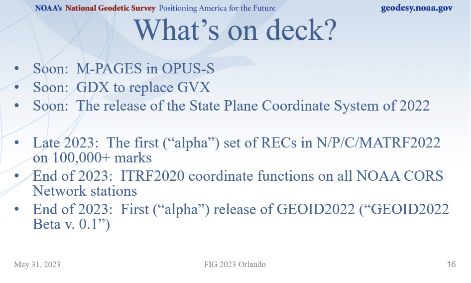
At the meeting, NGS highlighted some new products on its Alpha Preliminary Products site. The alpha site provides products that are useful for individuals who want to obtain a better understanding of the products that will be distributed as part of the new, modernized NSRS.
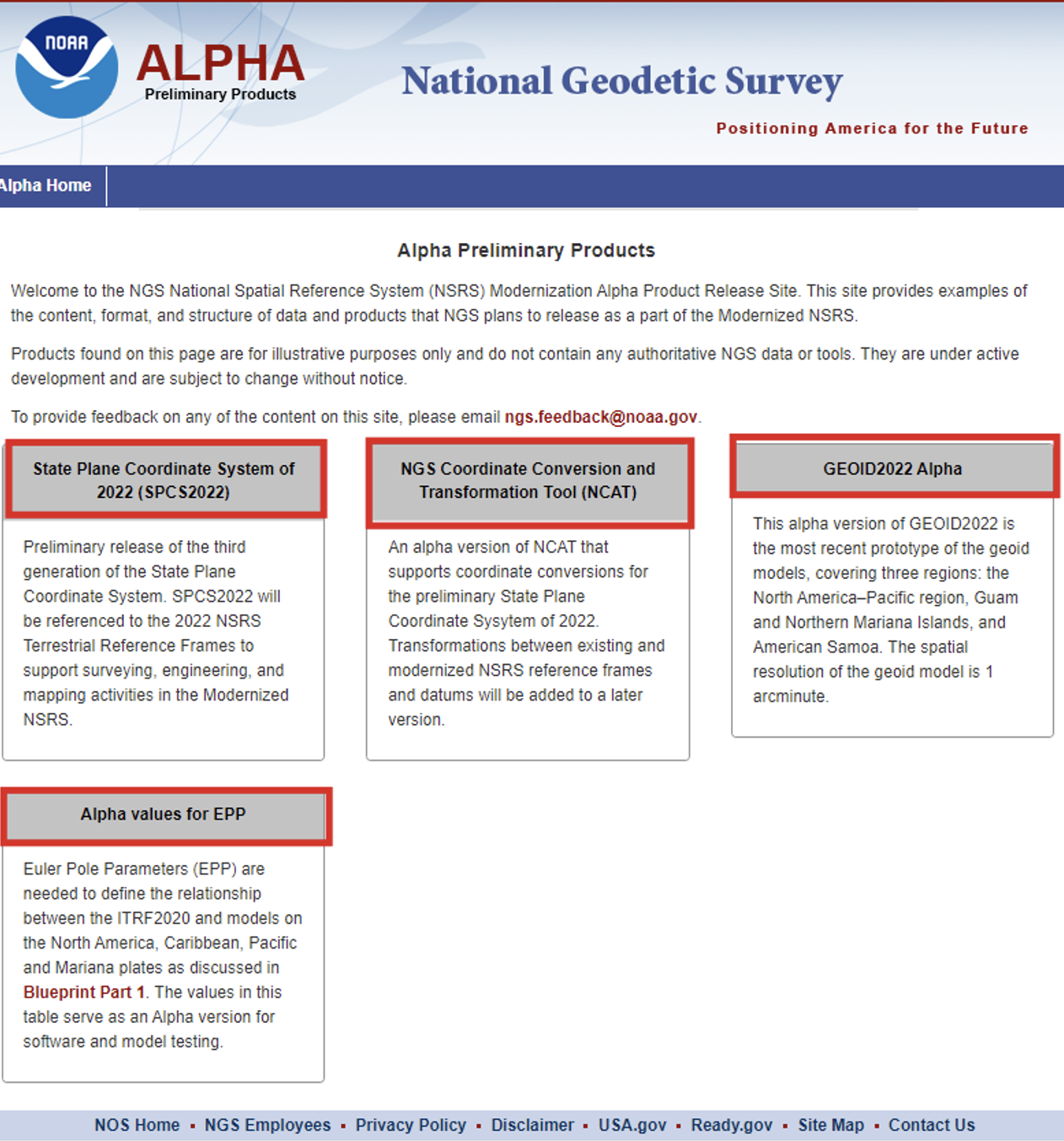
Some of my previous newsletters have discussed the Alpha product concept. My September 2023 newsletter highlighted the first two Alpha products; that is, State Plane Coordinate System of 2022 (SPCS2022) and NGS Coordinate Conversion and Transformation Tool (NCAT). As of June 2024, two more products have been added to the Alpha Preliminary Products site – “GEOID2022 Alpha” and “Alpha Values for EPP.” The State Plane Coordinate System of 2022 (SPCS2022) is probably the most important to land surveyors. There are significant changes between the SPCS2022 and the State Plane Coordinate System of 1983 (SPCS83). I will highlight the latest options in the alpha site later in this newsletter.
First, I want to bring attention to the importance of ensuring that the state’s legislation is modified or rewritten, if required, to include that the current horizontal and vertical datums are being replaced with the new, modernized NSRS. The “Learn More” button on the SPCS2022 Alpha site provides information about legislation.
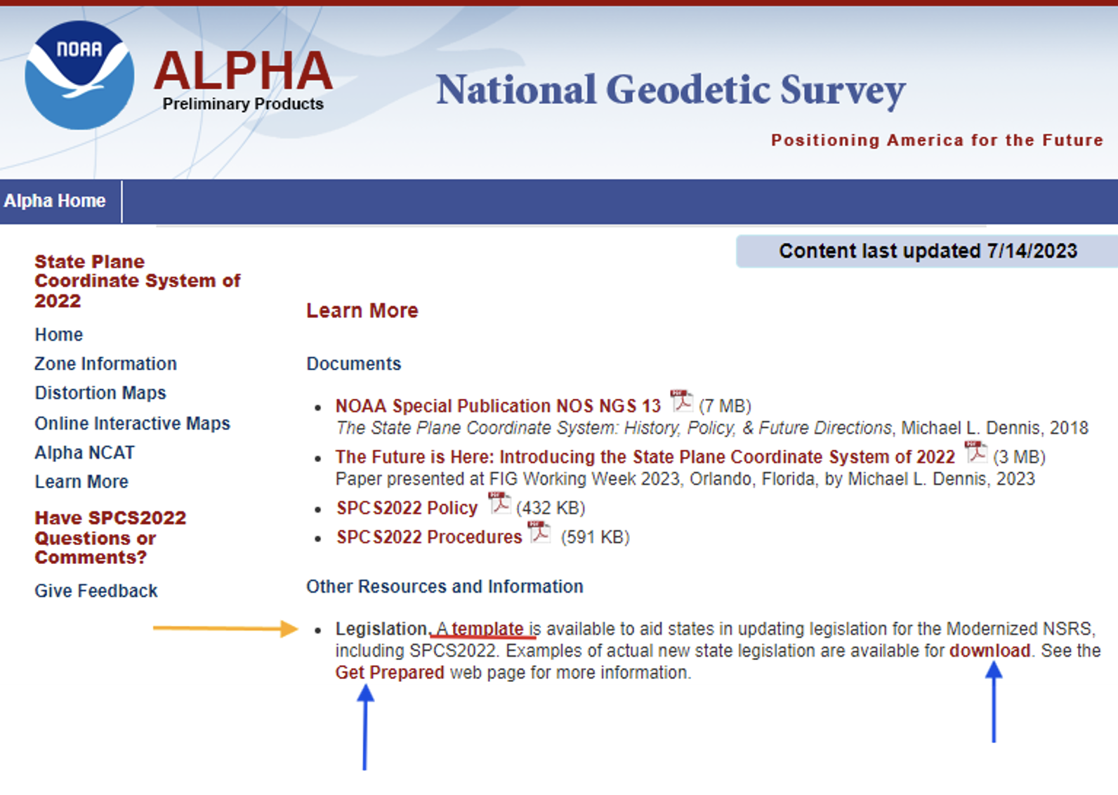
On the “Learn More” site, NGS provides an SPCS legislation template.
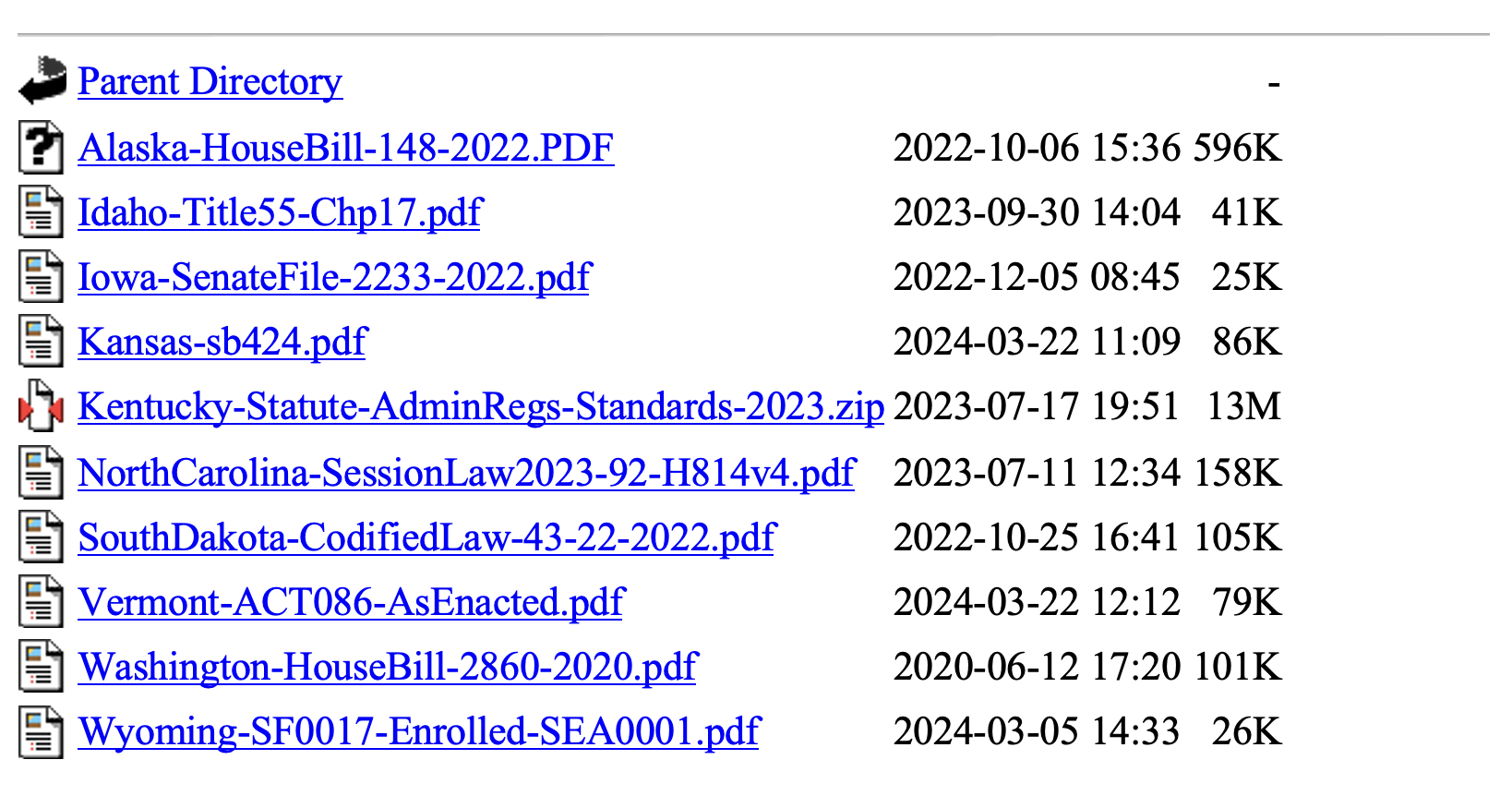
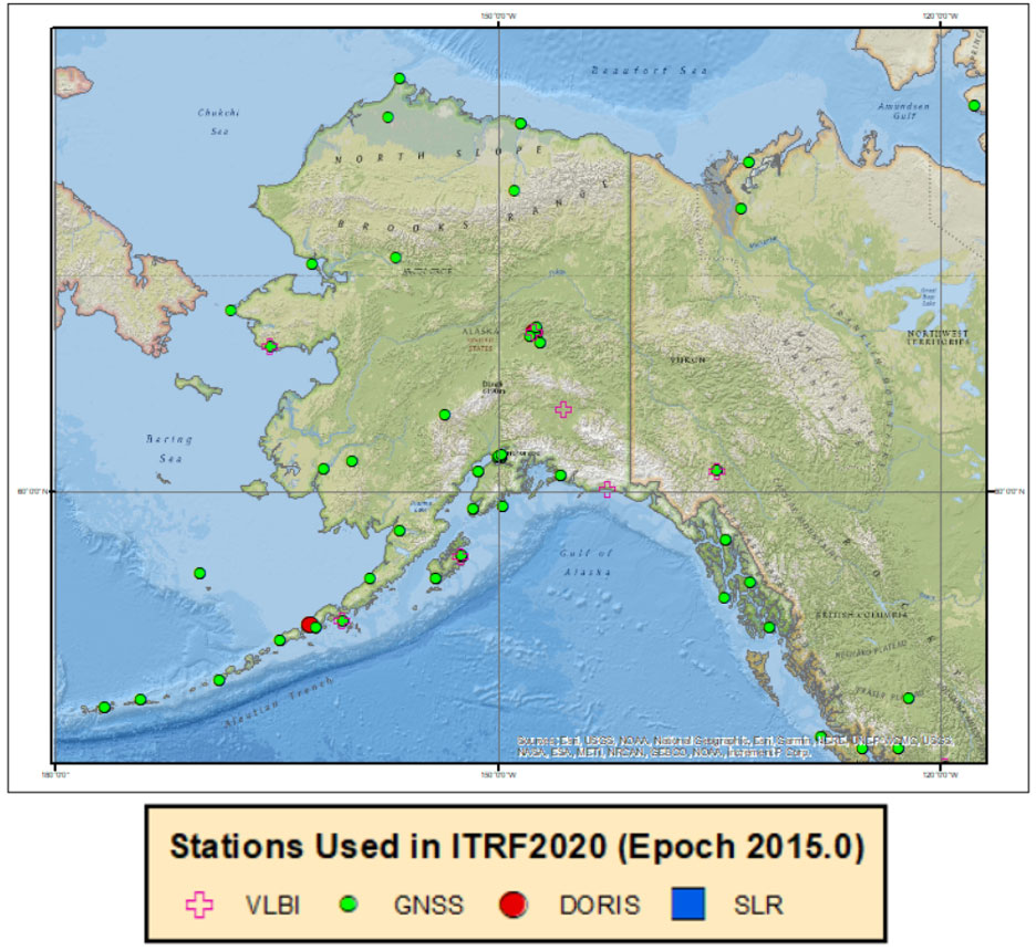
Per personal communication with Michael Dennis, Ph.D., NGS SPCS2022 Manager, as of June 26, 2024, the following 12 states have have enacted into law NSRS modernization: Alaska, Idaho, Iowa, Kansas, Kentucky, Louisiana, Nebraska, North Carolina, South Dakota, Vermont, Washington, and Wyoming.
Users can download examples of actual new state legislation here.
During the joint AAGS/NSPS/NGS meeting, Tim Birch, the executive director of NSPS, said that anyone who has questions about updating legislation for the new, modernized NSRS, including SPCS2022, can contact him directly. NSPS has experience working with agencies and individuals to develop legislation as indicated in the following statement on the NSPS website.
“We are the voice of the professional surveying community in the US and its territories. Through its affiliation agreements with the respective state surveying societies, NSPS has a strong constituency base through which it communicates directly with lawmakers, agencies, & regulators at both the national and state level. NSPS monitors and comments on legislation, regulation, & policies that have potential impact on the activities of its members and their clients, and collaborates with a multitude of other organizations within the geospatial community on issues of mutual interest.”
Tim’s contact information is provided on the NSPS home webpage: Staff List – National Society of Professional Surveyors (nsps.us.com).
As previously stated, the two latest alpha products are the “GEOID2022 Alpha” and “Alpha Values for EPP.” My December 2017 newsletter discussed GEOID 2022 and the North American-Pacific Geopotential Datum of 2022 (NAPGD2022), and my February 2022 newsletter discussed the Euler Pole Parameters process and use in the new, modernized NSRS.
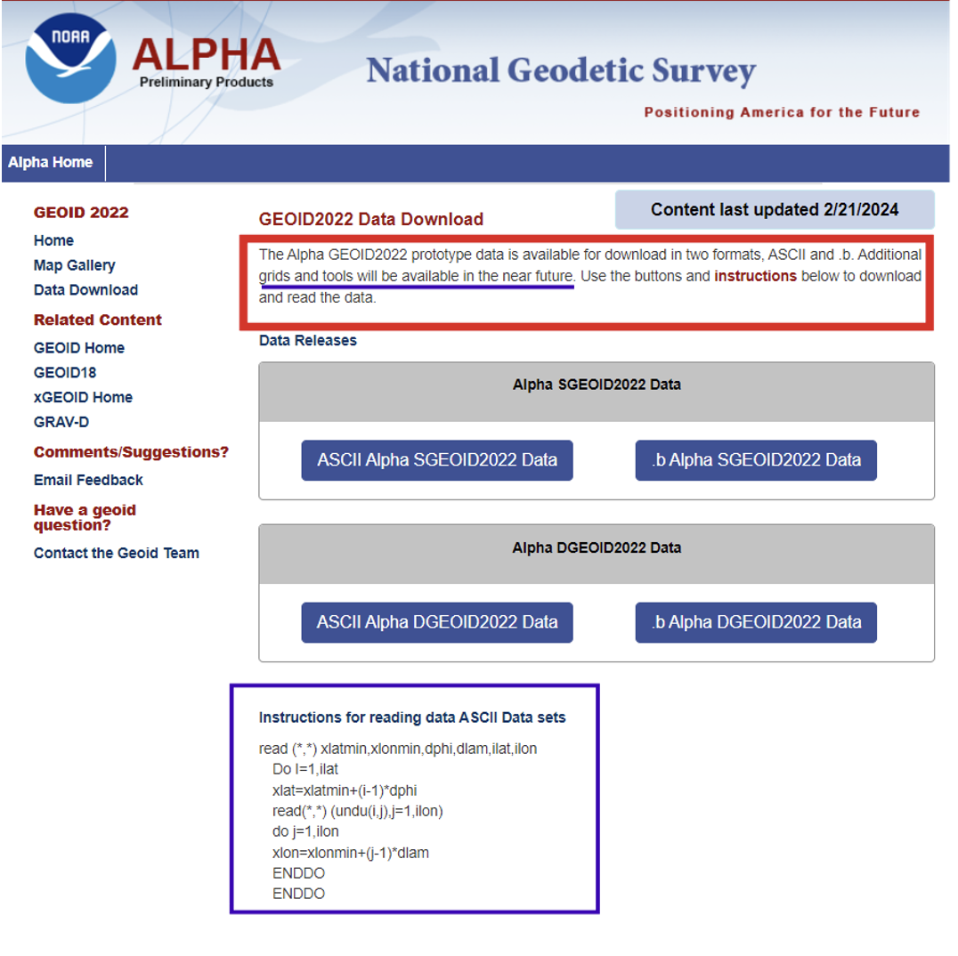
The GEOID2022 Alpha page provides a version of GEOID2022, which is the most recent prototype of the geoid models. The reference ellipsoid is Geodetic Reference System 1980 (GRS 80, but the geometric reference frame is ITRF2020). The Alpha GEOID2022 prototype data is available for download in two formats, “ASCII” and “.b.” There is a static component (SGEOID2022) and a dynamic component (DGEOID2022). These grids will be useful to programmers who want to develop and test their systems. Additional grids and tools will be available in the future.
Technical Details of the Alpha prototype of GEOID2022
GEOID2022 alpha is the last prototype of GEOID2022. It covers three regions: the North America–Pacific region, Guam and Northern Mariana Islands, and American Samoa. The spatial resolution of the geoid model is 1 arcminute. The geoid heights, which are in the tide-free system, are with respect to the reference ellipsoid of the Geodetic Reference System 1980 (GRS80) in the ITRF2020 geometric reference frame. GEOID2022 alpha includes static and dynamic components for the geoid heights. For detailed fundamental parameters of the geoid model, refer to NOAA Technical Report 78.
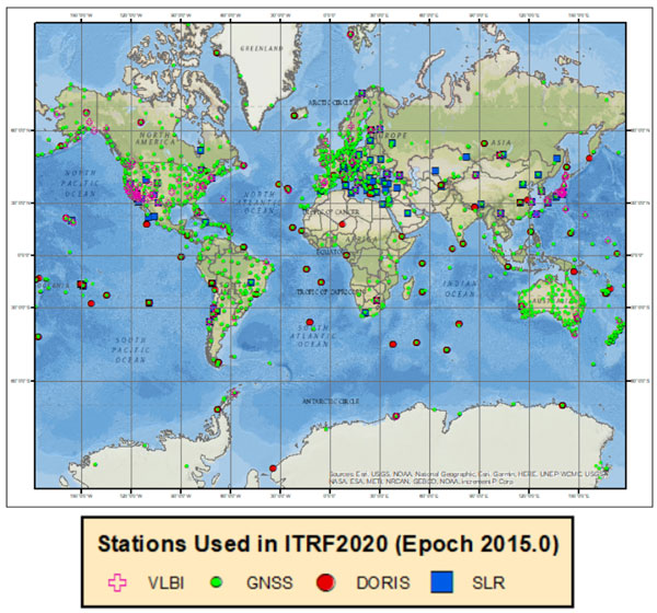
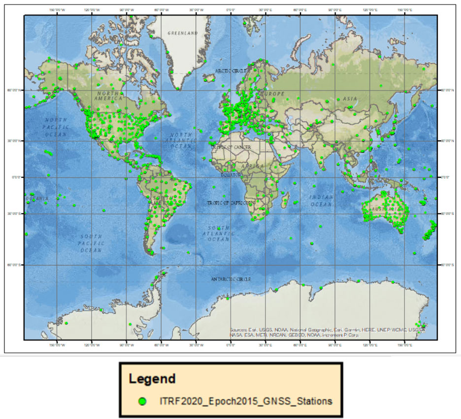
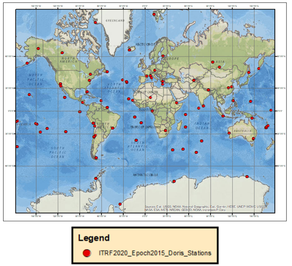
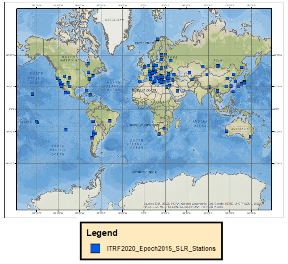
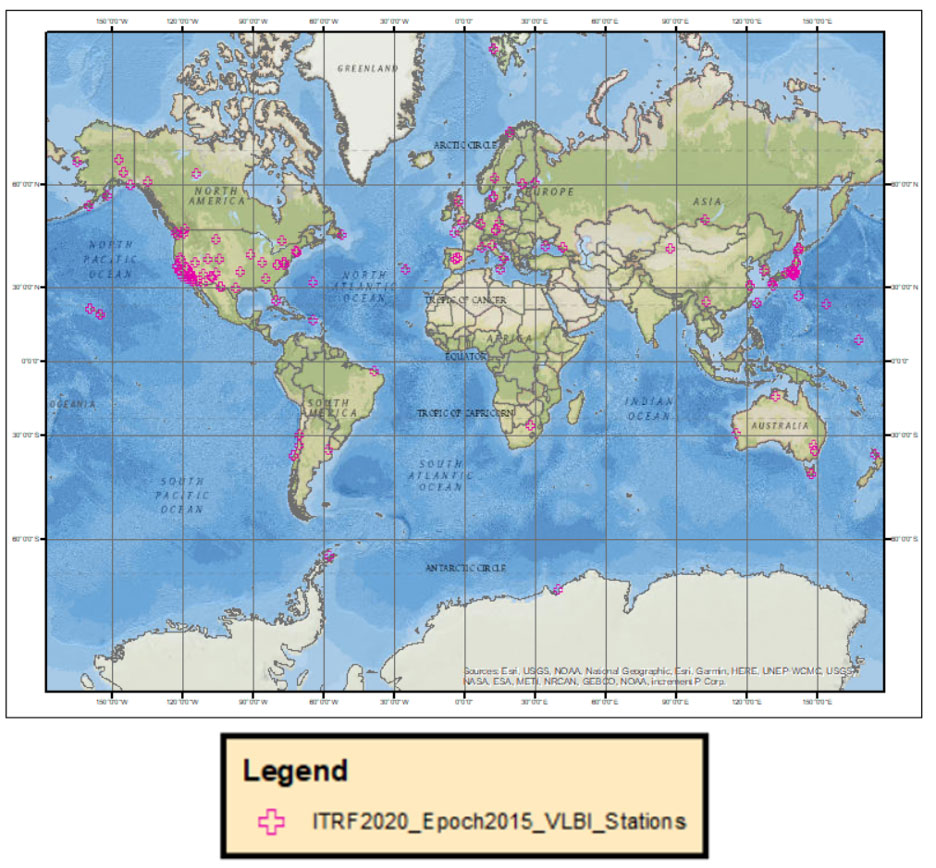
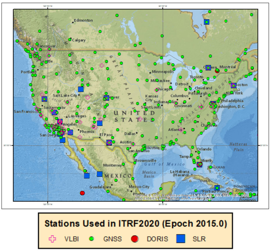
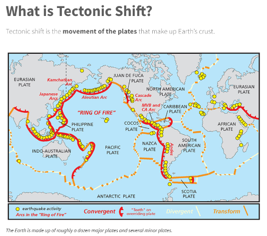
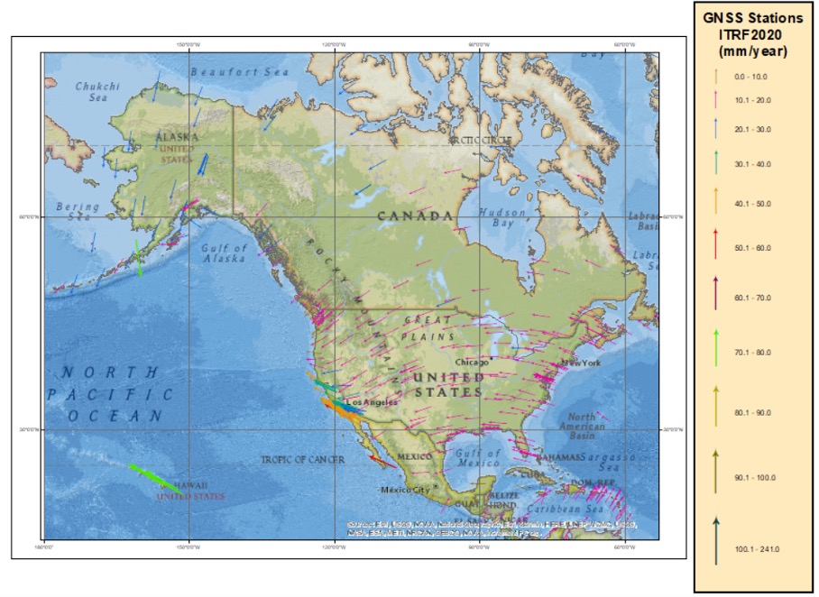
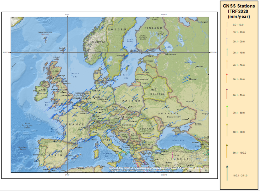
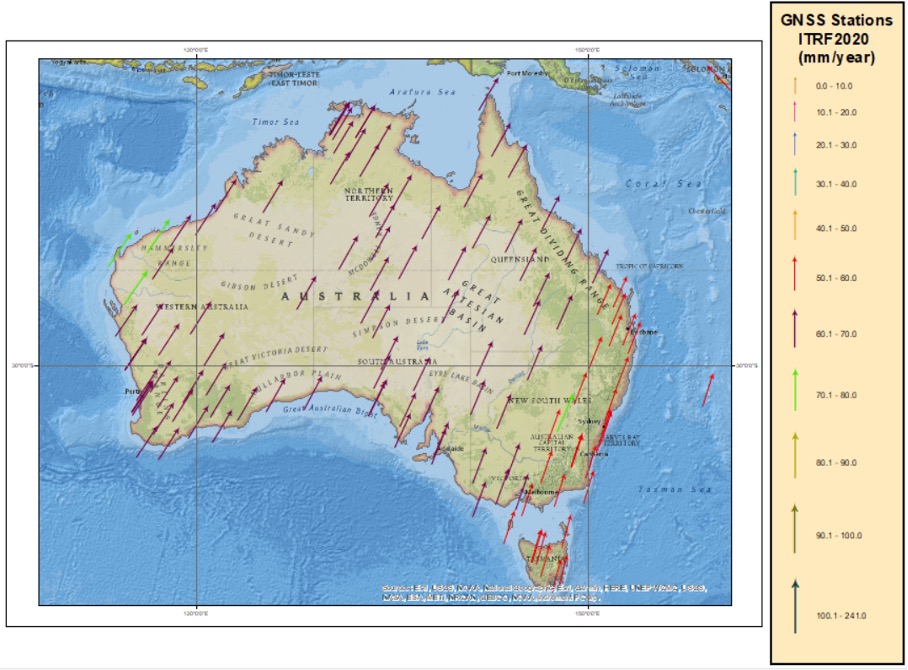
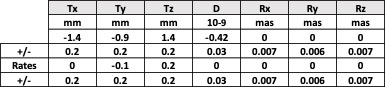
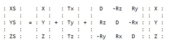
The Alpha EPP site provides the Euler Pole Parameters (EPP) that are needed to define the relationship between the ITRF2020 and models on the North America, Caribbean, Pacific and Mariana plates as discussed in NGS’s Blueprint Part 1 document.
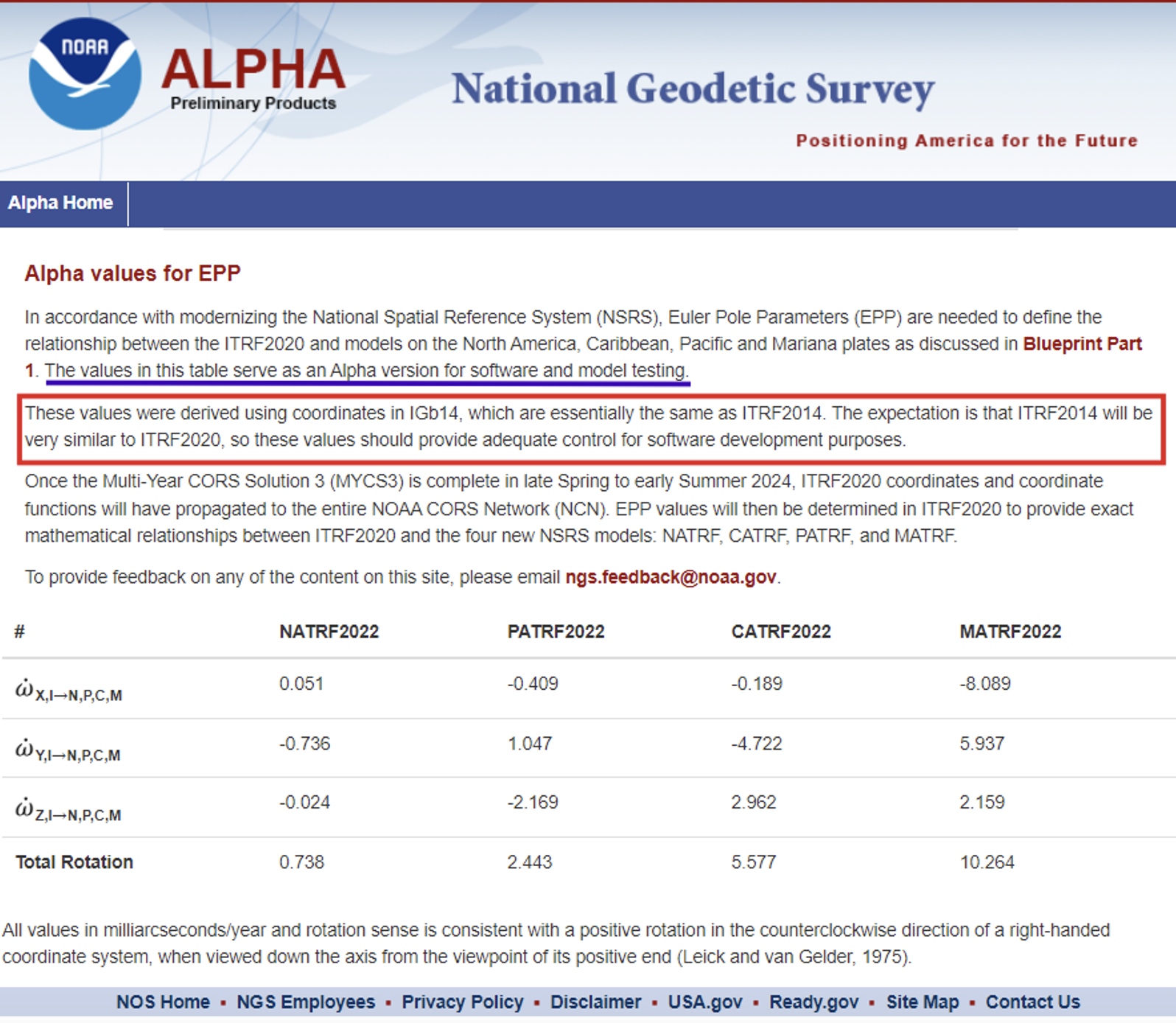
As stated in Blueprint Part 1, NGS will define the official relationship between ITRF2020 and the four NSRS TRFs through equation 59, using the rotation matrix in equation 58 resulting in equation 60.
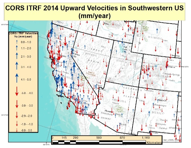
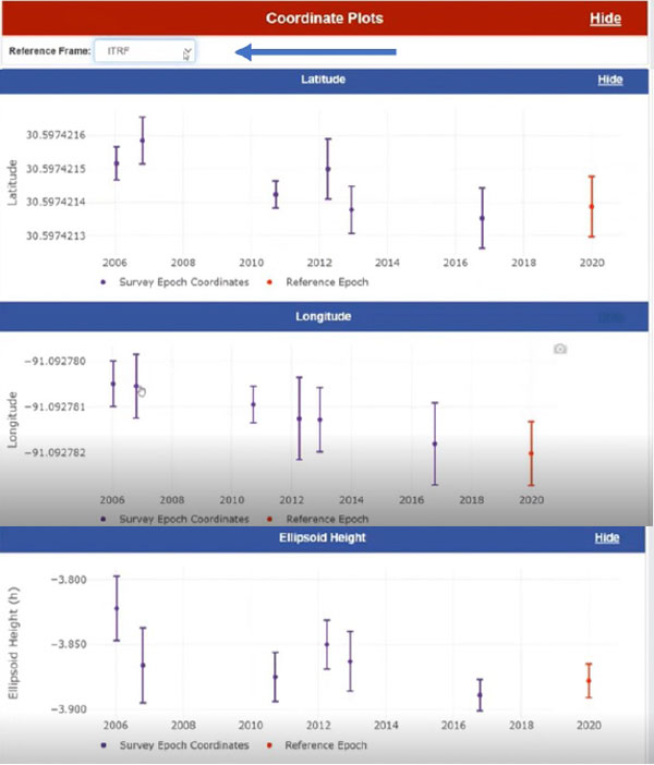
I programmed this using a simple Excel spreadsheet to compute some of the potential changes between epochs for North Carolina. They were very similar to the ones that I depicted in my February 2022 newsletter that discussed the Euler Pole Parameters process and provided plots depicting the movement.

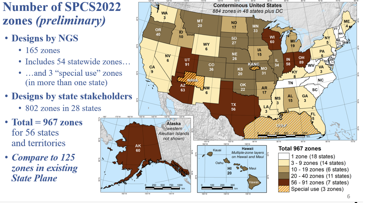
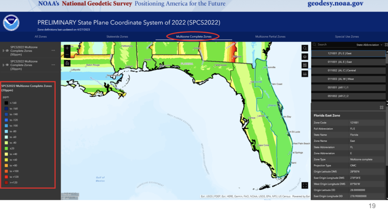
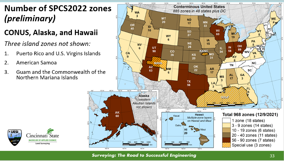
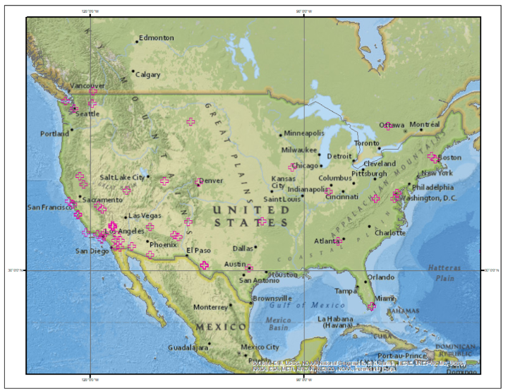
I would like to highlight the latest information available on the State Plane Coordinate System of 2022 alpha site. As previously stated, in about a year, the new, modernized NSRS will be available as a beta product. Users must get prepared by accessing NGS’s alpha products as well as taking the opportunity to provide feedback to NGS to improve their products and services. The Online Interactive Maps page provides information about the zones for every U.S. state and territory.

Clicking on the Online Interactive Maps link opens a NOAA ArcGIS online website that provides information about the Alpha State Plane Coordinate System 2022 preliminary zone designs. I have highlighted a few items that may be of interest to users.
The site provides a description of the site, links to various types of zones, links to data sources and information about distortion.

Clicking on the link for zone definitions provides a list of zones and their parameters. This same information is also provided when users click on a zone on the map. I will demonstrate this later in this newsletter.
Per personal communication with Dennis, as of June 26, 2024, seven states have some or all their SPCS2022 zone definitions formally finalized, consisting of 205 out of the 965 zones (the total number of zones is still preliminary):
- Alaska (partial coverage multizone layer)
- Arizona (both multizone layers)
- Idaho (both multizone and statewide)
- Kentucky (both multizone and statewide)
- North Carolina (statewide zone; it has no other zones)
- South Dakota (both multizone and statewide)
- Wisconsin (multizone)
Dennis informed me that the information on the alpha SPCS2022 Experience has been updated. He told me that the total number of zones decreased from 967 to 965, but based on coordination with the International Association of Oil & Gas Producers (IOGP) Geodesy Subcommittee the number may eventually increase to 972 (more about that in a future newsletter).
He stated that his goal is to finalize the zone definitions by the end of this calendar year or early 2025. Users should keep checking the alpha site.
Dennis mentioned that the website now offers a new feature that provides the distortion value when users click on the map. A nice thing about that is the site can be used on a smartphone, allowing users to obtain real-time distortion information from their location.
Clicking on the link titled “View” in the upper right corner of the box brings up a map that depicts the SPCS2022 zones.

When you click on the note about the ALPHA being preliminary, the map underneath appears where the user can select the type of maps they wish to review.
The following options are available: All Zone Layers, Statewide Zone Layers, Multizone Complete Layers, Multizone Partial Layers, and Special Use Zone Layers.
Users can use their mouses or the “+” button on the left-hand side” to zoom to a particular region, or use the search button on the right-hand side to select a State or zone.


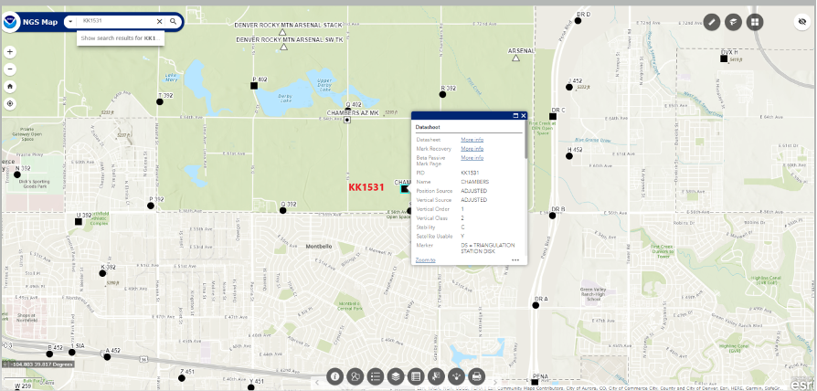
Information about a particular zone pops up by clicking on a point on the map.

Each zone provides links to other features based on the location of the point selected on the map.
The image below provides the distortion in ppm for the point selected on the map.


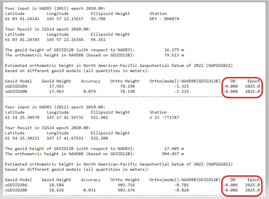
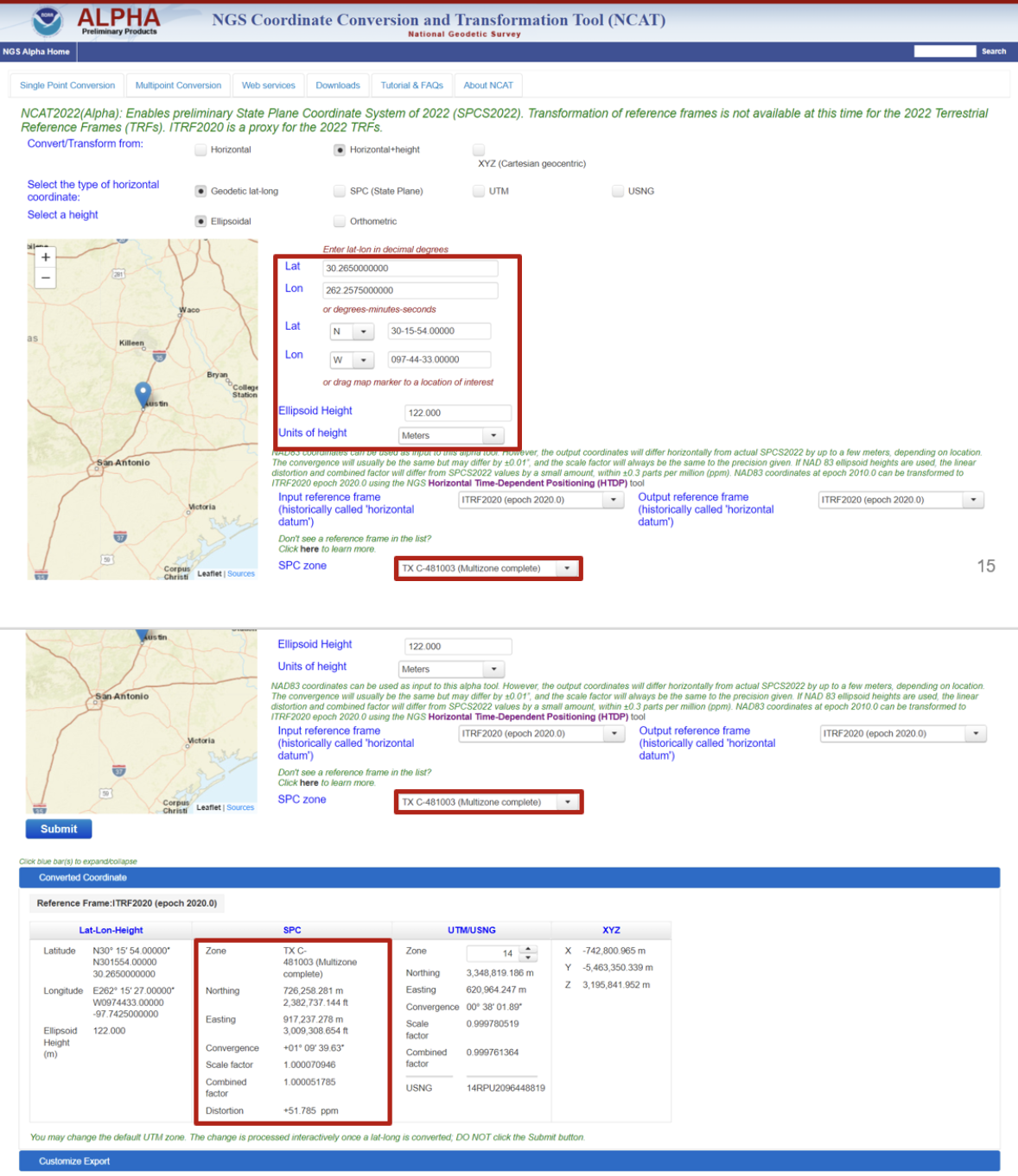
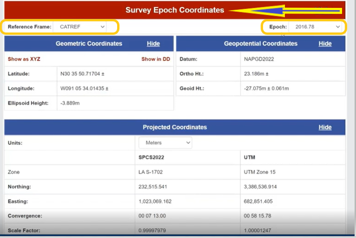
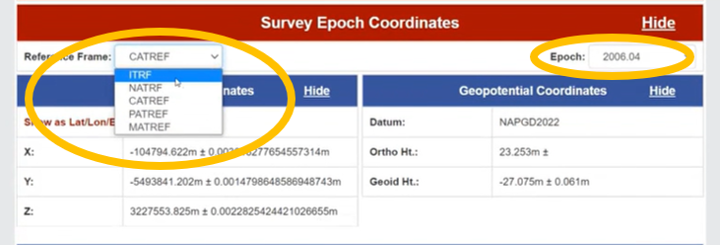
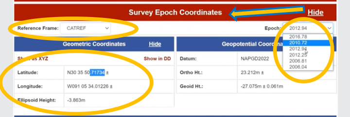
The Alpha NCAT site can be used to obtain an estimate of the changes between SPCS83 and SPCS2022. It should be noted that all values will be in meters (m) and international feet (ft).
International feet may be new to some surveyors who were previously using the U.S. survey feet in SPCS83. The U.S. survey foot will not be used with the NSRS, including SPCS2022 coordinates. NGS and the National Institute of Standards and Technology (NIST) have taken action to deprecate the U.S. survey foot. What does that mean?. NIST has the following statement on its website: “Beginning on January 1, 2023, the U.S. survey foot should be avoided, except for historic and legacy applications, and has been superseded by the international foot.” This means that NGS will not be publishing SPCS2022 in U.S. survey feet but all historic products and services such as SPCS83 will still be provided in U.S. survey feet (sft) and international feet (ift).
More information and resources about the deprecation of the sft are listed below (personal communication from Dennis):
- The official announcement is the final determinationFederal Register Notice (FRN) on deprecation of the sft issued on 10/5/2020. It was jointly issued by the National Institute of Standards and Technology (NIST) and NGS. I encourage everyone concerned about this topic to read it closely and in its entirety; it can likely answer most questions. The FRN includes information on the continued use of sft for legacy applications (such as SPCS 83). That is stated in the last paragraph of the “Notice of Final Determination” section; in items #1 and #2 in the “Counterpoints to Feedback Expressing Opposition”section; and in the second paragraph of the “Implementation Summary and Actions” section.
- The legacy issue is also addressed in the 10th FAQon the NIST website and in the 11th FAQon our “new datums” FAQs web page.
- The 40 states that officially adopted the sft for SPCS 83 are listed in Table C.1 of Appendix C of NOAA Special Publication NOS NGS 13, “The State Plane Coordinate System History, Policy, and Future Directions.”
- Although the final determination FRN is itself not a law, Congress has passed several laws giving NIST the authority to maintain national standards of measurement. These and other related federal laws are given in the initial sft FRNissued on 10/17/2019.
- An NGS webinar given on 11/10/2022 addresses the deprecation of the sft in the context of state plane. Two previous NGS webinars also provide additional background and historical information on the sft, one given on 4/25/2019 and the other on 12/12/2019.


This newsletter highlighted the products on NGS’s Alpha Preliminary Products site. The alpha site provides products that can be useful for individuals to obtain a better understanding of the products that will be distributed as part of the new, modernized National Spatial Reference System (NSRS). NGS is providing these products on an alpha site so that they can get feedback from users. I would encourage all users to access the alpha sites and provide comments to NGS so that their products and services better meet the needs of the surveying and mapping community.
Welcome to the NGS National Spatial Reference System (NSRS) Modernization Alpha Product Release Site. This site provides examples of the content, format, and structure of data and products that NGS plans to release as a part of the Modernized NSRS.
Products found on this page are for illustrative purposes only and do not contain any authoritative NGS data or tools. They are under active development and are subject to change without notice.
To provide feedback on any of the content on this site, please email [email protected].


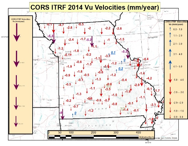
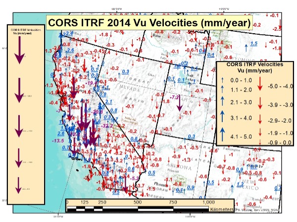
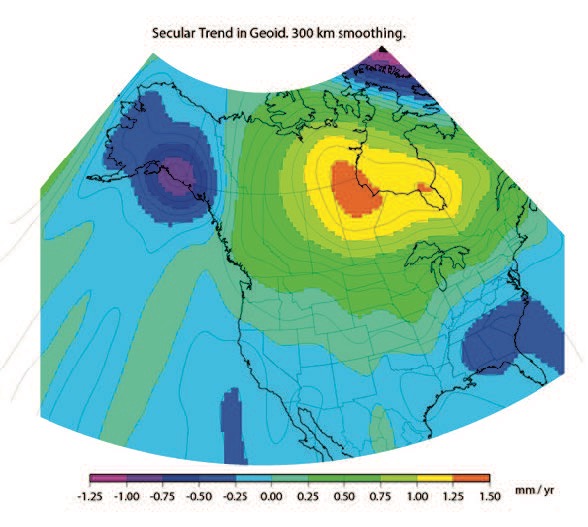
![Figure 32: Geoid rate over CONUS based on the GSFC mascon model [mm/yr] (Image: NOAA)](https://stage.globalpositioningnews.com/wp-content/uploads/2022/05/Geoid-rate-CONUS.jpg)
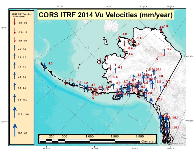
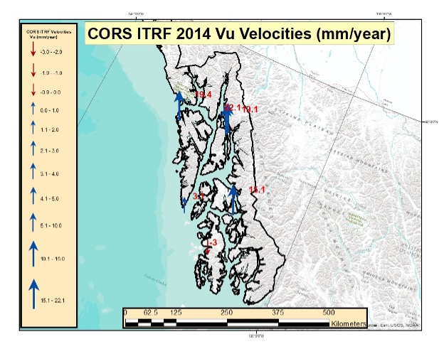
![Figure 33: Geoid rate over Alaska from GSFC mascon model [mm/yr] (Image: NOAA)](https://stage.globalpositioningnews.com/wp-content/uploads/2022/05/geoid-rate-alaska.jpg)