Tag: PNT Corner

  • Monitoring earthquakes, eruptions and avalanches to mitigate risk

    Monitoring earthquakes, eruptions and avalanches to mitigate risk

    On Feb. 6, a magnitude 7.8 earthquake struck Turkiye and northern Syria creating enormous damage throughout both countries.
    On Feb. 6, a magnitude 7.8 earthquake struck Turkiye and northern Syria creating enormous damage throughout both countries. (Image: mustafaoncul/iStock /Getty Images Plus/Getty Images)

    Geographical information of urban areas is critical because it forms the basis for planning, intelligent urban modeling and disaster mapping and management. For many decades, ground surveys and aerial photographs were used as the primary tools for collecting this data. Starting in the 1990s, these methods were replaced by such advanced remote-sensing technologies as synthetic aperture radar (SAR) and ground-based interferometric radar (GBIR).

    This article explores the use of software-defined radio (SDR) platforms for acquiring high-resolution SAR/GBIR images, including:

    • How low-cost commercial-off-the-shelf SDR platforms can be used to realize complex systems for acquiring images and processing measurements.
    • How different specifications of SDRs make them suitable for use in SAR applications.

    Hazard Monitoring in Urban Areas

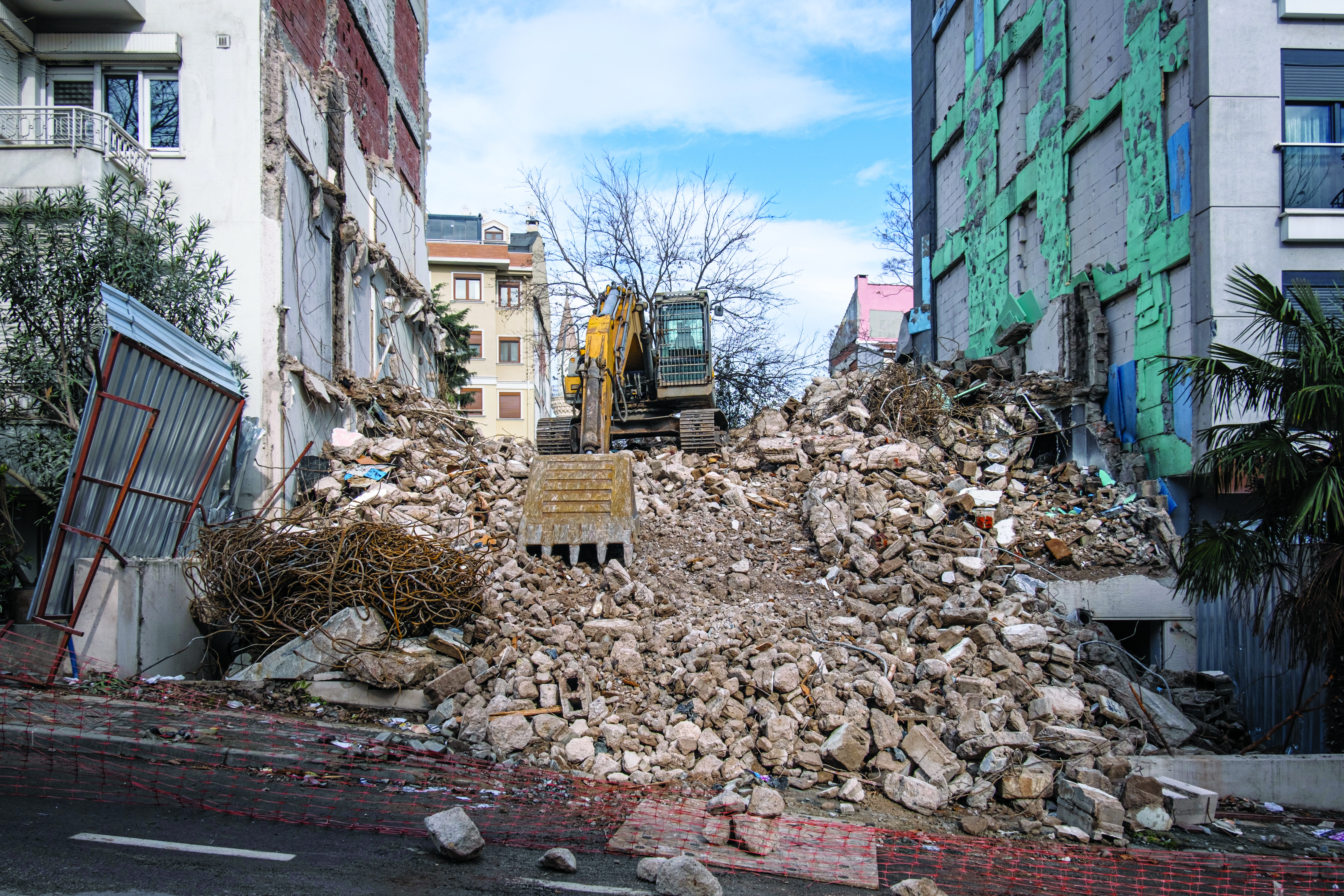
    Many urban areas and critical infrastructure are in regions highly prone to natural disasters such as volcano eruptions, earthquakes, avalanches and landslides, or near man-made systems such as dams and quarries. Monitoring of surface changes and structures is integral to the mitigation of risk and ensuring public safety. Modern remote-monitoring systems allow surface displacements to be monitored without the need to access a location. With these systems, several square kilometers of Earth’s surface can be monitored at once and with high accuracy. The sub-millimeter accuracy of modern remote-monitoring technologies enables accurate measurements to be collected with impressive precision, including in rainy and foggy conditions.

    Remote-monitoring systems are autonomous and can operate for a long time without human intervention. Their real-time feedback makes them suitable for use as early-warning systems. In addition, these monitoring systems can be integrated into a wide range of sub-systems, such as decision support systems that assist decision makers in assessing emergency plans and selecting the best options.

    Using Radar to Measure

    Details of the surface observed by a SAR satellite are encoded in the amplitude and phase of a SAR image. The amplitude component contains information about the surface roughness and terrain slope of the target area, while the phase component contains information about the elevation of the satellite.
    A typical SAR satellite transmits microwave signals toward a target area at an oblique angle and measures the backscattered signal. The intensity of the reflected signal is mainly determined by the roughness and the structure of the target, and the distance between the satellite and the target. This measurement is usually described in terms of the radar cross-section (RCS) parameter, which is obtained by calculating the ratio of the scattered to the intercepted signals as shown in this equation:

    Equation PNT Ca

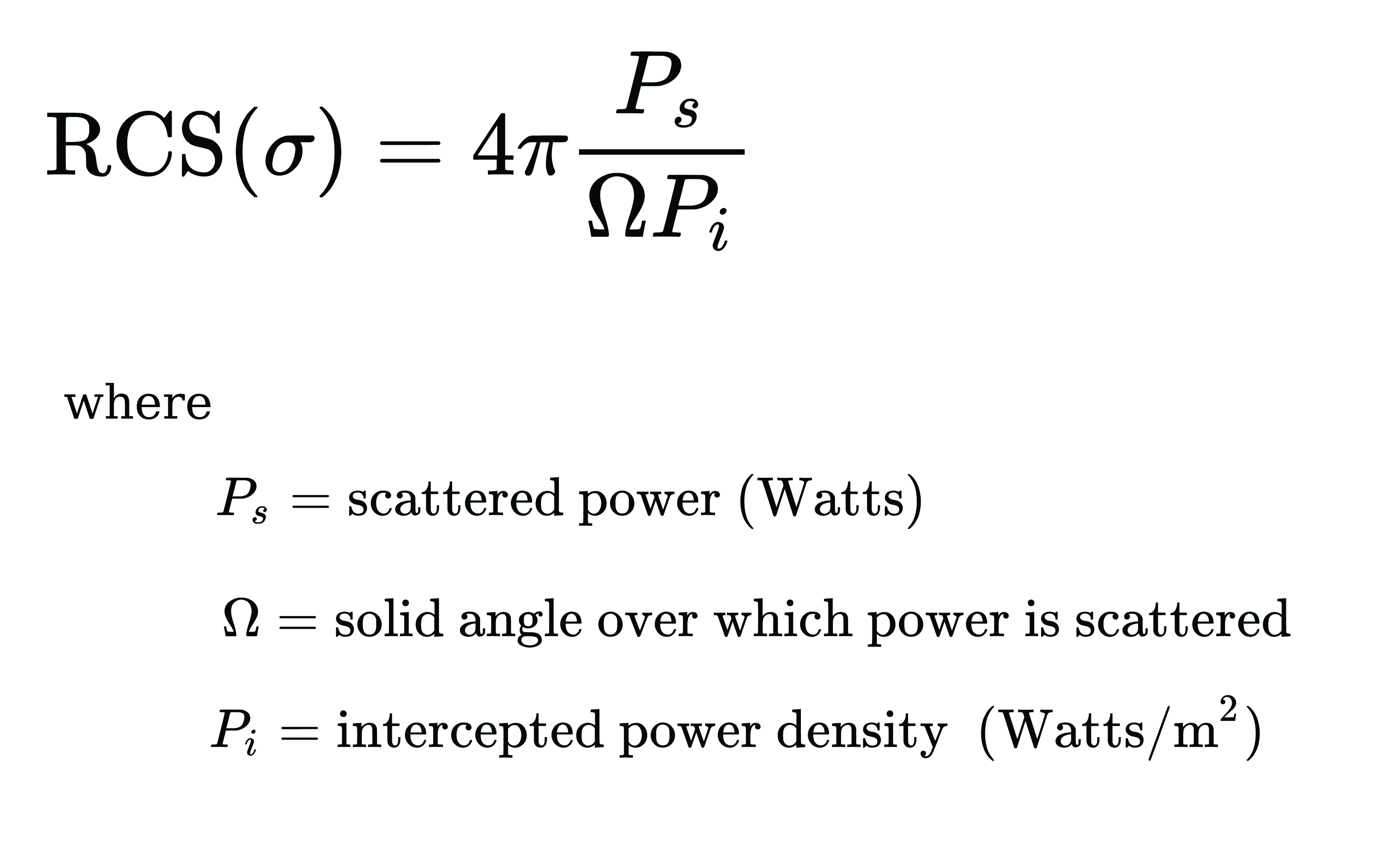
    The RCS parameter is mainly dependent on the surface roughness and the dielectric properties of the target object.
    The interferometric SAR (InSAR) technique allows surface movements to be identified. These observations also can be used to measure and monitor changes associated with volcanic eruptions, tectonic activity and other geophysical processes. To identify crustal changes using this geodetic technique, at least two SAR images are required.

    Figure 1. Phase shift in InSAR observations due to ground movement.
    Figure 1. Phase shift in InSAR observations due to ground movement. (Image: Simon Ndiritu)

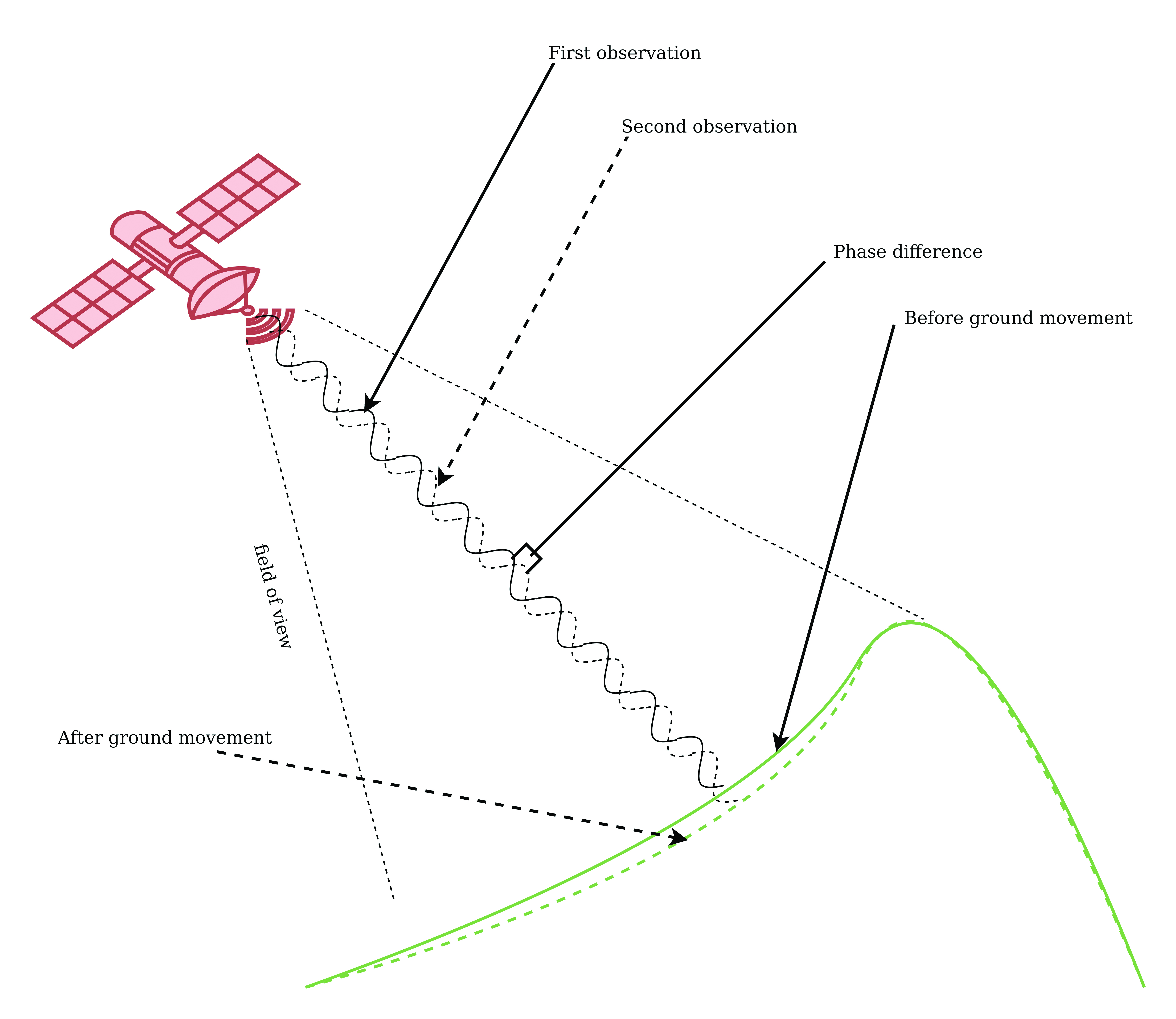
    In differential InSAR, two images of the same location that are recorded at different times are used. If a surface movement has occurred between the first and the second acquisition, a phase shift is observed (Figure 1). The presence of interference fringes on an interferogram is an indicator of a phase shift and these fringes are summed during processing to provide a relative value of the phase change.

    Ground-based SAR (GBSAR) employs the synthetic aperture radar technique to capture high-resolution images of the electromagnetic reflectivity of a target. This remote-sensing system is commonly used for monitoring civil infrastructure, buildings, mines, landslides, glaciers and more. While spaceborne SAR is capable of surveying large areas and records data over long periods of time, usually several weeks or months, GBSAR is suitable for monitoring small areas and has short sampling periods, usually a few minutes. In most surveying applications, the two remote-monitoring techniques are used together in a complementary fashion to enhance the overall performance.

    The all-weather monitoring capability of satellite-based SAR makes it a popular tool for natural disaster management. Since the launch of the first SAR satellite in 1991, this technology has provided many emergency response teams with important insights on manmade and natural hazards. SAR data can be used to study different aspects of long-term behaviors of slow-moving surfaces, which is critical for planning emergency response to natural hazards such as volcanic eruptions, landslides and avalanches. SAR satellites orbit Earth at altitudes of between 500 km and 800 km and operate in the C-band (5 GHz to 6 GHz), X-band (8 GHz to 12 GHz) and L-band (1 GHz to 2 GHz). The temporal resolution of these satellites is mainly determined by their revisit periods.

    Software-Defined Radio Platforms

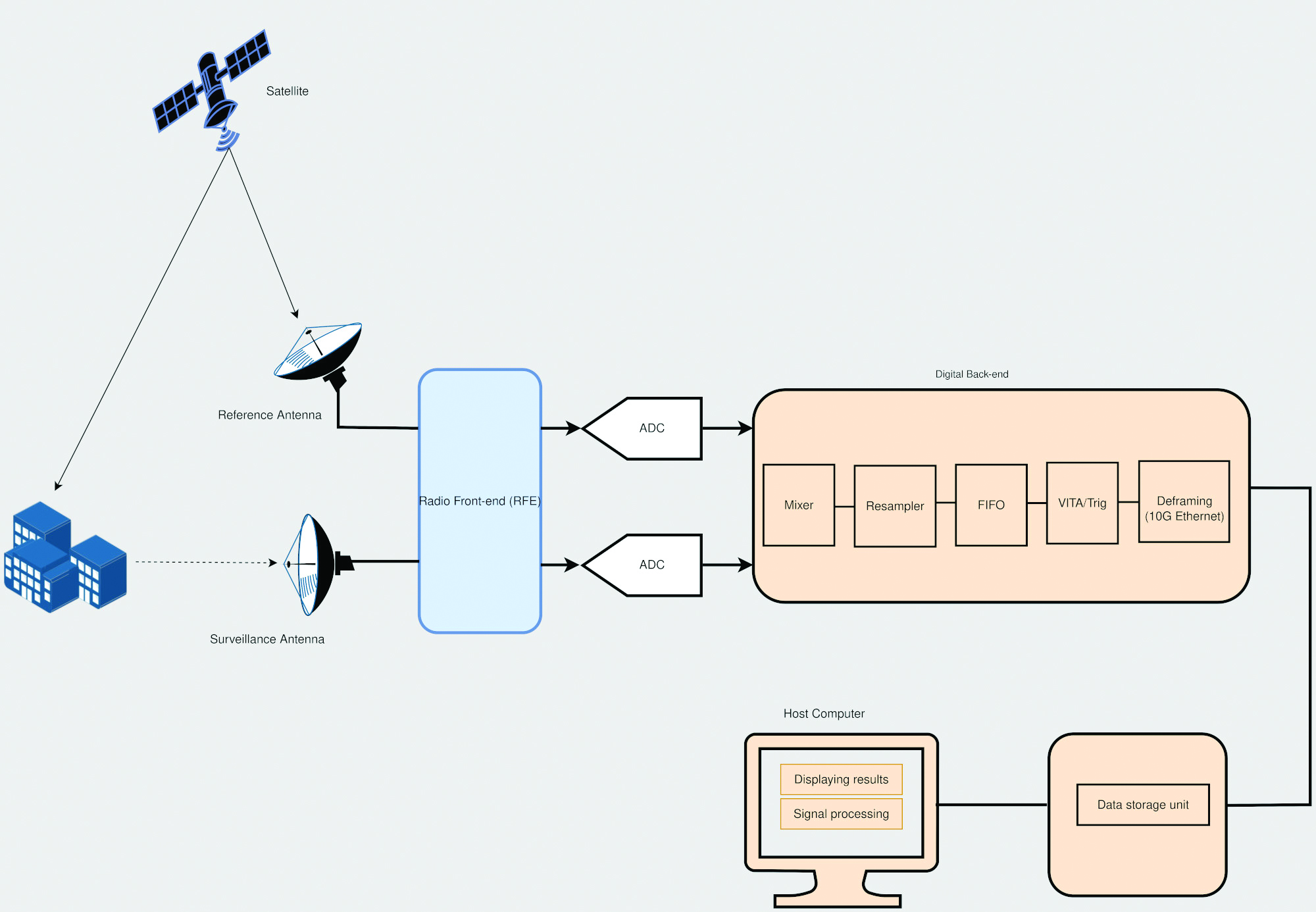
    A typical SDR platform features a radio front end (RFE) and a digital back end, with the RFE performing receive (Rx) and transmit (Tx) functions and offering a wide tuning range, typically 0 GHz to 18 GHz. This range is acceptable for widely used bands in SAR applications, including L-band, C-band and X-band.

    The digital back end of a high-performance SDR system features a field programmable gate array (FPGA). This FPGA offers a variety of digital signal processing (DSP) capabilities, including upconverting, downconverting, modulation and demodulation. In addition, an SDR platform offers multiple transmit and receive channels, making it suitable for implementing multi-in multi-out (MIMO) radar systems.

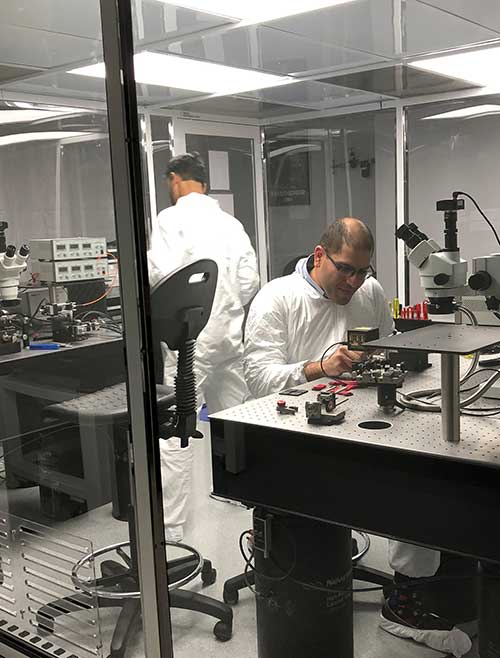
    The architecture of SDR platforms allows them to integrate easily with a wide range of complex systems, such as SAR systems. The reconfigurability of SDRs allows upgrades and updates to be implemented without modifying the existing hardware, and can be designed to meet the size, weight and power (SWaP) requirements of an application. These features make SDRs suitable for implementing custom SAR monitoring solutions in small and large ground stations (Figure 2).

    Figure 2. A simplified diagram of an SDR-based SAR system is shown, which employs a mobile-transmitter fixed-receiver passive bistatic SAR (MF-PB-SAR) architecture. (Image: Simon Ndiritu)
    Figure 2. A simplified diagram of an SDR-based SAR system is shown, which employs a mobile-transmitter fixed-receiver passive bistatic SAR (MF-PB-SAR) architecture. (Image: Simon Ndiritu)

    Integrating SDRs with SAR

    A software-defined radar (SDRadar) is an SDR-based radar system that offers high flexibility and robustness. Compared to conventional radar, SDRadar offers many benefits, including the opportunity to reuse hardware, develop multi-function radar solutions, achieve faster development cycles, and have easier implementation of updates and new algorithms.

    Tests with prototype SDR-based GBSAR systems have revealed the strong potential of SDR-based implementations. The MIMO architecture of an SDR platform allows realization of complex multi-frequency GBSAR systems uniquely suited for measuring displacement and other geophysical characteristics of landforms. SDR-based GBSAR systems can operate in different frequency bands and offer unmatched flexibility when it comes to signal generation and digital signal processing.

    Many prototypes of airborne/satellite SAR systems based on SDR platforms have been implemented and their performance evaluated. Results have shown that they can offer better performance compared to conventional implementations. The use of multiple independent channels by SDR platforms allows the realization of compact and power-efficient multimode SAR systems, while the architecture of an SDR platform allows complex signal processing techniques such as digital beamforming (DBF), null steering and direction of arrival estimation to be implemented on FPGA.

    Benefits of Integrating SDRs with SAR Solutions

    Integrating SDRs into SAR systems provides many benefits. The MIMO architecture of SDR systems provides more channels than are required for SAR functions. The extra channels can be used for other applications such as satellite communications during emergencies. The wide frequency-tuning range of an SDR system allows the realization of a multi-function system with applications using different frequency bands. The reconfigurability of SDR platforms allows them to be repurposed for other applications. In addition, this reconfigurability enhances reusability, scalability and power efficiency. The low-latency FPGAs in high-performance SDR systems allow the realization of ultra-high-speed DSP algorithms for use in image processing and DBF.

    Conclusion

    The reconfigurability and impressive performance features of SDR platforms make them ideal for implementing scalable and flexible SAR monitoring systems for measuring land changes. The wide tuning range and MIMO architecture of SDR devices allows realization of a multi-function and multi-frequency system using a single device. In addition, the reconfigurability of SDR devices allows hardware reuse and low-cost implementation of updates and new algorithms.


    Brendon McHugh is the field application engineer and technical writer at Per Vices. He possesses a degree in theoretical and mathematical physics from the University of Toronto.

    Simon Ndiritu is an independent technical writer for Per Vices with a background in electrical and electronic engineer with a wealth of experience in designing hardware and firmware. He also has a passion for writing.

  • Indoor location could mitigate COVID-19

    Indoor location could mitigate COVID-19

    To prevent the further spread of COVID-19, the world is shifting to a “new normal” in which social distancing is practiced and contact between people is avoided. Due to early evidence suggesting the spread of COVID-19 is much more aggressive indoors than outdoors, many companies have begun efforts to monitor workers’ movements and trace contacts to keep offices and factories from becoming new epicenters of infection.

    The Need to Monitor

    Keeping a safe distance from others and avoiding contact is essential to prevent getting infected with COVID-19. However, there are many situations where avoiding contact with others at indoor locations such as offices and factories is difficult. Hence, there is a growing need for technologies that monitor contact between workers and their movement histories in real time.

    Indoor location information can be obtained using various wireless communication technologies including Wi-Fi, Bluetooth and ultra-wideband (UWB). For example, Bluetooth beacons have been deployed at commercial facilities to enable services that provide location-relevant information to customers with smartphones. The positioning accuracy of Bluetooth, however, is only around 3 to 10 meters and is dependent on infrastructure installation.

    To be useful for contact tracing of infectious diseases, the number of beacons must be increased to achieve an adequate level of accuracy. UWB technology features high positioning accuracy, but deployment in a wide area would require installation of a large number of radio transceivers and repeaters, putting it at a cost disadvantage.

    Solution Based on Geomagnetism

    Given this background, a solution using geomagnetism is attracting attention. TDK has developed VENUE, which displays the real-time locations of people by utilizing geomagnetic sensors found in today’s smartphones. Each indoor location has a geomagnetic signature that can be used to ascertain the position of the phone.

    There are several approaches to indoor positioning, but geomagnetism, tightly coupled with inertial navigation, optimally balances accuracy, reliability and cost of deployment and maintenance.

    “The beauty of geomagnetic positioning is that it works in all large venues whose structures interfere with Earth’s magnetic field, making this an infrastructure-free approach to indoor positioning that is accurate to better than 2 meters,” said Chris Goodall, founder and managing director of Trusted Positioning Inc., a TDK Group Company based in Calgary, Alberta, Canada.


    VENUE provides a position display with even higher accuracy by combining geomagnetic information with information from accelerometers and gyroscopic sensors inside smartphones.


    VENUE requires only the creation of a geomagnetic map that combines an indoor layout map with the geomagnetic data of that particular location acquired through a survey, with no need to install new devices and terminals. This leads to low installation cost. The accuracy of positioning using geomagnetism is better than two meters (6 feet) — sufficient for tracing contact with infected persons. In addition, VENUE provides a position display with even higher accuracy by combining geomagnetic information with information from accelerometers and gyroscopic sensors inside smartphones.

    “People may hold their smartphones while walking or put them in their pockets or bags,” Goodall said. “Since the orientation to the user changes constantly, the movements and pedestrian use cases need to be corrected using inertial sensors. Solving these issues was the greatest challenge for practical applications such as tracking, and took our team many years to create, perfect and protect.”

    Comparison of indoor location information technologies. (Chart: Trusted Positioning)
    Comparison of indoor location information technologies. (Chart: Trusted Positioning)

    Real-World Trial Under Way

    Beginning in August, a contact tracing trial among workers is being conducted at TDK’s headquarters in Nihonbashi, Tokyo, using VENUE. Employees carry smartphones with a special app installed, and their positions and movement histories on the floor are combined with anonymous identification information. If an employee is found to be infected, the data will be analyzed to identify people who had contact with that employee within the preceding two weeks, and measures such as stay-at-home instruction will be taken.

    This solution not only can identify those who were in close contact with the infected person as primary contacts, but also trace those who stayed in areas where the infected person had been shortly before as potential “area contacts.” Analysis that combines location and elapsed time enables more effective contact tracing by improving primary contact tracing indoors and enabling area-based contact tracing over time.

    Ongoing Trial at TDK Headquarters: VENUE displays an individual worker’s tracking data on the dashboard. (Conceptual illustration: Trusted Positioning)
    Ongoing Trial at TDK Headquarters: VENUE displays an individual worker’s tracking data on the dashboard. (Conceptual illustration: Trusted Positioning)
    Ongoing Trial at TDK Headquarters: A worker’s durations of stay and positions can be visualized in the form of a heat map. (Conceptual illustration: Trusted Positioning)
    Ongoing Trial at TDK Headquarters: A worker’s durations of stay and positions can be visualized in the form of a heat map. (Conceptual illustration: Trusted Positioning)

    New Possibilities Opened

    Because VENUE can display the positions and histories of people and objects using not only workers’ smartphones but special tags containing geomagnetic and inertial sensors (under development), it can be deployed for a wide range of applications beyond contact-tracing of infectious diseases. Possible uses include monitoring the flow of employees to improve operational efficiency or tracking positions of equipment to manage their operational statuses. TDK is working with a number of companies on solutions to improve business efficiencies using location information.

    Many offices have introduced open seating, so maintaining a “real-time seating chart” using VENUE is a real advantage so staff can more easily find one another in large office settings, encouraging more collaboration between staff and departments.
    Companies have been using Bluetooth low-energy (BLE) beacons to manage the movement of workers, materials and equipment indoors in warehouses, factories and construction sites. VENUE can reduce the installation and maintenance costs of such systems, especially in large-scale facilities.

    VENUE is also useful for other contact-tracing applications that do not focus on viral transmission, such as human-to-machine, human-to-vehicle and human-to-robot contacts. The future work environment will undoubtedly change with more automation, and the interaction of humans and machines poses safety concerns. VENUE’s designers hope it can improve safety in many types of contact-tracing applications.

    Similar to the expansion of GPS for outdoor positioning applications, indoor positioning technologies will likely grow in our everyday lives. VENUE is one indoor location information solution that enables highly accurate location information to be obtained while keeping infrastructure costs down.

  • Integrating photonic chips for better performance

    Integrating photonic chips for better performance

    KVH photonics engineers test PICs for validation prior to production. (Photo: KVH)
    KVH photonics engineers test PICs for validation prior to production. (Photo: KVH)

    In June, KVH Industries launched the P-1775 inertial measurement unit (IMU), featuring its new PIC Inside photonic integrated chip (PIC) technology.

    After developing and testing the technology for more than three years, the company began incorporating it into existing product lines and has shipped the first units.

    The PIC technology features an integrated planar optical chip that replaces individual fiber-optic components to simplify production while maintaining or improving accuracy and performance.

    The product is designed to deliver 20 times higher accuracy than less expensive micro-electromechanical systems (MEMS) IMUs. It uses modular designs for ease of integration and has outstanding repeatability unit-to-unit, according to the company.

    KVH will add the technology to its inertial sensor product line for use across a broad range of applications, from navigation to stabilization and pointing.

    KVH’s fiber-optic gyros (FOGs) and FOG-based products are particularly well-suited for the large and growing autonomous market, which includes applications on land, sea and air, such as drones, people movers, trucks and mining and construction equipment.

    Moving Components to the Chip

    With PIC technology, KVH’s FOG production process incorporates machine automation for photonics assembly. (Photo: KVH)
    Photo:With PIC technology, KVH’s FOG production process incorporates machine automation for photonics assembly. (Photo: KVH)

    The controls on FOGs have an electronics portion and an optics portion. The latter consists of a light source, a detector, couplers, polarizers, a coil (which performs the sensing), and a piezoelectric device for modulating the light, explained Robert Balog, KVH’s chief technology officer.

    Until now, the company had fabricated all the products for that optical circuit in its Chicago facility, in a process that was labor-intensive and required much process control. For the PIC, “We’ve taken the couplers and the polarizer sections specifically and moved them onto the chip level,” Balog said.

    While KVH manufactures the chip much like any other semiconductor device, rather than passing the light through the fiber KVH is now passing it through wave guides that are contained within that photonics chip, thereby moving the creation of the coupler module into a wafer-level component.

    Mass Production and Better Quality

    KVH produces the chips en masse on a wafer, then singulates and samples them. Once they are qualified and spot-checked, the chips are incorporated into KVH products.
    “This affords us a way to mass produce those components,” Balog said, “and gives us much better quality.”

    Photo: KVH
    Photo: KVH

    Additionally, it produces a much smaller device than before. The company will not reveal any numbers regarding its performance improvement until it produces and distributes more PICs, but “it is already producing better results than the manually produced components.”

    The production process is intimately linked to the overall performance of the sensor. “The tighter your process control, the more reliable you can make the product,” Balog said.

    The new process also improves the device’s field reliability because it contains fewer discreet components. The improved performance specifications on each individual FOG improve the overall performance of the IMU or the inertial navigation system (INS) because the bias is more stable and repeatable.

    The Future

    What is in the technology’s future?

    “The next step is integrating the light source and the detector and potentially a modulator into that chip as well,” Balog said. “So, our ultimate technology road map is to continue condensing what would have been discrete components in traditional gyros all within that chip. As this technology progresses, it will get smaller, tighter, and better. Then you will see big leaps in performance.”