Tag: real-time network

  • Review benefits of GNSS rover accuracy

    Review benefits of GNSS rover accuracy

    Douglas County Public Works needed a GNSS rover to support its UAS operations. The pay-as-you-go option was appealing as they only needed high-precision a few times per month. (Image: Jason Schilling)
    Douglas County Public Works needed a GNSS rover to support its UAS operations. The pay-as-you-go option was appealing as they only needed high-precision a few times per month. (Image: Jason Schilling)

    This is part II of our III part feature story. Check out part I, Minnesota company develops new system for mapping underground utilities and part III, Robotic total stations add scanning capabilities.


    High precision GNSS rovers play a vital role in a broad variety of field surveying and mapping applications. Different users have different value propositions in mind when choosing field hardware and software: expected precision, sources of corrections, configurations for specific workflows, and, of course, cost. Weighing these many considerations, GNSS manufacturers have come up with portfolios of multiple models to fill these varied needs.

    That said, GNSS manufacturer Bad Elf took a different approach when it designed its flagship rover, the Bad Elf Flex. The Flex is designed to meet the cost-precision-workflow needs of everyone, from asset mappers to surveyors. (Hence the name “Flex.”) To inform the design of the Flex, Bad Elf listened to field users who wished for a scalable solution in a single rover, rather than having to buy multiple different models, and without breaking the bank.

    Options for the Infrequent User

    “I had one of the little Bad Elf GNSS surveyor handhelds for many years,” said Jason Schilling, wildlife biologist with Douglas County Public Utility District in central Washington State. “That worked great for rough mapping, between a foot and a meter of precision, and I could connect it via Bluetooth to mapping software on my mobile.”

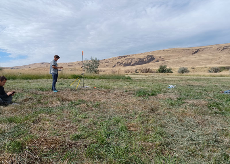
    But this all changed when Schilling began an unmanned aerial system (UAS) program for the utility several years ago.

    “I really needed survey-level precision for ground control points to geolocate the images from the UAS,” said Schilling.

    He was aware of the high cost of centimeter-precision-capable surveying rovers and it was too big of an investment, considering that he only did UAS mapping a few times a month. As an existing Bad Elf customer on the company mailing list, Schilling learned about the new Flex rover, which offered multiple options, and he found one that seemed quite enticing for the needs of his utility.

    Schilling purchased a Flex Standard bundle at a low base price, about $3,000, with the pay-as-you-go plan for high precision. In the standard configuration, the Flex is capable of autonomous positioning (1–5 m), and mapping grade (sub-meter precisions) via free satellite-based augmentation services (SBAS), such as WAAS. But when the user activates a pre-purchased “token,” the full centimeter-precision capability, using external corrections, is enabled.

    “On the day of a UAS survey, we turn it on, activate a token from our account, and then we have 24 hours of high precision,” Schilling said. “It costs us $25 per day.”

    For two to three UAS surveys a month, this works out to far less over many years than the cost of buying a typical surveying rover.

    Correction Sources

    For real-time kinematic (RTK) corrections, Schilling connects via NTRIP to the statewide cooperative real-time network (RTN); sometimes in a network RTK mode (such as VRS) or single-base RTK to a nearby reference station on the same network. The Flex accommodates NTRIP connections to RTN or IP-enabled reference stations, but Bad Elf has added even more flexibility for corrections.

    In some scenarios there is no access to an RTN or no cell service (needed for NTRIP access). One option in these cases is to add a second Flex, set it up as an RTK base, and connect the base and rover via radios that Bad Elf offers.

    Bad Elf has added other options for corrections: the Bad Elf RTK service taps into a nationwide real-time network operated by Point One Navigation. This is accessible via NTRIP in the same manner as regional, state or local RTN, and is offered for a monthly fee. In addition, for situations where there is no RTN or cell service, a global precise point positioning (PPP) service (Atlas) can be enabled on the Flex.

    PPP differs from RTK/RTN in that it does not need the dense arrays of reference stations, or cell service to access. Instead, PPP derives very precise clock and orbit data from a global array of tracking stations and delivers this to the Flex via geostationary satellites. After a short convergence time, PPP from the Atlas service will yield 5 –10 cm precision over most of the globe.

    The Full Boat

    full configuration. Brian Cortese works for the City of Ellensburg, where he uses the FLEX Extreme Bundle for multiple field applications. (Image: Brian Cortese)
    Full Configuration. Brian Cortese works for the City of Ellensburg, where he uses the FLEX Extreme Bundle for multiple field applications. (Image: Brian Cortese)

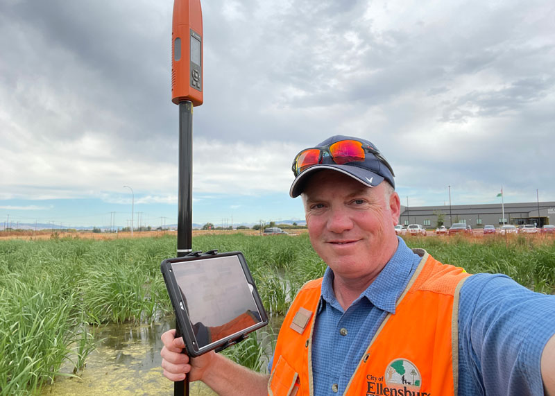
    The City of Ellensburg, a college town and farming community in central Washington State, chose the Flex Extreme bundle for about $6,000 — the “full boat” configuration. The Extreme bundle enables all the add-on services all the time, eliminating the need for tokens. In their case, the frequency of use made the higher initial investment worthwhile.

    “We have big plans for our rovers,” said Brian Cortese, Engineering Tech/Inspector for the City of Ellensburg Public Works & Utilities.

    Ellensburg is a vibrant town that is attracting a lot of new development and it is being proactive in surveying and mapping assets as they are added or replaced.

    “We’re recording manholes and valves, sewer systems, storm water systems, irrigation, hydrants — everything that gets built in the city gets as-built surveyed,” Cortese said. “Precise, real-time positioning, it’s been a benefit to us already. We can go out before they work on the subgrade for new developments and take measurements, and then when they finish the subgrade and pave it, we can go back and locate those exact positions.”

    Ellensburg uses corrections from the statewide cooperative RTN. In fact, one of the RTN reference stations —also part of the NOAA National CORS Network — is right in the center of town atop the science building of Central Washington University. While the city does a wide variety of surveying and mapping, with the Flex and RTN corrections surveyors get the same centimeter-precision for everything they measure in the field.

    “We’ve done design projects with it,” Cortese said. “For instance, we recently took measurements in an area of downtown for a proposal by recording positions and elevations to develop a new park and entertainment area for the community. We are also marking Americans with Disabilities Act (ADA) ramps to meet federal specs out in the field — it’s been really handy for so many things.”

    Survey-Grade Rover

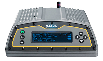
    To serve the full range of precision needs, the Flex had to be designed as a survey-grade rover. It has a full-constellation GNSS and RTK engine: GPS, GLONASS, Galileo, BeiDou, and support for other regional constellations. With more satellites in view, it can perform in sky-view-challenged locations, such as around buildings and under tree canopy.

    “Ellensburg is on the Tree City, USA list; our streets are very well lined with a variety of trees, which is also where a lot of our utilities are and development is going on,” Cortese said. “We have been able to get good precisions in and around those trees. Actually, someone on our staff is taking an inventory of the trees with the Flex and loading the data directly into ArcGIS.”

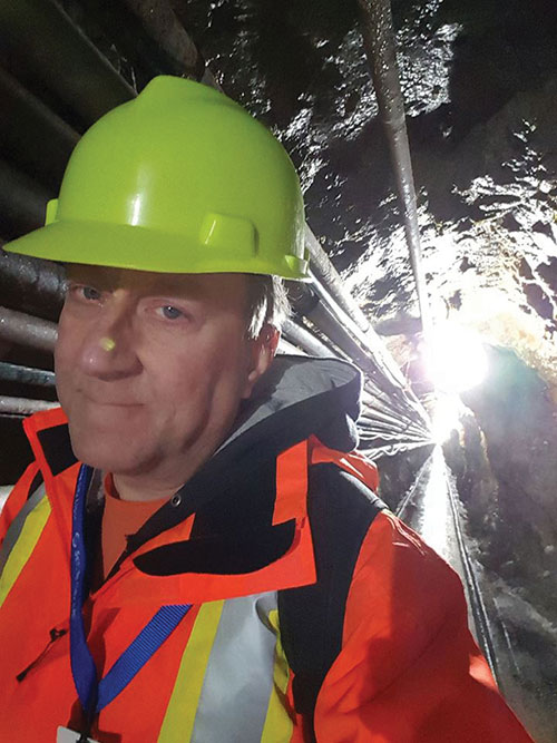
    Even in the more rural areas of Grant County that enjoy a lot of open sky, Schilling said, some areas planned for mapping are along upper tributaries and in the hills with a lot of tree coverage. He said the Flex has performed well in those areas.

    Choices

    The Flex offers these options and combinations:

    • Flex Extreme. Full survey-grade rover that can use a variety of correction types.
    • Base-Rover RTK. Two Flex Extreme units connected via radio.
    • External RTN/RTK corrections via NTRIP.
    • Bad Elf RTK Service. Single-tap access to a nationwide RTK corrections service.
    • PPP service. Atlas PPP corrections via L-band geostationary satellites.
    • Flex Standard. Pay-as-you-go high-precision-enabled service using tokens.
    • Static Logging. Observation file logging for post-processing (supported by Flex Extreme).
    • Compatibility with multiple field-mapping software applications.

    While many modern GNSS rover systems support one or more options similar to those listed above, Bad Elf’s Flex supports all of them, making it capable of a wide variety of applications.

  • NGS Beta OPUS released, accepting RTK and post-processed data

    NGS Beta OPUS released, accepting RTK and post-processed data

    On Sept. 16, the National Geodetic Survey (NGS) released the latest beta version of OPUS, called Beta OPUS Projects 5.0.  This version of OPUS now accepts real-time kinematic data and post-processed GNSS vectors from vendor software. See the box titled “Beta OPUS Projects 5.0 Webpage” on the website.

    As stated in the announcement, NGS has developed a file format for submitted real-time kinematic (RTK) data and post-processed GNSS vectors from vendor software to NGS. It is denoted as GNSS Vector Exchange Format (GVX).  This format enables NGS to incorporate the data into its GNSS processing routines.

    This is similar to the original Receiver Independent Exchange Format (RINEX) developed for making post-processing more efficient when combining GNSS data from manufacturers outputting raw GPS data in varying file formats. In my opinion, this is a significant improvement to NGS’s OPUS web utility.

    Beta OPUS Projects 5.0 Webpage

    Image: NGS website
    Image: NGS website

    Users can obtain background information about the GVX file format by clicking the link GVX file format. More detailed information about the GVX format can be obtained by clicking on the Documentation link.

    GNSS Vector Exchange File Format Webpage

    Image: NGS website
    Image: NGS website

    Basically, GVX is a standardized format for exchanging GNSS vectors derived from GNSS survey data using any manufacturer hardware and software results (see the box titled “Excerpt from Documentation of GVX”).  NGS designed the format so that it included all of the necessary data (including metadata) of a GNSS vector for incorporation into a survey network for performing a least-squares adjustment.

    Excerpt from Documentation of GVX

    (Link to PDF of GVX Documentation)

    To this end, this document proposes a new standardized file format known as the GNSS Vector Exchange Format (GVX). GVX aims to provide a standard format for exchanging GNSS vectors derived from varying GNSS survey methods and manufacturer hardware. The file format includes all of the necessary data of a GNSS vector for inclusion in a survey network for least squares adjustment, as well as metadata which describes the vector. The format is meant for any type of GNSS vector, whether it was derived in real-time or from baseline post-processing. GVX has been written in extensible markup language (XML). XML was chosen because it was designed to carry and store data in plain text format, it is easy to expand and/or upgrade to new operating systems, and it can be read by both humans and machines.

    A sample GVX file can be obtained by clicking on the link titled “Example of GVX file, project day 066, day 052, day 053, day 054.” As NGS states in the documentation, the output can be read both by humans and machines. What’s important is that it can be read by machines so the information can be incorporated into software programs. GNSS vendors have all the information they need to generate the output file to enable users to import the data into OPUS Project 5.0. Users will have to contact their software providers to determine whether their software routines generate the GVX output files.

    Example of GVX file, project day 066

    Image: NGS website
    Image: NGS website

    As I previously mentioned, this new option in OPUS Projects 5.0 is a significant improvement because many surveyors use RTK networks to obtain coordinates of marks. It will also facilitate the occupation of benchmarks with GNSS equipment to support the NGS 2022 Transformation tool. North Carolina, my home state, has a real-time network (RTN) that includes 96 GNSS CORS. (See the box titled “NC GNSS CORS and Real-Time Network.”) Currently, the North Carolina GNSS CORS and RTN has 4584 RTN service subscriptions.

    NC GNSS CORS and Real-Time Network

    Image: North Carolina Geodetic Survey Website
    Image: North Carolina Geodetic Survey Website

    I could not find a current list of public RTK networks in the United States, but I did locate a Jan. 7, 2014, GPS World article by Eric Gakstatter that provided a list of public RTK base stations in the country. It’s not up-to-date, but it highlights that, more than seven years ago, more than half of the U.S. states  had some kind of public RTK network. I would like to update the table, so I’d appreciate receiving information on the status of any public RTK network. Please feel free to send me an email at [email protected].

    List of Public RTK Base Stations in 2014

    Based on GPS World 2014 Article by Eric Gakstatter

    Note: States not listed did not have a public RTK network.

    State

    Status of Public Network

    Alabama Alabama Department of Transportation. Leica network.
    Alaska Two PBO RTK bases. One in Fairbanks and one in Palmer. Otherwise, no public service.
    Arizona Arizona State Cartographer’s Office. Leica network. Plate Boundary Observatory (single baseline).
    California California Real Time Network (CRTN) (single baseline).  Plate Boundary Observatory. Single baseline.
    Colorado Mesa County (Trimble network) and Plate Boundary Observatory (single baseline).
    Florida Florida Department of Transportation. Leica network.
    Idaho Plate Boundary Observatory (single baseline).
    Indiana Indiana Department of Transportation. Leica network.
    Iowa Iowa Department of Transportation. Leica network.
    Kentucky Kentucky Transportation Cabinet. Trimble network.
    Louisiana Louisiana State University. Trimble network.
    Maine Maine Department of Transportation. Trimble network.
    Massachusetts Massachusetts Department of Transportation. Leica network.
    Michigan Michigan Department of Transportation. Leica network.
    Minnesota Department of Transportation. Trimble network.
    Mississippi University of Southern Mississippi. Trimble network.
    Missouri Missouri Department of Transportation. Trimble network.
    Montana Plate Boundary Observatory (single baseline).
    Nevada Washoe County. Trimble network. Las Vegas Valley Water District. Leica network. Plate Boundary Observatory (single baseline).
    New Mexico Plate Boundary Observatory (single baseline).
    New York New York Department of Transportation. Leica network.
    North Carolina N.C. Department of Environment and Natural Resources. Trimble network. $500 one-time sign-up fee.
    Ohio Ohio Department of Transportation. Trimble network.
    Oregon Oregon Department of Transportation. Leica network. Plate Boundary Observatory (single baseline).
    South Carolina South Carolina Geodetic Survey. Public but charges a usage fee. Trimble network.
    Tennessee Tennessee Department of Transportation. Public but charges a usage fee. Topcon network.
    Texas Texas Department of Transportation. Public but only available to TxDOT employees and TxDOT contractors. Trimble network.
    Utah Utah Automated Geographic Reference Center.  Public but charges a usage fee. Trimble network. Plate Boundary Observatory (single baseline).
    Vermont Vermont Geodetic Survey. Trimble network.
    Washington Washington State Reference Network (Seattle Public Utilities). Trimble network. Public but charges a usage fee. Pierce County (Leica Network). Plate Boundary Observatory (single baseline).
    West Virginia West Virginia Department of Transportation. Trimble network.
    Wisconsin Wisconsin Department of Transportation. Trimble network.
    Wyoming Plate Boundary Observatory (single baseline).

    Why do I believe that this new option in OPUS Projects 5.0 is so important? Because it facilitates the incorporation of accurate GNSS-derived ellipsoid and orthometric heights into the National Spatial Reference System (NSRS).  With the development of improved algorithms, the results of coordinates computed using GNSS CORS/RTNs are more accurate today than ever before. During the last decade, there have been many studies analyzing GNSS data to estimate the accuracy values of coordinates from RTN data.

    A study titled “Accuracy of GNSS Observations from Three Real-Time Networks in Maryland, USA” by Daniel Gillins, Jacob Heck, Galen Scott, Kevin Jordan and Ryan Hippenstiel presented at FIG Working Week 2019 in Hanoi, Vietnam, April 22–26, 2019, provided a comparative evaluation on the accuracy of three independent RTNs constructed with differing hardware and software. Their study was based on 486, 5-minute duration GPS + GLONASS network RTK (NRTK) observations. The results indicated that repeat NRTK vectors could be combined to meet 1 cm horizontally and 2 cm vertically (ellipsoid height) accuracies at 95%. confidence.  See the box below.  It should be noted that the repeat observations should be observed at different times of the day (for instance, separated by > 2–3 hours), as well as, in my opinion, if possible at least more than two different days.

    Conclusions from Daniel Gillins, et al. 2019 FIG Paper

    A total of 486, 5-min duration, GPS+GLONASS NRTK observations were collected on nine bench marks distributed over a 4,000 square km area with rovers connected to three different RTNs in Maryland. Each RTN was developed with equipment and software from a different manufacturer, yet all three RTNs performed similarly in terms of accuracy. When differenced with coordinates from a static GNSS survey campaign, the horizontal and vertical RMSE of the NRTK-derived coordinates was 2.3 cm horizontally and 4.5 cm vertically at 95% confidence. Repetitive NRTK vectors on each baseline differed between ± 2.4 cm horizontally and ± 3.4 cm vertically at 95% confidence. As a final accuracy evaluation, hybrid survey networks consisting of repeat NRTK vectors and baseline solutions from post-processing static GPS data collected at RTN base stations and CORSs were adjusted by least squares. Prior to adjustment, the VCV matrices of the vectors were scaled by variance-component estimation. Adjustment of hybrid survey networks with four repeat NRTK vectors per bench mark produced network accuracies at 95% confidence for the adjusted coordinates at all bench marks less than 1 cm horizontally and 2 cm vertically (ellipsoid height). In addition to the benefits of using efficient and accurate NRTK vectors, the hybrid survey network approach makes use of redundant vectors for checking data and avoiding blunders. The approach also provides traceability because the NRTK vectors are tied to an RTN base station which is tied to CORS. Finally, these networks ensure the survey is referenced to the published coordinates of the CORSs which are held as constraints in the adjustment.

    Lastly, I would like to remind users that only three months remain until the December 31, 2021, cutoff to submit GPS on Benchmarks data that NGS can guarantee will be analyzed to compute the initial set of 2020.0 Reference Epoch Coordinates (RECs) that will be released with the Modernized NSRS. This initial set of RECs is currently the only set that NGS can guarantee will be used to build the 2022 Transformation Tool.  Once the transformation model is finalized, the NAVD 88 – NAPGD 2022 transformation values will be locked in and will not be updated as additional sets of RECs are computed.  If you have questions or concerns about this cut-off date, please contact your NGS Regional Geodetic Advisor, or drop NGS a line at [email protected].

    Beta OPUS Project 5.0 is a web-based tool that makes it easier to submit data to NGS.  I would encourage NSRS users to occupy as many benchmarks with GNSS equipment and submit the data to NGS before the Dec. 31 deadline.  Not only will these data help in improving the transformation model, but the marks will be included in the first computation of Reference Epoch Coordinates (RECs).  You can obtain information about Reference Epoch Coordinates in NGS’s NOAA Technical Report NOS NGS 67 publication titled “Blueprint for the Modernized NSRS, Part 3: Working in the Modernized NSRS.” A future column will address the different types of coordinates that will be distributed by NGS with the modernized NSRS.

  • The hazards of mixing RTK bases

    The hazards of mixing RTK bases

    Single-base RTK is an excellent choice for many uses but mixing different baseline lengths can yield inconsistent results

    By Gavin Schrock, PLS

    Gavin Schrock, PLS
    Gavin Schrock, PLS

    The surveying lead for a construction firm started getting calls from his crews — suddenly they were not checking in to existing control with the accuracy required. This presented a conundrum and an immediate resolution was needed to stay on schedule. What had changed? A nearby permanent base, part of the regional real-time GNSS network (RTN), had suddenly gone dark, and when the crews switched to other bases, they got the inconsistent results. Time to call the RTN. (See a primer on RTN.)

    I have been operating a regional cooperative RTN for 19 years, and I get these kinds of support calls regularly, but typically only from users of the single-base mountpoints. Most RTN provide, via NTRIP casters, both network RTK (NRTK) solutions — such as master-auxiliary, VRS and FKP — and single-base solutions for each base. The base they had been using was down while the roof of the city building on which it is mounted was undergoing some maintenance.

    The construction firm, halfway through a multi-year transportation project, had used the base when they established project control, and for layout and as-built tasks. Using the base, which was slightly more than 4 km from the site, the crews were used to seeing check-in results of 0.3′ (9 mm) or better (horizontal). When they switched to different bases, 23 km and 25 km distant, the results were now inconsistent, and in many instances, double.

    This was an easy fix. We met on site and checked results using the network solution; it closely matched the results they were seeing from the original base. Until the original base was restored, this would meet their needs.

    It made a lot of sense to use the nearby base, as setting a temporary project base on the congested and sky-view challenged site was impractical. Furthermore, the baseline length of 4 km yields excellent results. Single-base RTK is a powerful tool, and a default for many construction projects, provided that:

    • the base has an unobstructed view of the sky
    • the base is free of nearby multi-path hazards
    • the base receiver and the antenna are of the same or better quality as the rovers
    • the base receiver and the antenna support the constellations and the signals desired.

    In many ways, it is hard to beat single-base RTK. For instance, if you set up a base right on the site, say less than a kilometer away, this should yield the best results possible for RTK, and can be better than network RTK.

    However, there are challenges. Single-base, typically “iono-free” solutions common in today’s rovers, degrades over the baseline length. The rule of thumb for many is that the degradation becomes noticeable when baseline lengths exceed 10 km. It is not uncommon for rovers to fix at much longer baseline lengths; 20 km, 30 km, 50 km or more — but results will likely vary from hour to hour or day to day. Changes in ionospheric and tropospheric conditions can bring inconsistencies, particularly over longer baseline lengths.

    Network RTK may not beat single-base over very short baselines, but as it uses 5 to 15 bases (depending on the implementation) it can better model in the varied conditions. It can provide great consistency and repeatability, even if an individual base is unavailable, as was the case for this conduction site. There are strengths and weaknesses for both. NRTK brings consistency over a wide area, you do not have to set up (and guard) your own base, and the geodetic values are solved.

    If you can have an on-site base, you can under certain conditions see a gain in results. This is especially important for certain applications, such as machine control and precision agriculture, for which tight year-to-year and row-to-row repeatability is key. However, if you may need to use another base at some point, you may be better off starting with NRTK, if it yields the results you seek.


    Gavin Schrock is a practicing surveyor, technology writer, editor of xyHt Magazine and operator of a cooperative GNSS network.

  • The expanded role of positioning through advancements in GNSS

    The expanded role of positioning through advancements in GNSS

    Auto Mining: A driverless Cat 793F CMD truck leaves an iron ore pit. (Photo: Caterpillar)
    Auto Mining: A driverless Cat 793F CMD truck leaves an iron ore pit. (Photo: Caterpillar)

    Individuals who use GNSS today may not know the significant advancements that have been accomplished over the past 30 years to obtain accurate GNSS-derived coordinates, especially GNSS-derived orthometric heights.

    Thirty years ago, there were two limiting factors for estimating GNSS-derived heights — estimation of accurate ellipsoid heights in a timely manner and the availability of an accurate geoid model. The geoid model was only good to the decimeter level, between two stations relatively close together. A significant improvement of the measurement of the Earth’s gravity field (such as from the GRACE mission) and digital elevation data (from the Space Shuttle Radar Topography Mission) facilitated the creation of more accurate geoid models. Geoid models went from decimeter values to centimeter, and then sub-centimeter values between closely spaced marks.

    A new national network

    During the past three decades, the U.S. National Geodetic Survey (NGS) has developed a national network of Continuously Operating Reference Stations (CORS). These CORS, along with the states’ real-time networks (RTNs), have provided the ability to compute accurate GNSS-derived coordinates in an efficient and effective manner. The modeling of antenna phase patterns was a critical development for combining different types of antennas.

    Today’s GNSS processing software is basically a “hands-off black-box” system. But 30 years ago, the analyst had to identify cycle slips and ensure that all unknown cycle ambiguities of the carrier-phase data (integers) were determined correctly. It was a time-consuming task, and analysts needed to understand the data. So many things can go wrong when someone relies on an answer from a black box. That said, federal agencies such as NGS and GNSS software companies have produced hands-off software that provides statistics and warning messages, as well as guidelines for ensuring results are consistent and accurate.

    The advancements in estimating GNSS-derived coordinates (including orthometric heights) have changed the way many industries do business. Farmers use it to drive their tractors and combines, mining companies control driverless vehicles, construction companies use automated machine guidance to build roads, and, of course, it has improved how individuals navigate from one location to the next.

    Hands-off farming and mining

    Thirty years ago, few farmers thought they would be able to sit in their cab and let their combine harvester drive itself. Geodesist, surveyors, and engineers had a vision of using GNSS to automate the use of farming and construction equipment, which became a reality.

    What will it be like in another 30 years? Will it be routine for individuals to program their car for a destination, and then sit back and read a book?

    Positioning with GNSS will be critical for the safety factor of driverless vehicles and the use of drones for delivery. Geodesists, surveyors and engineers, once again, need to lead the way to meet the positioning requirements of the future.

  • Trimble Pivot, Alloy GNSS receiver now support BDS-3 signals

    Trimble Pivot, Alloy GNSS receiver now support BDS-3 signals

    Photo: Trimble
    Photo: Trimble

    Trimble has added capabilities to its real-time network (RTN) portfolio, including the Trimble Pivot Platform and the Trimble Alloy GNSS reference receiver.

    The new capabilities will enable operators to continue to meet the ongoing demand from surveyors, mapping professionals and precision farmers for accurate, reliable corrections derived from real-time networks.

    The announcement was made at Intergeo 2019, the world’s largest conference on geodesy, geoinformatics and land management, taking place Sept. 17-19 in Stuttgart, Germany.

    Boosting RTN performance. A well-established network software, the Pivot Platform manages and controls small, mid-size and countrywide GNSS networks. By applying sophisticated atmospheric models to reduce systematic errors, highly accurate GNSS corrections are generated and made available for a wide range of field applications.

    BDS-3 now supported

    Both Pivot and Alloy now access BeiDou Generation III (BDS-3) signals.
    Trimble Pivot version 4.3 has been enhanced to track and store BDS-3 — RTN operators worldwide now have the ability to provide their customers with additional satellite signals to offer even more robust and reliable positioning for their applications. This update also includes a simplified Chinese user interface, providing easy-to-use software operations for Chinese RTN operators.

    Released in 2018, the Alloy GNSS reference receiver was designed with the processing power needed to deliver high-quality data from multiple GNSS constellations. Alloy version 5.42 firmware tracks all available and planned GPS Block IIIA L1C and BDS-3 signals, empowering operators with a full GNSS constellation dataset.

    “These updates keep the Trimble Pivot Platform and Alloy on a future driven path,” said Mark Richter, strategic marketing director, Real-Time Networks and Services portfolio for Trimble’s Advanced Positioning Division. “Our focus is to continue to deliver enhancements influenced by market demands and advancements in technology, which deliver next-generation RTN hardware and software to our customers.”

    The Trimble Pivot Platform and Trimble Alloy GNSS reference receiver updates work in conjunction to provide quality GNSS corrections to network operators and end users.

    Trimble real-time networks and services

    Trimble RTN networks and services are a widely used GNSS infrastructure solution. Spanning a variety of applications and industries worldwide, Trimble’s hardware is specifically developed for RTN real-world environments while the software integrates seamlessly into the RTN solution for exceptional real-time performance.

    The flexibility of Trimble’s solution enables users to collect, manage and analyze complex information faster and easier, improving productivity and efficiency.

  • Accuracy, precision and boundary retracement in surveying

    Accuracy, precision and boundary retracement in surveying

    Technology has improved the scientific community’s ability to measure in many ways that our ancestors would have trouble believing. From obtaining measurements across galaxies down to the tiniest of atom splitting, our ability to measure is exceedingly robust. The land surveying profession has benefitted from this ongoing technological revolution in many ways (GPS World March 2017) and has advanced our work in many new directions never thought possible. Substantial increases in precision through these advancements allows the land surveyor to perform various tasks, including topographic surveys, construction layout and volumetric surveys with increased confidence.

    Graphic: https://sites.google.com/a/apaches.k12.in.us/mr-evans-science-website/home

    Accuracy and precision are two factors that go into our measurement procedures. While accuracy and precision are considered to be the same thing by a large portion of the population, it couldn’t be more from the truth. Accuracy is defined on how well a measurement or reading is in relation to a known value or benchmark. Precision, on the other hand, is how closely a measurement is repeated yet has no relation to any given value or benchmark.

    The introduction of GNSS technology along with total stations with locking electronic distance measuring (EDM) mechanisms in the 1980’s brought more precision into the hands of the surveyor. These innovations reduced the amount of human error in our measuring procedures when used in an appropriate manner as well as allowing greater distances to be covered. The implementation of various real-time networks (RTN) on several continents also continues to increase our range of high-precision location and measurements worldwide. However, as we develop our next generation of surveyors through educational programs and apprenticeships, we are making a terrible mistake in replacing many fundamental land surveying principles and legal precedents with more emphasis on precision and less on legal accuracy based upon precedents.

    Surveyors and the role of measurement

    In ancient civilization, the primary role of the land surveyor was to help establish and maintain property boundaries. Measurement devices included knotted rope, the Gunter chain and the compass, all used is varying manners and precisions. Paramount to the surveyor’s effort was the establish of monuments at corner points of the tracts they were measuring. These points were held as the ultimate dividing point and superior to associated measurements and secondary tie points. This simple guide for all surveyors has been a core principle of property owner’s rights and upholding those rights in the name of the law. By placing of monuments, the landowner has relied on the surveyor to physically define the property being established and conveyed.

    Let’s ask Washington, Jefferson and Lincoln…

    For example, in early days of the United States during the late 1700’s/early 1800’s, once an original survey was completed, notes of each survey were preserved by various means. Most governmental surveys of the early 1800’s were transcribed onto large township sheets in order to perpetuate and preserve the work performed by the Land Office surveyors. The establishment of states and local governments brought forward land and records offices in which these government patent lands were further subdivided for conveyance to settlers of the new lands. In each of these cases, corners of various types were set to distinguish boundaries between property ownership. Wooden posts, rock mounds, and other materials were used to physically mark the locations of the corners, with notes, documentation and deeds for conveyance coming after the determination of the property. Regardless of any variation from the notes/plats/deed descriptions, property rights were held to the physical locations of the markers set during the course of the survey.

    The American dream of land ownership

    As more people moved westward and parcel subdivisions became more prevalent, planned developments began to be based upon pre-calculated figures. Before calculators and computers, the surveyor would determine the location of new parcel corners by hand derived calculations (usually in the field) and use a transit and chain to stake each parcel corner. Notes were carefully kept during the lot creation process and transferred to a final plat for filing at the county recorder’s office. These plats were typically post-survey with the detailed notes being drawn on the plat with specific dimensions to all points set.

    As plane geometry and coordinate systems caught on (GPS World November 2016), the movement toward pre-calculated subdivisions became more common. Couple this method of calculation with increased capability of high precision theodolites and the World War 2 postwar boom, the economy and environment was ready for more time efficient surveys. Now large parent parcels were being subdivided on paper before any additional surveying was performed to establish the new lotting configuration. Surveyors began to stake parcel corners by means other than “running the lines”, i.e. physically occupying the outer boundary and setting internal points for new parcels. Add to this environment of “faster” surveying the invention of the EDM, digital total station, computer programming and analysis along with GNSS, and now we have a recipe for the most precise and accurate surveying ever performed. Or do we?

    These are not your father’s (or grandfather’s) survey methods anymore

    Regarding topographic, volumetric, bathymetric and aerial surveys, I would agree that technology has advanced our profession to greater heights. These tasks have benefited greatly by increased data collection, remote location and sensing and computing power. The surveyor’s ability to provide an extremely detailed set of data for varying surfaces and site conditions is at an all-time high with more technology continually being developed. But how has technology affected our primary role of boundary line expert? While in many ways as technology has helped the boundary survey, it has also taken away from the surveyor’s responsibility and duty as expert measurer. The intent of the surveyor is mostly clear when retracing a prior survey or creating new parcels from existing ones but execution, along with mistakes/errors/blunders, throw ambiguity into the fold. Not knowing where to find a random error within a prior survey leads many practitioners down a long and frustrating path. In a perfect world, the math would all work out and everything fits together like a glove. However, due to many variables and errors that randomly and systematically happen during our work, this condition is near impossible to attain. This quote is from the “Illinois Boundary Law” book written by land surveyor/attorney Jeff Lucas in 2012 sums it up well:

    “There is an irresistible urge on the part of many surveyors to trust math and measurements over their understanding of boundary law principles. When this misplaced trust is coupled with the confusion over the land surveyor’s duties and responsibilities, the land surveyor is free to ignore clear-cut doctrines of law when precision expectations come into conflict with the realities that are found on the ground.”

    So, what does this mean? Many of the legal descriptions surveyors have been charged with to perform a boundary survey were created using equipment, techniques and simple math far inferior to today’s standards. For example, a survey in downtown Chicago may be based upon a plat from the early 1800’s, (if the record happened to survive the Great Fire of 1871) and was depicted in chains and links. We now have surveyor who show all dimensions to the 1/1000th of a foot on these boundary and land title surveys. Considering that most of the surveys from that era only had a precision of one link (0.66 ft.), it could be considered overkill to need to be that precise. I’m in agreement that the survey must depict the current conditions and properly define where boundary rights are physically located, but to show that many significant figures is careless and unnecessary.

    For surveys on larger parcels and in rural areas, GNSS use (and abuse) now comes into play much more often. As I’ve written previously (GPS World May 2016) GNSS implementation is the single greatest advancement of surveying technology in my opinion. The ability to survey significant areas with great precision still impresses me and I wouldn’t trade it for anything. But notice I stated “precision” and not accuracy and this is where many surveyors get off track; hence, the statement from Mr. Lucas.

    You’re not the original; you’re the retracement

    While a small proportion of surveys completed today are for government lands and follow the Bureau of Land Management’s Manual of Surveying Instructions (2009 Edition), the remaining surveys are broken into two categories by whom they are performed by: the original surveyor or the retracement surveyor. This is best described from the text of the well-known Florida court case of Rivers v. Lozeau (539 So.2d 1147 (Fla. App. 5 Dist. 1989):

    “First, the surveyor can, in the first instance, lay out or establish boundary lines with an original division of a tract of land which has theretofore existed as one unit or parcel. In performing this function, he is known as the “original surveyor” and when his survey results in a property description used by the owner to transfer title to property that survey has a certain special authority in that the monuments set by the original surveyor on the ground control over discrepancies within the total parcel description and, more importantly, control over all subsequent surveys attempting to locate the same line.

    Second, a surveyor can be retained to locate on the ground a boundary line which has theretofore been established. When he does this, he “traces the footsteps” of the “original surveyor” and locating existing boundaries. Correctly stated, this is a “retracement” survey, not a resurvey, and in performing this function, the second and each succeeding surveyor is a “following” or “tracing” surveyor and his sole duty, function and power is to locate on the ground the boundaries corners and the boundary line or lines established by the original survey; he cannot establish a new corner or new line terminal point, nor may he correct errors of the original surveyor. He must only track the footsteps of the original surveyor. The following surveyor, rather than being the creator of the boundary line, is only its discoverer and is only that when he correctly locates it.”

    The surveyor’s role in boundaries, period

    To further illustrate the surveyor’s role in each type of survey, let’s examine the recent publication of “Boundary Retracement Processes and Procedures” by Donald A. Wilson, a long-time land surveyor and prolific writer of surveying manuals. Don’s book delves deep into all things concerning the role of the land surveyor in completing a property retracement survey. While surveying does rely heavily on good measurement techniques, it goes along with a handful of other talents as well. Don’s book revisits a 1985 Vermont Society of Land Surveyor’s publication “Cornerpost” (VSLS Cornerpost) that contained an article titled “What does a land surveyor do?” written by George F. Butts. In the article, George lists in detail that besides the prerequisite surveying knowledge, the surveyor must also have some aspect of skills for the following disciplines: archaeologist, astronomer, cartographer, computer specialist, dendrologist, detective, engineer, farmer, forester, geologist, handwriting expert, historian, hydrologist, lawyer, logger, judge, juror, photogrammetrist, writer, and expert witness. Notice that George didn’t include mathematician or statistician, both disciplines that rely heavily on the study of formulas, figures and data. While surveying computations relies heavily on geometry and trigonometry, the first order of business in data analyzation is how it relates back to the “original survey.” This brings us back to the primary role of the land surveyor – “following the footsteps.” As Don quotes; “…following the footsteps of the original surveyor is the legal standard adopted by the courts in all jurisdictions, and for very good reason.” The intent of the retracement surveyor is to uncover the past through all necessary information and bring to life the original survey. How the surveyor gets there, through the muddied use of technology, often leads us down the wrong path. He also adds from the 1818 South Carolina court case of Bradford v. Pitts (2 Mills. Const. Rep 115); “Blind devotion to a rule may lead to infinite failure.”

    Back to the Stone Age?

    So, what is the answer? Do we throw out all the electronic tech and time-saving methods in order to retrace all surveys with compass and/or transit and chain? Of course not. I do ask that all surveyors look at what the profession has charged them with and how they use their tools to get there. For instance, I am thankful for all the medical breakthroughs in the past 100 years, especially when it comes to technology. Imaging machines, robotic laser procedures for internal surgeries and more come to mind, but let’s remember that doctors still look at the human element and not just what a computer spits out as a diagnosis. How many times have you looked up your symptoms on WedMD and decided you were dying from that rash? Surveyors are doing the same thing with analyzing data from the mathematics view and not from the boundary law principles view.

    It’s not all just about the location data

    High-precision GNSS locations (and conventional data) we collect as surveyors needs to be included with the analyzation of the historical data from the legal side of the survey. If we didn’t find the original points, did we find ones that were substantially close to where the originals were? Were any of the original conditions at the time of the survey still intact? Bearing trees? Buildings? Any reference ties? What most surveyors tend to forget well is that all measuring devices (and I do mean ALL) are not the same, no matter how close they are manufactured and calibrated. Couple that with mistakes/errors/blunders I spoke of earlier, and here is your recipe of inconsistencies between surveys. You will say your instruments and devices are in top condition, so your data is right and the previous surveyors obviously messed something up. The unfortunate thing is that almost every surveyor makes that statement and we all are wrong to some degree. The bottom line is that while we may collect a ton of data with the upmost precision, it may not be accurate with the intent of the project, which is to retrace the original survey to the best of your ability. I’m not advocating that we dump our fancy robots, our very handy RTN networks or my shiny new UAV; instead, let’s get back to the basics. As Don Wilson notes in his preface of the new book; “One of the biggest differences between the surveyor relying on principles and court relying on precedent is that courts continually revisit the reason for the rule, or the decision in the previous case, to ensure that it applies, and fits the issue.” What I am advocating is that we remember the duties of our role and utilize the necessary tools to perform and deliver to the best of our abilities. I’ve had mentors and teachers that relied heavily on the math and not so much the true legal definitions. That means we need to brush up on the law and precedents that have been established for various situations and reasons. It will be through continuing education of our everchanging profession that will open more surveyor’s eyes to what the role of the surveyor was truly meant to be. With no disrespect to the GIS world, surveyors don’t aspire to be a map makers or database managers. We are professional land surveyors and our duty to our clients includes professionalism and the completion of an accurate land survey through precision measurement and analysis. Just as long as we follow those footsteps…

  • Trimble offers management services for real-time networks

    Trimble offers management services for real-time networks

    Trimble is offering a new suite of services benefiting owners and operators of real-time networks (RTN): Trimble Network Management. The initial offering consists of three levels of service, ranging from simple backup to fully outsourced network operations.

    Trimble Network Management is performed by Trimble’s global network operations team, comprised of network engineering, geodetic and IT professionals, already performing around-the- clock operations and maintenance in support of Trimble?s local and global networks.


    The announcement was made at Trimble Dimensions.

    Trimble Network Management is comprised of three levels of service, each one scalable and customizable to meet the requirements of the individual network owner.

    trimble-network-management-rtn-w

    Trimble Backup ensures users receive the highest possible level of uptime, maximizing productivity in the field. Trimble maintains a redundant network processor and server with 24/7 monitoring and support, and seamlessly maintains corrections to rovers in the event of a primary server failure.

    Trimble Network Hosting brings RTN into the cloud using a fully redundant, decentralized data center. Network hosting can minimize the limitations of traditional IT solutions such as accessibility, server configuration and reliability.

    Trimble Network Operations provides the expertise of the same Trimble network operations team trusted to maintain the Trimble RTX and VRS Now networks. Geodetic experts across the globe will monitor and maintain a RTN network 24/7.

    Trimble Network Operations offers additional flexibility with resourcing, allowing RTN owners/operators to focus on their core competencies, or even expand into new horizons.

    “Trimble Network Management is designed to reduce operating costs for the owner/operator,” said Patricia Boothe, general manager of Trimble Advanced Positioning. “And by leveraging Trimble’s team of network operations professionals as well as our scalable infrastructure, we can enable the private network owner to deliver improved network performance resulting in an enhanced end-user experience.”

    Trimble Network Management is available today for RTN owner/operators using Trimble Pivot Platform network software.

    trimble-network-management-services-2-w

  • GNSS and the real-time network: The surveyor’s best friend

    A lot of talk is being made about UAVs these days and how this technology is going to revolutionize many industries, with surveying being one of the biggest users.

    I won’t deny the impact this new tool is going to have on our profession (as written in my last column). But I don’t think it will compare to the use of GNSS technology and how it modernized measuring methods for the surveyor.

    Gammon-reelI’m often asked by young surveyors what I think is the biggest improvement experienced by the surveying profession. Ironically, I asked that same question to my teachers when I was a new survey technician. My mentors will talk of the electronic distance meter, the theodolite or the total station. (Some old timers even told me the best improvement was the gammon reel for their plumb bob or the reel for a steel “chain”!)

    While these were good advancements, for me the biggest improvement was the introduction of GPS into surveying, followed by the advancement to real-time network capability. Now, coupled with modern communication methods of radio or cellular transmission to permanent base stations, the GNSS rover has become one of the most valuable tools in the surveyor’s toolbox.

    To understand the importance of GNSS technology and its use by the surveying community, first take a look at the history of the profession and method/devices used for measuring. Land surveyors have been measuring boundaries of parcels for centuries, dating back to Egyptian times and workers known as “rope stretchers.” Their use of rope with knots tied at specific intervals was the measuring stick of the time period.

    As centuries passed and measuring units were developed, surveyors used these dimensional tools for measuring and describing land parcels. By the time the early settlers of America began traveling westward, surveyors were using a 66-foot-long Gunter’s chain made with 100 links, each almost eight inches long. Over time the links would stretch until the surveyor’s measurements were not accurate for land surveys.

    By the early 1900s, tapes made from low-expansion steel became more widely used and much more accurate for surveying. The early 1960s brought new technology with measurement systems using laser light beams with the ability to travel several miles with sufficient accuracy.

    A total station.
    A total station.

    The electronic distance meter (EDM) allowed the surveyor to cover longer distances in much less time than the conventional method of the steel tape, leading to more productive field time. This technology was further refined to be installed inside of traditional theodolites to create the modern total station instrument — still used today for basic measuring of angles and distance. Almost all surveying projects can be completed using a total station, but the invention of a remotely available measuring device would be a welcome tool in the surveyor’s toolbox.

    Enter the 1980s and the adaptation of the military’s satellite measuring system for civilian use. While early users and developers needed a Ph.D. in mathematics to configure its use, GPS measurement revolutionized long-distance measurement for the surveying profession. Static GPS measurement took many hours of data collection and even longer processing time, but with terrific results and with tremendous accuracy.

    Further refinements with hardware and software configurations brought more affordable and user-friendly systems that gave surveying community another resource for accurate measurement. While the use of real-time kinematicc (RTK) expanded greatly in the late 1990s and 2000s, the big difference in the past 10+ years has been the introduction of real-time networks and permanent base stations. This advancement helps by eliminating the need for a base receiver and radio with an amplified repeater, and thus another employee guarding the idle base station equipment.

    Depending on the surveyor’s location, real-time networks are readily available by paid subscription or through publicly funded transportation department. These systems are very reliable and don’t require a six-figure investment in equipment.

    All survey data-collection methods, no matter the measuring procedure used and positional accuracy required for the project, needs to follow a strict quality-control procedure for verification of its content and position. The old adage “Measure twice, cut once” works well here, too, so let’s discuss what is involved with good measuring procedures.

    Measuring procedures

    Prior to any field measurements are taken, it is good practice to verify satellite availability during your planned measuring period. The U.S. GPS currently consists of 31 active and healthy units orbiting the planet and crisscrossing the sky 24/7. The geometry created by radio signals received from these satellites constantly vary in size and strength. By using mission-planning software, the user can accurately predict the best times of the day to collect positional locations with the highest accuracy and repeatability. Low numbers of satellites or strength of constellational geometry can lead to inaccurate locations and incorrect measurements between points.

    The introduction and allowance of other satellite systems into our data collection system (GLONASS, Galileo, BeiDou, IRNSS) will enhance the availability and strength of constellation geometry throughout the data-collection process.

    Another potential problem for GNSS data collection is solar storms, sunspots and other radio interruptions. Most manufacturers will notify the user of major atmospheric radiation events, but check the NOAA Space Weather Prediction Center (SWPC) website for updates on potential events. The key here is to plan your field collection prior to execution, in order to reduce errors in measurement or even interruptions to completing the work in a timely manner.

    Survey results are only as good as the measurements, and following strict guidelines is very important. When using survey-grade GNSS equipment in a real-time function, many items need to be monitored while collecting data to ensure good quality positions. Here are items as listed by the National Geodetic Survey (NGS) in the “User Guidelines for Single Base Real-Time GNSS Positioning” manual on the NGS website:

    • Accuracy versus precision
      • Accuracy is how your collected data compares to the defined standard.
      • Precision is how often the solution is repeated.
      • Achieving both provides necessary confidence in field measurements.
    • Redundancy
      • The ability to collect similar measurements at different times, satellite constellation geometry and atmospheric conditions.
    • Multipath
      • Minimizing opportunities for measurement to be affected by reflected or misdirected signals.
    • Position dilution of precision (PDOP)
      • Higher readings usually achieved when measuring during periods of weak satellite constellation geometry.
    • Root-mean-square (RMS)
      • Statistical measurement of precision notifying the user of the positional quality of the measurement based upon quality of satellite signals.
    • Site localizations/calibrations
      • Basing the strength of survey network on the location of the base station and the accuracy of the monument it is located upon.
      • Typically used when real-time network connectivity is not achievable.
    • Latency
      • The delay of the received satellite signal data and correction information at the base, sent to the rover for computing correction values.
    • Signal-to-noise ratio (S/N)
      • Ratio in which burdening noise is measured versus the actual signal from the satellite.
    • Float and fixed solutions
      • Floating solutions occur when precision for survey-grade measurements is not met due to noise, lack of satellites, weak satellite geometry and latency.
    • Elevation mask
      • This setting is a filter to eliminate signals from satellites below the user-defined angle, thus eliminating opportunities for weak constellation geometry and noise interference.
    • Geoid model
      • Correction model used to improve vertical measurement with GNSS data collection by incorporating previously determined elevations across a wide area.

    While all of these components are necessary for quality data collection, one of the most critical steps is horizontal and vertical verification on published or previously established control points or monuments. By checking into a known point before every data-collection session, you can eliminate errors in rod/antenna height and/or coordinate system setup. Checking a known point can also help determine if the correction signal is providing accurate information, either from the RTK base station or as part of a subscription service via cellphone or radio. It will also help discover poor PDOP or RMS due to weak satellite configurations. Also, if the rover unit takes longer than usual to initialize, a potential data-collection issue may occur to bad conditions.

    The biggest complaint I get (and see) is field crews not checking the accuracy of the GNSS unit during the course of a survey. Hopping out of the vehicle, firing up the data collector, and taking a measurement multiple times without redundant measurements or verifying existing control points/monuments is a recipe for disaster.

    Here are my keys to successful data collection with GNSS technology:

    1. Keep the equipment is good working order: batteries charged, receivers and collectors in travel cases when not in use, poles kept in safe places and regularly checked for plumb.
    2. Utilize a checklist for project startup.
      a. Horizontal coordinate system to be used.
      b. Vertical datum to be used.
      c. List of multiple published or previously established control points for datum verification.
    3. Once receiver has a fixed solution, verify horizontal and vertical position on known point.
    4. Minimize loss of fixed solution times, recheck when establishing new fixed positions.
    5. If possible, recheck main control points at various time throughout the day to establish redundancy.
    6. Reverify at the end of the session and at the end of the day.

    While GNSS has greatly decreased field time for covering large areas quickly, it must still be used correctly in order to provide accurate positional locations. The accuracy of these positions are what the measurements of the surveyor relies upon, and they must meet a high standard of confidence. Our profession prides itself on being called upon as the “expert measurer,” so our methods of measurement must be up to those standards.

    While it took a little time to get the cost-effectiveness, reliability and user friendliness to a level of affordability for the surveyor, GNSS has become one of the best tools in our toolboxes. GNSS has revolutionized modern surveying, and I, for one, appreciate its ability to help me offer my services as an expert measurer.