Tag: RTN

  • Corrections Services Abound

    Corrections Services Abound

    Photo:
    While single-base real-time kinematics RTK can, under specific conditions, be the best option for certain applications in surveying and construction, corrections services typically eschew this solution in favor of network RTK, PPP, and PPP-RTK. There are, though, some agricultural networks made up of clusters of reference stations delivering RTK corrections. (Images: courtesy of Gavin Schrock and Courtney Townsend
    Bigmouse108/iStock / Getty Images/Gettu Images)

    The boom in the development of corrections services for applications such as autonomy and robotics has brought a whole new slate of market players, and an expansion of services from established corrections providers. This has benefitted high-precision users as well as the new not-so-high-precision applications.

    Whereas very high precision — centimeters — is of paramount importance to sectors such as precision agriculture, construction automation, surveying and mapping, new market sectors are less concerned with precision as they are with reliability, availability and resilience. There are many corrections services that can deliver reliable lane-level precision, decimeter precision, sub-meter or whatever the application requires.

    Corrections have been around in various forms for nearly 30 years. Whereas traditional high-precision applications would access corrections services or network infrastructure directly, the user of a mass-market application, such as assisted or autonomous driving, receives corrections second or third hand.

    A car manufacturer may install an integrated navigation and positioning system (GNSS is typically only one of many technologies in a complete system) from a vendor that receives corrections from one or more corrections services.

    A Recap of the Technology

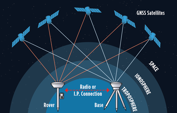
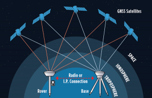
    Uncorrected GNSS is limited to precisions in meters. This may be fine for many purposes, such as coarse navigation and local-based apps. However, for high precision uses, external augmentations (commonly referred to as “corrections”) add more and higher accuracy data to help mitigate multiple sources of error that otherwise limit standalone GNSS results. Various augmented data can be delivered via radio, the internet, or communications satellites. Delivery of augmentations by public or commercial generators of this add-on data is broadly referred to as “positioning services.”

    Photo:
    Network RTK, implemented as real-time networks (RTN), covers hundreds of localities, states, and entire countries and is a go-to for many applications in surveying, mapping, construction, monitoring and agriculture. One disadvantage, compared to PPP, is reliance on terrestrial IP communications. (Images: courtesy of Gavin Schrock and Courtney Townsend
    Bigmouse108/iStock / Getty Images/Gettu Images)

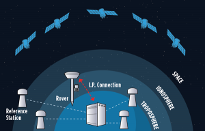
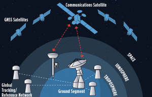
    There are two fundamental approaches to generating corrections: Observation Space Representation (OSR) and State Space Representation (SSR). OSR uses observations of one or more base receivers to derive correction values representative of local conditions. Examples of OSR include base-rover real-time kinematics (RTK) and network RTK (NRTK). SSR provides “states” of conditions derived from terrestrial tracking networks, to improve clock and orbit “products,” and may also include data from global, regional, or localized ionospheric and tropospheric models. Examples of SSR include precise point positioning (PPP) solutions.

    Players in the corrections services sector include vendors who manufacture GNSS hardware, RTK systems, and NRTK software. One example is real-time networks (RTN), which have grown to cover hundreds of localities, states, regions, and even entire countries. Some of these vendors now operate their own wide region RTN. The same large vendors also have developed global PPP services. The most recent decade though has seen rapid growth in new corrections service providers that focus on one or more key markets and develop approaches specifically to serve them. For instance, many agricultural regions of the world have large clusters of RTK stations operated by a vendor or a cooperative. Some newer vendors, focused on the autonomy market, have developed global PPP services, regional NRTK, or hybrids for decimeter to meter precision. One Achilles heel of PPP is its relatively poor vertical precision compared to RTK and NRTK. This partly explains why adoption has been slow for certain high-precision applications, such as surveying.

    Where corrections services have become quite interesting, is in amalgams of these approaches. In recent years, the rapid expansion of corrections services for mass-market applications has given rise to what developers call PPP-RTK. Ostensibly, this is to take advantage of the strengths in each approach, however it may be more about trade-offs between precision and the practicalities of serving wide regions in a cost-effective manner. There are many variations on how this hybridization is achieved; for example, PPP- ambiguity resolution (PPP-AR). PPP-RTK can be somewhat of a nebulous term, much in the same way as the term “AI” gets used. Developers of the specific PPP-RTK approaches for the many corrections services keep certain details close to their chests. Clients are less concerned with how it works as they are with the results.

    Examples of Vendors

    In compiling the following list, we tried to provide examples of all aspects of the corrections service industry — from GNSS network software development to hosting of national and regional networks to providing global PPP. This segment continues to grow; new players continue to develop solutions and enter the market, some with great fanfare, while others seek to stay under the radar. This list does not include the many hundreds of RTN worldwide — local, regional, or national — though the key providers of the NRTK software these networks use are listed.

    Photo:
    One advantage of PPP and PPP-RTK over RTK and NRTK is that they can deliver augmentations by satellites, eliminating reliance on terrestrial communications networks. Satellite delivery has a downside: the number of communications satellites broadcasting the augmentations is limited, which can be problematic in sky-view challenged areas. (Image: courtesy of Gavin Schrock and Courtney Townsend
    Bigmouse108/iStock / Getty Images/Gettu Images)

    Note that other vendors are also not listed, such as some that seek to limit their visibility to specific clients and partners. For example, some offer corrections services as an adjunct to inside hardware/software sales, and others work with developers of certain integrated navigation/autonomy systems. In addition, some of the smaller vendors may be working in conjunction with some of the more established developers, often licensing elements of their software, and in many instances piggybacking on their global tracking networks.

    In alphabetical order:
    Atlas. From Hemisphere GNSS. A global PPP service delivered by L-band satellites. It includes tiered precision for different applications, such as surveying, mapping, and asset management. Atlas Basic, Atlas H30, Atlas H10: bit.ly/3V42qxj.
    CHCNAV. CPS NRTK software: bit.ly/3FI6zlN. It also hosts various RTN and has a global network partner program: bit.ly/3VQugOr.
    CNH. Advance Farming Software (AFS) RTK+ network delivering corrections mostly via cellular to primarily precision agriculture users: bit.ly/3YiCZur.
    DigiFarm. DigiFarm VBN. An example of another network that serves primarily agriculture users, however, it now has a spinoff to serve other high precision markets: bit.ly/3hgnYZs.
    eSurvey. GNSS NET, a VRS management software: bit.ly/3Py0uMp.
    Fugro. Global PPP corrections services; tiered precision for various applications, mostly maritime and marine construction. StarFix, SeaStar, MarineStar, OceanStar: bit.ly/3W4LkA8.
    Geo++. One of the first developers of GNSS network and PPP solutions. Its GNSMART software suite provides NRTK and SSR broadcast capabilities: bit.ly/3FhGE2Z. 
    HERE Technologies. HD GNSS, a PPP-RTK solution for mass-market applications: bit.ly/3Fnle4H. 
    Hi-Target. Hi-RTP, a global PPP- RTK service: bit.ly/3hi2xHv. 
    IGS. International GNSS Service, a federation of agencies and research entities with a global tracking network of more than 400 reference stations. The IGS is a vital component of the global geodetic infrastructure. RTS is its real-time PPP service. It is not fast converging like many of the commercial services, but it is free for many applications. It is not broadcast via satellites, only via the internet: igs.org.
    Leica Geosystems. Part of Hexagon. Provider of NRTK software (Spider), and host of its own RTN covering various regions around the world (SmartNet), and global PPP (SmartLink): bit.ly/3uEwHb9. 
    NovAtel. Part of Hexagon. Includes various tiers of PPP-RTK: RTK Assist, RTK Assist-Pro*, TerraStar-L, Oceanix, TerraStar-C PRO*, and TerraStar-X* (what NovAtel calls “RTK From the Sky”): bit.ly/3HzuqWh. 
    Point One. RTK correction service called Polaris, available also via partners such as Bad Elf: bit.ly/3uPJGqA.
    Premium Positioning. RTK corrections service called RTK Premium: bit.ly/3uT0xZi. 
    Rx Networks. A mix of tiered positioning approaches for location- based applications. Truepoint. io (DGNSS, PPP, PPP-RTK): bit.ly/3We1rvT. 
    SBAS (Public). Satellite-based augmentation systems, national or regional services. Like commercial PPP, SBAS corrections are mostly served via satellites. Public safety and civil aviation are the primary drivers for providing such services. For instance, in North America, the Wide Area Augmentation System (WAAS) was chartered by the Federal Aviation Administration (FAA). There are equivalent systems in Europe (EGNOS), India (GAGAN), Japan (MSAS and QZSS), Russia (SDCM), China (SNAS/BDSAS, which is still in development) and Australia and New Zealand (SouthPAN). Other systems are in development in South America and the Caribbean (SACCSA), Korea (KASS) and in Africa and the Indian Ocean (ASECNA). 
    Sino/Comnav. CDC.NET CORS software, RTN software: bit.ly/3W56hvm. 
    Swift Navigation. Skylark RTK and Skylark DGNSS services: bit.ly/3HyWVn5. 
    Tersus GNSS. Tersus Advanced Positioning (TAP), a PPP service: bit.ly/3hoZkWD. 
    Topcon. TopNet and Topnet Live. RTN Software, regional RTN, and PPP services: bit.ly/3FRRcaw. 
    Trimble. RTN software, VRS Now (regional RTN), and tiered PPP services: CenterPoint RTX, RangePoint RTX, ViewPoint RTX, and FieldPoint RTX: bit.ly/3V3bbax. 
    u-blox. PointPerfect regional PPP and PPP-RTK: bit.ly/3FPVmQo. 
    Veripos. Part of Hexagon. Tiered global PPP services, originally focused on maritime applications: Standard, Ultra, APEX: bit.ly/3BBjfsf. 
    Verizon. Telecom infrastructure-based PPP-RTK service called ThingSpace: bit.ly/3Fw1U55. 
    Vodaphone. Currently developing corrections services in conjunction with Topcon: bit.ly/3Pug4s0. 

    Whatever the application, there are now many options for corrections services. Non-mass-market applications, for traditional high- precision uses, have been tapping such services for (in some cases) decades. The prize of primacy in the autonomy market has been in the sights of many of these vendors for many years, yet there have been relatively few real-world applications to date. That should be changing soon. Early adoptions such as GM’s Super Cruise, which is powered by the same core PPP technology as RTX, have been quite successful. Which will come out on top? That might be a moot question. With the potential of such markets so great, perhaps there is room for all of them, and more. 

  • Applanix: NOAA’s eye for hurricanes

    Applanix: NOAA’s eye for hurricanes

    Photo: NOAA
    High-resolution imagery geolocated by the sixth-generation Digital Sensor System (DSS) after Hurricane Ida. (Photo: NOAA)

    Applanix, a division of Trimble, has been working with the National Oceanographic and Atmospheric Administration (NOAA) since the early 2000s to develop their response for emergency and coastal mapping activities. We discussed this collaboration with Joe Hutton, the company’s director of inertial technology, land and airborne products.


    How has Applanix collaborated with NOAA regarding emergency response and coastal mapping?

    Early on, we worked with them to develop a solution that allowed them to get out in the field and produce high accuracy map products with minimal touching of the data. In mid-2021, we delivered the next generation of this solution, or the DSS version six, which represents the culmination of everything learned over the years about how to produce imagery for emergency response, in terms of the types of collection, the types of imagery, and how to get it into first responders’ hands as quickly as possible.

    At the heart of the system is our direct georeferencing technology. It’s a solution that allows us to assign the geographic location of every pixel of the digital imagery collected in the air. As soon as you land, you have the coordinates of every pixel, which means that you have a map that NOAA then pushes to the cloud for first responders to use in their emergency response efforts.

    The collaboration consisted of Applanix working with Lead’Air to manufacture the next generation system that meets NOAA’s latest requirements. That’s what we delivered in 2021. Weeks after delivery, NOAA was called to respond to the hurricanes. They flew the new system with great success and were able to use it for their response.

    What is your perspective on ground control points (GCPs) vs. direct georeferencing?

    It is impossible to place GCPs in an emergency response when you cannot get on the ground. People who say they need GCPs do not really understand direct georeferencing. We’re having this debate even after 20 years of proving this technology. The NOAA system does not use GCPs and the map products are at centimeter level accuracy.

    We use Trimble’s RTX technology, which enables centimeter-level GNSS positioning without base stations, which is important when the CORS or local RTN is unreliable due to a disaster. We have high accuracy inertial systems that get us the high accuracy orientation, so that we can go directly to ortho photos and ortho mosaics without running any triangulation or using GCPs in that process. That is a standard process these days. GCPs are only there for quality control if you want to deliver a final map product.

    Did NOAA fly the mission with its own aircraft?

    Yes, these are NOAA’s King Air or Twin Otter aircraft. The King Air aircraft is specifically outfitted for these types of emergency response and coastal mapping activities. The DSS system gets installed into the airplane and gets calibrated in terms of checking the system out for accuracy. Then it’s ready to fly the response. In the air, they collect the imagery over a flight path of interest to them. Then, it’s developed from raw imagery into JPEGs in the aircraft, and all the georeferencing data is logged with that imagery so that as soon as they land they can push a button and start to reference the JPEG imagery and push it to the cloud.

    What are the components of your system?

    What makes this system so unique is that it encompasses all the lessons learned over the years in terms of what NOAA needs to optimize for both their coastal mapping and their emergency response. It incorporates two pairs of color and near-infrared Phase One cameras that are configured in an oblique format with some overlap, forming a bowtie footprint on the ground.

    You have 100% overlap of the color with the near-infrared and it’s on a high-performance stabilized mount that keeps everything perfectly level. The mount also has a special feature that enables the operators to rotate the cameras to go into nadir mode, mostly for traditional coastal mapping that requires stereo imagery. We were able to incorporate into a single system the requirements for both emergency response—where you want large coverage and obliqueness to look for damage—and nadir for coastal mapping.

    Lead’Air built the sensor for you, on your specs, correct?

    Yes, that’s correct. We’ve worked with Lead’Air for probably 20 years on flight management system (FMS) technology. They also have an amazing capability to build stabilized mounts and hardware systems. So, we decided to work together. We contracted them to implement some of their innovative hardware in this new design for us to deliver to NOAA. We contracted them to do all the manufacturing of the design and delivery to NOAA.

    One of the quite innovative things that they did was to develop a new flight management capability that allows NOAA to fly ad hoc along highways or rivers, looking for damage. Traditionally, for aerial imagery you have to pre-flight plan trajectories. They designed an FMS that enables a pilot to fly a road or a river looking for damage without worrying about traditional block collections as with a more traditional FMS. So that feature further increases productivity. If you look at the most recent imagery at www.storms.ngs.noaa.gov you will see that it looks like spaghetti, not like blocks. That’s because they are following the roads and the rivers looking for specific damage.

    Does the post-processing use your software?

    Yes, it uses the POSPac MMS post processing software with POSPac Trimble Post-processed CenterPoint RTX correction service, allowing us to get that centimeter-level position accuracy, anywhere in the world with just an internet connection. You don’t have to worry about having a local base station—which, of course, if you’re in an emergency response situation, might not be there anyway. So, this is a very powerful way of getting global centimeter-level accuracy in real time, without having to worry about the ground-based GNSS infrastructure, that is, the local real-time network, that’s on the ground.

    If you don’t have internet access, you can ship that data to the nearest place that does, right?

    You could, however NOAA simply flies to wherever there is access. What takes the longest is to develop the imagery from the raw format to the JPEG format, because these are such large images. Doing that in the air saves an enormous amount of time. You have these JPEG-ready images that are compressed and can go right into the georeferencing process and make it really, really fast.

    That’s a matter of computing power and smart software. What else did Lead’Air contribute?

    This very efficient, fast image development process in the aircraft.

    It sounds like it was a very integrated process between Applanix and Lead’Air. So, NOAA had the instrument mounted on their aircraft, their pilots did the flying, and then you processed the data?

    No, NOAA’s team processes all the data. We just deliver the hardware and the software. They created the workflow software to push the data to their cloud environment.

    NOAA uses this data to produce maps of the damage and highlight different situations and hazards?

    Yeah. When these hurricanes go through, the first questions people have are “Where’s the damage? Are these roads passable? Did my house survive?” If you are doing response, you need to get teams in there. First, however, you need to know whether the roads are passable, so that you will not waste time going down a road that is not. So, the first thing they do is go up in the air and survey the main roads to push the imagery back, so that people can assess whether the roads are passable. Then they start to look for specific areas of damaged infrastructure, to triage where to put their resources. Then they ask “How do we manage disaster recovery?”

    What lessons did you learn?

    We are still learning about the power of the system, because these are Phase One 150 megapixel color cameras. It is such a powerful combination of sensors that they’re starting to look at different information they can get out of these things. They’re still learning new lessons in terms of what information can be useful for both the emergency response and the coastal mapping.

    Ultimately, we’ll go to full ortho maps in the aircraft. That’s just going to be a matter of computational power. The holy grail would be to produce an orthophoto in the aircraft and radio it down to the ground in real time. Nothing prevents you from doing that now other than computational power and bandwidth. It’s not practical yet, but it will probably get there.

    Do you have collaborations like the one with NOAA with any other major U.S. agencies?

    We’ve worked extensively with NASA over the years. For example, we have worked with them on the ice bridge project. That is where they survey ice at both poles to measure its thickness and how global warming is affecting it. They use our system on that to do the georeferencing. We also work extensively with other branches of NOAA for their shoreline mapping from their ships. We have worked with them over the years to provide the georeferencing solution for the multibeam echo sounders to produce their nautical charts.

  • NGS Beta OPUS released, accepting RTK and post-processed data

    NGS Beta OPUS released, accepting RTK and post-processed data

    On Sept. 16, the National Geodetic Survey (NGS) released the latest beta version of OPUS, called Beta OPUS Projects 5.0.  This version of OPUS now accepts real-time kinematic data and post-processed GNSS vectors from vendor software. See the box titled “Beta OPUS Projects 5.0 Webpage” on the website.

    As stated in the announcement, NGS has developed a file format for submitted real-time kinematic (RTK) data and post-processed GNSS vectors from vendor software to NGS. It is denoted as GNSS Vector Exchange Format (GVX).  This format enables NGS to incorporate the data into its GNSS processing routines.

    This is similar to the original Receiver Independent Exchange Format (RINEX) developed for making post-processing more efficient when combining GNSS data from manufacturers outputting raw GPS data in varying file formats. In my opinion, this is a significant improvement to NGS’s OPUS web utility.

    Beta OPUS Projects 5.0 Webpage

    Image: NGS website
    Image: NGS website

    Users can obtain background information about the GVX file format by clicking the link GVX file format. More detailed information about the GVX format can be obtained by clicking on the Documentation link.

    GNSS Vector Exchange File Format Webpage

    Image: NGS website
    Image: NGS website

    Basically, GVX is a standardized format for exchanging GNSS vectors derived from GNSS survey data using any manufacturer hardware and software results (see the box titled “Excerpt from Documentation of GVX”).  NGS designed the format so that it included all of the necessary data (including metadata) of a GNSS vector for incorporation into a survey network for performing a least-squares adjustment.

    Excerpt from Documentation of GVX

    (Link to PDF of GVX Documentation)

    To this end, this document proposes a new standardized file format known as the GNSS Vector Exchange Format (GVX). GVX aims to provide a standard format for exchanging GNSS vectors derived from varying GNSS survey methods and manufacturer hardware. The file format includes all of the necessary data of a GNSS vector for inclusion in a survey network for least squares adjustment, as well as metadata which describes the vector. The format is meant for any type of GNSS vector, whether it was derived in real-time or from baseline post-processing. GVX has been written in extensible markup language (XML). XML was chosen because it was designed to carry and store data in plain text format, it is easy to expand and/or upgrade to new operating systems, and it can be read by both humans and machines.

    A sample GVX file can be obtained by clicking on the link titled “Example of GVX file, project day 066, day 052, day 053, day 054.” As NGS states in the documentation, the output can be read both by humans and machines. What’s important is that it can be read by machines so the information can be incorporated into software programs. GNSS vendors have all the information they need to generate the output file to enable users to import the data into OPUS Project 5.0. Users will have to contact their software providers to determine whether their software routines generate the GVX output files.

    Example of GVX file, project day 066

    Image: NGS website
    Image: NGS website

    As I previously mentioned, this new option in OPUS Projects 5.0 is a significant improvement because many surveyors use RTK networks to obtain coordinates of marks. It will also facilitate the occupation of benchmarks with GNSS equipment to support the NGS 2022 Transformation tool. North Carolina, my home state, has a real-time network (RTN) that includes 96 GNSS CORS. (See the box titled “NC GNSS CORS and Real-Time Network.”) Currently, the North Carolina GNSS CORS and RTN has 4584 RTN service subscriptions.

    NC GNSS CORS and Real-Time Network

    Image: North Carolina Geodetic Survey Website
    Image: North Carolina Geodetic Survey Website

    I could not find a current list of public RTK networks in the United States, but I did locate a Jan. 7, 2014, GPS World article by Eric Gakstatter that provided a list of public RTK base stations in the country. It’s not up-to-date, but it highlights that, more than seven years ago, more than half of the U.S. states  had some kind of public RTK network. I would like to update the table, so I’d appreciate receiving information on the status of any public RTK network. Please feel free to send me an email at [email protected].

    List of Public RTK Base Stations in 2014

    Based on GPS World 2014 Article by Eric Gakstatter

    Note: States not listed did not have a public RTK network.

    State

    Status of Public Network

    Alabama Alabama Department of Transportation. Leica network.
    Alaska Two PBO RTK bases. One in Fairbanks and one in Palmer. Otherwise, no public service.
    Arizona Arizona State Cartographer’s Office. Leica network. Plate Boundary Observatory (single baseline).
    California California Real Time Network (CRTN) (single baseline).  Plate Boundary Observatory. Single baseline.
    Colorado Mesa County (Trimble network) and Plate Boundary Observatory (single baseline).
    Florida Florida Department of Transportation. Leica network.
    Idaho Plate Boundary Observatory (single baseline).
    Indiana Indiana Department of Transportation. Leica network.
    Iowa Iowa Department of Transportation. Leica network.
    Kentucky Kentucky Transportation Cabinet. Trimble network.
    Louisiana Louisiana State University. Trimble network.
    Maine Maine Department of Transportation. Trimble network.
    Massachusetts Massachusetts Department of Transportation. Leica network.
    Michigan Michigan Department of Transportation. Leica network.
    Minnesota Department of Transportation. Trimble network.
    Mississippi University of Southern Mississippi. Trimble network.
    Missouri Missouri Department of Transportation. Trimble network.
    Montana Plate Boundary Observatory (single baseline).
    Nevada Washoe County. Trimble network. Las Vegas Valley Water District. Leica network. Plate Boundary Observatory (single baseline).
    New Mexico Plate Boundary Observatory (single baseline).
    New York New York Department of Transportation. Leica network.
    North Carolina N.C. Department of Environment and Natural Resources. Trimble network. $500 one-time sign-up fee.
    Ohio Ohio Department of Transportation. Trimble network.
    Oregon Oregon Department of Transportation. Leica network. Plate Boundary Observatory (single baseline).
    South Carolina South Carolina Geodetic Survey. Public but charges a usage fee. Trimble network.
    Tennessee Tennessee Department of Transportation. Public but charges a usage fee. Topcon network.
    Texas Texas Department of Transportation. Public but only available to TxDOT employees and TxDOT contractors. Trimble network.
    Utah Utah Automated Geographic Reference Center.  Public but charges a usage fee. Trimble network. Plate Boundary Observatory (single baseline).
    Vermont Vermont Geodetic Survey. Trimble network.
    Washington Washington State Reference Network (Seattle Public Utilities). Trimble network. Public but charges a usage fee. Pierce County (Leica Network). Plate Boundary Observatory (single baseline).
    West Virginia West Virginia Department of Transportation. Trimble network.
    Wisconsin Wisconsin Department of Transportation. Trimble network.
    Wyoming Plate Boundary Observatory (single baseline).

    Why do I believe that this new option in OPUS Projects 5.0 is so important? Because it facilitates the incorporation of accurate GNSS-derived ellipsoid and orthometric heights into the National Spatial Reference System (NSRS).  With the development of improved algorithms, the results of coordinates computed using GNSS CORS/RTNs are more accurate today than ever before. During the last decade, there have been many studies analyzing GNSS data to estimate the accuracy values of coordinates from RTN data.

    A study titled “Accuracy of GNSS Observations from Three Real-Time Networks in Maryland, USA” by Daniel Gillins, Jacob Heck, Galen Scott, Kevin Jordan and Ryan Hippenstiel presented at FIG Working Week 2019 in Hanoi, Vietnam, April 22–26, 2019, provided a comparative evaluation on the accuracy of three independent RTNs constructed with differing hardware and software. Their study was based on 486, 5-minute duration GPS + GLONASS network RTK (NRTK) observations. The results indicated that repeat NRTK vectors could be combined to meet 1 cm horizontally and 2 cm vertically (ellipsoid height) accuracies at 95%. confidence.  See the box below.  It should be noted that the repeat observations should be observed at different times of the day (for instance, separated by > 2–3 hours), as well as, in my opinion, if possible at least more than two different days.

    Conclusions from Daniel Gillins, et al. 2019 FIG Paper

    A total of 486, 5-min duration, GPS+GLONASS NRTK observations were collected on nine bench marks distributed over a 4,000 square km area with rovers connected to three different RTNs in Maryland. Each RTN was developed with equipment and software from a different manufacturer, yet all three RTNs performed similarly in terms of accuracy. When differenced with coordinates from a static GNSS survey campaign, the horizontal and vertical RMSE of the NRTK-derived coordinates was 2.3 cm horizontally and 4.5 cm vertically at 95% confidence. Repetitive NRTK vectors on each baseline differed between ± 2.4 cm horizontally and ± 3.4 cm vertically at 95% confidence. As a final accuracy evaluation, hybrid survey networks consisting of repeat NRTK vectors and baseline solutions from post-processing static GPS data collected at RTN base stations and CORSs were adjusted by least squares. Prior to adjustment, the VCV matrices of the vectors were scaled by variance-component estimation. Adjustment of hybrid survey networks with four repeat NRTK vectors per bench mark produced network accuracies at 95% confidence for the adjusted coordinates at all bench marks less than 1 cm horizontally and 2 cm vertically (ellipsoid height). In addition to the benefits of using efficient and accurate NRTK vectors, the hybrid survey network approach makes use of redundant vectors for checking data and avoiding blunders. The approach also provides traceability because the NRTK vectors are tied to an RTN base station which is tied to CORS. Finally, these networks ensure the survey is referenced to the published coordinates of the CORSs which are held as constraints in the adjustment.

    Lastly, I would like to remind users that only three months remain until the December 31, 2021, cutoff to submit GPS on Benchmarks data that NGS can guarantee will be analyzed to compute the initial set of 2020.0 Reference Epoch Coordinates (RECs) that will be released with the Modernized NSRS. This initial set of RECs is currently the only set that NGS can guarantee will be used to build the 2022 Transformation Tool.  Once the transformation model is finalized, the NAVD 88 – NAPGD 2022 transformation values will be locked in and will not be updated as additional sets of RECs are computed.  If you have questions or concerns about this cut-off date, please contact your NGS Regional Geodetic Advisor, or drop NGS a line at [email protected].

    Beta OPUS Project 5.0 is a web-based tool that makes it easier to submit data to NGS.  I would encourage NSRS users to occupy as many benchmarks with GNSS equipment and submit the data to NGS before the Dec. 31 deadline.  Not only will these data help in improving the transformation model, but the marks will be included in the first computation of Reference Epoch Coordinates (RECs).  You can obtain information about Reference Epoch Coordinates in NGS’s NOAA Technical Report NOS NGS 67 publication titled “Blueprint for the Modernized NSRS, Part 3: Working in the Modernized NSRS.” A future column will address the different types of coordinates that will be distributed by NGS with the modernized NSRS.

  • The hazards of mixing RTK bases

    The hazards of mixing RTK bases

    Single-base RTK is an excellent choice for many uses but mixing different baseline lengths can yield inconsistent results

    By Gavin Schrock, PLS

    Gavin Schrock, PLS
    Gavin Schrock, PLS

    The surveying lead for a construction firm started getting calls from his crews — suddenly they were not checking in to existing control with the accuracy required. This presented a conundrum and an immediate resolution was needed to stay on schedule. What had changed? A nearby permanent base, part of the regional real-time GNSS network (RTN), had suddenly gone dark, and when the crews switched to other bases, they got the inconsistent results. Time to call the RTN. (See a primer on RTN.)

    I have been operating a regional cooperative RTN for 19 years, and I get these kinds of support calls regularly, but typically only from users of the single-base mountpoints. Most RTN provide, via NTRIP casters, both network RTK (NRTK) solutions — such as master-auxiliary, VRS and FKP — and single-base solutions for each base. The base they had been using was down while the roof of the city building on which it is mounted was undergoing some maintenance.

    The construction firm, halfway through a multi-year transportation project, had used the base when they established project control, and for layout and as-built tasks. Using the base, which was slightly more than 4 km from the site, the crews were used to seeing check-in results of 0.3′ (9 mm) or better (horizontal). When they switched to different bases, 23 km and 25 km distant, the results were now inconsistent, and in many instances, double.

    This was an easy fix. We met on site and checked results using the network solution; it closely matched the results they were seeing from the original base. Until the original base was restored, this would meet their needs.

    It made a lot of sense to use the nearby base, as setting a temporary project base on the congested and sky-view challenged site was impractical. Furthermore, the baseline length of 4 km yields excellent results. Single-base RTK is a powerful tool, and a default for many construction projects, provided that:

    • the base has an unobstructed view of the sky
    • the base is free of nearby multi-path hazards
    • the base receiver and the antenna are of the same or better quality as the rovers
    • the base receiver and the antenna support the constellations and the signals desired.

    In many ways, it is hard to beat single-base RTK. For instance, if you set up a base right on the site, say less than a kilometer away, this should yield the best results possible for RTK, and can be better than network RTK.

    However, there are challenges. Single-base, typically “iono-free” solutions common in today’s rovers, degrades over the baseline length. The rule of thumb for many is that the degradation becomes noticeable when baseline lengths exceed 10 km. It is not uncommon for rovers to fix at much longer baseline lengths; 20 km, 30 km, 50 km or more — but results will likely vary from hour to hour or day to day. Changes in ionospheric and tropospheric conditions can bring inconsistencies, particularly over longer baseline lengths.

    Network RTK may not beat single-base over very short baselines, but as it uses 5 to 15 bases (depending on the implementation) it can better model in the varied conditions. It can provide great consistency and repeatability, even if an individual base is unavailable, as was the case for this conduction site. There are strengths and weaknesses for both. NRTK brings consistency over a wide area, you do not have to set up (and guard) your own base, and the geodetic values are solved.

    If you can have an on-site base, you can under certain conditions see a gain in results. This is especially important for certain applications, such as machine control and precision agriculture, for which tight year-to-year and row-to-row repeatability is key. However, if you may need to use another base at some point, you may be better off starting with NRTK, if it yields the results you seek.


    Gavin Schrock is a practicing surveyor, technology writer, editor of xyHt Magazine and operator of a cooperative GNSS network.

  • Trimble introduces next-generation GNSS reference receiver

    Trimble has introduced its next-generation GNSS reference receiver for real-time network (RTN) applications: the Trimble Alloy GNSS reference receiver.

    With 672 channels, the continuously operating reference station (CORS) receiver provides users and operators with access to multiple constellations and signals, supplying robust and reliable reference data.

    With an IP68 rating for protection against dust and moisture, the Trimble Alloy performs even in the most rugged environments to meet the demands of professionals from the earth science, surveying, construction, mapping and agricultural industries.

    Delivering high-accuracy GNSS data to improve RTN performance and reliability, the Trimble Alloy GNSS receiver allows RTN owners and operators to:

    • Track and log all current and planned GNSS. Powered by the new Trimble Maxwell 7 GNSS dual chipsets, Trimble Alloy tracks and processes all of today’s current GNSS signals at data rates up to 100Hz, and is designed to be ready for planned signals and systems. The next generation receiver provides 672 channels for unrivaled GNSS constellation tracking including: GPS, GLONASS, BeiDou, Galileo, QZSS, IRNSS as well as the full range of SBAS.
    • Deliver absolute position monitoring. Leveraging Trimble RTX precise point positioning technology, the Trimble Alloy receiver is able to derive its position at centimeter-level accuracy in real-time. Combined with Trimble’s advanced Sentry monitoring technology, the receiver will automatically notify the operator of any status change including positional changes. The technology ensures users are receiving the most accurate correction data.
    • Realize new levels of user convenience. An all new intelligent receiver design brings an unprecedented level of usability to GNSS reference stations with the Trimble Alloy reference receiver. Featuring a tilted four-line OLED screen, Trimble Alloy displays key information without the need for scrolling through multiple menus. Dual hot swappable batteries, coupled with multiple power inputs, give users flexible installation options. Wi-Fi connectivity, multiple serial ports and remote access options allow users to configure the device easily, no matter how or where it’s installed.

    “Alloy provides a solution to address a variety of installation challenges faced by RTN owners and operators today,” said Mark Richter, marketing director of Trimble’s Advanced Positioning Division. “The receiver can track all satellite signals at the highest possible data rate while being easy to use, access and configure. All of these features make the receiver a compelling investment for owner/operators who are looking to modernize their networks or single station configurations. Trimble Alloy will carry them far into the future.”

    The Trimble Alloy GNSS reference station receiver is expected to be available in most of the world through Trimble’s Distribution Channel during the first quarter of 2018. For Asia and Latin America, the receiver is expected to be available in the second quarter of 2018.

  • Accuracy, precision and boundary retracement in surveying

    Accuracy, precision and boundary retracement in surveying

    Technology has improved the scientific community’s ability to measure in many ways that our ancestors would have trouble believing. From obtaining measurements across galaxies down to the tiniest of atom splitting, our ability to measure is exceedingly robust. The land surveying profession has benefitted from this ongoing technological revolution in many ways (GPS World March 2017) and has advanced our work in many new directions never thought possible. Substantial increases in precision through these advancements allows the land surveyor to perform various tasks, including topographic surveys, construction layout and volumetric surveys with increased confidence.

    Graphic: https://sites.google.com/a/apaches.k12.in.us/mr-evans-science-website/home

    Accuracy and precision are two factors that go into our measurement procedures. While accuracy and precision are considered to be the same thing by a large portion of the population, it couldn’t be more from the truth. Accuracy is defined on how well a measurement or reading is in relation to a known value or benchmark. Precision, on the other hand, is how closely a measurement is repeated yet has no relation to any given value or benchmark.

    The introduction of GNSS technology along with total stations with locking electronic distance measuring (EDM) mechanisms in the 1980’s brought more precision into the hands of the surveyor. These innovations reduced the amount of human error in our measuring procedures when used in an appropriate manner as well as allowing greater distances to be covered. The implementation of various real-time networks (RTN) on several continents also continues to increase our range of high-precision location and measurements worldwide. However, as we develop our next generation of surveyors through educational programs and apprenticeships, we are making a terrible mistake in replacing many fundamental land surveying principles and legal precedents with more emphasis on precision and less on legal accuracy based upon precedents.

    Surveyors and the role of measurement

    In ancient civilization, the primary role of the land surveyor was to help establish and maintain property boundaries. Measurement devices included knotted rope, the Gunter chain and the compass, all used is varying manners and precisions. Paramount to the surveyor’s effort was the establish of monuments at corner points of the tracts they were measuring. These points were held as the ultimate dividing point and superior to associated measurements and secondary tie points. This simple guide for all surveyors has been a core principle of property owner’s rights and upholding those rights in the name of the law. By placing of monuments, the landowner has relied on the surveyor to physically define the property being established and conveyed.

    Let’s ask Washington, Jefferson and Lincoln…

    For example, in early days of the United States during the late 1700’s/early 1800’s, once an original survey was completed, notes of each survey were preserved by various means. Most governmental surveys of the early 1800’s were transcribed onto large township sheets in order to perpetuate and preserve the work performed by the Land Office surveyors. The establishment of states and local governments brought forward land and records offices in which these government patent lands were further subdivided for conveyance to settlers of the new lands. In each of these cases, corners of various types were set to distinguish boundaries between property ownership. Wooden posts, rock mounds, and other materials were used to physically mark the locations of the corners, with notes, documentation and deeds for conveyance coming after the determination of the property. Regardless of any variation from the notes/plats/deed descriptions, property rights were held to the physical locations of the markers set during the course of the survey.

    The American dream of land ownership

    As more people moved westward and parcel subdivisions became more prevalent, planned developments began to be based upon pre-calculated figures. Before calculators and computers, the surveyor would determine the location of new parcel corners by hand derived calculations (usually in the field) and use a transit and chain to stake each parcel corner. Notes were carefully kept during the lot creation process and transferred to a final plat for filing at the county recorder’s office. These plats were typically post-survey with the detailed notes being drawn on the plat with specific dimensions to all points set.

    As plane geometry and coordinate systems caught on (GPS World November 2016), the movement toward pre-calculated subdivisions became more common. Couple this method of calculation with increased capability of high precision theodolites and the World War 2 postwar boom, the economy and environment was ready for more time efficient surveys. Now large parent parcels were being subdivided on paper before any additional surveying was performed to establish the new lotting configuration. Surveyors began to stake parcel corners by means other than “running the lines”, i.e. physically occupying the outer boundary and setting internal points for new parcels. Add to this environment of “faster” surveying the invention of the EDM, digital total station, computer programming and analysis along with GNSS, and now we have a recipe for the most precise and accurate surveying ever performed. Or do we?

    These are not your father’s (or grandfather’s) survey methods anymore

    Regarding topographic, volumetric, bathymetric and aerial surveys, I would agree that technology has advanced our profession to greater heights. These tasks have benefited greatly by increased data collection, remote location and sensing and computing power. The surveyor’s ability to provide an extremely detailed set of data for varying surfaces and site conditions is at an all-time high with more technology continually being developed. But how has technology affected our primary role of boundary line expert? While in many ways as technology has helped the boundary survey, it has also taken away from the surveyor’s responsibility and duty as expert measurer. The intent of the surveyor is mostly clear when retracing a prior survey or creating new parcels from existing ones but execution, along with mistakes/errors/blunders, throw ambiguity into the fold. Not knowing where to find a random error within a prior survey leads many practitioners down a long and frustrating path. In a perfect world, the math would all work out and everything fits together like a glove. However, due to many variables and errors that randomly and systematically happen during our work, this condition is near impossible to attain. This quote is from the “Illinois Boundary Law” book written by land surveyor/attorney Jeff Lucas in 2012 sums it up well:

    “There is an irresistible urge on the part of many surveyors to trust math and measurements over their understanding of boundary law principles. When this misplaced trust is coupled with the confusion over the land surveyor’s duties and responsibilities, the land surveyor is free to ignore clear-cut doctrines of law when precision expectations come into conflict with the realities that are found on the ground.”

    So, what does this mean? Many of the legal descriptions surveyors have been charged with to perform a boundary survey were created using equipment, techniques and simple math far inferior to today’s standards. For example, a survey in downtown Chicago may be based upon a plat from the early 1800’s, (if the record happened to survive the Great Fire of 1871) and was depicted in chains and links. We now have surveyor who show all dimensions to the 1/1000th of a foot on these boundary and land title surveys. Considering that most of the surveys from that era only had a precision of one link (0.66 ft.), it could be considered overkill to need to be that precise. I’m in agreement that the survey must depict the current conditions and properly define where boundary rights are physically located, but to show that many significant figures is careless and unnecessary.

    For surveys on larger parcels and in rural areas, GNSS use (and abuse) now comes into play much more often. As I’ve written previously (GPS World May 2016) GNSS implementation is the single greatest advancement of surveying technology in my opinion. The ability to survey significant areas with great precision still impresses me and I wouldn’t trade it for anything. But notice I stated “precision” and not accuracy and this is where many surveyors get off track; hence, the statement from Mr. Lucas.

    You’re not the original; you’re the retracement

    While a small proportion of surveys completed today are for government lands and follow the Bureau of Land Management’s Manual of Surveying Instructions (2009 Edition), the remaining surveys are broken into two categories by whom they are performed by: the original surveyor or the retracement surveyor. This is best described from the text of the well-known Florida court case of Rivers v. Lozeau (539 So.2d 1147 (Fla. App. 5 Dist. 1989):

    “First, the surveyor can, in the first instance, lay out or establish boundary lines with an original division of a tract of land which has theretofore existed as one unit or parcel. In performing this function, he is known as the “original surveyor” and when his survey results in a property description used by the owner to transfer title to property that survey has a certain special authority in that the monuments set by the original surveyor on the ground control over discrepancies within the total parcel description and, more importantly, control over all subsequent surveys attempting to locate the same line.

    Second, a surveyor can be retained to locate on the ground a boundary line which has theretofore been established. When he does this, he “traces the footsteps” of the “original surveyor” and locating existing boundaries. Correctly stated, this is a “retracement” survey, not a resurvey, and in performing this function, the second and each succeeding surveyor is a “following” or “tracing” surveyor and his sole duty, function and power is to locate on the ground the boundaries corners and the boundary line or lines established by the original survey; he cannot establish a new corner or new line terminal point, nor may he correct errors of the original surveyor. He must only track the footsteps of the original surveyor. The following surveyor, rather than being the creator of the boundary line, is only its discoverer and is only that when he correctly locates it.”

    The surveyor’s role in boundaries, period

    To further illustrate the surveyor’s role in each type of survey, let’s examine the recent publication of “Boundary Retracement Processes and Procedures” by Donald A. Wilson, a long-time land surveyor and prolific writer of surveying manuals. Don’s book delves deep into all things concerning the role of the land surveyor in completing a property retracement survey. While surveying does rely heavily on good measurement techniques, it goes along with a handful of other talents as well. Don’s book revisits a 1985 Vermont Society of Land Surveyor’s publication “Cornerpost” (VSLS Cornerpost) that contained an article titled “What does a land surveyor do?” written by George F. Butts. In the article, George lists in detail that besides the prerequisite surveying knowledge, the surveyor must also have some aspect of skills for the following disciplines: archaeologist, astronomer, cartographer, computer specialist, dendrologist, detective, engineer, farmer, forester, geologist, handwriting expert, historian, hydrologist, lawyer, logger, judge, juror, photogrammetrist, writer, and expert witness. Notice that George didn’t include mathematician or statistician, both disciplines that rely heavily on the study of formulas, figures and data. While surveying computations relies heavily on geometry and trigonometry, the first order of business in data analyzation is how it relates back to the “original survey.” This brings us back to the primary role of the land surveyor – “following the footsteps.” As Don quotes; “…following the footsteps of the original surveyor is the legal standard adopted by the courts in all jurisdictions, and for very good reason.” The intent of the retracement surveyor is to uncover the past through all necessary information and bring to life the original survey. How the surveyor gets there, through the muddied use of technology, often leads us down the wrong path. He also adds from the 1818 South Carolina court case of Bradford v. Pitts (2 Mills. Const. Rep 115); “Blind devotion to a rule may lead to infinite failure.”

    Back to the Stone Age?

    So, what is the answer? Do we throw out all the electronic tech and time-saving methods in order to retrace all surveys with compass and/or transit and chain? Of course not. I do ask that all surveyors look at what the profession has charged them with and how they use their tools to get there. For instance, I am thankful for all the medical breakthroughs in the past 100 years, especially when it comes to technology. Imaging machines, robotic laser procedures for internal surgeries and more come to mind, but let’s remember that doctors still look at the human element and not just what a computer spits out as a diagnosis. How many times have you looked up your symptoms on WedMD and decided you were dying from that rash? Surveyors are doing the same thing with analyzing data from the mathematics view and not from the boundary law principles view.

    It’s not all just about the location data

    High-precision GNSS locations (and conventional data) we collect as surveyors needs to be included with the analyzation of the historical data from the legal side of the survey. If we didn’t find the original points, did we find ones that were substantially close to where the originals were? Were any of the original conditions at the time of the survey still intact? Bearing trees? Buildings? Any reference ties? What most surveyors tend to forget well is that all measuring devices (and I do mean ALL) are not the same, no matter how close they are manufactured and calibrated. Couple that with mistakes/errors/blunders I spoke of earlier, and here is your recipe of inconsistencies between surveys. You will say your instruments and devices are in top condition, so your data is right and the previous surveyors obviously messed something up. The unfortunate thing is that almost every surveyor makes that statement and we all are wrong to some degree. The bottom line is that while we may collect a ton of data with the upmost precision, it may not be accurate with the intent of the project, which is to retrace the original survey to the best of your ability. I’m not advocating that we dump our fancy robots, our very handy RTN networks or my shiny new UAV; instead, let’s get back to the basics. As Don Wilson notes in his preface of the new book; “One of the biggest differences between the surveyor relying on principles and court relying on precedent is that courts continually revisit the reason for the rule, or the decision in the previous case, to ensure that it applies, and fits the issue.” What I am advocating is that we remember the duties of our role and utilize the necessary tools to perform and deliver to the best of our abilities. I’ve had mentors and teachers that relied heavily on the math and not so much the true legal definitions. That means we need to brush up on the law and precedents that have been established for various situations and reasons. It will be through continuing education of our everchanging profession that will open more surveyor’s eyes to what the role of the surveyor was truly meant to be. With no disrespect to the GIS world, surveyors don’t aspire to be a map makers or database managers. We are professional land surveyors and our duty to our clients includes professionalism and the completion of an accurate land survey through precision measurement and analysis. Just as long as we follow those footsteps…