The GPS Next Generation Operational Control System program of the U.S. Space Force has been cancelled by the Defense Acquisition Executive, based upon the recommendation of the acting service acquisition executive.
OCX was intended to update command and control of the GPS satellite constellation, replacing the current system, known as the Architecture Evolution Plan (AEP), as well as replacing the Launch, Anomaly and Disposal Operations system. However, the program was unable to deliver needed capabilities on an operationally relevant timeline at an acceptable level of risk to meet the GPS constellation modernization needs.
“It’s important we refine and update acquisition processes to prioritize rapid, incremental capability delivery versus complex ‘all or nothing’ system deliveries,” said Acting Service Acquisition Executive Tom Ainsworth. “The Department of War [Defense] has made clear that we need to deliver warfighting capability at a faster rate. We must continue to work with industry to meet the needs of our warfighters as we focus on delivering the right technology on the right timeline to enhance our capabilities and maintain space superiority.”
In July 2025, following a multi-year regimen of factory testing, the Space Force contractually accepted OCX from RTX (Raytheon) and began extensive integrated systems testing to resolve liens carried over from factory testing, as well as to ensure the system could operate within the broader GPS enterprise of ground systems, satellites, and user equipment.
As of January 2026, the program cost was approximately $6.27 billion which included complete Raytheon funding to date and other government costs, such as the cost of government testing and support costs to the OCX acquisition program office.
“Regrettably, extensive system issues arose during the integrated testing of OCX with the broader GPS enterprise,” said Mission Delta 31 Commander Col. Stephen Hobbs. “Despite repeated collaborative approaches by the entire government and contractor team, the challenges of onboarding the system in an operationally relevant timeline proved insurmountable. We discovered problems across a broad range of capability areas that would put current GPS military and civilian capabilities at risk.”
Because of past delays on the OCX program, the Space Force has made incremental improvements over the last 10 years to AEP. These successful upgrades provide confidence that further upgrades to GPS ground systems will continue to support the enterprise and deliver new capabilities.
“Ultimately, we analyzed the work remaining on OCX and compared this with the current GPS control system capability,” Hobbs said. “The analysis revealed additional investment in OCX was no longer the best solution for protecting and advancing GPS capabilities. Instead, we will continue enhancing the current control system to operate the GPS satellite constellation.”
The U.S. Space Force is considering canceling the contract held by RTX (formerly Raytheon) to develop the GPS III ground control system, according to a report in Air & Space Forces Magazine.
GPS OCX, the Next-Generation Operational Control Segment, has long been beleagured by cost overruns and deadline delays. Established in 2010, the GPS OCX program was planned to begin operations in 2016. In 2010, Raytheon (now RTX) was contracted to develop a modernized ground control system to support the upcoming GPS Block III satellite constellation.
The first GPS III satellite, built by Lockheed Martin, launched in 2018. Eight more have followed, with the 10th satellite awaiting launch on a SpaceX Falcon 9 rocket within the next few months. With 32 GPS satellites on orbit, the Space Force is relying on the OCX software to utilize the advanced GPS III capabilities for jam-resistance and precise navigation.
In July 2025, RTX began a government-led testing phase, but the tests revealed software defects.
Raytheon UK, part of RTX’s Raytheon business, has been awarded a contract to provide orbital analysts in support of the UK’s Space Domain Awareness mission.
Under the contract, the UK Space Agency will gain access to Raytheon UK’s NORSSTrack software, which enhances orbital analysis and operational responsiveness by mapping and tracking satellites, monitoring potential collisions and debris, assessing re-entries and providing critical data for decision-making.
The analysts will be based at a National Space Operations Centre facility at Royal Air Force Base High Wycombe.
As highlighted in the UK’s Strategic Defence Review, space domain awareness is central to protecting critical space assets and strengthening resilience across government, defense and industry. It is considered a vital national capability, ensuring the UK can operate safely, securely and confidently in an increasingly contested space environment.
When someone imagines the Australian outback, they’re picturing Australia’s largest state, Western Australia (WA), which occupies an entire third of the continent.
Nearly all WA residents live in Perth, with the rest of WA reminiscent of the United States’ historic Wild West — sparsely populated towns with little infrastructure. That wild beauty and remoteness can also make surveying a less-than-beautiful experience.
“The outback of WA is a real test on my adaptability and logistics skills,” said Phil Richards, a professional surveyor and associate director with Perth-based RM Surveys. “It can take 1.5 days to get to your first site and once there, you’re totally isolated with no resources — and climate conditions that can range from 0 to 50 degrees Celsius. The sparse, rugged road systems make navigating anywhere a long journey. And if the weather turns bad on your job and you didn’t plan well, you could be completely stranded.”
Technological challenges that add to the complexity: limited mobile phone service, time-consuming RTK base station setups, inconsistent RTK cellular or radio communication, and geodetic control points that are difficult to access.
Advances in precise point positioning (PPP) technology, however, have been helping to resolve these obstacles and enable surveyors to optimize their real-time productivity without sacrificing accuracy. For Richards, who specializes in remote surveying work, this modern GNSS enhancement has helped bring a little tameness to the wilds of WA, enabling him to increase data collection efficiencies, reduce costs and boost the company’s bottom line.
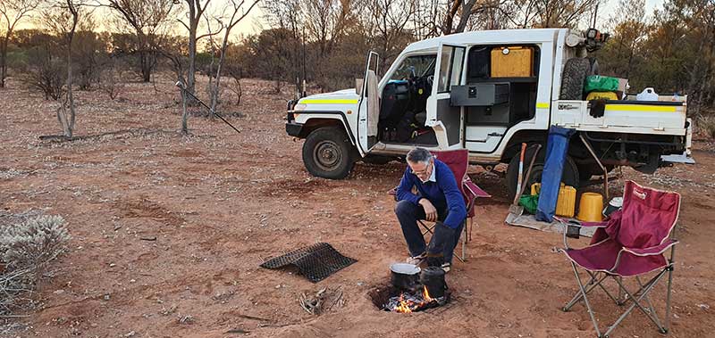
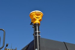
Camp breakfast: The R10 receiver rests on a spur while Phil Richards dines out. (Photo: Trimble)
The case for a new approach
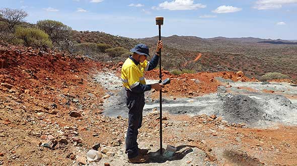
With his aptitude for remote surveying, much of Richards’ project work in WA has been in support of heavily active mining companies. For example, for the past 15 years, one iron ore producer has contracted him to travel more than 600 kilometers from Perth to measure exploratory drill hole collars. Drill collars, the remnants of drilling activity, are 3-millimeter-thick segments of PVC, about 150 mm in diameter, which protrude about 300 mm out of the ground, typically at a 60-degree angle. Measuring the center of that above-surface collar is a crucial stage in the exploration process to enable the client to develop a geological model of the mineral resource underground.
Managing 10 prospect sites across 300 km, the number of drill holes can vary from year to year, but there can be as many as 100 holes spread out over a few prospects at a time. Since 2007, Richards has been using Trimble R8 and, more recently, Trimble R10 GNSS receivers and RTK technology to acquire the drill-collar measurements.
On average, each prospect is 5 km by 2 km and has its own coordinate network. Depending on the number of collars and the distance to each, Richards would set up between two and nine RTK base stations on known control points to set project control. Using his Trimble GNSS receiver, he’d either drive or walk to each drill collar, set the foot of the range pole on the center of the collar at ground level, take a reading and record the measurement in Trimble Access field software on a Trimble TSC3 controller. Although the need for multiple base stations had added hours onto the projects, the RTK method consistently provided the needed accuracy.
X hits the spot
In 2015, the iron ore company restructured its mineral exploration program. Rather than drill numerous exploratory holes across a few prospects, the new focus was to drill fewer holes spread over the entire project area. That was going to be problematic for Richards’ traditional RTK routine.
“Previously, when it was predominantly surveying and less traveling, the RTK approach worked well for the project, even though setting up base stations is time consuming,” said Richards. “But when that switched to less surveying and more traveling, continuing with RTK was going to increase costs because each time I have to set up my base station, that’s an extra hour. If I have 10 drill-collar zones, that’s 10 hours. And if my base station is 10 minutes away, it adds more time and expense if I have a problem with it, or I can’t get a reliable signal, and I have to travel back to it to fix it or move it. The reduced number of collars and the increased distances between them required a more efficient method to make the project profitable.”
Taking the R10 off the vehicle mount. (Photo: Trimble)
Richards decided to test Trimble’s CenterPoint RTX correction service as an alternative. CenterPoint RTX is built on a network of GNSS tracking stations around the world that stream multi-frequency, multi-constellation data to the company’s network control centers. Advanced data processing algorithms analyze the three main error sources: satellite orbits, clock offsets and atmospheric effects, and develop models and correction data. This information is delivered to GNSS rovers via L-band satellite communications. The rover combines the correction data with its own satellite observations to produce accurate positions.
Richards ran five trials in conjunction with varied exploration surveys at test sites across 1,000 km of terrain. He took RTX measurements of survey control points with his R10 and compared them to the same positions acquired with RTK. Although the CenterPoint RTX can take up to 15 minutes to reach sub-2-centimeter horizontal accuracy in WA, Richards said the technology regularly delivered on performance. Most importantly, this technique enabled him to work without a base station and obtain real-time GNSS positions with centimeter accuracy even in isolated WA.
Integrating Trimble’s CenterPoint RTX into his workflows enabled Richard to use a single GNSS receiver system, much like working within the VRS networks available in the more populated areas of Australia.
Into the Outback
For the 2019 campaign, Richards and a colleague were contracted to acquire accurate 3D positions for 13 drill-collar holes stretched across two major prospects about 150 km apart. Their area of interest was 700 km northeast of Perth.
Within a 15-km-wide area, they had to acquire measurements for eight drill-collar holes. They calibrated the R10 receiver to the nearest control point to tie into the site’s coordinate system and moved through the area, methodically recording the positions of each collar hole. Despite the rough terrain, they finished both prospect sites in 1.5 days, compared to 2.5 days had they used RTK.
“Given the project format, with so much travel time and less surveying time, RTX is really the only way to do it,” Richards said. “It’s far quicker than setting up base stations — I saved 50% of the time using RTX on this campaign. I’m more efficient; I’m able to keep costs down; and I have the confidence in the system that I know I’ll deliver on accuracy. It’s hard to justify using any other method.”
The Trimble CenterPoint RTX correction service, enabling centimeter-level absolute positioning around the world without the need for RTK reference-station infrastructure, is now available to many users, including integrators of professional high-precision equipment and consumer products such as in the automotive sector. Access is provided via a software library compatible with any GNSS device. The corrections now contain detailed integrity information for safety-critical applications.
The RTX infrastructure is made up of approximately 120 globally distributed RTX reference stations. Receivers at these stations transmit measurement data at 1 Hz to the RTX server centers, where the correction data is computed. For redundancy purposes, multiple servers in the United States and Europe are operated. A failsafe architecture avoiding any single point of failure in the processing chain has produced a very high availability of corrections. Today the system supports GPS, GLONASS, Galileo, BeiDou and QZSS satellites. It is a multi-frequency system supporting two or more frequencies for each satellite system.
The correction stream is available to users using L-band signals broadcast via geostationary satellites and IP connections. The L-band transmitted RTX data stream uses a bandwidth of 600–2400 baud, and a highly compressed data format with a resolution of 1 millimeter, with an average latency of 8 seconds in L-band mode and 5 seconds in IP mode. The data stream is encrypted via an Advanced Encryption Standard (AES) with a key length of 256 bits to guarantee safe transmission. Data transmission integrity is assured with a 32-bit cyclic redundancy check attached to every message. The RTX correction stream provides information on satellite position, satellite clock, ionospheric and tropospheric models, and code and phase biases.
The orbit determination is done in real time using a reduced dynamic approach with dynamic models and exploiting the accuracy of the phase measurements after ambiguity fixing. Based on the computed orbits, the satellite clocks are estimated at 1 Hz, where integer ambiguity fixing is performed for the different satellite systems.
Next, a single-layer global ionospheric model is computed and represented through spherical harmonics. There are currently two areas with a denser network than the global network; these cover Europe and the mainland U.S. with more than 1,000 base stations. Using these stations, regional ionospheric and tropospheric models are computed, which then provide a fast convergence (RTX-Fast service).
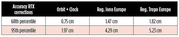
The satellite position and clock information has centimeter accuracy and allows the client to compute precise point positioning (PPP) with carrier-phase ambiguity resolution. Table 1 shows service accuracy.
Table 1. Accuracy of the RTX corrections from more than three years (June 2015–July 2018) of residuals computation in the European RTX-Fast network. (Table data: authors)
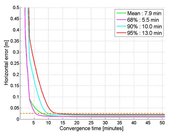
Once the ambiguities are resolved, the position solution is accurate to a few centimeters. The global RTX-Standard service provides convergence times of 7 minutes to 20 centimeters (cm) horizontal error (95%) and to 2.5 cm (95%) in 13 minutes as shown in Figure 2. The regional RTX-Fast service (U.S., Europe) provides convergence times of less than a minute with centimeter accuracy. The warmstart convergence time is approximately 13 seconds.
Figure 2. Global convergence of RTX out of 52 globally distributed stations covering one month of data. (Image: Trimble)
The accuracies specified are achievable with precise Trimble GNSS positioning hardware. For integration into non-Trimble devices, an RTX software library is offered, which gives the user real-time access to the individual data in the RTX correction stream. For use of this library in safety-critical systems such as advanced driving-assisted systems (ADAS) or semi-automated driving, this library was certified to follow the ASIL-B ISO 26262 standard and the automotive ASPICE standard. This library is available for easy integration into third-party applications.
In addition to the real-time RTX solution, a web-based post-processing solution is available for public use free of charge. It is possible to upload static Trimble or RINEX files to the server, post-process the measurement data, and retrieve a precise position in various coordinate frames.
Service integrity is continuously monitored at independent stations from the RTX tracking networks in Europe and the US. The integrity of the service is provided at the correction data domain. The integrity monitoring part of the RTX system minimizes the risk due to events such as unplanned satellite maneuvers or wrong broadcast ephemeris; satellite signal or clock anomalies; ionospheric storms; or problems in transmitting the RTX correction stream.
The monitoring stations compute phase observation residuals (with ambiguity fixing) using the station measurements and the received RTX corrections. These residuals represent the actual errors of the corrections as seen by the monitoring stations at the line-of-sight (Table 1). The thresholds at which corrections are considered as faulty are the following: 0.5 m + QI (quality indicator) for orbit + clock corrections and regional tropospheric models, and 1.0 m + QI for regional ionospheric models.
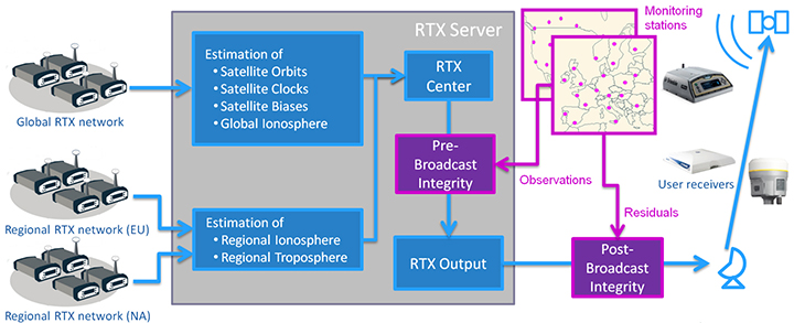
The integrity monitoring consists of two steps (Figure 1): a pre-broadcast check, where potentially faulty corrections are detected and filtered out before leaving the computing server, and a post-broadcast check, where additional errors in the transmission channel are detected and alarms are issued to the users.
Figure 1. Generation and transmission of RTX global and regional corrections, including pre- and post-broadcast integrity monitoring. (Image: Trimble)
Integrity flags and alarms are constantly inserted into the correction stream and output by the RTX client library. The integrity information notifies clients of the presence of integrity monitoring and provides timely alerts in case of detected correction-data integrity violations. The time-to-alert limit goals are 17 seconds for L-band transmission and 13 seconds for IP transmission for the RTX service.
The RTX corrections includes quality indicators. In particular, the quality indicator for the satellite clock includes a “DoNotUse” flag to indicate potential problems with the given satellite. This flag prevents the use of the satellite for positioning when received by the user. The quality indicators of the corrections are indeed a first integrity layer. In 2017 the pre-broadcast integrity monitoring was added to act as a second layer. In 2019, with the addition of the post-broadcast integrity monitoring, a third integrity layer was added to the RTX correction data stream.
The RTX system provides access to centimeter-level corrections allowing centimeter positioning on a global basis. RTX-Fast services are available in Europe and the U.S. with pre- and post-broadcast integrity monitoring currently being deployed.
The authors are engineers with Trimble Terrasat GmbH, Germany.
General Motors (GM) is using Trimble RTX (real-time eXtended) technology as the high-accuracy GNSS/GPS correction source to deliver absolute positioning to vehicles equipped with GM’s Super Cruise hands-free highway driving system, now available on the 2018 Cadillac CT6.
GM customers using Super Cruise featuring Trimble RTX technology can have peace of mind on the road knowing that RTX plays an important role in maintaining lane position for hands-free driving on divided highways.
https://youtu.be/_rxW68ADldI
Super Cruise also uses precision lidar mapping data, a state-of-the-art driver attention system, and a network of camera and radar sensors.
Trimble RTX technology provides real-time, multi-constellation GNSS positioning capable of achieving better than 1.5 inches accuracy. Standard GPS signals can drift up to 25 feet, which could cause incorrect lane identification.
The 2018 Cadillac CT6 features Super Cruise hands-free driving technology for the highway. (Photo: GM)
Lane-level accuracy is a critical enabler in advanced driver assistance systems increasingly being used on highways. When used in conjunction with high-definition maps, cameras, radar and inertial sensors, Trimble RTX improves lane-level positioning performance for semi-autonomous and autonomous vehicles.
Trimble has a long history of pioneering automation and vehicle autonomy to improve productivity — from providing positioning solutions for some of the earliest robotic applications in the 1990s to delivering automated steering for farm tractors, automated blade control for earthmoving equipment and providing advanced positioning technology for fully autonomous trucks.
Trimble is now enabling semi-autonomous operations for passenger vehicles with Trimble RTX technology, delivering high-accuracy GNSS corrections via a global network to support absolute vehicle positioning in combination with other sensors and inertial dead-reckoning.
Trimble’s RTX technology uses signals captured by more than 100 Trimble GNSS reference stations around the globe. Trimble RTX corrects the signals for atmospheric conditions, satellite orbit and time synchronization errors and then sends those signals to GM vehicles with Super Cruise via OnStar 4G LTE cellular.
The Trimble network is supported by redundant servers that are monitored 24/7 by a team of network engineers and IT specialists ensuring optimal signal performance and reliability for drivers who will depend on it.
“Through our collaboration, the combined technologies of GM and Trimble will transform the way the world drives,” said Patricia Boothe, vice president of Trimble’s Advanced Positioning Division. “Trimble RTX is now influencing how we interact with our vehicles and the environment around them — helping to minimize driver fatigue and improve the assisted driving experience.”
For those who want high accuracy, but don’t need it full time, high-productivity dedicated professional solutions may not be cost-justified. In these cases, a “positioning as a service” subscription could offer a viable use model.
Achieving precision positioning with just a standard mobile device, a correction stream using the mobile device’s data connection and a high-accuracy positioning application produces a very low barrier to achieving high accuracy.
ByStuart Riley, Herbert Landau, Victor Gomez, Nataliya Mishukova, Will Lentz and Adam Clare, Trimble Inc.
We expect that for professional applications that need precision positions, a dedicated system that employs a custom GNSS chipset and purpose-built applications will continue to be the right solution. However, it becomes clear that the ubiquity of consumer mobile devices, with increasing computing power, ruggedness and an expanding feature set, presents fertile ground for new development of improved positioning systems that don’t have strict professional requirements.
A range of new use models and applications will be enabled by consumer mobile phones with technology that improves positioning performance. The goal of the work presented here is to assess what level of performance can be achieved by using proprietary PVT (position, velocity, time) engines utilizing GNSS measurements from the Android GNSS measurement application programming interface (API).
We first review GNSS measurement and positioning performance from a subset of the current Android phones/tablets currently on the market. Then we show the position performance achievable using precision engine with measurements from a dual-frequency GNSS chipset targeted for the cellular handset market. This class of device is expected to be integrated into consumer cellular devices on the market within the next 1 to 2 years.
Performance of Current Phones
We tested various devices including the Nexus 9 (which provides phase data) and various other Android devices that implement the new API. Most devices tested do not support phase data; of the few devices tested that do provide phase data, all except the Nexus 9 implement GNSS power duty cycling. This is a mode where the GNSS chipset is only active for a fraction of each second to reduce power consumption. This results in cycle slips each epoch, which makes carrier-phase processing for real-time kinematic (RTK) unusable.
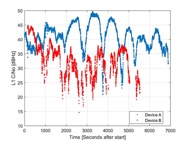
During the testing a wide range of performance across devices was observed. Figure 1 shows the C/NO for a high-elevation GPS satellite collected at the same time from two different Android models that implement the GNSS measurement API. The units were located in a clear environment less than a meter apart. Deep fades are present, most likely caused by deconstructive multipath.
Figure 1. Comparison of the C/NO from two different Android devices.
However, the devices show significantly different tracking performance: device B reports over 10 dB lower C/NO for much of the test and eventually stops reporting measurements. During our analysis, around six different Android devices have been tested; it isn’t clear whether the devices tested are typical over a broader population of device types.
Before attempting to position with observables from Android devices the measurement quality was analyzed. As only a subset of current devices that support the API provide phase information we wanted to evaluate both a phase-based RTK engine and a pseudorange/Doppler based code engine to determine what is possible from each class of device.
One of the devices tested was a Samsung S7 device. It provides pseudorange, Doppler and phase via the GNSS measurement API. However, the phone implements power duty cycling so after a short period of operation the duty cycling mode was enabled which resulted in a cycle slip on the phase every epoch.
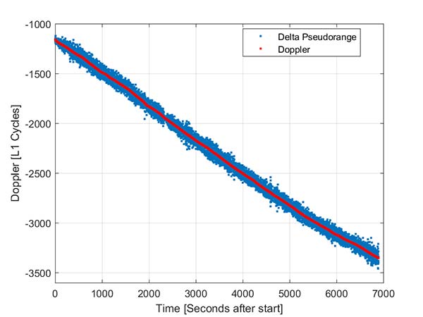
To derive an improved position from this class of device pseudorange and Doppler can be fed into a code-phase positioning engine. Fortunately, the Doppler provided by the device is of reasonable quality as can be seen from Figure 2.
Figure 2. Android GNSS observables: Doppler versus time-differenced pseudorange.
In this simple analysis measurements from a single high elevation satellite were analyzed. The Doppler is plotted along with the differenced pseudorange converted into L1 cycles. It can be seen that as expected the Doppler has much lower noise and so can be used in a pseudorange smoother.
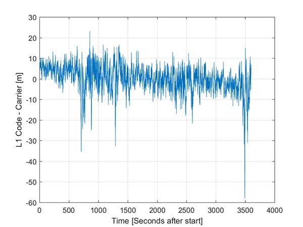
A simple way to view the pseudorange noise is to subtract the carrier phase from the pseudorange. If there are no cycle slips this should show ionospheric divergence with the noise dominated by the pseudorange noise. The absolute level is arbitrary as it includes integer carrier cycles. Figure 3 shows an example from an Android device.
The data was captured on a building roof in an open environment. There’s a slight downward trend due to the ionospheric divergence between code and carrier, but the metric is dominated by the pseudorange noise. For this example from a high elevation GPS satellite the standard deviation is 6.5 meters. For comparison, a precision receiver connected to a precision GNSS antenna providing unsmoothed pseudorange in this environment would have a standard deviation of a few decimeters.
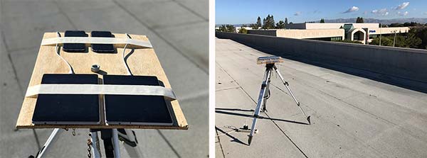
Another way to assess the measurement performance is to form double difference residuals. Data was logged from pairs of identical devices mounted with a common orientation. An RTK system was used to measure the same point on each device. The camera lens location above the screen was used as the reference point.
An accurate vector between the two references points was computed and used as truth in a double-difference residual analysis. Even though we do not know the precise location of the phase center of the antenna, because the difference was performed between two devices that are the same model and have the same orientation the error in the phase center location is common and will cancel. Various pairs of devices were tested by being mounted on a wooden board on a tripod at approximately waist height. The test configuration is shown in Figure 4.
Figure 4. Android device test configuration.
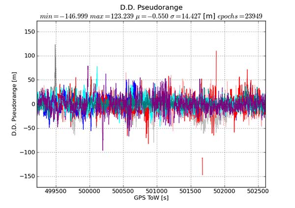
Figure 5 provides the double difference GPS L1 C/A pseudorange residuals between two Android devices. We see errors beyond 100 meters and a standard deviation across all data of 14.4 meters. A precision system (RTK or RTX/PPP) would use a standard survey quality base or network of bases and not an Android device for the correction data.
Figure 5. Short baseline double-difference pseudorange, Android devices.
Consequently in a typical operating mode where a precision data stream provides corrections, the contribution in a double difference from the pseudorange on the Android devices would be roughly half the Android-to-Android residual seen in this test or approximately 7.2 meters for this example.
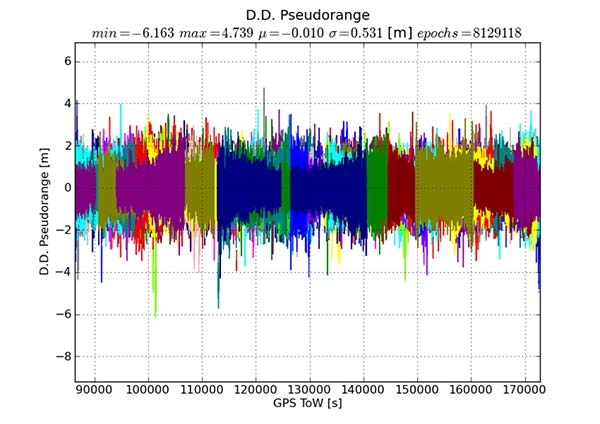
For comparison, the same metric was generated between two precision GNSS units connected to antennas on the same roof. While the data was not from the same time period, we observe very consistent performance over time.
Figure 6 shows the same pseudorange double difference across a short baseline over 24 hours. When comparing Figures 5 and 6, note the difference in the scale on the pseudorange residual axis. The standard deviation from a pair of precision devices is 53 centimeters (cm) or 27 times lower noise than an example pair of Android devices.
Figure 6. Short baseline double-difference pseudorange, precision devices.
All phones that provide GNSS measurements via the Android API publish the phase data in the accumulated delta range field. An accumulated delta range is not necessarily a full phase measurement; it can have an arbitrary starting phase.
For example, in a precision GNSS receiver, if the receiver locks to a satellite and some time later locks a second channel to the same satellite, the phase measurement from the two channels may have a different integer cycle component, but the subcycle component would be the same except for millimetric tracking noise.
If the two channels are providing accumulated delta range the initial phase offset may differ by up to one cycle. From the population of Android devices that publish phase that we have tested we have not observed any devices that deliver true full phase.
They all deliver an accumulated delta range with an arbitrary phase offset. This limits a phase engine to float processing and ambiguity fixing is not possible. The Android phase data collected from the previously described experiment was processed to provide the double difference carrier residuals. This is shown in Figure 7.
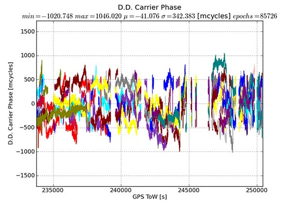
Figure 7. Short baseline double-difference phase residuals, Android devices.
The y-axis is in millicycles (1,000 millicycles = 1 cycle or approximately 19 cm for L1 GPS). Jumps are seen as the reference satellite changes or when the measurements have cycle slips. In this case the standard deviation is 342 millicycles. A double difference residual on a precision receiver in a similar environment with a high-quality antenna on a short baseline is an order of magnitude lower than this.
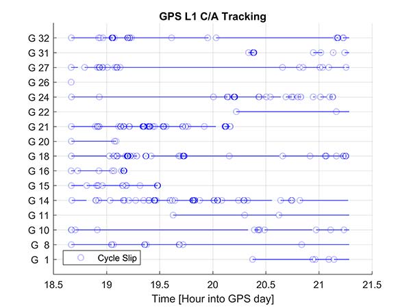
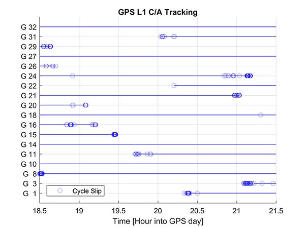
Another useful metric to review are the number of reported cycle slips. Figures 8 and 9 show a comparison of the cycle slips reported on GPS L1 C/A from an Android device compared to data logged on a precision receiver over the same time span. The receiver tends to only cycle slip at low elevation; the device had a zero-degree mask. The Android GNSS device cycle slips at higher elevations, probably a result of deep multipath fades due to the poorer antenna.
Figure 8. Cycle slips, Android device.
Figure 9. Cycle slips, precision device.
In an ION GNSS+ 2017 paper, we showed the achievable position performance using an RTK engine that had been previously customized to operate with measurements from consumer GNSS chipsets. It operated in a float mode due to the sub-cycle issue found in phase data from Android devices.
We also demonstrated the performance from a precision code-based PVT engine that had changes to the a priori measurement error estimate, a modified pseudorange/Doppler Hatch filter and used SBAS data to correct the position. As very few current Android devices deliver phase information the two engines were used to analyze what is possible today with the pseudorange and may be available in the future as phase is more universally available.
Data was processed from a Nexus 9 tablet, the only known Android device that has GNSS power duty cycling disabled. The unit was unmodified and so the Android tablet’s integrated GNSS antennas were used. The 2D performance is given in Table 1.
Table 1. 2D performance from Nexus 9 Android tablet.
Only GPS L1 and GLONASS L1 measurements were used and the RTK float solution delivered similar performance to the pseudorange solution. This is due to a combination of issues, very high pseudorange noise, and a significant number of cycle slips (see Figures 5 and 8). Only single frequency data was available, and while the engines used had been tuned for consumer data, they were not specifically designed for this class of data.
Next-Generation Phones
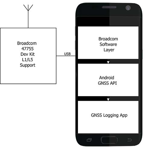
Within the next couple of years improved chipsets are expected to be available to consumers that will result in improvements in achievable positioning performance. In May 2017, Broadcom provided us with a development kit for its next generation L1/L5 multi-system BCM47755 GNSS chipset. This allowed us to assess what may be possible when improved GNSS chipsets are integrated in the next generation of cellular devices.
Figure 10. Broadcom BCM47755 development system.
The development environment included the GNSS chipset with an external antenna port so both a cell-phone equivalent antenna and a precision antenna could be compared. This allowed us to evaluate the impact of the antenna performance on the GNSS observables and positioning results. The Broadcom GNSS development system communicates via USB to a Samsung S7 phone and publishes data via the Android GNSS measurement API so the equivalent data flow of an integrated cellular device is maintained (see Figure 10).
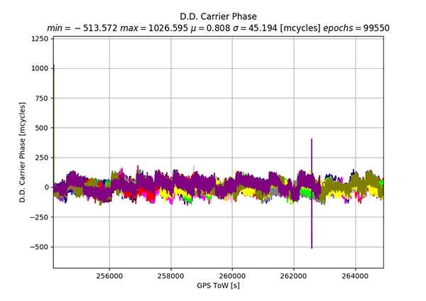
In our ION paper, we showed the typical phase double-difference residuals observed from current Android devices. The Broadcom BCM47755 originally provided similar performance, although it also supports GPS L5 and Galileo E5A. In November 2017, Broadcom provided a firmware update that resolved the sub-cycle phase issues. With the updated Broadcom software, the double difference carrier residuals for GPS L1 on a zero baseline when differencing a precision receiver to a Broadcom BCM47755 are shown in Figure 11.
Figure 11. Precision GNSS to Broadcom BCM47755 zero baseline double difference carrier-phase residuals.
The standard deviation is 45 millicycles which is approximately 8.6 millimeters (mm). This is substantially better than earlier implementations of the Android GNSS interface (see Figure 7) and sufficient to perform RTK ambiguity resolution.
The rest of the results in this article were obtained with the improved firmware along with a new precision position engine. This engine was designed from inception to support GNSS measurements with differing quality and so can more optimally process the Android GNSS data. The effect of the improvements to the Broadcom firmware and the change in the processing engine can be seen if the results in our ION paper are compared to the data in this section.
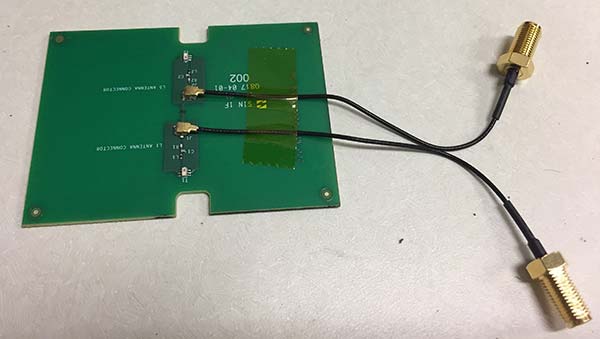
To attempt to model what may be possible with a phone based on a next-generation chipset, a cell-phone equivalent antenna provided by Broadcom was used in some of the tests with the development system, as shown in Figure 12. This device has separate feeds for L1 and L5.
Figure 12. Cellular equivalent antenna.
Datasets were collected with the multi-frequency GNSS BCM47755 device. The data was captured in the Android GNSS measurement API format and converted to proprietary format files for further processing. All data was collected in Sunnyvale, California.
Measurements from GPS L1/L5, Galileo L1/E5A, GLONASS L1 and BeiDou B1 were logged and analyzed. The Precise Positioning Engine (PPE) allows performing carrier-phase RTX and RTK and a pseudorange-based solution using the RTX corrections. Tests were performed by using a precision antenna and a cell-phone equivalent GNSS antenna.
With Precision GNSS Antenna
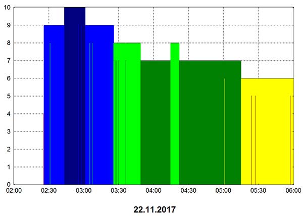
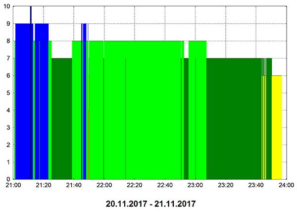
These datasets were collected on a zero baseline with a precision receiver to allow a direct comparison of results with a professional receiver. The first test was on Nov. 22, 2017, where the Broadcom GNSS chip and the receiver were connected to the same professional antenna.
As seen in Figure 13, both GNSS receivers provide centimeter-level accuracies after some convergence time. With the current satellite constellations, only a third of the GPS satellites have L5 and only about half of the E5-capable Galileo constellation is in space. During this 3.5-hour test, the number of dual-frequency measurements processed by the engine that used the Broadcom chipset — data that does not support L2 — ranged between 6 and 10 satellites (Figure 14).
Figure 13. RTK performance for a 3.5-hour dataset sampled on Nov 22. Broadcom chip at left and precision chip at right. A short baseline was used — precision antenna.
Figure 14. Number of GPS L1/L5 plus Galileo E1/E5A dual-frequency measurements used by the position solution based on the Broadcom chipset — precision antenna.
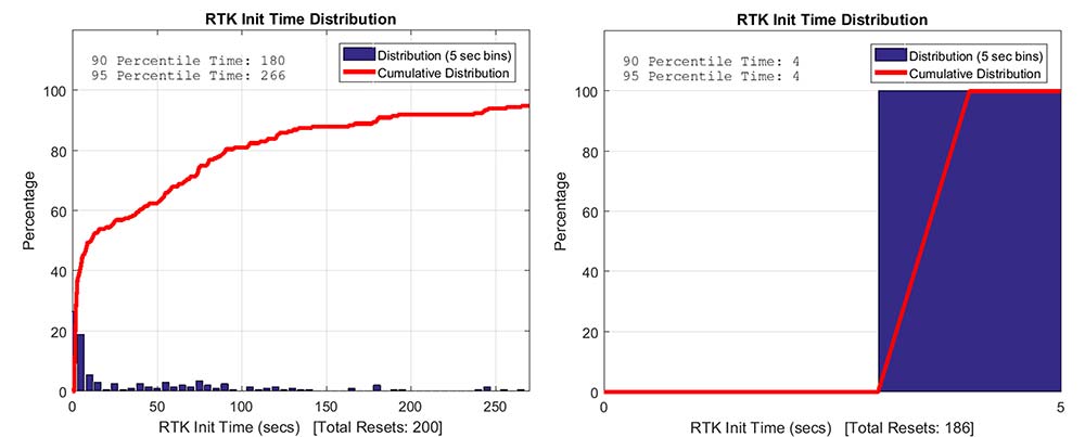
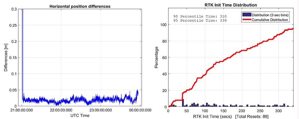
Convergence times were measured with post-processing tools by splitting the datasets into individual time spans. Figure 15 shows that the consumer GNSS chipset is able to get fixed ambiguity solutions but it takes considerably more time (266 seconds versus 4 seconds) for the 95% of initializations. However, the system is fixing ambiguities and provides centimeter level positioning.
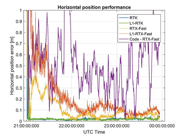
The same datasets were also processed with RTX-Fast in California. Thus the base station data was replaced by a global/regional correction stream received from an internet-based data source (Figure 16).
Figure 15. RTK initialization performance, dataset sampled on Nov 22. Broadcom chip at left and precision receiver at right — precision antenna.
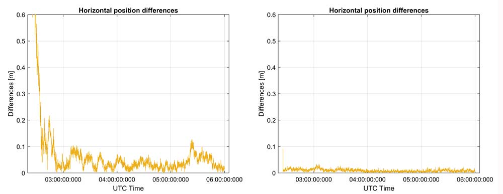
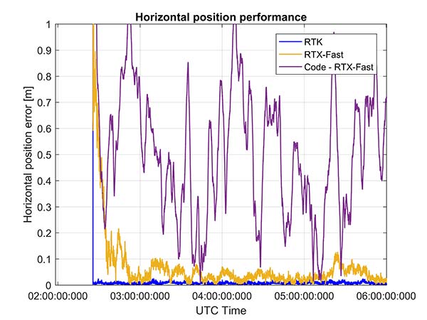
Figure 16. RTX performance for a 3.5 hour dataset sampled on Nov. 22 (Broadcom chip at left and Trimble chip at right) — precision antenna.
Horizontal accuracy for Broadcom reach 10 cm while the precision receiver reaches better than 3 cm. The degradation is in part due to the difference in quality of the carrier phase and the different number of dual frequency satellites processed. Precision devices provide measurements on E1/L1, L2 and L5/E5 providing at least dual frequency data from GPS, GLONASS, Galileo, BeiDou and QZSS.
The Broadcom chipset tested provided dual frequency GPS and Galileo along with single-frequency GLONASS and BeiDou; however, due to limited BeiDou constellation visible in California, data from this constellation was not used.
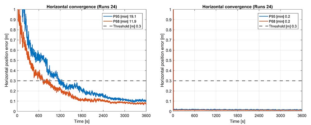
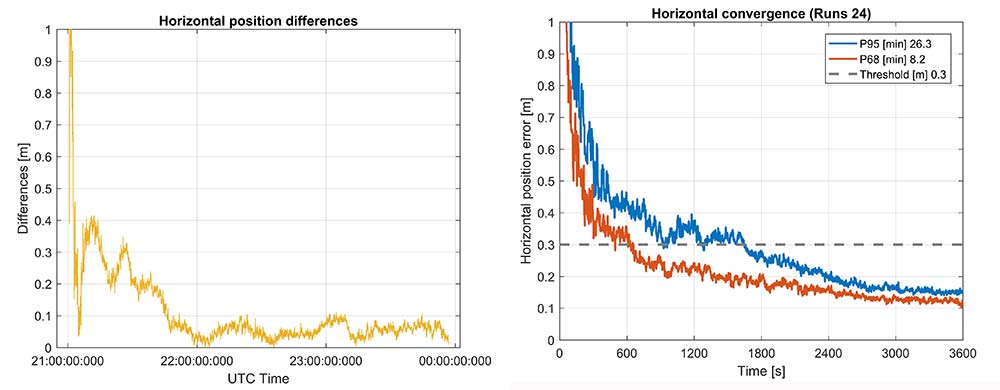
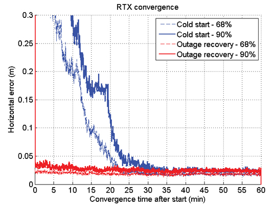
Convergence was also analyzed and is shown in Figure 17. From the data, we generated 24 convergence runs by taking one hour, progressively shifting the start time by 5 minutes and running the data with different start times through the PPE engine. This produced 24 runs, which were translated into 68% and 95% convergence statics shown.
Figure 17. RTX convergence performance for a 3.5-hour dataset sampled on Nov. 22. Broadcom chip at left and precision chip at right — precision antenna.
Figure 18. Code RTX performance for 3.5-hour dataset sampled Nov. 22 and corresponding RTK and RTX phase solutions — precision antenna.
The RTX-Fast solution for Broadcom reaches 30 cm horizontal error in 68% of the cases in approximately 12 minutes. The RTX-Fast convergence using precision GNSS data is near instantaneous as can be seen in the right of Figures 16 and 17, reaching centimeter accuracy.
The code position solution using the RTX correction stream provides sub-meter positioning (Figure 18).
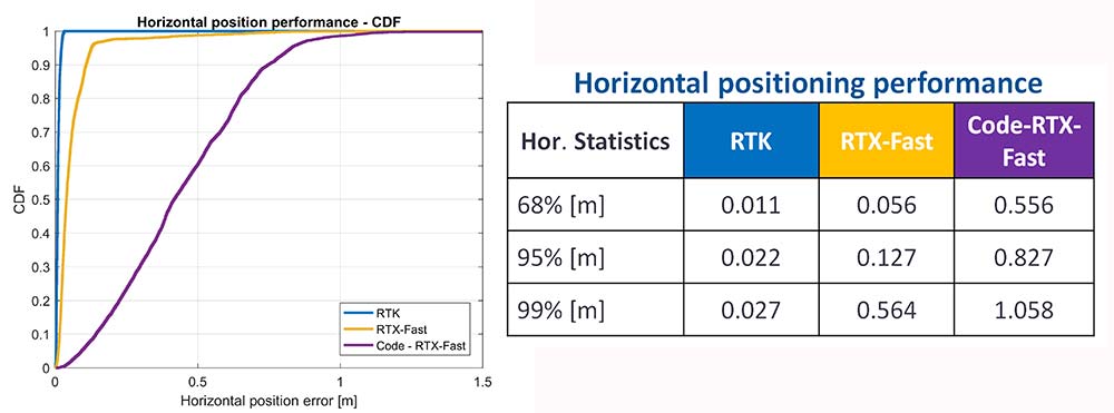
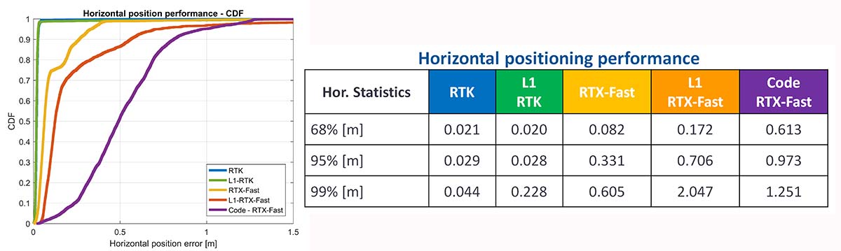
As a summary, the cumulative distribution function plots (Figure 19) show the performance differences for this static environment, on Nov. 22.
Figure 19. CDF plots for the different PPE position solutions — precision antenna.
Cell-Phone GNSS Antenna Results
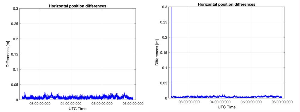
Similar tests were performed using an external cell-phone GNSS antenna, which is close to the antenna used in a typical smartphone. RTK performance shows centimeter-level accuracies and reasonable convergence times, which are slightly worse than the results with the professional antenna (Figures 20–24).
Figure 20. RTK positioning and initialization performance for the Broadcom chip and the cell antenna sampled on Nov 20 — cell-phone GNSS antenna.
Figure 21. RTX-Fast positioning and convergence performance for the Broadcom chip and the cell antenna sampled on Nov. 20 — cell-phone GNSS antenna.
In general as expected we achieve worse performance when connected to the GNSS cell-phone antenna for all the different positioning modes. For the cell antenna we also generated single-frequency RTK and single-frequency RTX-Fast position solutions and compare it with a code positioning solution.
Positioning Engine in Android
Figure 22. Number of GPS L1/L5 plus Galileo E1/E5A dual-frequency measurements used by the position solution based on the Broadcom chipset — cell-phone GNSS antenna.
The results presented in this article captured GNSS data using the Android API and then post-processed the data using PC versions of the position engines. A significant amount of data has been captured and analyzed using this method.
For the purpose of real-world demonstration the PPE has been implemented in an Android app to be used in cell phone devices. This PPE is able to provide RTK, RTX and code based positioning technology in one single PPE library.
The app has been tested running on a Samsung S7 connected to Broadcom’s new chipset development kit as well as a Nexus 9 tablet that uses an older generation GNSS chipset.
Figure 23. Code RTX performance, the dataset sampled Nov. 20 and corresponding RTK and RTX phase solutions — cell-phone GNSS antenna.
Future work will refine this solution as well as evaluate how well the system works when mobile. The data collected in this article operated in an environment with a clear view of the sky. We plan to characterize what happens when the platform moves with both pedestrian and automotive dynamics, as well as the effects of body masking and challenges with changes to the GNSS antenna reception pattern when the phone is held.
Summary
While this article has highlighted that sub-meter and centimeter accuracy have been achieved in a laboratory environment, there are many challenges to be addressed before centimeter accuracy in a phone can be achieved with performance suitable for users in real-world environments.
Figure 24. CDF plots for the different PPE position solutions for cell antenna dataset.
The challenges include very high multipath, significant differences in the tracking performance between different devices, and high rates of cycle slips. As very few Android-based devices provide continuous phase, a pseudorange/Doppler-based engine has been modified to accept Android data.
Based on the testing with existing devices it is possible to achieve position solutions of 1–2-meter accuracy in ideal static scenarios. This is a significant improvement in accuracy for Android based devices.
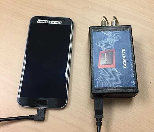
Figure 25. PPE engine on a Samsung S7 with a Broadcom BCM4775 evaluation kit.
However, as performance differences were observed between different mobile devices significantly more data needs to be collected over a larger set of devices to review the repeatability of these preliminary results from existing Android devices.
The Broadcom BCM47755 development kit for a dual-frequency GNSS chipset intended for future phones has allowed us to review the potential position performance that may be achievable in a handset in a few years.
By connecting this next-generation GNSS chipset to a GNSS antenna typical of a cellular device and comparing the performance from a precision GNSS antenna, we’ve shown for the first time that it is possible to produce precision positions from a static cellular class GNSS device in ideal conditions at the centimeter level with both an RTK solution and a PPP solution.
However, due to the significantly higher measurement noise and high multipath from the cellular device’s GNSS antenna, the convergence times to reach centimeter level remain a challenge; although using dual-frequency phase data from a cellular GNSS chipset with a PPE and RTX service, the position is very rapidly sub-meter.
Future work will focus on analyzing how the performance changes when operating in the normal user environment. The effects on the measurements of user motion, body masking and de-tuning of the antenna when the device is held need to be quantified. The Nexus 9 tablet used in this article does not have integrated cellular. The Broadcom development kit connects to the phone via a cable and is also not integrated into the handset.
We will be evaluating what may happen with a more integrated unit to make sure emissions from devices with integrated cellular very close to the GNSS antenna do not result in further degradation.
As the position performance is very sensitive to the quality of the antenna from both multipath and cycle slips due to low C/NO and deep fades, we’ll also evaluate how well the performance of the PCB-based GNSS antenna, which is part of the BCM47755 evaluation kit, matches current handsets.
Acknowledgment
This article further develops work first shown in an ION GNSS+ 2017 paper, “On the Path to Precision — Observations with Android GNSS Observables.”
Manufacturers
Trimble CenterPoint RTX is the satellite orbit and clock corrections service used here, enabling a PPP-like positioning with ambiguity fixing, providing better than 4 cm with typically less than 10 minutes’ convergence.
RTX-Fast functionality in Europe and parts of California uses regional atmospheric models to provide better than 4-cm horizontal in typically less than one minute. When precision and professional receivers and RTK engines are mentioned in this article, they are Trimble devices, the BD940 receiver in some cases.
A Trimble Zephyr 3 antenna was used in many tests shown here.
The 2014 Trimble Dimensions User Conference is being held in Las Vegas this week. Photo: Trimble
With more than 4,000 attendees, this year’s Trimble Dimensions User Conference was the largest ever and, I must say, a well-organized event chock full of technical content — enough to squelch the most intense geospatial hunger pangs you might have.
One could write a book on all the technology and market segments that Trimble is pursuing and offering solutions for. In addition to a wide range of GNSS, geospatial, construction, control, and data management systems previously offered, Trimble boasted a USB stick full of press releases with new product and service announced at Dimensions. So, the challenge is deciding what to write about without writing a little bit about everything.
After my first day at Dimensions, it became clear to me what I needed to do. Among the many product and service announcements was a new GNSS correction service named Viewpoint RTX. While I’ve tried to stay up to speed on Trimble’s various GNSS real-time correction services, this one was the straw that broke the camel’s back for me. I decided I needed to get a solid grip on the range of real-time GNSS correction services that Trimble offers because the picture was getting fuzzier, at least to me, with each new real-time correction service introduced. It used to be pretty simple to decipher; not so much any longer. So I had a conversation with Patty Boothe, general manager of Positioning Services at Trimble. Patty, a 15-year Trimble veteran, was appointed GM of the newly formed group three years ago. Here’s the low-down on the services.
Remember, Trimble acquired the land portion of OmniSTAR’s business a few years ago. For years, OmniSTAR has been one of the two dominant commercial satellite-based, real-time GNSS correction services (the other being John Deere’s Starfire service, as well as new entrant Terrastar). The OmniSTAR acquisition was Trimble’s entry into the satellite-based, real-time GNSS correction services business. Since then, Trimble has introduced the RTX (not to be confused with RTK) range of GNSS correction services. You might say that OmniSTAR and RTX are competitive services within Trimble. They are, to a certain extent, and I’ll attempt to clarify that below.
Following is a list of Trimble’s real-time GNSS correction services, starting with the OmniSTAR services:
OmniSTAR VBS: Satellite-based, real-time submeter service. The VBS service has been made obsolete largely by free public satellite-based augmentation systems (SBAS) such as WAAS/EGNOS/MSAS/GAGAN/SDCM. It is still used in geographic regions where free public SBAS don’t exist, primarily South America, Central and Southern Africa, and Australia. GPS-only service. Requires single-frequency receiver (L1).
OmniSTAR XP: Satellite-based, real-time 15-cm service based on Jet Propulsion Lab (JPL) technology and delivered to users on the ground via OmniSTAR’s geosynchronous satellite network. GPS-only service. Requires dual frequency (L1 and L2).
OmniSTAR HP: Satellite-based, real-time 10-cm service based on OmniSTAR’s reference station network and delivered to users on the ground via OmniSTAR’s geosynchronous satellite network. GPS-only service. Requires dual frequency (L1 and L2).
OmniSTAR G2: Satellite-based, real-time 10-cm service based on Jet Propulsion Lab (JPL) technology and delivered to users on the ground via OmniSTAR’s geosynchronous satellite network. GPS+GLONASS service. Requires dual frequency, dual constellation (L1 and L2).
To use OmniSTAR services, one must have an OmniSTAR-enabled GNSS receiver. There are a several receiver manufacturers that support OmniSTAR GNSS correction services, such as NovAtel and Hemisphere GNSS, in addition to Trimble.
After, or at nearly the same time, Trimble acquired OmniSTAR, the company launched its RTX GNSS correction service. RTX’s infrastructure consists of ~110 GNSS reference stations around the world working to create high-precision corrections on a near global scale. The first significant differentiator is that Trimble RTX services are only offered on Trimble GNSS receivers, so you’ve got to be “all in” with Trimble to utilize RTX.
Viewpoint RTX: Internet-based (notice I didn’t write satellite-based), real-time submeter service. This is a new service introduced this week at Dimensions for the new Leap GNSS receiver and the Geo7 GNSS handheld. GPS+GLONASS service. Requires single-frequency receiver (L1).
The above are the three RTX services. There are some options for the above, but let’s talk about satellite-based GNSS correction services for a minute.
The advantage of satellite correction services is that, because GNSS corrections are delivered via satellite, your receiver doesn’t need to be connected to the Internet or have any other sort of terrestrial radio communications to receive data from the GNSS reference station(s). Because delivery is by satellite, you could be in the middle of a desert with no mobile phone coverage within 100 km, and you could still use OmniSTAR or RTX services. The only requirement is that your receiver needs to have direct, continuous line-of-sight to the OmniSTAR/RTX geosynchronous satellite (both services use the same geosynchronous satellites to broadcast the corrections).
The primary disadvantage of OmniStar and RTX services is the “convergence” time required to achieve the stated accuracy service levels. With the exception of OmniSTAR VBS (sub-meter), Viewpoint RTX (sub-meter) and Rangepoint RTX (50-cm) services, the OmniSTAR and RTX centimeter and decimeter services require tens of minutes of initialization time to converge to the stated accuracy. For example, if you want to use the 4-cm Centerpoint RTX service, you may have wait up to 30 minutes for it to converge to 4-cm accuracy.
Now, there are a couple of ways to reduce the convergence time:
Start on a known point. For example, if you’re using Centerpoint RTX on a tractor for planting and you shut down for the evening, you can start it up the next morning (assuming you didn’t move the tractor), and it will converge nearly immediately.
Trimble offers a fast convergence option ($) in some geographic areas where it augments RTX with local RTK reference stations. Currently, Trimble offers this service in five U.S. “corn belt” states.
For OmniStar XP, HP and G2 services, the only way to reduce convergence time is number one above, start on a known point.
It’s important to note that all of the centimeter and decimenter satellite-based services described above are based on real-time Precise Point Positioning (PPP) technology, which is different than RTK technology. The fundamental difference is that real-time PPP technology relies on a global, distributed network of reference stations. For example, Trimble has ~110 reference stations to cover the globe (mostly) with its RTX service. On the other hand, RTK requires a much more dense network of GNSS reference stations. For example, in Washington State there are ~100 GNSS reference stations that comprise the state-wide RTK network.
Lastly, Trimble offers a hybird RTK/RTX service called XFill. The idea is that for RTK users who lose communications to their RTK base or RTK network can use the Centerpoint RTX as a “seamless” back-up, maintaining RTK-level accuracy (1-2cm) for the first five minutes of RTX service, and then degrading to Centerpoint RTX accuracy after 20 minutes. Trimble reports there is no convergence time when transitioning from RTK to RTX, like you would if you were starting RTX right away. Standard XFill is included with certain Trimble RTK receivers and allows up to five minutes of RTX satellite time. Last month at the INTERGEO conference, Trimble introduced Expanded XFill which is a subscription service for those users who want more than five minutes of RTX time. For those users, Patty said that users can buy blocks of RTX time starting at 10 hours.
So, you might ask how Trimble handles the horizontal datum differences between RTK and RTX since they are likely not referenced to the same horizontal datum. For example, in the US, Trimble VRS RTK infrastructure is typically referenced to NAD83/2011 while Trimble RTX is referenced to ITRF08. There’s about 1 meter difference between the two. After finding the correct Trimble person, he said that Trimble does a 3-parameter local shift (dX, dY, dZ) on the fly when in RTK mode so that when there’s a transition from RTK to RTX, the horizontal datum difference is already resolved.
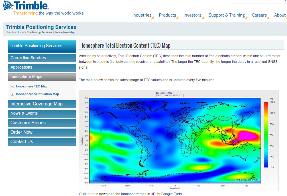
A by-product of Trimble’s ~110 global GNSS reference station network is a real-time, world-wide TEC (Total Electron Content) map. Since real-time PPP GNSS correction services (and public SBAS like WAAS/EGNOS/MSAS/GAGAN) rely on accurate models of the TEC in the ionosphere to account for the GNSS measurement delay, real-time TEC maps give users an indication of how the ionosphere’s TEC is behaving. This sort of map is particularly useful in attempting to predict the understand single frequency receivers using services such as public SBAS, OmniStar VBS, and Viewpoint RTX. The next time you here about an impending solar storm, take a look a the map using this link and see the TEC hotspots around the globe. Notice the more intense activity near the geomagnetic equator.
TEC map from Trimble’s ~110 global GNSS receivers. Photo: Trimble
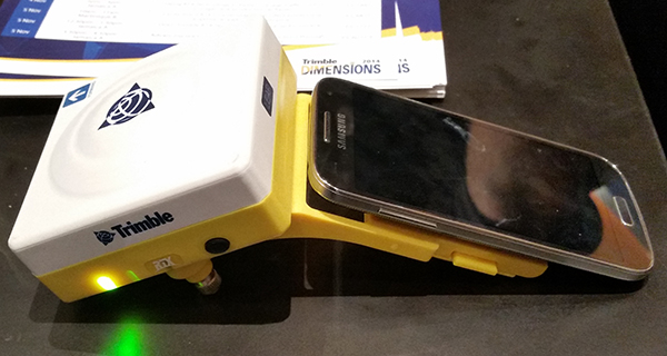
Shifting gears slightly, at the conference, Trimble also introduced a new mobile phone GNSS add-in product called Leap, which uses the Viewpoint RTX service.
Trimble Leap GNSS Receiver with a Samsung Galaxy Phone. Photo: Trimble
Applanix, a mobile mapping and positioning company, is making the Trimble CenterPoint RTX correction service available across its entire airborne mapping portfolio. Applanix is a Trimble Company.
Using the Trimble CenterPoint RTX correction service, Applanix will be able to deliver these benefits to the aerial survey marketplace:
High accuracy — better than 10 cm RMS horizontal after convergence
Speed and low cost — no need for setting up base stations, no need to wait for delivery of public-domain ephemeris data
Simplicity — deal directly with Trimble (no third-party involvement)
More uptime and reliability — use Trimble’s professionally managed, highly maintained private network
Ease of use — there is no additional hardware to purchase, integrate or maintain
Fast and reliable convergence — 30 minutes or less to full accuracy
The announcement was made at Trimble’s China Dimensions User Conference. The CenterPoint RTX service for Applanix airborne mapping products is expected to be available in the fourth quarter of 2013.
“The Applanix aerial mapping portfolio is trusted throughout the aerial mapping community to provide highly accurate position and orientation information for directly georeferencing camera and sensor data,” said Joe Hutton, Director of Airborne Products at Applanix. “By integrating the Trimble CenterPoint RTX correction service, we are maintaining our position at the forefront of accuracy, robustness, and high efficiency in airborne mapping. The CenterPoint RTX correction service gives Applanix products the ability to achieve accuracy required for many types of mapping projects in real time and post-mission, all without the need for base stations – an industry first.”
Trimble CenterPoint RTX correction service is a GPS, GLONASS and QZSS enabled correction service built on Trimble RTX technology. It provides high-accuracy GNSS positioning without the use of traditional reference station-based differential RTK infrastructure.
The solution is also compatible with the Applanix POSPac software to achieve the same level of orientation accuracy as when using base stations, all without the need to have an Internet connection or wait for precise ephemeris data to be available.
Trimble has expanded coverage of its satellite-delivered Trimble RTX technology for surveyors to most of the world. Trimble has also introduced post-processing capability for its CenterPoint RTX positioning service for farmers. Both announcements were made at the Trimble Dimensions 2012 conference being held in Las Vegas this week.
RTX technology enables Trimble xFill, a new technique in RTK and VRS surveying that allows surveyors to continue working in the event the primary RTK or VRS correction stream is not available.
Trimble RTX technology, first introduced in 2011, combines real-time data and positioning algorithms to deliver centimeter accuracy around the world. While RTX technology is available worldwide via IP and cellular delivery methods, Trimble RTX has been available via satellite L-Band only in North and South America. Now, the expanded satellite coverage includes most of Europe, Russia, and the Commonwealth of Independent States (CIS), Africa, Asia, and Australasia.
Powered by Trimble RTX technology, Trimble xFill, a feature integrated into the new Trimble R10 GNSS Receiver, enables a new and innovative technique in RTK surveying, according to Trimble. It seamlessly “fills in” for RTK or VRS corrections for up to five minutes in the event of a temporary connection outage with the primary correction source. Minimizing downtime, Trimble xFill enables higher productivity for field survey crews, allowing them to continue working until radio or cellular connectivity is restored, Trimble said.
“The expanded coverage of satellite-delivered Trimble RTX technology further extends our commitment to providing different ways of realizing high accuracy positioning solutions,” said Patricia Boothe, general manager of Trimble’s Positioning Services Division. “The power of RTX is proven. Trimble RTX is the backbone of Trimble’s latest positioning innovations including the Trimble CenterPoint RTX service for farmers, the Trimble Pivot RTX App, and Trimble Pivot RTX-PP App infrastructure solutions and now, the Trimble xFill feature for surveyors.”
Trimble xFill feature allows satellite corrections to be delivered directly to the receiver with no need for additional equipment such as radios and antennas. With its built-in capability, the Trimble R10 automatically tracks these corrections and will use them when needed. Trimble xFill across the expanded satellite coverage area is expected to be available by late November 2012.
CenterPoint RTX Positioning Services. Enabled by Trimble RTX technology, CenterPoint RTX provides centimeter level positions in real time via satellite L-band and IP/cellular. The new post-processing capability delivers better than one-centimeter accuracy and is available worldwide.
Trimble CenterPoint RTX post-processing is a cloud-based service accessed through www.TrimbleRTX.com, allowing users around the globe to upload static GNSS observation data and receive positioning corrections calculated in the well-defined ITRF 2008 reference frame. The post-processed solution can be transformed to a variety of regional reference frames by selecting a coordinate system and tectonic plate.
“With the introduction of post-processing capability to the CenterPoint RTX portfolio, we continue to extend the breadth of the service,” said Patricia Boothe, general manager of Trimble’s Positioning Services Division. “CenterPoint RTX post-processing gives geospatial professionals another tool for their toolbox, utilizing Trimble’s globally available RTX technology to enable higher-accuracy positioning solutions.”
The open service allows any user to post process 10 data sessions per month.
A new method brings together advantages of real-time kinematic (RTK) and precise point positioning (PPP) in a technique that does not require local reference stations, while still providing the the high productivity and accuracy of RTK systems with the extended coverage area of solutions based on global satellite corrections. The real-time centimeter-level accuracy without reference-station infrastructure is suitable for many market segments — and is applicable to multi-GNSS constellations.
By Rodrigo Leandro, Herbert Landau, Markus Nitschke, Markus Glocker, Stephan Seeger, Xiaoming Chen, Alois Deking, Mohamed Ben Tahar, Feipeng Zhang, Kendall Ferguson, Ralf Stolz, Nick Talbot, Gang Lu, Timo Allison, Markus Brandl, Victor Gomez, Wei Cao, and Adrian Kipka
Real-Time eXtended (RTX) positioning is a technology produced by combining a variety of innovative techniques, which together provide users with centimeter-level real-time position accuracy anywhere on or near the Earth’s surface. This new technique is based on the generation and delivery of precise satellite corrections (that is, orbit, clocks, and others) on a global scale, either through a satellite link or the Internet. The innovative aspects of the new solution can be divided into different categories, which directly relate to the areas that have previously limited the provision of global high-accuracy positioning:
Because of various new aspects of the technique, RTX differs from both differential RTK and precise point positioning as currently understood by the general GNSS community.
System Overview
RTX technology is used to provide centimeter-level GNSS positioning through the CenterPoint RTX service. Figure 1 shows the general infrastructure of the system.
Data from monitoring stations distributed around the globe are collected and transmitted via the Internet to operation centers at different locations. The complete operation centers (enclosed by the red dashed square) are redundant in order to assure the very high (~100 percent) availability of the system. In case it is needed, the correction stream source might change between operation centers and/or processing servers within centers. These operational changes are handled in a deterministic way by all parts of the system including the user receiver. Inside the operation centers, redundant communication servers relay the network observation data to the data processing servers, which host the network processors that produce precise orbit, clock, and observation biases valid for any place on the globe.
After being generated, the precise satellite data are compressed in messages compliant with the CMRx format, specially developed for compact transmission of satellite information. The messages are finally routed to either a satellite uplink station or made available for Internet connection access by the users.
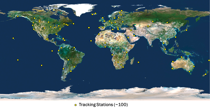
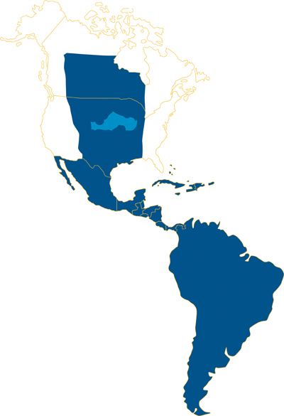
The CenterPoint RTX tracking network currently consists of around 100 stations, distributed across the globe, as shown in Figure 2. The CenterPoint RTX service is currently offered in North and South America, via satellite link, as indicated in Figure 3. Today the CenterPoint RTX service has been made available globally for all those with Internet access.
FIGURE 2. CenterPoint RTX tracking network distribution. (Click to enlarge.)
FIGURE 3. CenterPoint RTX L-band satellite service coverage in the Western hemisphere.
Limiting Factors
To understand the limiting factors associated with global high-accuracy positioning, it is helpful to consider the simplified basic GNSS observation equations for carrier-phase and code measurements:
Φi=ρ+c(dT−dt)+T−Ii+λi Ni,
+Ai−ai+λi(WΦ−wΦ)+BΦ,i−bΦ,i+MΦ,i+nΦ,i
and
Pi=ρ+c(dT−dt)+T+Ii,
+Ai−ai+BP,i−bP,i+MP,i+nP,i
where:
Φi is the carrier-phase measurement for frequency i in meters;
ρ is the geometric distance between the antennas of the receiver and satellite in meters;
c is the speed of light constant in meters per second;
dT is the receiver clock error in seconds;
dt is the satellite clock error in meters per second;
T is the slant neutral atmosphere delay in meters;
Ii is the ionospheric delay for frequency i in meters;
λi is the carrier-phase wavelength for frequency i in meters;
Ni is the integer carrier-phase ambiguity for frequency i in cycles;
Ai is the combined receiver antenna offset and directional variation correction for frequency i in meters;
ai is the combined satellite antenna offset and directional variation correction for frequency i in meters;
WΦ is the receiver antenna phase wind-up effect, in cycles;
wΦ is the satellite antenna phase wind-up effect, in cycles;
BΦ,i is the carrier-phase receiver bias for frequency i in meters;
bΦ,i is the carrier-phase satellite bias for frequency i in meters;
MΦ,i is the carrier-phase multipath for frequency i in meters;
nΦ,i is the carrier-phase observation noise and other un-modeled effects for frequency i in meters;
Pi is the pseudorange measurement for frequency i in meters;
BP,i is the pseudorange receiver bias for frequency i in meters;
bP,i is the pseudorange satellite bias for frequency i in meters;
MP,i is the pseudorange multipath for frequency i in meters;
nP,i is the pseudorange observation noise and other un-modeled effects for frequency i in meters.
The feasibility of high-accuracy absolute positioning relies on the assumption that phase and code measurements on the different frequencies or on specific observation combinations are modeled quite reliably. This ultimately means that the parameters (or certain combination of them) of the two equations given are known very precisely, that is, with an accuracy of better than a few centimeters.
Having a global system where every component of the un-differenced GNSS observational model is well known requires advanced understanding and modeling of the involved GNSS-related effects. This is a general achievement of the RTX system.
(An extensive section here, encompassing satellite orbits and clocks, receiver clock error, antenna phase center odeling, phase wind-up effects, neutral atmosphere delay, and ionospheric delay, appears in the online version of this article, at env-gpsworld-integration.kinsta.cloud/rtx.)
Real-Time Network Processing
As previously stated, the RTX system works based on precise satellite information generated at processing centers and broadcast to users. The precise information employed by the systems comprises satellite orbits, satellite clocks, satellite biases, and other auxiliary information.
The requirements for the satellite orbits to be used in the global RTX system can be summarized as accuracy, continuity, robustness, and reliability. The satellite positions have to be accurate for obvious reasons, including the fact that orbit errors have direct impact on rover-position determination quality. Furthermore, because the RTX network process algorithms use ambiguity resolution, the reliability of the ambiguity determination is highly affected by the satellite orbits quality due to the distances between reference stations in the tracking network. The continuity requirement is put in place to avoid the need of handling observation modeling inconsistency over time for both network and rover processing.
For the same reason, the overall system employs techniques to properly handle switches between redundant orbit-processing servers without degradation of position quality. As one would expect, network processors have to be, in general, robust against the eventuality of poor data entering the system for various reasons. The RTX network processors employ a variety of quality-control techniques to ensure that only data with the highest expected quality is used for the computation of end products.
Finally, reliability is a very important factor for real-time orbit processing. At the current stage, the RTX real-time orbit processors are able to run for several months with virtually zero intervention from operators, while handling events such as satellites going through unhealthy periods and satellite maneuvers (during unhealthy period or not).
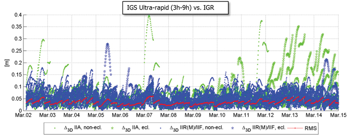
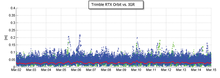
There are at least two strong reasons for justifying the need of implementing and running an RTX proprietary orbit processing server. The first one is simply the need of reliably meeting the above-mentioned requirements. The second one is that from an operational perspective, the RTX system is conceived in such a way that it does not rely on any external source of information to run at its full accuracy capability. Figure 4 shows the achieved orbit errors provided by IGS ultra-rapid products during two weeks of March 2011, where IGS rapid orbit products are used as truth. The ultra-rapid orbits are evaluated using the initial portion of the predicted arc, thus making use of the most reliable part of the predicted arcs as the products become available in real-time. In that case, neither accuracy nor continuity requirements for RTX processing are completely met.
FIGURE 4. IGS ultra-rapid orbit errors, as compared to IGS rapid orbit products.
Orbit Estimation. The orbit estimation in the CenterPoint RTX system is based on a combination of a UD-factorized Kalman filter estimating satellite position, satellite velocity, troposphere states, integer ambiguities, solar radiation pressure parameters, harmonic coefficients, and Earth-orientation parameters. The prediction step in the filter uses a numerical integration of the equations of motion in connection with a dynamic force modeling. Forces considered in the approach are: the Earth’s gravity field, lunar and solar direct tides, solar radiation pressure, solid earth tides, ocean tides, and general relativity.
In RTX orbit processing carrier phase integer ambiguities are resolved in real-time. Also, the satellite orbit states are truly estimated in real-time and continuously adapted over time to better represent the current reality. This means that the satellite positions that are evaluated by the user have prediction times of no more than a few minutes since the last orbit processing filtering update, providing negligible loss of accuracy. Figure 5 shows the orbit errors obtained from the RTX orbit processor. Similarly to the previous figure, IGS rapid orbit products are used as reference. The time span is also the same as in the previous figure. The RTX real-time orbit components have a typical overall accuracy of around 2.5 centimeters (cm), and a 3D error accuracy of around 4 cm, considering IGS rapid products as truth.
FIGURE 5. RTX real-time orbit errors, as compared to IGS rapid orbit products.
Clock Estimation. Satellite clock estimation forms an essential part of the RTX system. It plays a fundamental role on positioning performance due to a number of reasons. Satellite clocks map directly into line-of-sight observation modeling, yielding into a one-to-one error impact from clocks into GNSS observables modeling. Due to the same strong relationship, it is of fundamental importance that clocks are generated in a way to facilitate ambiguity resolution within the positioning engine. The processing speed of a clock processor is also of critical importance, due to the fact that any delay in computing satellite clocks is directly translated into correction latencies when computing real-time positions on the rover side. For that matter, one should keep in mind that regardless how late satellite corrections get to the GNSS receiver in the field, positions have to be provided to the user as soon as the rover GNSS measurements are available. Therefore latencies typically introduce errors into the final real-time position. In this article, we define real-time positioning as the computation of positions at the time when the rover observables are available, regardless of the latency of the correction stream. This is a necessary concept in order to support dynamic rover GNSS positioning.
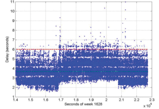
The RTX clock network processor was designed around the requirements discussed earlier. It computes clocks that are compatible with ambiguity resolution on the user receiver. As a matter of fact, the clock network processor itself employs ambiguity resolution for the generation of the RTX clocks. The processor architecture is based on an innovative design that allows processing data of several hundreds of reference stations, including all necessary steps such as data quality control, ambiguity resolution, and the final clock generation, within a fraction of second. The processing time of this kind of real-time network processor has to be minimized as much as possible in order to allow the processor to operate at 1 Hz, and to minimize the final correction latency at the rover end. Note that the final latency of the correction stream is a composition of three basic components: the time for the network data to arrive at the network processing server; the network processing time; and the correction transmission time to reach the final user. Figure 6 shows the typical total correction latency for the RTX system, when corrections are broadcast through a satellite link.
FIGURE 6. Typical RTX correction stream latency. The dashed green line represents the latency at 50 percent (3.7 s), and the dashed red line represents the latency at 99 percent (5.6 s).
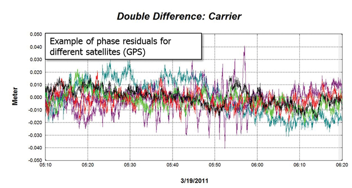
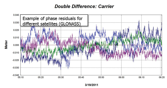
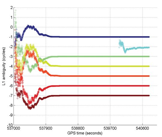
Unlike satellite orbits, satellite clock solutions are more difficult to compare directly. This is because different clock solutions might have offsets between each other, as well as behave differently due to differences in their GNSS reference time realization process as well as in their observation modeling approaches. That said, one way of verifying the quality of satellite clocks is to quantify how well it can be used to model actual receiver observation data. This can be in general achieved by applying satellite orbit and clock correction onto GNSS data and verifying the remaining residuals. Other quantities such as receiver coordinates have to hold their correct values for the residuals to be meaningful. In this case, the combined satellite orbit and clock error are assessed, and not just the satellite clock alone. For our purposes this is perfectly fine, since this is the way orbits and clocks are employed in rover positioning as well. Figures 7 and 8 show typical combined satellite orbit and clock errors at line-of-sight for different satellites. Figure 7 shows the ionospheric-free phase modeling error for GPS satellites, while Figure 8 is for GLONASS. Note that observations of a reference satellite (highest elevation at the time of observation) were reduced from the others. This was done in order to remove the receiver clock errors from the residuals. For both GPS and GLONASS cases, the observation modeling error after using RTX orbit and clock corrections is on average at the 1 cm level, with values typically less than 2 cm. The GPS satellite with outlying behavior in the plot below was setting at that time, and the increased amplitude of the residuals is mostly due to receiver observation errors such as multipath.
FIGURE 7. RTX clock quality (GPS) by means of corrected ionospheric-free phase measurements.
FIGURE 8. RTX clock quality (GLONASS) by means of corrected ionospheric-free phase measurements.
Communication and Positioning
Once all satellite information is available, it must be compressed in a message that can be broadcast to the user in the field. The transmission of global corrections can be done in different ways, such as via Internet, in case the user has access to it, or using a satellite link. In the latter it is customary that corrections sufficient to cover the transmission satellite footprint are broadcast, rather than corrections complete enough to cover the globe. Firstly, because it is expected that users operating inside the satellite footprint will use the corrections only for that region, and secondly because bandwidth restrictions usually play a role in message design for satellite-based communication. The bandwidth restrictions not only enforce maximum bandwidth utilization below a certain limit, but also require that the utilization over time is homogeneous to ensure optimal usage of the satellite channel.
Furthermore, satellite signals are typically susceptible to frequent message-packet losses depending on the user environment, such as when a receiver is running under canopy. To mitigate packet losses, the message must be built in such a way as to allow the rover to continue operations with minimum loss of availability. In that case not only the message design has to foresee this type of situation, but also the message decoding, usage, and positioning algorithms have to be optimized to most favorably couple with the received messages. All these factors have been taken into account in RTX system communication design. A new message format was created to carry information on satellite orbits, clocks, observation biases, and other auxiliary information. The new RTX CMRx satellite messages deliver 1-millimeter resolution for satellite orbits and clocks.
The RTX positioning engine inherits several technological aspects from Trimble’s pre-existing RTK engine. This aspect makes the RTX positioning mode, and traditional RTK positioning modes (for example, single base, virtual reference station) easy to co-exist. Among other things, the new engine has been thoroughly tested and optimized for challenging tracking environments. In these scenarios the engine is presented with observation data collected with a high level of multipath and low signal-to-noise ratio, often producing cycle slips and gaps in the data. As previously mentioned, at the same time the correction stream also suffers packet losses and the correction data might not be completely available during certain masking conditions.
Positioning Performance. The RTX engine delivers typical final accuracies at 1–2 cm level for horizontal positioning, and 2–4 cm for vertical, 1-sigma. The final convergence of the system is achieved in 10 to 45 minutes after receiver startup. The time to converge might depend on several aspects, including satellite geometry and multipath conditions.
To overcome the increased convergence time as compared to traditional RTK systems, a number of features have been implemented as part of the RTX positioning engine, two of which are worthy of mention here. The Fast Restart feature allows users to power up or place the receiver at a known location and immediately obtain a converged solution. This is also applicable when users have not moved their equipment since the last RTX solution. This feature is quite valuable in agriculture applications, where the user typically does not move the tractor between RTX-steered field work activities, thus avoiding in the majority of cases the need to wait through a new convergence period before starting work, one or more days after the last system usage.
The second feature is also related to avoiding system re-convergence. The Bridging feature, an outage recovery capability, enables the RTX positioning engine to immediately recover from a complete constellation outage with loss-of-lock during any dynamic activity. This prevents the system from entering a new convergence phase in case the receiver loses track of up to all satellites in view, coupled with outages of up to a couple of minutes, such as when running behind a tree line, or under a bridge.
Accuracy
Horizontal position error obtained in real time in a receiver acquiring the RTX correction data through the satellite link in North America is shown in Figure 9. The receiver was running continuously for several days, and was located in Ames, Iowa. As displayed, the horizontal RMS was 1.4 cm, with a 95 percent horizontal error of 2.4 cm. These are typical values for satellite-based RTX horizontal performance.
FIGURE 9. RTX real-time horizontal positioning performance. Results obtained from a receiver operating in Ames, Iowa.
Figure 10 shows the vertical performance for the same receiver and time period: the vertical RMS was 2.8 cm, with 95 percent vertical error of 4.4 cm.
Time to Achieve Convergence. Convergence is directly connected to the level of productivity that can be achieved for actual field applications. In the following example a continuously powered RTX receiver was used to show an assessment of the RTX (re-)convergence capability. The receiver’s tracking of all satellites was disabled every hour by an antenna switch. Each outage lasted three minutes, during which times no GNSS satellites were tracked.
FIGURE 10. RTX real-time vertical positioning performance.Results obtained from a receiver operating in AMES, Iowa, US.
This procedure was repeated hourly for several days in order to gather enough performance runs to derive meaningful statistics. Figure 11 shows the resulting performance of this assessment. The standard cold-start re-convergence performance is indicated with blue lines, where the solid lines represent 90-percent performance and the dashed line represents 68-percent performance.
As the figure shows, the RTX system converged to better than 5 cm horizontal error after 20 and 25 minutes for 68 percent and 90 percent of the runs, respectively. Convergence time is correlated with a number of aspects, including satellite geometry and multipath environment. Because of these variations, the claimed RTX convergence time is between 10 and 45 minutes for full accuracy achievement.
The red lines in Figure 11 indicate performance obtained with a second receiver, connected to the same antenna, and thus subject to the exactly same GNSS signal outages. This second receiver had the Bridging functionality enabled, and thus is expected to bridge the outages and phase cycle slips without resetting the positioning solution. The red lines confirm that the desired behavior is achieved. To better visualize what happens over time in this case, Figure 12 shows a few hours of the real-time results obtained with the receiver running with the Bridging functionality activated.
Figure 13 gives an example of Internet protocol (IP)-based RTX performance. This is a single run where the system converged to better than 5 cm (horizontal) in approximately 15 minutes. Figure 14 shows how the L1 ambiguities of individual satellites in view during that time converged.
FIGURE 13. RTX IP-based run example.
FIGURE 14. Example of ambiguities convergence during an RTX IP-based run.
In these two plots, positioning convergence is, as expected, highly correlated with the ambiguities convergence to their final integer values in cycles. Note that satellites that come in after the overall solution is converged (for example, in light blue) achieve their final ambiguity values much quicker than during the position convergence phase, also as expected. The proprietary algorithms used for ambiguity resolution and validation in RTX allow the ambiguities to reliably converge to their integer values. Arbitrary integer number of cycles have been removed from the original ambiguity values to allow better simultaneous visualization of the ambiguities for several satellites.
Optimizing the RTX system to work under different scenarios was necessary because the multipath and signal availability levels are reasonably different between running an antenna with a reference station setup and the actual user environment, where the data tracking conditions impose additional challenges on making high-accuracy positioning effective on a global basis, in a productive manner. Therefore, an extensive field test campaign was conducted during the pre-release phase of the RTX system. The next example shows RTX in-field performance for an precision agriculture application in Illinois. The setup is typical for agricultural use, with the antenna and receiver mounted on a tractor that ran for about 103 minutes. Figure 15 shows theactual track of the tractor; RTX corrections were received via satellite link.
FIGURE 15. RTX tractor field test track in Illinois.
The horizontal positioning performance for that field test can be seen Figure 16. The overall 2D RMS was 2.3 cm and the 95 percent horizontal error was 4.2 cm. Note that this position difference plot is between the RTX solution and a short-range single baseline (SBL) RTK solution providing truth. Therefore the numbers and plot actually show a combination of errors between the global RTX solution and the SBL solution to the local reference station.
FIGURE 16. Horizontal positioning results for a real-time RTX tractor field test in Illinois.
Nevertheless the error magnitudes achieved lie within the same range as in the previous assessments shown here.
Summary
RTX positioning brings together the advantages of positioning techniques that do not require local reference stations while providing the productivity of RTK positioning. Its deployment introduces innovations in GNSS network processing, as well as advancements in the rover global positioning algorithms.
RTX employs ambiguity resolution on a global scale for both network and rover processing, including GPS and GLONASS satellites in the solution. The delivery of this new technology is achieved through the CenterPoint RTX positioning service, capable of providing world-wide real-time centimeter-level accuracy without the direct use of a reference station infrastructure.
A longer version of this article was presented at the 2011 ION-GNSS conference in Portland, Oregon.
Rodrigo Leandro, Herbert Landau, Markus Nitschke, Markus Glocker, Stephan Seeger, Xiaoming Chen, Alois Deking, Mohamed Ben Tahar, Feipeng Zhang, Kendall Ferguson, Ralf Stolz, Nick Talbot, Gang Lu, Timo Allison, Markus Brandl, Victor Gomez, Wei Cao, and Adrian Kipka are members of the Trimble Engineering Team in Höhenkirchen, German