Thales Alenia Space is a joint company between Thales (67%) and Leonardo (33%).
EGNOS enhances the accuracy, reliability and integrity of positioning signals by improving the performance of GNSS. For instance, the EGNOS safety-of-life service is used in aviation for landings, enabling precision approaches at European airports without requiring ground guidance systems. The service has significantly improved operational safety and efficiency for European aviation.
Thales Alenia Space will build on its expertise in engineering, development, testing and maintenance of the existing EGNOS, along with its current development of EGNOS V2, to provide maintenance of the EGNOS V2 system for EUSPA and the European Union satellite navigation community from 2023 to 2026.
Thales Alenia Space will provide operational support and servicing in case of incidents — especially hardware and software troubleshooting and repairs — to deliver optimal 24/7 support for EGNOS. In addition, it will provide the upgraded or modified versions needed to ensure safety-of-life service.
The tests will assess whether UKSBAS can develop into a full operational capability to support safety-critical applications
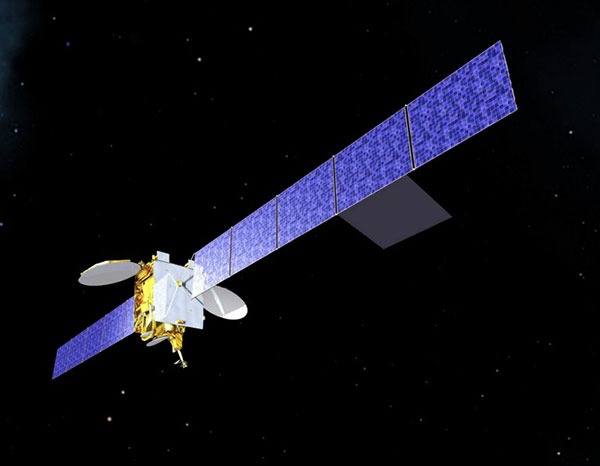
Artist’s impression of an Inmarsat-3 satellite. (Image: Inmarsat)
An Inmarsat-led team of companies in the United Kingdom has begun broadcasting a satellite navigation signal as part of a program to explore the creation of a sovereign national capability in resilient positioning, navigation and timing (PNT) for the aviation and maritime sectors.
The signal, being broadcast in coordination with the U.S. Federal Aviation Administration (FAA), the European Space Agency (ESA) and the European Union Space Programme Agency (EUSPA), is now stable and operational, enabling ongoing testing and validation by industry, regulators and users.
Inmarsat, a satellite communications company, alongside British partners Goonhilly Earth Station and GMV NSL, is delivering the UK Space Agency-funded tests with the European Space Agency via ESA’s Navigation Innovation and Support Program (NAVISP).
The UK Space-Based Augmentation System (UKSBAS) generates an overlay test signal to the U.S. GPS, compliant with International Civil Aviation Organization (ICAO) standards, to enable assessment of more precise, resilient and high-integrity navigation for maritime and aviation users in UK waters and airspace. It increases accuracy in positioning to a few centimeters of accuracy rather than the few meters provided by standard GPS.
This is a similar system to that already under evaluation in Australia and New Zealand, supported by Inmarsat.
Since leaving the European Union, the UK is not part of the Galileo satnav system and cannot use the European Geostationary Navigation Overlay Service (EGNOS) safety of life (SOL) services, which enable the use of GPS for airport approach and landing operations for aircraft. The UK ceased to have access to EGNOS on June 25, 2021.
By repurposing the SBAS transponder on Inmarsat’s I-3 F5 satellite in geostationary orbit at 54° west, the UKSBAS signal enables testing of this potential alternative system. Built by Inmarsat’s Athena partner Lockheed Martin and launched in 1998, I-3 F5 covers the UK as part of its Atlantic Ocean region service overlay. This makes it a suitable candidate to participate in this test and demonstrates the commitment to sustainability of Inmarsat with a satellite that has already served the equivalent of several low Earth orbit (LEO) satellite life cycles.
“The Inmarsat team is inspired by delivering solutions to new problems through technology and innovation,” said Todd McDonell, president, Global Government at Inmarsat. “Repurposing a transponder on a long-serving satellite to deliver a new capability to the UK, potentially a vital and enduring one, certainly lives up to that core Inmarsat ethos. Working with our fellow British companies at Goonhilly and GMVNSL to deliver such a capability for the country is very rewarding, and we look forward to reporting on the results.”
The tests will assess whether UKSBAS can develop into a full operational capability to support safety-critical applications such as airport approach and landing operations or navigating ships through narrow channels, especially at night and in poor weather conditions.
Goonhilly provides the signal uplink for the system from Cornwall; software from Nottingham-based GMVNSL generates the necessary navigational data.
“The UK’s thriving space sector is developing at pace, and British-led innovations like this have the potential to deliver crucial navigation services for our aviation and maritime sectors.” said Transport Minister Robert Courts. “That’s why this government is investing millions in new technologies to make our transport network even safer while boosting high-skilled job opportunities across the nation.”
UKSBAS is helping to regenerate UK strategic capabilities in this domain. The establishment of this new national platform creates the opportunity to evaluate high-integrity, resilient and precise navigation across the country, in its airspace and within surrounding waters. The project may be crucial for UK users who need accurate, high-integrity navigation capabilities to enable their operations, initially covering aviation and maritime operations but with potential extension into rail and road applications.
“Congratulations to Inmarsat, Goonhilly and GMVNSL on this impressive achievement,” said Paul Bate, CEO of the UK Space Agency. “In recent years, the UK Space Agency has invested in the development of UK expertise in positioning, navigation and timing (PNT), and the government’s commitment to strengthening PNT resilience is set out in both the National Space Strategy and Integrated Review, given its importance to our critical national infrastructure and economy. “This project is a great example of the innovation found throughout the UK space sector and demonstrates how we can work effectively with the European Space Agency to strengthen our national space capabilities.”
By Javier Benedicto
Head, Galileo Programme department,
European Space Agency
Javier Benedicto, left, accept the 2018 GPS World Satellites Leadership Award on behalf of Giuliano Gatti of the European Space Agency, from Phil Froom of Rockwell Collins. (Photo: Melanie Beus)
Since the Galileo initial services declaration in December 2016, the Galileo Program has been providing global PNT and search-and-rescue services for users worldwide. The European GNSS Agency (GSA) just issued its GNSS 2019 Market Report in October, providing a complete overview of the current status and trends of the GNSS worldwide market with focus on European GNSS (Galileo and EGNOS) applications and services.
In parallel with service provision, the Galileo Program is undertaking extensive infrastructure development and deployment activities to reach Full Operational Capability (FOC), incorporating new service capabilities, but above all aiming at increasing the robustness and resilience of the system infrastructure, operations and service provision.
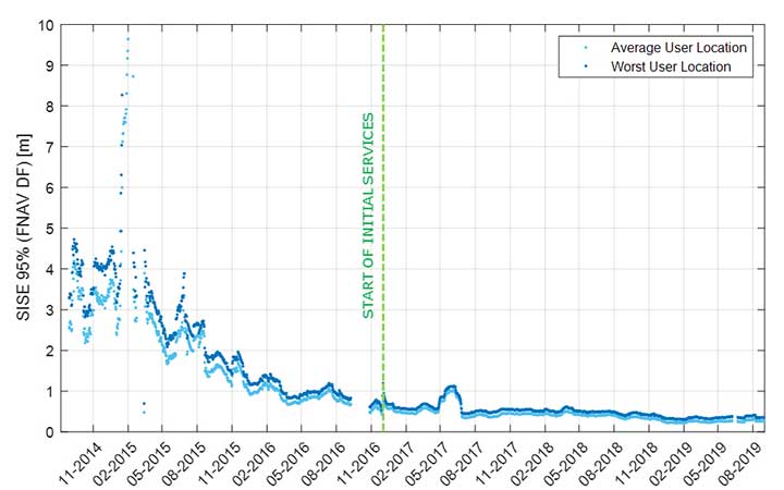
Galileo’s signal-in-space quality has steadily improved over the past few years, reaching in 2019 a best signal-in-space error (SISE) of about 0.25 meters (95%, global average; Figure 1). This has been achieved through a combination of several factors, including the increased number of operational satellites, enhanced versions of the Ground Mission Segment, and higher uplink rate of the navigation message (lower age of data). This performance is well within Galileo’s initial service accuracy commitments, as defined in the public Open Service – Service Definition Document (OS SDD).
Figure 1. Long-term historical SISE plot over a 30-day sliding window, constellation averaged. (Image: ESA)
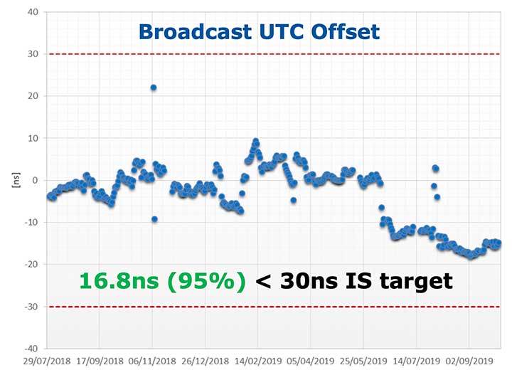
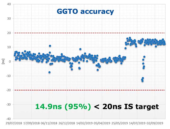
Figures 2 and 3 (see page 40) show Galileo’s timing performance as broadcast UTC offset and GGTO accuracy. The evaluation was performed with calibrated GPS/Galileo timing receivers operated in UTC(k) laboratory (PTB, INRIM). Again, the initial timing service commitments have been fully met.
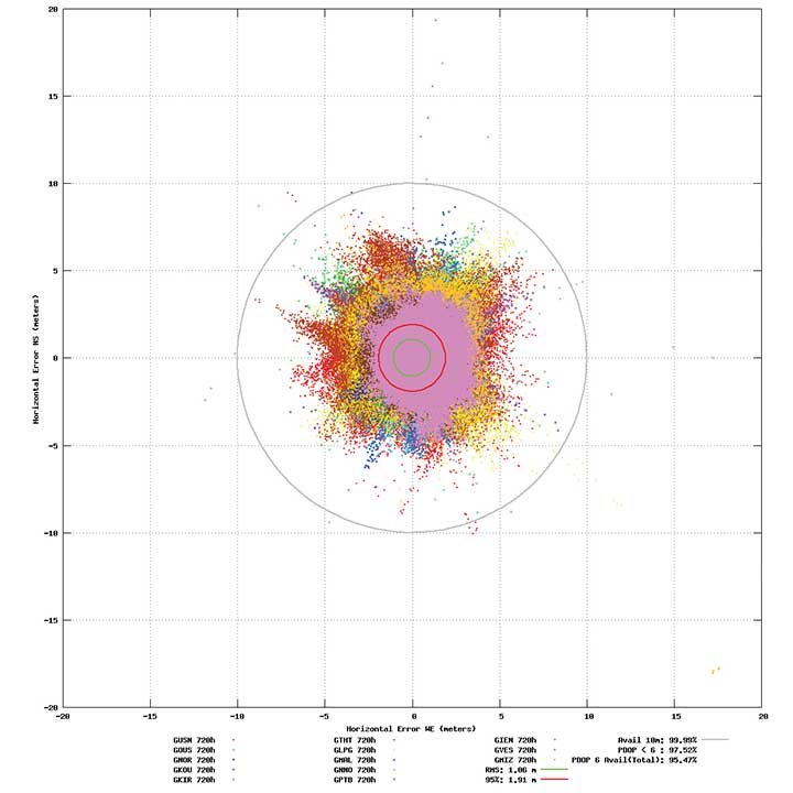
Probably the most significant discriminator of Galileo compared to other GNSS is its capability to broadcast multi-frequency (E1, E6, E5) signal components on all operational satellites. The position performance of a dual-frequency user receiver on-ground is shown in Figure 4. This measurement from June 2019 demonstrates a Galileo position accuracy well below 2 m (95%).
Figure 4. Galileo position accuracy performance, dual-frequency, June 2019. (Image: ESA)
With the aim of further improving the Open Service (OS) performance, three newly introduced I/NAV message improvements on Galileo E1-B are under implementation, namely FEC2 Reed-Solomon Clock and Ephemeris (CED), Reduced CED, and Secondary Synchronization Pattern (SSP). Galileo Open Service (OS) users will benefit from improved robustness in terms of navigation data retrieval in challenging environments, in addition to facilitating a reduced time to first fix. Those I/NAV improvements on Galileo E1-B are backwards compatible with previously released OS SIS ICDs.
In addition, Galileo infrastructure is currently being upgraded to provide means for OS authentication. The protocol proposed uses the E1B External Data Broadcast Service (EDBS) to provide authentication data to the user. The OS Navigation Message Authentication (NMA) is based on an adaptation of the Timed Efficient Stream Loss-tolerant Authentication (TESLA) protocol.
Beyond the OS, the Galileo system has been designed to allow for the dissemination of value-added data, such as high accuracy and authentication, in the E6B signal component. The component has been designed to broadcast the Galileo High Accuracy Service based on the provision of accurate satellite data (clocks, orbits and biases) and atmospheric data (mainly ionospheric corrections) to enable multi-frequency multi-constellation PPP with correction data transmitted through an open format in the Galileo E6B signal.
The introduction in early 2020 of the automatic acknowledgment of the SAR/Galileo Return Link Message (RLM) as part of the Cospas-Sarsat system will enable space assets to be used for search and rescue — persons in distress will get swift acknowledgement that their alert has been detected and located. The Return Link is the means to interact with a SAR beacon, improving the effectiveness of SAR operations. Extensive testing has demonstrated that the median latency for the reception of a return link message on the ground is 14.2 seconds, while 99% of messages are received within 57 seconds, after the request for the RLM transmission is delivered to Galileo (from Cospas-Sarsat to the RLSP). At the same time, the measured rate of reception was 100%, considering line-of-sight availability, thanks to the very robust Galileo navigation data link. This performance has been demonstrated to be uniform across the globe, as shown in Figure 5.
Figure 5. Beacon activation map and RLM delivery latency through the Galileo system. (Image: ESA)
Following the re-profiling of the Galileo Safety-of-Life (SoL) service, Galileo is meant to be exploited through dual-frequency multi-constellation (DFMC) SBAS and will support the provision of integrity through the concept of Horizontal Advanced Receiver Autonomous Integrity Monitoring (H-ARAIM). To allow the exploitation of Galileo for these SoL applications, a thorough analysis of the actual signal-in-space (SiS) performance and of potential feared events critical for SoL users is key. In this context, the Galileo Integrity Failure Mode and Effect Analysis (IFMEA) process is implemented through measurements and review of the system design, including feared-events characterization.
Ground Segment Brings Robustness
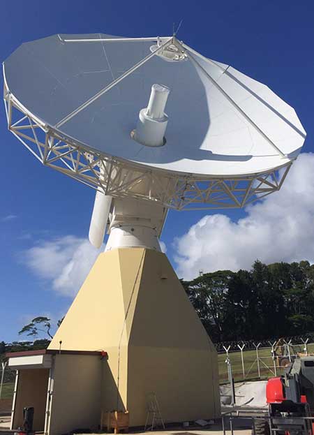
Galileo telemetry and telecommand ground station. (Photo: ESA)
Galileo’s Ground Segment is being upgraded to fully redundant control centers. These include processing and storage, monitoring and control facilities, and security monitoring centers. A worldwide network of Galileo Sensor Stations (GSS) allows monitoring and measuring of satellite signals; uplink stations allow dissemination of the navigation message to users through Galileo satellites; and telemetry, tracking and control (TTC) stations allow monitoring and control of the satellites.
Ground segment upgrades under production by Thales Alenia Space France (in charge of the ground mission segment and security monitoring) and GMV Spain (in charge of the ground control segment) are addressing increased service robustness, through the introduction of a more flexible infrastructure with a significant technology refresh, improved security, service continuity, enhanced service performances, and enhanced operability features.
One important objective of the ongoing upgrades is to implement a modern infrastructure, based on leading virtualization technologies. This modernized infrastructure will make it possible to easily accommodate hardware and software changes without requiring significant redesign or requalification, and will minimize the impact to Galileo service operations — under responsibility of Spaceopal GmbH — during future deployment activities.
Batch 3, Ariane 6 Under Production
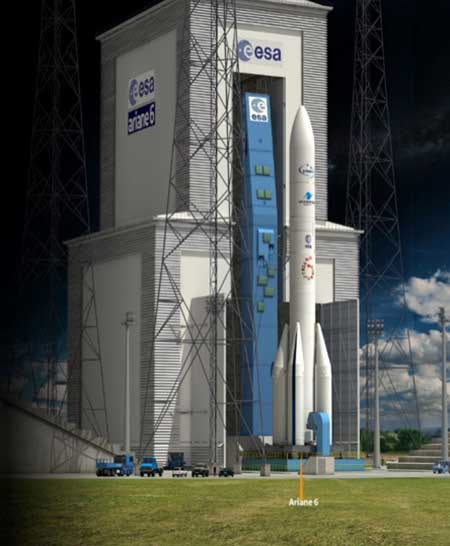
Ariane 6 on the launchpad. (Artist’s concept: ESA)
The production of Batch 3 of 12 additional Galileo FOC satellites is proceeding, aiming at readiness for launch by the end of 2020 onward. The satellite design includes a selected number of improvements compared to the 22 FOC satellites launched previously and built by the same satellite manufacturer OHB Systems.
The different stages of assembly, integration and initial test phase in the OHB production plant in Bremen have already started, before shipment to ESA-ESTEC in the Netherlands for the environmental test campaign consisting of thermal vacuum, mechanical tests, interface verification with the launcher and system end-to-end performance tests with the elements of the Galileo ground segment.
Following the phasing out of the Ariane 5 SE launcher, the third batch of Galileo satellites will be progressively launched with the new Ariane 62 launcher vehicle, the two solid-booster variant of Ariane 6 now in the final stages of development.
Evolution to Meet User Needs
The Galileo Second Generation roadmap has achieved maturity in 2019 and is now entering the preliminary design and implementation phase. Based on the EU’s H2020 Galileo Second Generation activities managed by ESA, and the GSA prospective market analysis, the European Commission, in close consultation with EU member states, has agreed on an ambitious set of long-term PNT goals for the future European GNSS infrastructures.
Technology pre-developments, critical engineering activities and synergic design activities between space and ground infrastructure are being conducted. This will translate into the progressive deployment of a complete set of space/ground infrastructure that is tailored to satisfy the diversified user needs in four main dimensions:
Satellite and ground segment infrastructure with capabilities that can dynamically adapt to current and future user needs. Key drivers are flexibility and robustness, ensuring fast time to market to meet user needs.
Full synergy between GNSS and SBAS systems infrastructure, to complement and enhance the service portfolio. This will allow segmentation and complementarity of safety-critical services and extension to all new PNT services available today, including high-accuracy positioning integrity.
Enhanced integration with terrestrial systems — 5G/6G, signals of opportunity (SOOP), terrestrial beacon systems (TBS). ESA and GSA have been actively leading the 5G positioning standardization worldwide in collaboration with public and private institutions inside 3GPP and will soon move toward the start of standardization of 6G terrestrial positioning and GNSS interconnection technologies.
Full complementarity with external sensors (such as INS, barometer and lidar) and application environments (low-power devices and internet of things) so that the Galileo Second Generation Infrastructure enhances and complements the capabilities provided by these external means.
A key pillar for this long-term strategy is the Galileo transition satellites. The competitive procurement procedure for the first batch of transition satellites is coming in 2020. The flexibility and robustness of these satellites will allow the European PNT infrastructure to satisfy all the different user needs in the next decade. This procurement — together with others at system, ground segment and technology level — will enable the start of the in-orbit validation of second-generation capabilities from 2025 onward.
Additional ground and test infrastructure are in early engineering analysis, design and technology development, in order to proceed with additional procurements for experimental and operational usage, starting early in the 2020s.
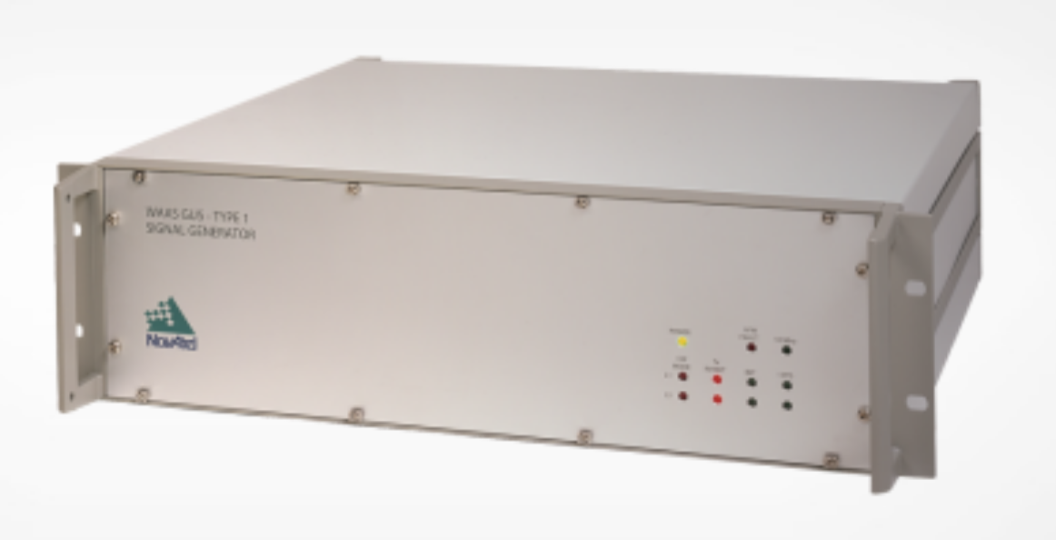
NovAtel has been awarded a contract from the United States Federal Aviation Administration (FAA) to design, produce and deliver 40 next-generation Ground Uplink Station (GUS) Signal Generators to support the FAA’s safety-of-life WAAS navigation service. The service provides safety-critical infrastructure for the North American aviation navigation network.
GUS signal generator. (Photo: NovAtel)
The contract also includes ongoing engineering support services for NovAtel’s complete portfolio of satellite-based augmentation system (SBAS) products deployed by the FAA, including the WAAS G-III reference receiver platform.
The FAA has relied on NovAtel’s safety-critical SBAS technology for more than 20 years, starting with NovAtel’s first-generation WAAS reference receiver that was created in the 1990s.
Developed by the FAA, the WAAS network is a safety-critical navigation aid that allows aircraft to use GPS for all phases of flight. Every time an aircraft takes off or lands within the WAAS coverage area, NovAtel technology is generating and processing data that allows aviators to make precision approaches to any airport.
Since the program’s inception, NovAtel has provided the FAA with technology that delivers high-precision GPS receiver measurements and navigation information from WAAS Reference Stations and the GUS infrastructure.
Under this new contract, NovAtel will help modernize the WAAS network by upgrading and extending support for the network’s GUS infrastructure. The next-generation of GUS signal generators, which are designed specifically for SBAS ground uplink systems, will include independent L1 and L5 signal paths to precisely control the frequency and phase of L1 and L5 code and carrier for dual-frequency SBAS.
A GUS receiver system based on the WAAS G-III receiver platform will also be released along with the signal generator to complete the modernized GUS control loop.
“We have a long history with the FAA and have worked very closely with the WAAS program team to develop multiple-generations of SBAS infrastructure,” said Jonathan Auld, vice president of engineering and safety critical systems at NovAtel. “NovAtel remains committed to supporting the FAA and their safety of life WAAS service and we are excited to deliver this critical next-generation technology for SBAS modernization.”
EGNOS V3 will offer improved and secure Civil Aviation Safety of Life services for the next decade over Europe. The program will ensure a full continuity of service and will be the first operational SBAS using both GPS and Galileo.
Airbus has been selected by the European Space Agency (ESA) as the prime contractor to develop EGNOS V3, the next generation of the European Satellite Based Augmentation System (SBAS) planned to provide the civil aviation community with advanced safety-of-life services and new services to maritime and land users.
Developed by ESA on behalf of the European Commission and the European GNSS Agency (GSA), EGNOS V3 (European Geostationary Navigation Overlay Service) will provide augmented operational safety-of-life services over Europe that improve the accuracy and availability of user positioning services from existing GNSS (Galileo and GPS).
EGNOS also provides crucial integrity messages to EGNOS users with alerts within a few seconds in case of system degradation, consolidating EGNOS’ position as one of the leading edge GNSS systems in the future.
Besides improved safety-of-life services, EGNOS V3 will improve robustness against increasing security risk, in particular cyber-security risks.
EGNOS V3 will ensure a full continuity of service for the next decade and will be the first operational SBAS implementing the dual-frequency and multi-constellation world standard, with both GPS and Galileo, replacing EGNOS V2 which has been in operation since 2011.
“This programme is strategic for Airbus to strengthen our position in the Navigation field. The signature of this contract is the result of more than 5 years of intense team work and investment,” said Nicolas Chamussy, head of Space Systems at Airbus. “With our consortium, we bring a large pool of resources and experience in Europe covering the successful development of critical and secure ground segment. I am confident that we will make EGNOS V3 a success story.”
As prime contractor, Airbus will be leading a consortium with partners from France, Germany, Spain and Switzerland. Airbus will be responsible for the development, integration, deployment and preparation of EGNOS V3 operations, the overall performance of the system and the Central Processing Facility, which is the heart of the real-time navigation algorithms.
During the 6.5-year contract, around 100 people and 20 subcontractors will work on delivering the EGNOS V3 system. In 2023, the single-frequency version will be available to replace the current operational version and, 18 months later, the final version in dual frequency will be delivered.
EGNOS is composed of a large network of about 50 ground stations deployed over Europe, Africa and North America, two master control centers near Rome and Madrid, and a System Operation Support Centre in Toulouse. EGNOS will also use geostationary satellite navigation payloads.
The European Space Agency (ESA) has signed a contract with Thales Alenia Space for an upgrade to Europe’s EGNOS satellite navigation augmentation system, which underpins the safety-critical use of satnav across Europe, according to ESA.
Designed by ESA and being exploited by Europe’s GNSS Agency (GSA), the European Geostationary Navigation Overlay Service (EGNOS) improves the precision of GPS signals over most European territory, while also providing continuous and reliable updates on the “integrity” of these GPS signals.
A network of ground monitoring stations throughout Europe performs an independent measurement of GPS signals, so that corrections can be calculated, and then passed to users immediately via a trio of geostationary satellites.
The result is that the EGNOS-augmented signals are guaranteed to meet the extremely high performance standards set out by the International Civil Aviation Organisation standard, adapted for Europe by Eurocontrol, the European Organisation for the Safety of Air Navigation.
Paul Verhoef, ESA director of the Galileo Program, and Philippe Blatt, VP Thales Alenia Space France, sign on June 6 a contract for an upgrade of EGNOS.
Paul Verhoef, ESA’s director of the Galileo programme and navigation-related activities, signed the contract at ESA Headquarters in Paris with Philippe Blatt, vice president of Thales Alenia Space France.
ESA is performing the procurement of EGNOS Version 2.4.2 under the overall program authority of the GSA, which oversees both EGNOS and Europe’s Galileo satellite navigation system.
Two upgraded EGNOS releases will be provided over the course of the development: EGNOS V2.4.2I and EGNOS V2.4.2A.
The releases will resolve various obsolescence issues related to EGNOS’s central processing facility, based in Toulouse, France — which generates the corrections and integrity information to be broadcast across the European continent — to ensure continuity of EGNOS services into the future, including safety-of-life services, to an ever-expanding community of users.
The new contract includes:
a refreshment and enhancement of the Central Processing Facility design without algorithm modification
an optimized qualification process
a guarantee of full compliance to safety-critical software development requirements
the performance of end-to-end verification activities extending to the three geostationary satellites used by the system
ensuring compliance to a new set of technical requirements and international standards.
By Ugo Celestino, European Commission, Antonella Di Fazio, Telespazio SpA, Vicente José Giner Herrera, Ineco, Patrizio Vanni, ENAV SpA, and Francisco Javier Deblas, ESSP.
This article describes a live demonstration of an aviation application in Tunisia, to help the local aviation community in validating the use of the European Geostationary Navigation Overlay Service (EGNOS) to guide airplanes during landing operations. This activity constitutes the first complete experience of EGNOS Safety of Life (SoL) service for aviation approaches outside Europe. We present here the obtained results that are useful not only for Tunisia, but as a valuable case study for other countries outside Europe interested in using EGNOS in aviation.
EGNOS, operational since 2009, has a European regional coverage that could be quite easily extended to areas adjacent to European Union through the deployment of limited additional ground infrastructure elements, but sharing the same existing space segment and leveraging the other core ground infrastructure.
The European Commission has put in place a series of actions since 2006 to support the EGNOS service extension in neighbouring areas. The MEDiterranean follow-Up for EGNOS Adoption (MEDUSA) is an on-going European initiative related to EGNOS extension in the Euromed region, including North African and Middle East countries around the Mediterranean basin: Algeria, Egypt, Israel, Jordan, Lebanon, Libya, Morocco, Palestine, Syria, and Tunisia. MEDUSA runs a program of technical assistance action in these Euromed countries, in order to prepare them for an optimal adoption and exploitation of European GNSS services in their priority market segments.
The Mediterranean Extension of EGNOS
EGNOS is Europe’s first venture into satellite navigation and paves the way for Galileo, Europe’s independent global satellite navigation system currently under deployment.
EGNOS is a satellite-based augmentation system (SBAS), whose signal is compliant to the international SBAS interoperability standards: standards – MOPS (Minimum Operational Performance Standards) and ICAO SARPs (International Civil Aviation Organization Standard and Recommended Practices). In its current version (V2) it augments the open public service offered by the American Global Positioning System (GPS), by providing correction data that enables to improve GPS position accuracy, and provides integrity information about the GPS system (integrity information is fundamental for aeronautical applications like approaches). EGNOS is interoperable with the other equivalent regional systems. Today other SBASs are the U.S Wide Area Augmentation System (WAAS), the Japanese Multi-functional Satellite Augmentation System (MSAS), the Indian GPS Aided Geo Augmented Navigation (GAGAN) and the Russian System for Differential Correction and Monitoring (SDCM). The future version (V3) of EGNOS will augment Galileo signal as well.
Today EGNOS is operational, and available for use in aviation since 2011, giving opportunities for users to have more accurate and reliable positioning for enhancing existing applications, developing new applications and particularly the safety critical ones. Already more than 150 landing procedures are operational across Europe (some of them also in countries out of the European Union, such as Switzerland, Norway, Guernsey), with many others under development to reach 100 percent Approaches with Vertical Guidance (APV) coverage in the European instrumental runways as per ICAO recommendation.
EGNOS provides three services:
EGNOS Open Service (OS), launched in 2009, is delivered free of charge. It is open for use to anyone with an EGNOS-enabled receiver. This can be any receiver compatible with satellite-based augmentation systems. Being based on GPS, the EGNOS signal does not require major changes for receivers. Today, many mass market receivers available on the market are also EGNOS enabled. EGNOS OS is particularly suitable for mass market and some applications like surveying.
EGNOS Safety-of-life Service (SoL) is authorized for European civil aviation and operational since March 2011. EGNOS SoL delivers the integrity message providing the verification of the GPS system and timely warnings (within six seconds), when the system or its data should not be used for navigation. Since integrity relates to the trust that can be placed in the correctness of the location information supplied by GPS, thanks to this feature EGNOS is able to meet the demands of safety-critical applications in sectors such as aviation.
EGNOS Data Access Service (EDAS) launched in 2012, delivers a terrestrial commercial data service. It consists of a server that gets the data directly from EGNOS system and disseminates it via terrestrial networks in real time, within guaranteed maximum delay, security and performance. EDAS is particularly suitable for professional applications. It provides EGNOS raw data and corrections enabling software solutions that implement products and value added services built on them.
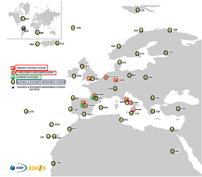
EGNOS infrastructure consists of three geostationary satellites over Europe and a network of ground stations (Ranging and Integrity Monitoring Station – RIMS) located to provide services whose coverage includes southern Europe, North Africa and some Middle East countries.
The EGNOS RIMS network supports a flexible network geometry that gradually adapts to service coverage requirements evolution. From the originally envisaged coverage over European Union’s countries, the EGNOS RIMS network is being expanded over Europe’s neighbouring areas, thus increasing the number of beneficiary countries. EGNOS SoL service is highly sought by several non-EU countries for the benefits it can bring to their civil aviation, in providing a solution to comply with ICAO requirements for Performance Based Navigation (PBN).
The present layout of the EGNOS RIMS network is presented in Figure 1.
Figure 1. EGNOS ground segment.
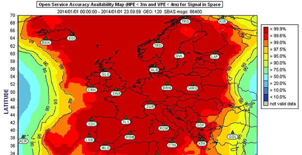
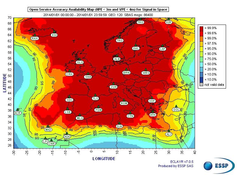
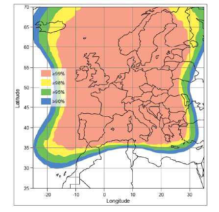
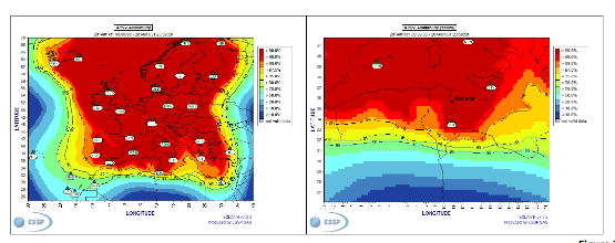
Figures 2 and 3 show respectively today’s coverage of EGNOS OS availability (source: European Satellite Services Provider, the service provider of EGNOS) and the APV-I availability performance commitment provided by EGNOS SoL (source: EGNOS Safety of Life Service Definition Document, EGN-SDD SoL, V2.0, European Commission, 2013), obtained relying on the above presented ground segment.
Figure 2. EGNOS OS Availability.
EGNOS OS Availability. The Figure 2 map is obtained by projecting the error at pseudorange level into the position domain. The computed error assumes that the GPS satellites used are those with an elevation angle above the local horizon (with a mask angle of 5º) and does not consider any possible factor depending on local characteristics that could produce different results (optimistic or pessimistic) with respect to the results computed using real receivers located in the considered areas. Moreover, it represents an estimation of EGNOS OS availability during a very limited period of time being an estimation, thus it does not imply any commitment or reference for the performances which can be obtained during different periods.
Figure 3. EGNOS APV-I Availability.
Other initiatives for a further extension in North Africa and Middle East are already being developed, under the umbrella of the Euromed GNSS programme. In parallel with the infrastructure deployment, the Euromed GNSS programme also includes actions to support the introduction and exploitation of EGNOS services. The first stage was completed in the frame of the Euromed GNSS I/MEdiTerranean Introduction of GNSS Services (METIS) project in the period 2006-2009, the second stage is presently running in the frame of the Euromed GNSS II/MEDUSA project. Further initiatives are being planned for 2015 and beyond.
EGNOS Use in Aviation
EGNOS was initially designed and developed to be used in aviation, similarly to the U.S. Federal Aviation Administration WAAS, to support different types of aviation applications and, in particular, to meet the performance requirements set by the International Civil Aviation Organization (Annex 10) for the implementation of APV-I, which enable the implementation of LPV final approaches, as reported in Table 1.
Table 1. ICAO Operational Requirements.
EGNOS is one of the GNSS elements recognised by ICAO (Annex 10) as a radionavigation aid. It is an important element of a global SBAS systems mosaic, that started with the American system WAAS in 2003, and that is gradually completed by other more recent SBAS: EGNOS itself, MSAS (Japan), GAGAN (India), SDCM (Russia), and some countries like Australia and South Korea that have launched feasibility studies to develop their own SBAS.
It is expected that, in a not too far future, most parts of the world will profit from SBAS services, following the current coverage extension plans and SBAS system evolutions. The final objective, as also shared at ICAO level, is that as many airdromes worldwide, as possible, can offer instrument approaches with vertical guidance, with an outstanding increase in global safety rates.
Additionally, the use of EGNOS allows taking full advantage of GNSS for all phases of flight, including final approach. Therefore, EGNOS means for aviation a fundamental and strategic tool to help meet ICAO’s recommendations, aimed at the adoption of a PBN oriented airspace use policy, for all countries. The 37th Assembly of ICAO (28 September – 8 October 2010) resolved that APV procedures should be implemented as either a primary or backup strategy for precision approaches at all instrument runway ends by 2016.
APV is a major safety initiative. ICAO recognises SBAS and Barometric Vertical Navigation (Baro-VNAV) as the two acceptable (and often complementary) means of implementing APV procedures, which are safer than NPA (Non Precision Approach).
GNSS based navigation enables RNAV (aRea NAVigation) with a higher cost effectiveness in comparison with the old conventional, sensor ground-based, navigation procedures. This is especially true for wide, even desert unequipped areas (or difficult to maintain) like those in North Africa and Middle East.
EGNOS benefits are maximized in final approach manoeuvres, providing GNSS lateral and vertical guidance, and enabling APV-I approaches.
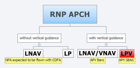
Final approach procedures based on GNSS are classified as RNP approaches (RNP APCH, as shown in the next figure), namely: Lateral Navigation (LNAV) with GPS lateral guidance and no vertical guidance; LP with GPS + SBAS (EGNOS) for lateral guidance (CAT-I localizer performance) and no vertical guidance; Lateral Navigation/Vertical Navigation (LNAV/VNAV) with GPS lateral guidance and Baro-Vertical Navigation (VNAV) vertical guidance (Baro-VNAV approach procedures can be flown with SBAS vertical guidance upon the approval of the Air Navigation Service Provider (ANSP)) and the LPV (Localizer Performance with Vertical Guidance) with GPS + EGNOS for both lateral and vertical guidance.
Figure 4. RNP approaches.
Those procedures not including vertical guidance are intended to be flown with the Constant Descent Final Approach (CDFA) technique (to avoid dangerous dive and drive practices), supported by most Flight Management Systems (FMS).
Regarding the operational LPV main figures, the European regulation (EU OPS -REGULATION (EC) No 859/2008 usually known as EU OPS) allows LPV operational minima (Decision Height – DH) down to 250 ft, expected to be possibly lowered down to 200 ft by 2015 (LPV-200), similarly to what is already permitted by the FAA, in the United Sates for WAAS based LPV approaches (a DH of 200 ft would make LPV approaches very competitive, when benchmarked against ILS CAT-I, precision approach, or even Ground Based Augmentation System (GBAS) CAT-I precision approach).
In the last few years, about 150 LPV procedures (status as of July 2014) have been published in European airports, and the number of procedures and countries introducing EGNOS is continuously increasing.
Euromed GNSS I/METIS and Euromed GNSS II/MEDUSA
In parallel with the development of the infrastructures necessary for extending EGNOS availability across the Euromed region, the European Commission has put in place initiatives to prepare and assist the Euromed countries for the optimal use and adoption of the relevant services.
These consist in two sequential projects, the first being Euromed GNSS I/METIS project and the second being Euromed GNSS II /MEDUSA.
Running from mid 2006 up to the end of 2009, METIS acted as a pioneer in the Euromed countries and built national/regional liaisons with decision-makers and key stakeholders, interested in sharing experience and absorbing know-how. The project assisted the 10 Euromed countries to identify their priorities in relation to the use of EGNOS services, to validate the relevant opportunities from the strategic/social and economic perspectives, and to elaborate a suitable strategy and a plan of actions for facilitating EGNOS adoption and exploitation.
MEDUSA Case Study in Tunisia: LPV Approaches in the Airport of Monastir Using EGNOS
As part of the technical assistance actions programme in the priority domains, MEDUSA implements demonstrations and validations of EGNOS services in concrete applications.
For EGNOS SoL, the technical assistance action consisted in the validation of GNSS approaches, including LPV approaches, designed and constructed in MEDUSA along with the relevant safety assessment and business case for the airport of Monastir in Tunisia (35°45’29’’ N 10°45’17’’ E). The selection of the airport was driven by a trade off between the EGNOS service availability with required APV-I performances and the specific needs of the Tunisian Air Navigation Service Provider – ANSP (OACA, Office de l’Aviation Civile et des Aéroports). According to OACA, Monastir is among the airports in Tunisia presenting favourable conditions, in terms of operational constraints and traffic, for concretely proving the added value of EGNOS for final approaches.
The airport has two runways, RWY 07 and RWY 25, the former is equipped with an ILS CAT-I, the latter only supports NPA approaches. The installation of an ILS in RWY 25 was discarded due to technical constraints. This infrastructure has proven to be insufficient to fully cover the airport needs, that suffers some Delays-Diversions-Cancellations (DDCs) as a result of local specific meteorological conditions, frequent fog banks entering from the sea in the early morning, combined with desert haze. These conditions make LPV ideal procedures, as backups to RWY 07, and enabling APV approaches to RWY 25. Finally, Monastir’s TWR ATC (Tower Air Traffic Control ) staff has been involved in OACA’s PBN development, for which they were ideal candidates to evaluate the benefits possibly achievable from the use of EGNOS.
This MEDUSA’s technical assistance action is the first complete experience for the use of EGNOS SoL service outside Europe. It was conceived as a realistic exercise of RNP APCH procedures implementation, following the guidelines provided by ICAO in the “EUR RNP APCH Guidance Material (EUR Doc 025)” and including all the activities required, from the scenario adequacy study to flight validation and the requirements analysis for the final publication in the AIP (Aeronautical Information Publication). OACA was directly involved in all activities, providing inputs/feedbacks and for training purposes.
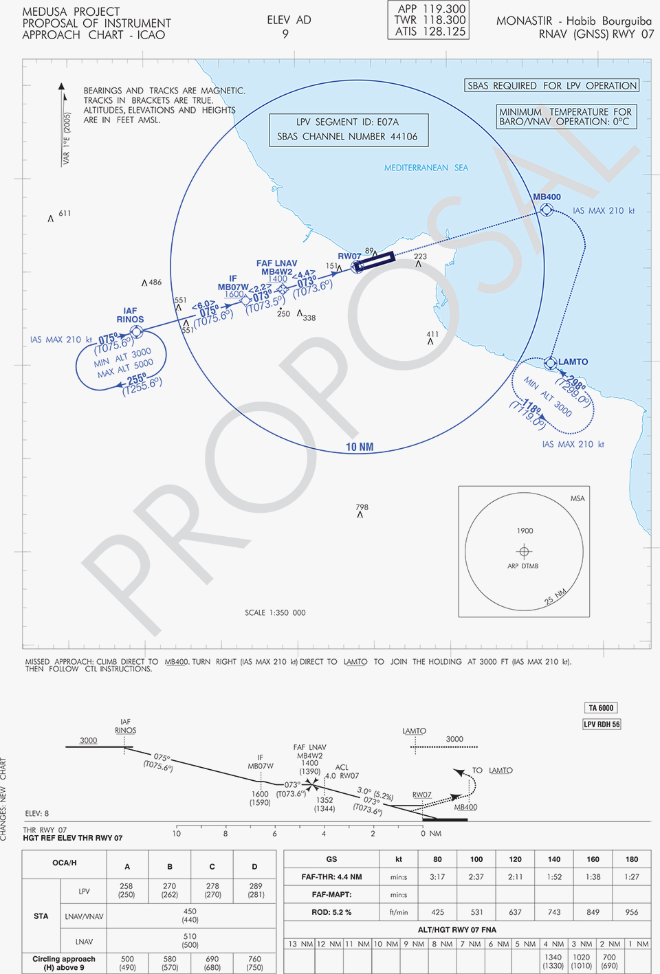
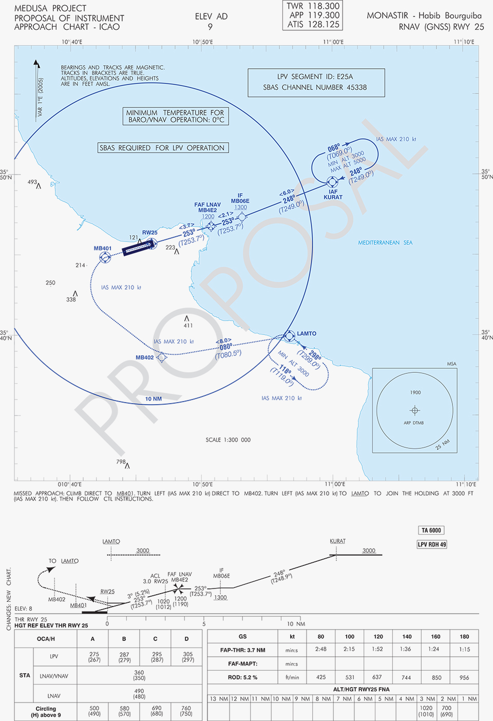
A set of three GNSS based approach procedures was produced for each RWY, following ICAO 8168 PANS OPS design principles. The next figures show the combined charts type elaborated, that include minima boxes for three RNP approaches (LNAV, LNAV/VNAV and LPV). The procedures construction preserves the current Monastir arrivals structure, following airspace management principles and facilitating the operational approval. As illustrated in the charts, in both cases for the three minima the calculated OCH (Obstacle Clearance Height) values improve with respect to the already existing conventional approaches, providing significant operational and safety benefits.
Figure 5. GNSS approaches for RWY 07.Figure 6. GNSS approaches for RWY 25.
An on-site GNSS performance monitoring campaign was performed by OACA, with the support of GEMCO’s staff, 3 months before the flight trials schedule, covering both EGNOS and GPS signal performances. Besides, an APV-I availability study for the area and specifically for Monastir airport during 1 month before the flight validation was purposely elaborated by the European EGNOS service provider (ESSP). Both analyses, confirmed suitable APV-I performance in terms of availability and continuity, making feasible the implementation of LPV approach procedures in line with ICAO prescriptions.
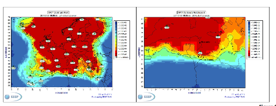
The next figures show the EGNOS APV-I availability and continuitymeasured on one day during the period of the flight validation (conducted from 30 January to 1 February 2014), in particular at Monastir airport for the considered time-lag:
APV-I availability was over 99%;
APV-I continuity presented a total value lower than 5×10⁻⁴/15s;
95th percentile of Horizontal APV-I accuracy was between 1.1 and 1.2 meters and the 95th percentile of Vertical APV-I Accuracy is around 1.4 meters, thus showing a very good accuracy level;
Horizontal and Vertical safety indexes were lower than 0.25, representing a very good integrity margin.
Additionally, the results of the on-site GNSS performance monitoring campaign showed quite stable performances with small fluctuations during the whole period of observation, and no problems or outages were observed.
(EGNOS APV-I Availability is defined as the percentage of epochs in a month in which the Protection Level are below Alert Limits for this APV-I service (HPL<40m and VPL<50m) over the total period (source: ESSP).
EGNOS APV-I Continuity Risk is defined as the result of dividing the total number of single continuity breaks using a time-sliding window of 15 seconds by the number of samples with valid and available PA navigation solution. A single continuity break occurs if the system is available at one epoch and becomes not available for the following 15 seconds (source: ESSP).)
Figure 7. APV-I availability on 31.01.2014.Figure 8. APV-I continuity on 31.01.2014.
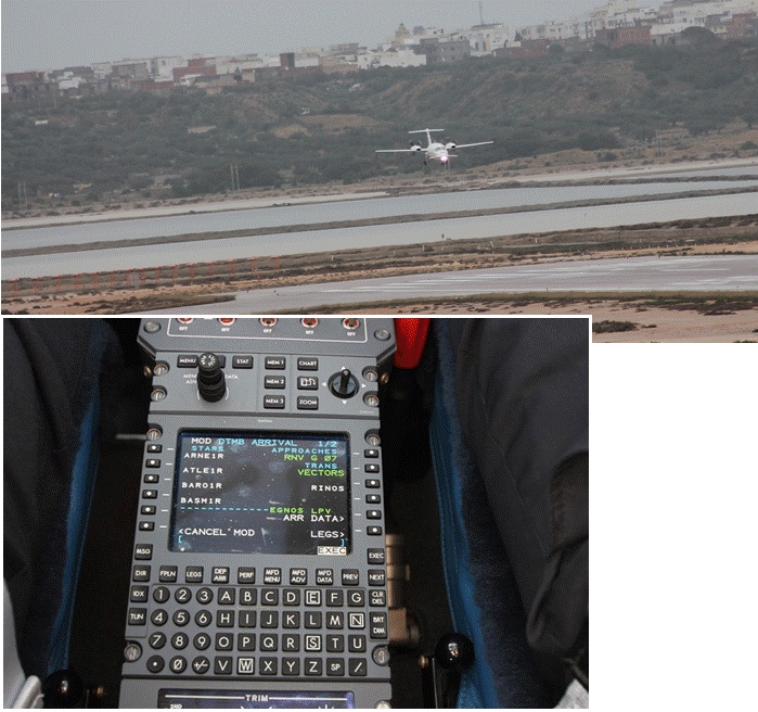
The flight validation campaign was carried out according to ICAO doc 9906 with a Piaggio P180 Avanti II (from ENAV flight inspection department) suitably equipped with UNIFIS 3000 system and a Rockwell Collins FMS 3000 with SBAS LPV approach capabilities.
Figure 9. Piaggio P180 Avanti II aircraft and the FMS messages during the flight validation.
The outcomes of this concrete experience have allowed the Tunisian authorities to identify the main elements for the publication of the validated procedures in their national AIP. They have also contributed to the analysis of the necessary process for the operational adoption of GNSS, including EGNOS, in aviation in countries beyond the EU boundaries.
The activities performed on performance assessment have been preparatory for discussions on GNSS monitoring and data recording on going at ICAO Navigation System Panel level, that would produce ICAO guidelines for States.
Therefore, this Tunisia’s “case study” represents a practical and realistic example that could be beneficial for the other non-EU countries in terms of best practice and lesson learnt. Moreover, methodology and guidelines have been derived to be possibly injected to other non-European countries interested to introduce EGNOS operations in aviation.
Lessons Learned and Outlook
Through its achievements, MEDUSA is opening the way for the introduction of EGNOS SoL service in North Africa and Middle-East region, and it is also defining a suitable path to be followed by other interested non-European countries. Overall, MEDUSA is continuing to confirm the ability to foster cooperation and involvement in EGNOS programme of the great majority of the Euromed countries. Further to Tunisia, other Euromed countries have already expressed their interest in relation to the EGNOS use in aviation, considering each country’s strategy and also in the light of a common shared regional perspective. Besides, the results obtained by MEDUSA are useful also for other regions interested to use EGNOS in aviation.
Additionally, MEDUSA is clearly showing that Euromed region, presently lacking the full support of SBAS technologies, represents an opportunity for EGNOS service extension, with many benefits for the countries of the region and for Europe.
On one hand, being SBAS an effective and efficient technology to enable the aviation community of the Euromed countries to comply with ICAO recommendations on PBN implementation by year 2016 across the region, the services coverage extension of existing SBAS systems (EGNOS in the case of the Euromed countries) can be one of the most efficient ways to move forward. In fact, the Euromed national ANSPs consider the readiness of EGNOS SoL service as one of the main drivers and factors when designing their PBN strategy. EGNOS, which is already operational since 2009 and available for use in aviation since 2011, can deliver added-value services to the Euromed region, just by leveraging the existing European infrastructure with only incremental, marginal and natural extension. The EGNOS coverage extension across the Euromed region can provide significant benefits and particularly to those Euromed countries with few ILS or reduced navaids coverage, and enhance safety and efficiency to the whole aviation community.
On the other hand, the European Union has to gain from an EGNOS-based long term links with its neighbouring regions, by increasing bilateral/multilateral cooperation and interaction (e.g. assistance, mutual cooperation) among public and semi-public bodies (e.g. ANSPs, Civil Aviation Authorities), by strengthening EGNOS SoL coverage in the southern/peripheries of EU (e.g. Malta, Cyprus, Greece, Southernest Italian islands, Canary islands), by pursuing and supporting other EU policies in several sectors (like transports, e.g. harmonizing aviation safety standards across the Mediterranean, Transport Policy of the Mediterranean Partners), and last but not least by achieving a first step towards EGNOS extension to the whole African continent which will bring in similar, additional benefits just described above.
By Axel van den Berg, Tom Willems, Graham Pye, and Wim de Wilde, Septentrio Satellite Navigation, Richard Morgan-Owen, Juan de Mateo, Simone Scarafia, and Martin Hollreiser, European Space Agency
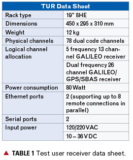
A fully stand-alone, multi-frequency, multi-constellation receiver unit, the TUR-N can autonomously generate measurements, determine its position, and compute the Galileo safety-of-life integrity.
Development of a reference Galileo Test User Receiver (TUR) for the verification of the Galileo in-orbit validation (IOV) constellation, and as a demonstrator for multi-constellation applications, has culminated in the availability of the first units for experimentation and testing. The TUR-N covers a wide range of receiver configurations to demonstrate the future Galileo-only and GPS/Galileo combined services:
Galileo single- and dual-frequency Open Services (OS)
Galileo single- and dual-frequency safety-of-life services (SoL), including the full Galileo navigation warning algorithms
Galileo Commercial Service (CS), including tracking and decoding of the encrypted E6BC signal
GPS/SBAS/Galileo single- and dual- frequency multi-constellation positioning
Galileo single- and dual-frequency differential positioning.
Galileo triple-frequency RTK.
In parallel, a similar test user receiver is specifically developed to cover the Public Regulated service (TUR-P). Without the PRS components and firmware installed, the TUR-N is completely unclassified.
Main Receiver Unit
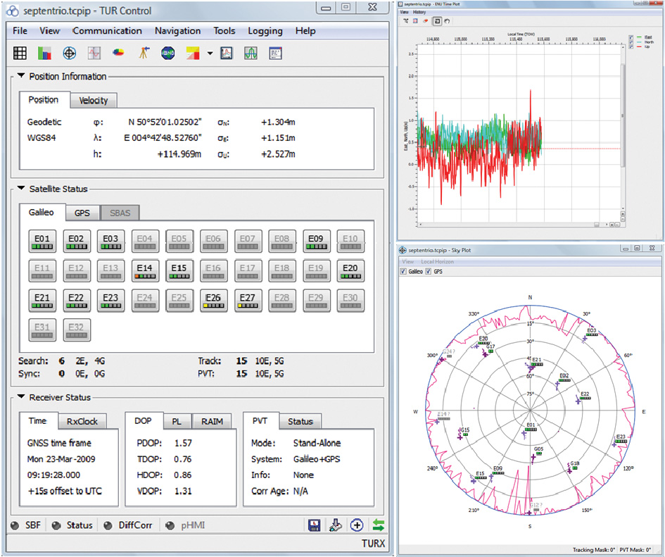
The TUR-N receiver is a fully stand-alone, multi-frequency, multi-constellation receiver unit. It can autonomously generate measurements, determine its position, and compute Galileo safety-of-life integrity, which is output in real time and/or stored internally in a compact proprietary binary data format.
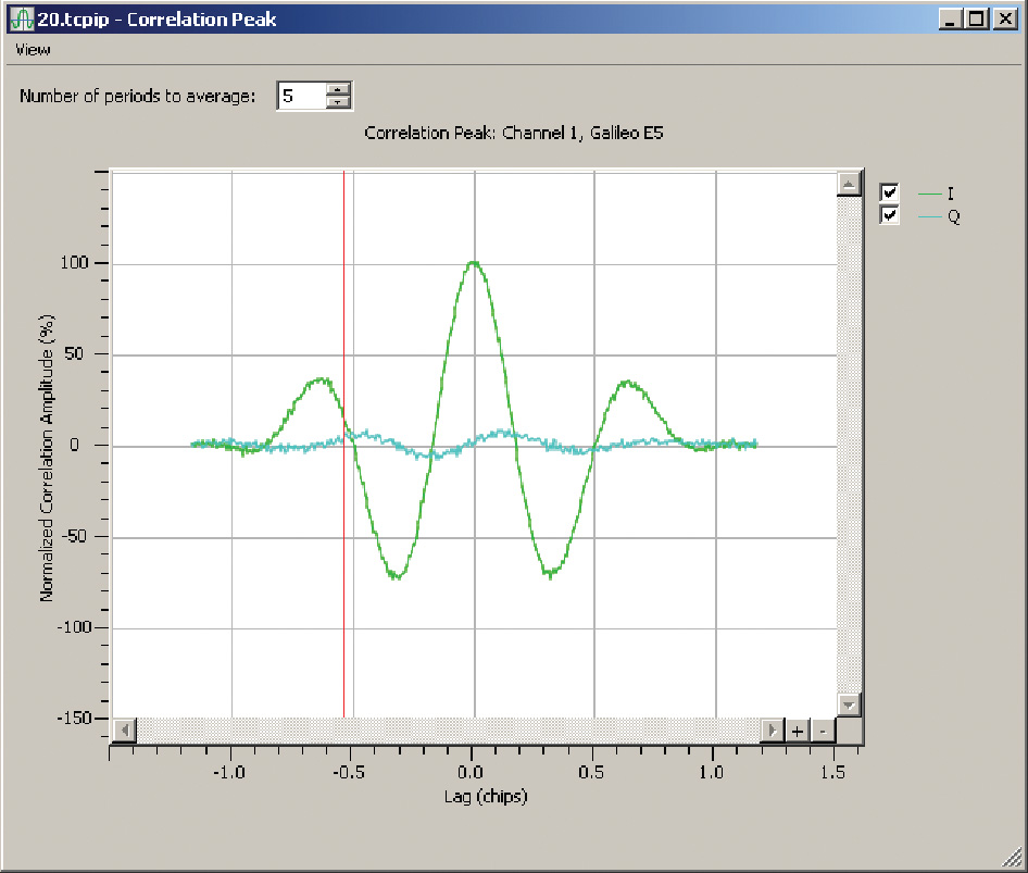
The receiver configuration is fully flexible via a command line interface or using the dedicated graphical user interface (GUI) for monitoring and control. With the MCA GUI it is also possible to monitor the receiver operation (see Figure 1), to present various real-time visualizations of tracking, PVT and integrity performances, and off-line analysis and reprocessing functionalities. Figure 2 gives an example of the correlation peak plot for an E5 AltBOC signal.
FIGURE 1. TUR-N control screen.FIGURE 2. E5 AltBOC correlation peak.
A predefined set of configurations that map onto the different configurations as prescribed by the Test User Segment Requirements (TUSREQ) document is provided by the receiver.
The unit can be included within a local network to provide remote access for control, monitoring, and/or logging, and supports up to eight parallel TCP/IP connections; or, a direct connection can be made via one of the serial ports.
Receiver Architecture
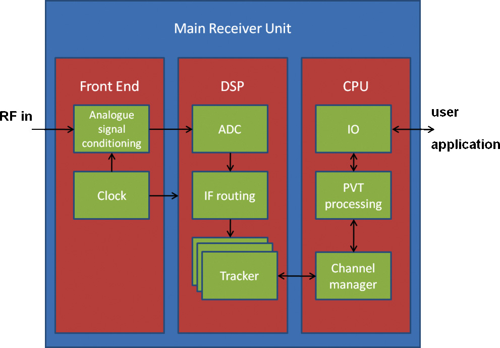
The main receiver unit consists of three separate boards housed in a standard compact PCI 19-inch rack. See Figure 3 for a high-level architectural overview.
FIGURE 3. Receiver architecture.
A dedicated analog front-end board has been developed to meet the stringent interference requirements. This board contains five RF chains for the L1, E6, E5a/L5, E5b, and E5 signals. Via a switch the E5 signal is either passed through separate filter paths for E5a and E5b or via one wide-band filter for the full E5 signal. The front-end board supports two internal frequency references (OCXO or TCXO) for digital signal processing (DSP).
The DSP board hosts three tracker boards derived from a commercial dual-frequency product family. These boards contain two tracking cores, each with a dedicated fast-acquisition unit (FAU), 13 generic dual-code channels, and a 13-channel hardware Viterbi decoder. One tracking core interacts with an AES unit to decrypt the E6 Commercial Service carrier; it has a throughput of 149 Mbps.
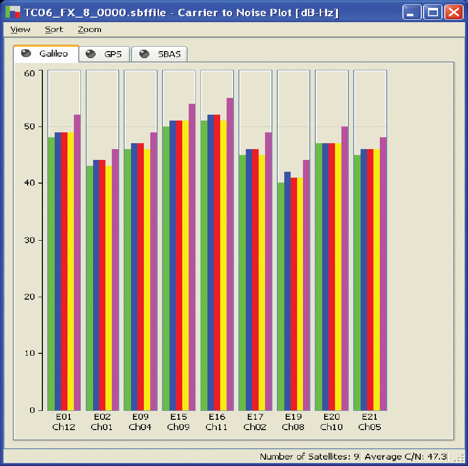
Each FAU combines a matched filter with a fast Fourier transform (FFT) and can verify up to 8 million code-frequency hypotheses per second. Each of the six tracker cores can be connected with one of the three or four incoming IF streams. To simplify operational use of the receiver, two channel-mapping files have been defined to configure the receiver either for a 5-frequency 13-channel Galileo receiver, or for a dual-frequency 26-channel Galileo/GPS/SBAS receiver. Figure 4 shows all five Galileo signal types being tracked for nine visible satellites at the same time.
FIGURE 4. C/N0 plot with nine satellites and all five Galileo signal types: L1BC (green), E6BC (blue), E5a (red), E5b (yellow), and E5 Altboc (purple).
The receiver is controlled using a COTS CPU board that also hosts the main positioning and integrity algorithms. The processing power and available memory of this CPU board is significantly higher than what is normally available in commercial receivers. Consequently there is no problem in supporting the large Nequick model used for single-frequency ionosphere correction, and achieving the 10-Hz update rate and low latency requirements when running the computationally intensive Galileo integrity algorithms. For commercial receivers that are normally optimized for size and power consumption, these might prove more challenging.
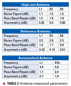
The TUR project included development of three types of Galileo antennas:
a triple-band (L1, E6, E5) high-end antenna for fixed base station applications including a choke ring;
a triple-band (L1, E6, E5) reference antenna for rover applications;
a dual-band (L1, E5b) aeronautic antenna for SOL applications
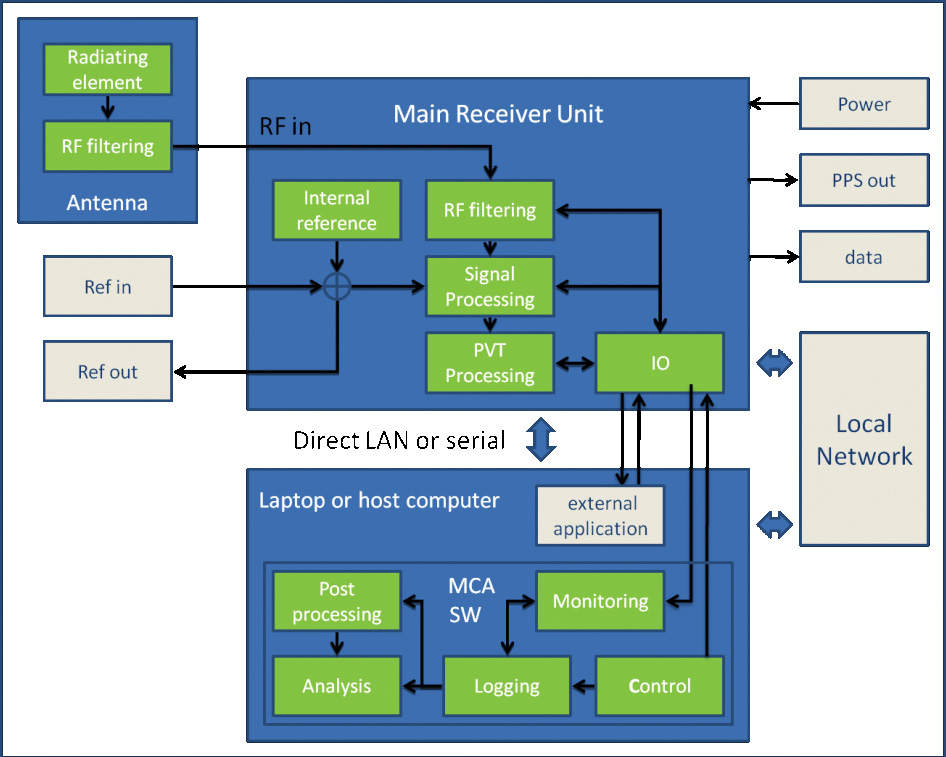
Figure 5 shows an overview of the main interfaces and functional blocks of the receiver, together with its antenna and a host computer to run the MCA software either remotely or locally connected.
FIGURE 5. TUR-N with antenna and host computer.
Receiver Verification
Currently, the TUR-N is undergoing an extensive testing program. In order to fully qualify the receiver to act as a reference for the validation of the Galileo system, some challenges have to be overcome. The first challenge that is encountered is that the performance verification baseline is mainly defined in terms of global system performance. The translation of these global requirements derived from the Galileo system requirements (such as global availability, accuracy, integrity and continuity, time-to-first/precise-fix) into testable parameters for a receiver (for example, signal acquisition time, C/N0 versus elevation, and so on) is not trivial. System performances must be fulfilled in the worst user location (WUL), defined in terms of dynamics, interference, and multipath environment geometry, and SV-user geometry over the Galileo global service area.
A second challenge is the fact that in the absence of an operational Galileo constellation, all validation tests need to be done in a completely simulated environment. First, it is difficult to assess exactly the level of reality that is necessary for the various models of the navigation data quality, the satellite behaviour, the atmospheric propagation effects, and the local environmental effects. But the main challenge is that not only the receiver that is being verified, also the simulator and its configuration are an integral part of the verification. It is thus an early experience of two independent implementations of the Galileo signal-in-space ICD being tested together. At the beginning of the campaign, there was no previously demonstrated or accepted test reference.
Only the combined efforts of the various receiver developments benchmarked against the same simulators together with pre-launch compatibility tests with the actual satellite payload and finally IOV and FOC field test campaigns will ultimately validate the complete system, including the Galileo ground and space segments together with a limited set of predefined user segment configurations. (Previously some confidence was gained with GIOVE-A/B experimental satellites and a breadboard adapted version of TUR-N). The TUR-N was the first IOV-compatible receiver to be tested successfully for RF compatibility with the Galileo engineering model satellite payload.
Key Performances
Receiver requirements, including performance, are defined in the TUSREQ document.
Antenna and Interference. A key TUSREQ requirement focuses on receiver robustness against interference. It has proven quite a challenge to meet the prescribed interference mask for all user configurations and antenna types while keeping many other design parameters such as gain, noise figure, and physical size in balance. For properly testing against the out-of-band interference requirements, it also proved necessary to carefully filter out increased noise levels created by the interference signal generator.
Table 2 gives an overview of the measured values for the most relevant Antenna Front End (AFE) parameters for the three antenna types. Note: Asymmetry in the AFE is defined as the variation of the gain around the centre frequency in the passband. This specification is necessary to preserve the correlation peak shape, mainly of the PRS signals.
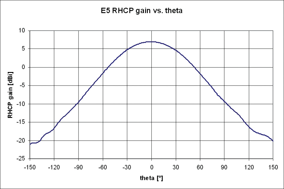
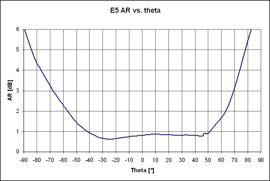
The gain for all antenna front ends and frequencies is around 32 dB. Figures 6 and 7 give an example of the measured E5 RHCP radiating element gain and axial ratio against theta (the angle of incidence with respect to zenith) for the high-end antenna-radiating element. Thus, elevation from horizontal is 90-theta.
UERE Performance. As part of the test campaign, TUR performance has been measured for user equivalent range error (UERE) components due to thermal noise and multipath.
TUSREQ specifies the error budget as a function of elevation, defined in tables at the following elevations: 5, 10, 15, 20, 30, 40, 50, 60, 90 degrees. The elevation dependence of tracking noise is immediately linked to the antenna gain pattern; the antenna-radiating element gain profiles were measured on the actual hardware and loaded to the Radio Frequency Constellation Simulator (RFCS), one file per frequency and per antenna scenario. The RFCS signal was passed through the real antenna RF front end to the TUR. As a result, through the configuration of RFCS, real environmental conditions (in terms of C/N0) were emulated in factory.
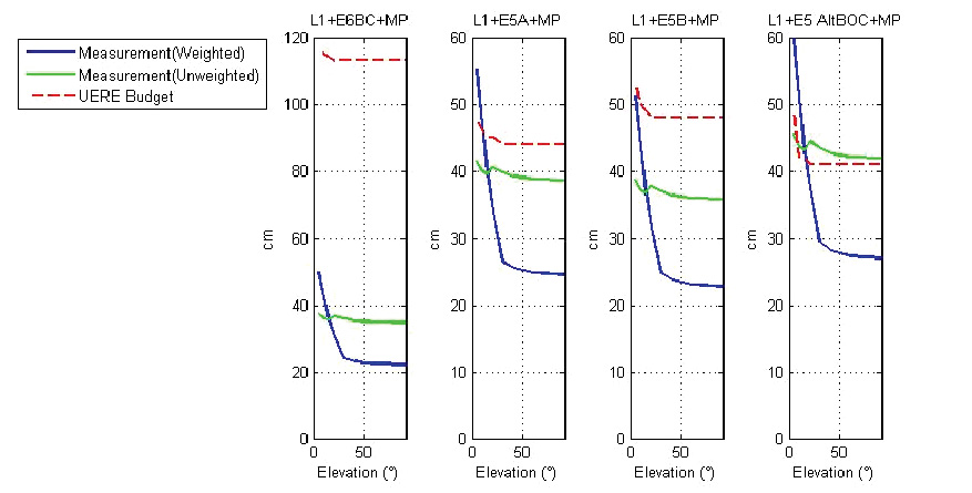
The thermal noise component of the UERE budget was measured without multipath being applied, and interference was allowed for by reducing the C/N0 by 3 dB from nominal. Separately, the multipath noise contribution was determined based on TUSREQ environments, using RFCS to simulate the multipath (the multipath model configuration was adapted to RFCS simulator multipath modeling capabilities in compliance with TUSREQ). To account for the fact that multipath is mostly experienced on the lower elevation satellites, results are provided with scaling factors applied for elevation (“weighted”), and without scaling factors (“unweighted”). In addition, following TUSREQ requirements, a carrier smoothing filter was applied with 10 seconds convergence time.
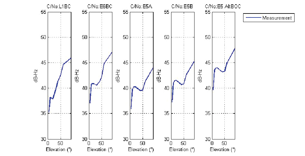
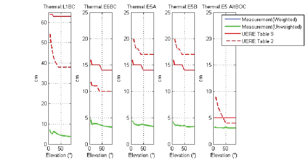
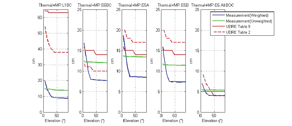
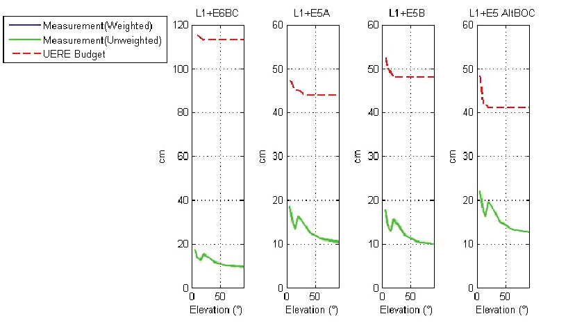
Figure 8 shows the C/N0 profile from the reference antenna with nominal power reduced by 3 dB. Figure 9 shows single-carrier thermal noise performance without multipath, whereas Figure 10 shows thermal noise with multipath. Each of these figures includes performance for five different carriers: L1BC, E6BC, E5a, E5b, and E5 AltBOC, and the whole set is repeated for dual-frequency combinations (Figure 11 and Figure 12).
FIGURE 8. Reference antenna, power nominal-3 dB, C/N0 profile.FIGURE 9. Reference antenna, power nominal-3 dB, thermal noise only, single frequency.FIGURE 10. Reference antenna, power nominal-3 dB, thermal noise with multipath, single frequency.FIGURE 11. Reference antenna, power nominal-3 dB, thermal noise only, dual frequency.FIGURE 12. Reference antenna, power nominal-3 dB, thermal noise with multipath, dual frequency.
The plots show that the thermal noise component requirements are easily met, whereas there is some limited non-compliance on noise+multipath (with weighted multipath) at low elevations. The tracking noise UERE requirements on E6BC are lower than for E5a, due to assumption of larger bandwidth at E6BC (40MHz versus 20MHz). Figures 9 and 10 refer to UERE tables 2 and 9 of TUSREQ. The relevant UERE requirement for this article is TUSREQ table 2 (satellite-only configuration). TUSREQ table 9 is for a differential configuration that is not relevant here.
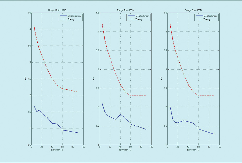
UERRE Performance. The complete single-frequency range-rate error budget as specified in TUSREQ was measured with the RFCS, using a model of the reference antenna. The result in Figure 13 shows compliance.
FIGURE 13. UERRE measurements.FIGURE 14. L1 GPS CA versus E5 AltBOC position accuracy (early test result).
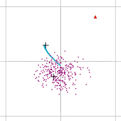
Position Accuracy. One of the objectives of the TUR-N is to demonstrate position accuracy. In Figure 14 an example horizontal scatter plot of a few minutes of data shows a clear distinction between the performances of two different single-frequency PVT solutions: GPS L1CA in purple and E5AltBOC in blue. The red marker is the true position, and the grid lines are separated at 0.5 meters. The picture clearly shows how the new E5AltBOC signal produces a much smoother position solution than the well-known GPS L1CA code. However, these early results are from constellation simulator tests without the full TUSREQ worst-case conditions applied.
FIGURE 14. L1 GPS CA versus E5 AltBOC position accuracy (early test result).
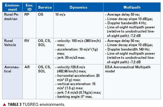
The defined TUSREQ user environments, the basis for all relevant simulations and tests, are detailed in Table 3. In particular, the rural pedestrian multipath environment appears to be very stringent and a performance driver.
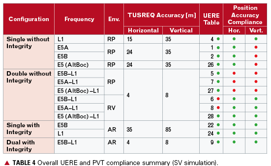
This was already identified at an early stage during simulations of the total expected UERE and position accuracy performance compliance with regard to TUSREQ, summarized in Table 4, and is now confirmed with the initial verification tests in Figure 10. UERE (simulated) total includes all other expected errors (ionosphere, troposphere, ODTS/BGD error, and so on) in addition to the thermal noise and multipath, whereas the previous UERE plots were only for selected UERE components. The PVT performance in the table is based on service volume (SV) simulations.
The non-compliances on position accuracy that were predicted by simulations are mainly in the rural pedestrian environment. According to the early simulations:
E5a and E5b were expected to have 43-meter vertical accuracy (instead of 35-meter required).
L1/E5a and L1/E5b dual-frequency configurations were expected to have 5-meter horizontal, 12-meter vertical accuracy (4 and 8 required).
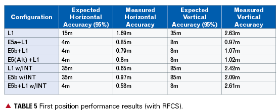
These predictions appear pessimistic related to the first position accuracy results shown in Table 5. On single frequency, the error is dominated by ionospheric delay uncertainty. These results are based on measurements using the RFCS and modeling the user environment; however, the simulation of a real receiver cannot be directly compared to service-volume simulation results, as a good balance between realism and worst-case conditions needs to be found. Further optimization is needed on the RFCS scenarios and on position accuracy pass/fail criteria to account for DOP variations and the inability to simulate worst environmental conditions continuously.
Further confirmations on Galileo UERE and position accuracy performances are expected after the site verifications (with RFCS) are completed, and following IOV and FOC field-test campaigns.
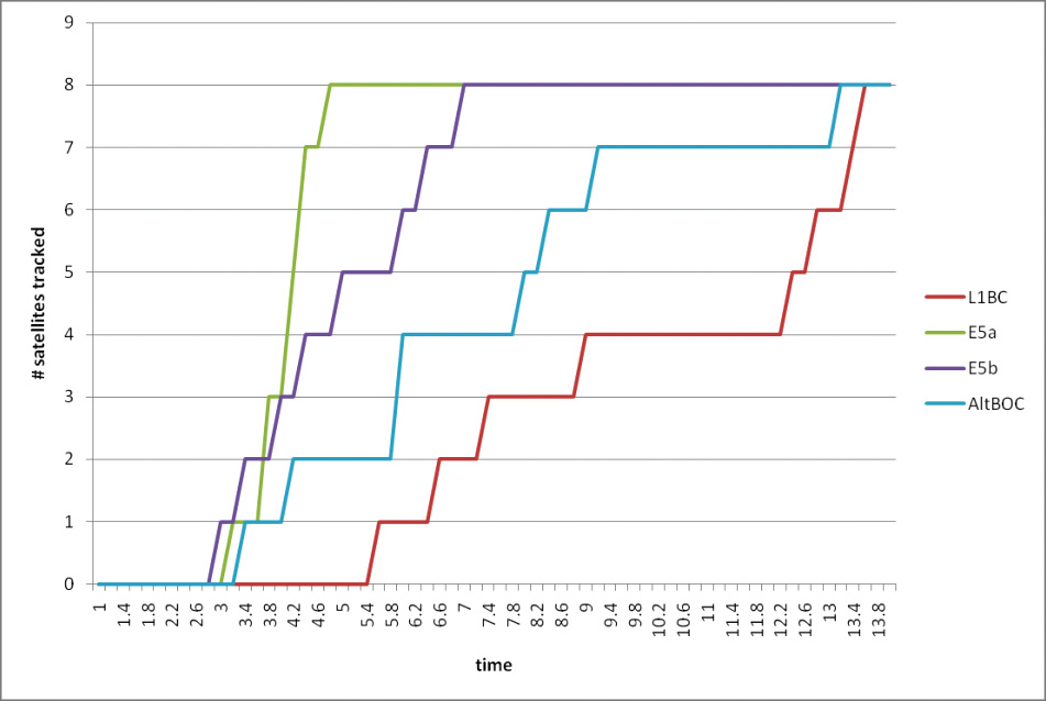
Acquisition. Figure 15 gives an example of different signal-acquisition times that can be achieved with the TUR-N after the receiver boot process has been completed. Normally, E5 frequencies lock within 3 seconds, and four satellites are locked within 10 seconds for all frequencies. This is based on an unaided (or free) search using a FAU in single-frequency configurations, in initial development test without full TUSREQ constraints.
FIGURE 15. Unaided acquisition performance.
When a signal is only temporarily lost due to masking, and the acquisition process is still aided (as opposed to free search), the re-acquisition time is about 1 second, depending on the signal strength and dynamics of the receiver. When the PVT solution is lost, the aiding process will time out and return to free search to be robust also for sudden user dynamics.
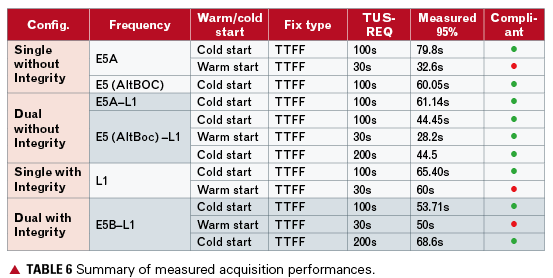
More complete and detailed time-to-first-fix (TTFF) and time-to-precise-fix (TTPF), following TUSREQ definitions, have also been measured.
In cold start the receiver has no prior knowledge of its position or the navigation data, whereas in warm start it already has a valid ephemeris in memory (more details on start conditions are available in TUSREQ). Table 6 shows that the acquisition performances measured are all compliant to TUSREQ except for warm start in E5a single frequency and in the integrity configurations. However, when the navigation/integrity message recovery time is taken off the measurement (as now agreed for updated TUSREQ due to message limitations), these performances also become compliant.
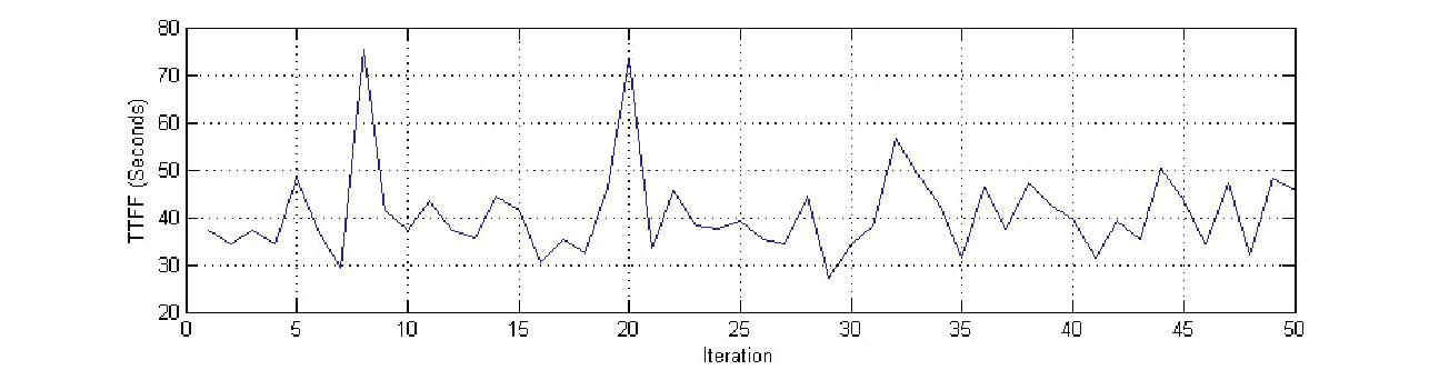
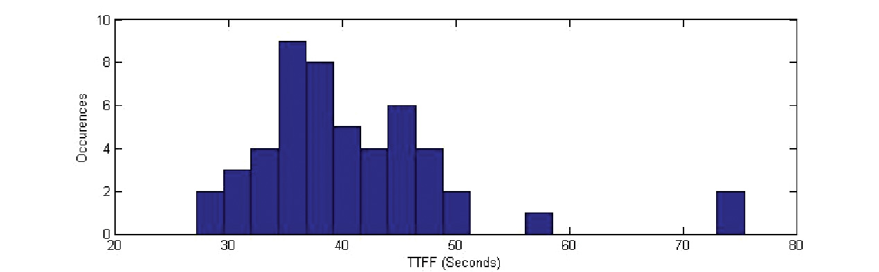
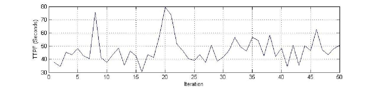
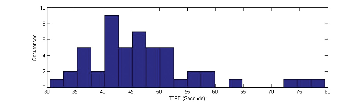
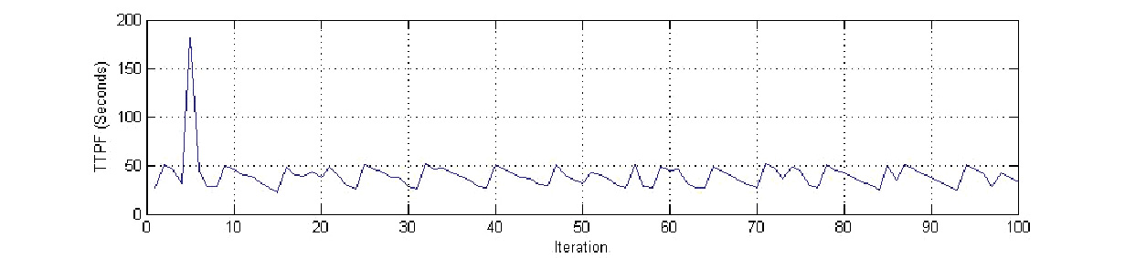
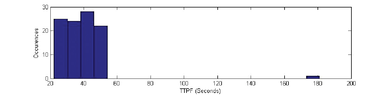
Specific examples of statistics gathered are shown in figures 16–21, these examples being for dual-frequency (E5b+L1) with integrity configuration. The outliers, being infrequent results with high acquisition times, are still compliant with the maximum TTFF/TTPF requirements, but are anyway under further investigation.
FIGURE 16. TTFF cold-start performance, dual frequency with integrity E5b+L1.FIGURE 17. TTFF cold-start distribution, dual frequency with integrity E5b+L1.FIGURE 18. TTPF cold-start performance, dual frequency with integrity E5b+L1.FIGURE 19. TTPF cold-start distribution, dual frequency with integrity E5b+L1.FIGURE 20. TTFF warm-start performance, dual frequency with integrity E5b+L1.FIGURE 21. TTFF warm-start distribution, dual frequency with integrity E5b+L1,
Integrity Algorithms. The Galileo SoL service is based on a fairly complex processing algorithm that determines not only the probability of hazardous misleading information (PHMI) based on the current set of satellites used in the PVT computation (HPCA), but also takes into consideration the PHMI that is achieved when one of the satellites used in the current epoch of the PVT computation is unexpectedly lost within the following 15 seconds. PHMI is computed according to alarm limits that are configurable for different application/service levels. These integrity algorithms have been closely integrated into the PVT processing routines, due to commonality between most processing steps.
Current test results of the navigation warning algorithm (NWA) indicate that less than 10 milliseconds of processing time is required for a full cycle of the integrity algorithms (HPCA+CSPA) on the TUR-N internal CPU board. Latency of the availability of the integrity alert information in the output of the receiver after it was transmitted by the satellite has been determined to be below 400 milliseconds. At a worst-case data output rate of 10 Hz this can only be measured in multiples of 100 millisecond periods. The total includes 100 milliseconds of travel time of the signal in space and an estimated 250 milliseconds of internal latency for data-handling steps as demodulation, authentication, and internal communication to make the data available to the integrity processing.
Conclusions
The TUR-N is a fully flexible receiver that can verify many aspects of the Galileo system, or as a demonstrator for Galileo/GPS/SBAS combined operation. It has a similar user interface to commercial receivers and the flexibility to accommodate Galileo system requirements evolutions as foreseen in the FOC phase without major design changes.
The receiver performance is in general compliant with the requirements. For the important safety-of-life configuration, major performance requirements are satisfied in terms of acquisition time and position accuracy.
The receiver prototype is currently operational and undergoing its final verification and qualification, following early confirmations of compatibility with the RFCS and with the Galileo satellite payload.