Tag: SLAM

  • Kaarta launches Stencil Pro mobile mapping system with GNSS alignment

    Kaarta launches Stencil Pro mobile mapping system with GNSS alignment

    SLAM-based mobile mapping with integrated 360° color is a rugged, geo-enabled, high-density and versatile workhorse

    Photo: Kaarta
    Photo: Kaarta

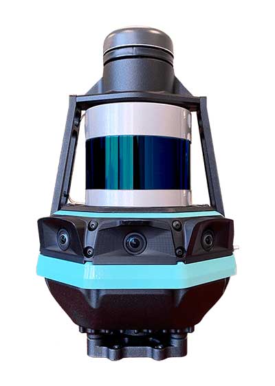
    Kaarta, an innovator of real-time mobile 3D reality capture, has announced beta testing on Stencil Pro, a versatile professional-grade mobile mapping platform with dimensional and visual fidelity.

    According to a Kaarta press release, “Whether on the road or on a job site, in a warehouse or an office, an underground mine or in the woods, along a utility corridor or a railway, the multipurpose Stencil Pro mobile mapping system is ready to take on the most challenging environments with impressive speed, providing accurate and visually stunning results.”

    An all-in-one system to scan, process and view captured data in real time, Stencil Pro offers panoramic high-definition 4K imagery and colorized point clouds. With robust surround-view perception in a wide range of light conditions, Stencil Pro is optimized for both indoor and outdoor performance.

    Featuring a 32-line high-density, low-noise lidar with a range of 120 meters (nearly 400 feet) and a data rate of 600,000 points per second, Stencil Pro produces a highly accurate 3D model in minutes.

    With an IP65 rating, Stencil Pro is safeguarded against adverse elements such as dirt, dust, fog and rain, making it the ideal tool for infrastructure mapping, mining, forestry, earthworks, construction and other harsh environments. Stencil Pro’s rugged and versatile design is adaptable to many environments, capturing data amidst poor weather, dusty work environments, and below-ground cavities or when mounted on vehicles, locomotives, ATVs and other platforms.

    Like all Kaarta systems, Stencil Pro’s simultaneous localization and mapping (SLAM) capabilities means it operates in GNSS-denied areas such as indoor, underground, under canopy, or in urban canyons. However, it is also fully geo-enabled for the many applications such as street, corridor and rail mapping where the addition of a GNSS signal is highly beneficial.

    Stencil Pro integrates the Trimble BD-990 receiver, AV-28 antenna and a range of other third-party GNSS antennas. It supports positioning accuracy enhancements through live RTK/NTRIP processing as well as PPK corrections based on data provided by the NOAA CORS network or a user-supplied base station.

    GNSS positioning data is used to align and geo-register data, providing global accuracy and further enhancing the fidelity of large area scans and long, linear scan paths. With the ruggedized design, enhanced power capabilities, as well as the option of incorporating the industry-leading SLAM accuracy in addition to – or independent of – geopositioning, Stencil Pro has the scale of traditional mobile mappers for a fraction of the investment.

    The onboard GNSS and color cameras are fully integrated into real-time capture, allowing for optimization of collected data as well as flexibility in output. The advantage of absolute positioning and accuracy coupled with 360 degree imaging technologies produces a true color, rich and robust point cloud when needed. If a colorized point cloud is not required, or GNSS is not available, reliance on other sensors is seamless.

    “Billions of dollars of commercial real estate transactions, construction projects, infrastructure maintenance and natural resource management decisions rely on understanding existing conditions data,” said Kevin Dowling, Kaarta CEO. “Obtaining up-to-date data for these environments is laborious, time consuming and expensive with current methods. Even in the most challenging scenarios, Stencil Pro rapidly provides the answers needed for managers to make informed decisions.”

    Stencil Pro is powered by either 100-240 VAC input (or 12V with an inverter) or using its two hot-swappable batteries which last for up to 3 hours of scanning. Stencil Pro’s intuitive user interface makes data capture and processing simple. The user experience includes one-button scanning, real-time scan monitoring and streamlined post-processing options for maximizing data clarity and usability. Remote operation with a touchscreen monitor allows for mounting Stencil Pro on a multitude of transports. When hand-carried, scan status can be started and stopped with the press of a button.

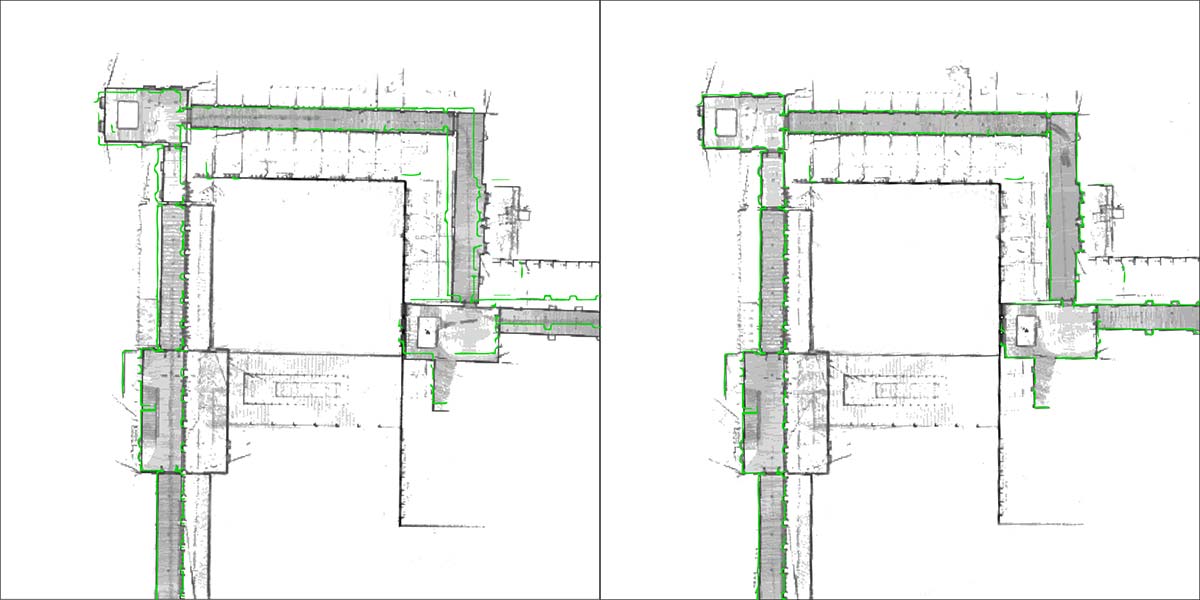
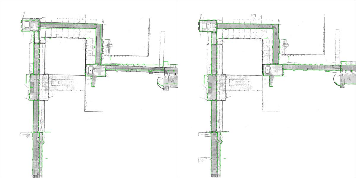
    Stencil Pro is built on Kaarta Engine, Kaarta’s patent-pending approach to solving the SLAM problem. Kaarta’s unparalleled expertise in localization – a result of its deep robotics roots – delivers definitively lower drift error than alternative SLAM systems by an order of magnitude. Kaarta’s proven technology, quality, and accuracy is trusted by AEC, geospatial, natural resource management and autonomous mobile robot professionals worldwide.

    Limited quantities of Stencil Pro will be available to ship in June. Those interested in being considered for early access to discuss a specific application, schedule a demonstration or review sample data sets can apply for the Stencil Pro Early Access Program.

  • NavVis now uses SLAM to remove point cloud artifacts

    The latest software release for the SLAM-based NavVis M6 Indoor Mobile Mapping System (IMMS) automatically detects and removes point cloud artifacts, including moving objects in static scenes, the company said.

    This image shows what an object looks like where the laser beam has hit an edge, before and after the algorithm has been applied. (Image: NavVis)
    This image shows what an object looks like where the laser beam has hit an edge, before and after the algorithm has been applied. (Image: NavVis)

    NavVis is a global provider of indoor spatial intelligence solutions. The latest IMMS release removes artifacts from point clouds during the post-processing of scan data.

    Fringe points and dynamic objects are two common types of point cloud artifacts that affect all 3D laser scanning devices. Fringe points arise when a laser beam hits the edge of an object as well as its background. This scattered beam ultimately appears as a “fringe” around the edge of the object in the point cloud.

    The second type of point cloud artifact results when dynamic objects, such as humans walking through a scan, are captured by the laser scanner and then appear as artifacts in the point cloud.

    A point cloud before and after the algorithm has been applied to a dynamic object. (Image: NavVis)
    A point cloud before and after the algorithm has been applied to a dynamic object. (Image: NavVis)

    According to the company, the NavVis M6 IMMS is a simultaneous localization and mapping (SLAM)-based system that uses laser scanners to capture a high volume of measurement points of an environment. As SLAM-based mobile mapping systems move through the environment while scanning it, objects are observed from multiple different angles and positions.

    With the latest software update, the algorithms applied during the post-processing of scan data use those multiple observations to detect whether measurement points actually exist in the physical space. If it is determined that the point does not exist and is instead resulting from the laser beam hitting an edge or an object moving through the space, this point is automatically removed.

    The result is a much cleaner, crisper point cloud that requires less clean up time in point cloud editing software and that is easier to use for applications such as BIM modeling, the company said.

    “We have been working hard to develop a very precise SLAM technology that significantly improves the quality of point clouds captured by a mobile device,” said Georg Schroth, NavVis co-founder and CTO. “As this latest software feature shows, SLAM offers a lot of potential for laser scanning and AEC professionals who are looking for technology that not only speeds up the capture of data but also delivers high quality point clouds. We see a lot of potential in this technology and look forward to sharing future innovations.”

  • Expert Opinions: How can we make autonomous cars safe?

    Expert Opinions: How can we make autonomous cars safe?

    Q: How can positioning technology ensure safety for passengers of autonomous cars and for others on or near the roadway?

    Paul Perrone, Founder/CEO, Perrone Robotics


    A:
    Satellite-based and local beacon-based positioning technologies offer the best opportunity for reliable and precise location determination of an autonomous vehicle. Alternate solutions like SLAM and lane keeping are decent augmentations, but suffer from the imprecision that comes from sensing in a large dynamic environment. As satellite and local beacon-based positioning technologies become increasingly more pervasive and accurate, this will continue to yield the most reliable and deterministic solution for safe localization of autonomous vehicles.


    Paul Groves, Senior Lecturer, University College London

    A: No matter how good it gets, positioning technology can never ensure the safety of autonomous car passengers and pedestrians. Knowing the position of each car is insufficient; you need to know where everything else is, including children, animals and temporary construction barriers. It is simply not practical to fit everyone and everything with a positioning device that transmits to every nearby vehicle. Collision avoidance therefore needs sensors such as radar and lidar.


    Zoltan Molnar, Functional Safety Manager, NovAtel

    A: Realization of safe autonomy requires the establishment of layers of protection using safety mechanisms without dependent faults. Absolute position provided by precise GNSS and inertial technology provides an independent reference for truth test of positioning solutions obtained with vision-based technologies. Vision-based solutions may incorporate common cause faults like sight obstruction, processing algorithms or similar. Absolute positioning can also contribute to realize near-real-time updated maps.

  • NavVis launches 6D SLAM indoor mapper

    NavVis-M6-indoor-mapper-WMapping company NavVis has launched the M6, a next-generation indoor mobile-mapping system that the company says can overcome the scalability and data quality constraints of reality capture technology.

    Surveyors and architecture, engineering and construction (AEC) professionals can now use reality-capture technology for large-scale indoor mapping projects. The M6 can be used for factory planning and creating and updating as-built BIM (building information modeling) models and construction monitoring.

    The NavVis M6 is an all-in-one system that captures 360-degree immersive imagery, photorealistic point clouds, Bluetooth beacons, Wi-Fi signals and magnetic field data.

    The NavVis M6 features a mobile lidar system that lets it scan up to 30 times faster than stationary devices, letting users capture up to 30,000 square meters in a day.

    Cutting-edge 6D simultaneous localization and mapping (SLAM) technology significantly improves the quality of data captured. Thanks to 6D SLAM, M6 continuously scans even complex indoor environments, including uneven surfaces or changing elevations such as ramps, open spaces or long corridors without compromising the quality of the data.

    M6’s innovative software is complemented by hardware features designed to improve the quality of data and ease of capture: four laser scanners with a range of up to 100 meters are arranged to maximize scan coverage, while six cameras automatically take high-resolution images during mapping. The innovative design of the M6 includes camera placement that keeps the operator in a blind spot.

    NavVis IndoorViewer software gives stakeholders access to the scanned environment through an interactive virtual building in their browser.

    “The NavVis M6 marks a quantum leap in indoor mobile mapping,” Felix Reinshagen, CEO of NavVis. “Anyone who needs to scan large properties, run repeated scans or would like to move into the field of reality capture will profit from the groundbreaking data quality.

    “With M6, users can now quickly capture large, complex indoor environments for typical tasks such as updating floorplans, documenting construction progress or creating as-built BIM models. At the same time, M6 captures the data needed to provide customers with additional deliverables such as browser-based immersive walkthroughs and indoor navigation,” Reinshagen said.

  • Signals of opportunity: Holy Grail or a waste of time?

    The military is always looking at new techniques and technology for deriving position and, it seems, every few years signals of opportunity (SOOP) becomes fashionable again.

    In broad terms, SOOP refers to the use of any signals for navigation, which are not normally intended for navigation. This might mean TV or radio broadcast signals, cellular network signals, or anything else you can receive.

    Figure 1. Navigating using opportunistic signals, such as phone, TV and radio transmissions. (Image: Michael Jones)

    The promise of SOOP

    In the quest for resilient positioning and navigation, SOOP certainly sounds attractive. When GPS goes down, why not simply continue to navigate by receiving digital TV signals instead? Why not receive a whole pile of different signals, and make yourself virtually immune to jamming?

    You can even turn jamming from a problem to a solution. If someone does decide to turn on a bunch of jammers, why not use the jammers themselves as signals of opportunity, and position yourself using those? With so many possibilities, it’s no wonder SOOP excites people. Certainly it’s of great interest to the military of many countries.

    Let’s dip our toes into the world of opportunistic navigation.

    What signals might we use?

    The figure below shows what we get if you use a spectrum analyzer to quickly sample what’s on the airwaves in the UK, in this case looking fairly coarsely from 10 MHz to 3 GHz. A number of candidate signals immediately present themselves, which are labeled 1 to 11 and identified in the table.

    Figure 2. Plenty of opportunistic signals are out there. (Image: Michael Jones)

    There are, of course, many more signals-of-opportunity out there, but this illustrates a few of the more visible ones. How do we go about using these signals for positioning ourselves?

    Bringing in defense techniques

    For decades, one of the principle requirements in electronic warfare (EW) has been to geolocate enemy transmissions. This has given rise to a plethora of techniques for determining location, such as received signal strength (RSS), angle-of-arrival (AOA), time-of-arrival (TOA), time difference of arrival (TDOA), frequency difference of arrival (FDOA), and so on.

    In a positioning application, we have the reciprocal problem: instead of trying to geolocate a transmitter relative to ourselves, we are trying to geolocate ourselves relative to a set of transmitters. But of course we use the same techniques: GPS is an excellent example of a TOA system.

    Let’s look at the basics of TDOA. A signal s arriving at location 1 can be expressed as

    where A1 is an amplitude scaling to account for attenuation over the path, n1 is additional noise, and d1 is the signal delay time. We can repeat the equation for further locations:

    Usually we designate one location as the reference, in which case we can rewrite the above equations as:

    The first problem is to determine D, the time difference of arrival. There are many ways to do this, but a popular method is to perform generalized cross-correlation:

    Or, in a realizable digital form:

    Finding the peak of this function gives us our estimate of the time difference D. It’s a little bit more involved in practice, as we would normally apply filtering functions to improve the TDOA resolution, but you get the idea. Each TDOA measurement gives a set of possible locations that form a hyperboloid. With three stations, we will have two hyperboloids, the intersection of which gives a set of possible locations along a hyperbola. The addition of a fourth signal allows us to plot three hyperboloids, from which we can then determine position.

    Figure 3. Positioning using TDOA involves solving for the intersection of hyperboloids. (Image: Michael Jones)

    There are various ways to solve for the hyperbolic intersections. With only four measurements it is possible to compute the solution analytically, but with many measurements an iterative approach or minimum mean squared error technique is often used.

    TDOA, when used properly, can form the basis of a highly accurate positioning system. A number of navigation systems utilize TDOA technology, such as LORAN and its variants.

    Now let’s consider angle-of-arrival. AOA techniques generally make use of an antenna array to provide spatial diversity, allowing the direction of a source transmission to be determined. Measured angles to multiple transmitters then allows triangulation to be performed and the position computed. There are some advantages to AOA techniques, when compared to TDOA: position can be computed with as few as three signals, there is no requirement for time synchronization in any form, and narrowband signals can be used without loss of accuracy. Disadvantages include larger physical size due to the use of an array of antennas, and potentially more susceptible to environmental effects such as multipath.

    Classical AOA methods include Capon’s method, but since the 1980s the preferred techniques have often been signal subspace methods such as Multiple Signal Classification (MUSIC), Estimation of Signal Parameters by Rotational Invariance Techniques (ESPRIT), and variants of these techniques. The most well known of the subspace methods, MUSIC, performs an eigendecomposition of the sample covariance matrix given by:

    Once the signal and noise eigenvectors have been separated the array manifold is projected into the appropriate subspace to yield the MUSIC surface:

    The peaks of the function P, give us the direction-of-arrival of any signals. From these multiple lines of bearing we can perform triangulation, and derive our position.

    We’ve looked at TDOA and AOA methods, which are just two of many techniques that can be used to process signals-of-opportunity to derive position. But there are some perceived drawbacks to navigation by SOOP. By definition, SOOP makes use of transmitters that are uncooperative, and not generally designed with navigation in mind.

    For TDOA you are dependent on signals that are transmitted synchronously (or else you need a separate source of reference), which may or may not be the case. You also need to know the locations of the various transmitters, for example the coordinates of any GSM base stations, digital TV transmitters, and so on. It may be difficult to obtain this information, especially in some parts of the world. But whilst it certainly helps to have this information, it isn’t entirely necessary. It is possible to both position yourself, and build up a map of the transmitter locations, without a-priori information.

    SLAM

    Simultaneous localization and mapping (SLAM) is a field popular in the autonomous vehicle and robotics communities. It’s often described as a machine-learning concept, which aims to solve the problem of positioning oneself within a map, whilst simultaneously constructing and updating that map. There are a pile of techniques and algorithms that have been applied to the problem, including the good old Kalman filter, and the particle filter.

    In basic SLAM, you use a state vector to store an estimate of your position (and often orientation as well), just as you would in a typical GPS receiver. However, in SLAM, we also store estimates of the transmitter positions (called “features” in SLAM terminology). If we want to localize ourselves in a global coordinate frame it does mean we need an initial estimate of our position from some other means, like GPS. Otherwise we can only localize ourselves within the map we are generating.

    From our initial position estimate, we then move in some way. We then estimate our position again, perhaps using some form of dead reckoning technique, like inertial or visual odometry. Together with our motion model, this forms the prediction phase of the Kalman filter. We perform the measurement phase by re-measuring any features (our transmitters of opportunity), along with any new ones.

    Figure 4. Basic SLAM concept: simultaneously estimate the locations of both the vehicle and the transmitters of opportunity. (Image: Michael Jones)

    If you know about Kalman filters, you might spot one of the problems with SLAM: As the number of features increases, the size of the state vector becomes larger, until you end up with huge matrices that are very time-consuming to solve. The solution time is a quadratic function of the number of state variables. For this reason, it is often necessary to constrain the problem in some way: perhaps by limiting the number of transmitters we keep track of.

    But when done properly, SLAM is a powerful technique for signals-of-opportunity navigation.

    Is SOOP worth it?

    We’ve seen that, by using a variety of techniques, almost any radio signal can be used for opportunistic navigation purposes.

    One disadvantage of SOOP is that it can require complex hardware to do it well. If you truly want to use all the opportunistic signals out there, then you need a receiver that can handle a very wide range of frequencies. You also need an antenna or set of antennas that can do the same.

    When resilient PNT is a critical military requirement, you cannot afford to rely on signals that you don’t control. SOOP is also highly dependent on where you are. There aren’t many opportunistic signals at sea or in the desert, compared to in the urban environment (perhaps the odd satellite signal, or HF signal).

    So SOOP is unlikely to become a primary technology for the military. But it does have the potential to be a powerful augmentation to GNSS, and it certainly deserves a place in the PNT kit bag.


    Figures: Michael Jones

  • NavVis improves SLAM precision indoors

    NavVis, a mobile indoor mapping, visualization and navigation company, released new mapping software that significantly improves the accuracy of simultaneous localization and mapping (SLAM) technology in indoor environments, such as long corridors, the company said.

    The software update will be available for users of the NavVis M3 Trolley and will significantly improve the accuracy of the resulting maps and point clouds. NavVis’ mobile mapping system, the M3 Trolley, builds upon SLAM to increase speed and efficiency when scanning buildings.

    The images below demonstrate the impact of NavVis Precision SLAM technology. The left image depicts a long corridor mapped with a conventional SLAM system where the above-mentioned drift error has occurred. The green outline shows how the map deviates from the true structure. The image on the right shows the significantly improved map accuracy obtained when mapping the same area using the M3 Trolley with the new Precision SLAM technology.

    Image: NavVis
    Image: NavVis

    Here is a closer look:

    Image: NavVis
    Image: NavVis

    SLAM is a technique originally developed by the robotics industry that is now increasingly being used in surveying and autonomous driving technologies. It solves a core problem that long plagued robotics engineers by enabling a device to determine its location while simultaneously mapping an unknown environment. This is done by chaining millions of measurements into a trajectory estimate.

    However, even when a device captures highly accurate individual measurements, chaining them will result in an accumulation of noise and tiny measurement uncertainties. Over time, the estimated motion will start to deviate from the true motion (drift error). This can often be observed as a slight bending of long corridors that are actually straight. All available SLAM systems — regardless of whether these use LIDARs or other sensors — are inherently affected by this phenomenon.

    The NavVis Precision SLAM technology significantly reduces drift error and improves the SLAM accuracy. This is particularly evident in cases where complementary techniques such as loop closures cannot be deployed, if, for example, the building’s layout does not allow for it.

    Precision SLAM even improves accuracy when SLAM anchors are used to incorporate ground control points into the mapping process.

    “I am very excited about our new Precision SLAM technology,” said Stefan Romberg, head of mapping and perception at NavVis. “We are always striving for the highest possible map and point-cloud accuracy and improving SLAM is a critical component to being successful. It is widely known among SLAM developers and users that complementary approaches such as loop closures or ground control points are needed to achieve a high accuracy.

    “However, with the Precision SLAM technology we have developed an approach that not only nicely complements the former techniques but is especially evident when these have little effect or cannot be used.”

  • Research Online: Multi-sensor SLAM key to tactical situational awareness

    Rescue and military applications require rapid, accurate and reliable information about unknown environments.

    Simultaneous Localization and Mapping (SLAM) is a key technology for providing an accurate and reliable infrastructure-free solution for indoor situational awareness.

    The researchers’ approach is to integrate a monocular camera, multiple inertial measurement units (IMUs), a barometer and a ranging sensor to obtain a solution for SLAM, as well as tactical motion information, such as detecting whether a rescue person or a soldier is running or crawling.
    In their paper, the authors discuss a particle filter implementation for integrating measurements from visual perception, a foot-mounted IMU, a barometer and sonar.

    The method developed is tested via experiments done in an office environment. Test setup and results are discussed in the paper.
    The results obtained using the developed method are anticipated to show improvement on the accuracy and reliability of monocular SLAM compared to previous methods.

    The proposed data fusion approach is expected to yield a vertical accuracy sufficient for floor identification in the test environment without utilizing Wi-Fi or other local infrastructure.

    The method is anticipated to advance the state of the art in infrastructure-free SLAM solutions based on a monocular camera.

    Also, the research will make significant progress towards a functioning infrastructure-free situational awareness system, which is desperately needed in the application areas in question.

    By Laura Ruotsalainen, Martti Kirkko-Jaakkola, Liang Chen, Simo Gröhn, Robert Guinness, Heidi Kuusniemi, Finnish Geospatial Research Institute (FGI), National Land Survey of Finland.
    Presented at ION International Technical Meeting 2016.


    Miniature Atomic Clocks

    “Enhanced Quantum Miniature Atomic Clock (MAC) Performance and Applications,” by Paul R. Gerry III, Will Krzewick, John Malcolmson, Microsemi.
    Microsemi has been developing small form factor atomic clocks for several years. These products have smaller size, lower power and higher performance than traditional atomic clocks.

    The recently enhanced Quantum Miniature Atomic Clock (MAC) is a small-size high-performance atomic clock with low power and low weight enabling a new range of applications previously not possible. The paper discusses the MAC performance, the performance grades and some of the applications that the MAC enables.

    Presented at the Precise Time and Time Interval (PTTI) Meeting, co-location with ION-ITM 2016.