TerraGo has released TerraGo Edge 3.9.3, which features full support for OGC GeoPackage, a universal format for sharing maps and geographic data across mobile devices and all platforms.
TerraGo Edge enables users to import and export OGC GeoPackage as a SQLite database optimized for performance on iOS and Android devices.
“Because we listened to our customers, we designed TerraGo Edge from the ground up to be an open solution for exchanging field engineering, GIS, GPS and asset management data across vendor platforms and devices,” said John Timar, vice president, Worldwide Sales at TerraGo. “GeoPackage is an important win for customers because it’s a dramatic shift away from proprietary formats and technology. GeoPackage breaks through user dependence based on vendor data lock-in, enables platform-independent data exchange and refocuses customer value on software features and performance.”
The latest TerraGo Edge 3.9.3 release closes the loop for a complete GeoPackage collaboration workflow by allowing Edge app users to import GeoPackage data from a mobile device, collect location-tagged field data and roundtrip the information back to the GIS or other enterprise systems of record.
BYOD GPS Gets Real: Lessons Learned with the New Rules of GPS Data Collection
Thursday, April 14, 1 p.m. ET / 10 a.m. PT
In this GPS World webinar, join us as we examine how five organizations from five industries (oil & gas, engineering, water utility, transportation and natural resources) made the switch from GPS handhelds to smartphones and tablets for their field data collection needs. Speakers are Michael Gundling and David Basil, TerraGo.
Version 3.9.3 features these enhancements:
Advanced GIS Integration
Deliver GeoPackage data to any TerraGo Edge mobile app user
Create offline map when GeoPackage is embedded in a GeoPDF
Simultaneously import GeoPDF and GeoPackage data back to Edge server
Improved Mapping Experience with EdgeMap Optimizer
Automatic detection of best resolution (DPI) for offline maps upon import by mobile user
Manually select the optimal resolution upon import
Data collection enhancements with the New Form Template Selection, including a new search function in form fields to improve user productivity and data integrity.
A GPS World webinar on April 14 explores how five organizations made the switch to using their own tablets and smartphones for field data collection (also known as bring your own device, or BYOD).
Lance Fugate of Enmapp based in Calgary inspects pipelines using TerraGo Edge on iPads.
Webinar participants will learn about and benefit from the real-world challenges faced during the five deployments of BYOD GPS field data-collection solutions. These customers and projects span very different industries, working conditions and requirements for GPS field data collection. Each offers a unique perspective based on their requirements and ultimately their approach to using smartphones and tablets for GPS-powered asset inspections, surveys, field service and remote workforce management.
The City of Sebring Water Utility faced challenges with field crew use of CAD diagrams, as well as obtaining RTK accuracy on iPads. Read more about the Sebring project in this article from our March issue.
The State of Louisiana needed to complete more than 4,000 miles of annual levee inspections while syncing field data from tablets to the cloud. Read more about the project.
Kleinfelder engineers needed to shift to real-time GPS on tablets so they could eliminate four hours per day of post-field processing, and bring projects in faster and under budget.
Empire Electric needed a method for customers to approve GPS-tagged work orders in real-time from the job site to avoid delays and lower costs.
Enmapp needed to cut pipeline inspection hardware and labor costs in the face of the oil industry’s low-price and margin-challenged cost environment.
Woolpert has signed a five-year, multimillion-dollar Geospatial Product and Services Contract 3 (GPSC 3) with the U.S. Geological Survey (USGS) to provide mapping and surveying services.
The GPSC is a suite of contracts used by federal, state and municipal government entities to partner with USGS for the purpose of fulfilling their geospatial data requirements.
The contract will be administered through the National Geospatial Technical Operations Center (NGTOC) in an effort to obtain geospatial data services throughout the United States and its territories. The contract also will be used to support the 3D Elevation Program (3DEP) and used by other federal, state and local agencies.
“This provides Woolpert with the opportunity to continue working with USGS on their 3D Elevation Program (3DEP), an eight-year program to provide highly accurate 3D elevation data of the entire U.S.,” said John Gerhard, Woolpert project director. “This data will be collected via lidar (light detection and ranging) to create the most accurate surface model, and will be used to evaluate flood risk and natural resources, support FEMA, help farmers with precision agriculture, assess and manage infrastructure, and much more.”
Jeff Lovin, Woolpert senior vice president and director of government solutions, said the Woolpert staff is proud to have had the opportunity to work with the USGS for nearly 25 years. “Over those 25 years, we’ve had the opportunity to collaborate on different layers of the National Spatial Data Infrastructure (NSDI), from the development of nationwide imagery in the 1990s to 3D elevation and hydrography today,” Lovin said.”It’s very gratifying to have the opportunity to play a part in such an important program for our nation.”
Hemisphere GNSS has released the S321, its next-generation multi-frequency, multi-GNSS survey smart antenna. The S321 — designed for land or marine survey — combines Hemisphere’s Athena and Atlas technologies with a new web user interface offering customer-friendly performance.
For professional marine applications — such as marine construction, hydrographic surveying or dredging — using the S321 with Athena RTK (real-time kinematic) enables users to achieve impeccable results and maintain peak up-time, the company said. The ruggedized antenna was designed for demanding and challenging environments and meets IP67 requirements.
The S321 smart antenna by Hemisphere GNSS.
“The S321 is another example of how much Hemisphere has changed,” said Chuck Joseph, president and CEO. “A fantastic survey smart antenna with industry-leading RTK, connectivity, and management capabilities, the S321 offers unbeatable performance and value to the industry.”
Athena RTK
Athena excels in environments where high-accuracy GNSS receivers can be used. Hemisphere’s customers have tested and proven Athena’s performance in long baseline, in open-sky environments, under heavy canopy, and in locations experiencing significant scintillation.
Initialization time – Reliably consistent initialization performance, while at the same time performing initializations in less than 15 seconds at better than 99.9 percent reliability.
Robustness in difficult operating environments – Extremely high productivity under aggressive geographic and landscape-oriented environments for GNSS.
Performance on long baselines – Position stability for long baseline applications.
Performance under scintillation – Sustained accuracy under ionospheric scintillation activities.
Atlas GNSS Global Corrections
The S321 ships preconfigured to test drive corrections from Hemisphere’s Atlas global corrections service. The bundled solution provides users worldwide with an easy way to use Atlas, including the worldwide H10 service offering 8-centimeter, 95-percent accuracy (4 cm RMS).
Network RTK Augmentation
BaseLink technology allows Atlas-capable receivers like the S321 to self-calibrate, self-survey, and automatically manage the transmission of RTK correction data to augment or extend established or new GNSS reference networks in areas of poor Internet connectivity.
The S321 introduces Hemisphere’s aRTK technology. Powered by Atlas, aRTK enables the S321 to operate with RTK accuracies when RTK corrections fail. If the S321 is Atlas-subscribed, it will continue to operate at the subscribed service level until RTK is restored.
The S321 also introduces SureFix, Hemisphere’s new processor running in combination with Athena to provide high-fidelity RTK quality information that results in guaranteed precision with virtually 100 percent reliability.
Features:
Athena RTK engine
GPS, GLONASS, BeiDou, Galileo, QZSS
372 channels
Atlas corrections delivered via L-band and over the Internet
Wireless connectivity via Bluetooth and Wi-Fi
Powerful web user interface
Two versions (Each can be configured as Base or Rover):
UHF + GSM / WCDMA
GSM / WCDMA (Network Rover)
4 GB internal memory card and 64 GB-capable MicroSD card for data logging, download and upload.
The S321 can be ordered now and is available to ship before the end of the month.
The S321 is making its tradeshow debut at Oceanology International 2016 at ExCeL, London, UK, March 15-17, at booth G500.
For more information about the S321, Athena, Atlas, or its other advanced features, please call +1 (844) 217-2845 (within Canada / USA only) or +1 (480) 291-6766, or email [email protected].
In February, I hit the 10-year mark with GPS World magazine. That milestone caused me to stop and reflect on all the changes in my work over the past decade.
In 2006, our web presence was mostly taking the print magazine and replicating it on the website, complete with a Table of Contents for the current issue. We had dozens of categories and subcategories, slicing and dicing the industry into micro-segments. I found it increasingly difficult to decide which category to place stories into, because so much research and so many products have multiple applications.
We’ve now greatly simplified the categories, but they still overlap. A Mobile story will touch on Transportation and OEM. A Survey story is also a Mapping story. A UAV story has applications for Defense or Mapping. Because of this, I invite you to see our categories as a jumping off point, not as independent silos. Peruse all the pages of our magazine — you may be surprised at what you find.
Another massive change over the past decade is our way of thinking. GPS World is no longer just a monthly print magazine with a now-and-then web story or editorial. We are the major industry web presence, with almost 1.5 million page views annually.
In 2006, I spent perhaps 20 percent of my time on the website. Today it’s closer to 80 percent.
In many ways, I have gone back to the early days of my career as a daily newspaper journalist to post news every day on both gpsworld.com and our sister Geospatial Solutions website. You can easily tap into these news streams through Twitter (which, coincidentally, is celebrating its 10th anniversary this month.)
I’m looking forward to another 10 years with GPS World, and I hope you come along for the ride.
Trimble has added a new scalable GNSS receiver to its geospatial portfolio. The Trimble R9s GNSS receiver is scalable and flexible. Built on a sleek, modular GNSS platform, geospatial professionals can add functionality according to their workflow demands, such as being deployed as an RTK base station or an RTK rover mounted on a rod, in a backpack or on a vehicle.
The Trimble R9s GNSS receiver provides access to multiple GNSS constellations, wide-band 450 MHz internal radio, Ethernet connectivity and is easily configurable via the front panel. The solution also offers scalability from an entry-level receiver for post-processing, to a full-featured triple-frequency GNSS base and rover.
The R9s also supports corrections services, including Trimble CenterPoint RTX (better than 4 centimeters delivered via L-band satellite) and enhanced xFill technology, which allows surveyors to continue collecting data with centimeter-level accuracy indefinitely when RTK or VRS connectivity is lost.
Options such as Trimble Access field software, Trimble DL Android app and Web user interface or front panel allow the receiver to be configured for optimal performance to support a broad range of survey workflows.
An Australian company that manufacturers GNSS echo sounders aided the aiders — leading a medical ship through uncharted waters in Papua New Guinea.
The CEESCOPE echo sounder enabled the ship to reach volunteers who were working to save the life of a newborn.
The ship, operated by YWAM Medical Ships Australia (YWAM MSA), visits remote villages in Papua New Guinea, giving communities access to life-saving medical and dental services. The village locations are accessed by river, and while often there is adequate tide information to help navigate, there are no available charts or bathymetry data for the passages upriver.
Without a navigable route to follow, the medical ships simply could not travel to locations where help is needed the most.
To solve this problem, YWAM decided to make its own charts, with help from CEE HydroSystems. Using a small, fast launch equipped with a CEESCOPE single-beam echo sounder and GPS hydrographic survey system, YWAM volunteer and master mariner Jeremy Schierer set out to find safe routes through vast river deltas ahead of the medical ship.
While surveying at high speed to maximize the area covered, Schierer executed reconnaissance patterns along the river while continuously updating the hydrographic survey plan based on the results seen.
Survey data gathered and processed in HYPACK acquisition software were exported to the navigation system of the ship to provide waypoints marking the safe passage route along the river. Used with available and observed tide data, the navigator of the vessel could confidently travel upriver without the risk of grounding.
The CEESCOPE is a one-box survey system that can be swapped between the two available 4.2-meter and 5.2-meter boats. It can be used without an acquisition PC on the survey launch if needed — all data recorded on the internal memory, and can run on its own battery power for an extended duration. With operation in remote areas on small boats, reliability and usability were key for YWAM.
YWAM also used the CEESCOPE with HYPACK from the wheelhouse to navigate the ship along the surveyed routes on custom electronic charts.
In the third year of YWAM’s operation in Papua New Guinea, Schierer recorded a staggering 3,400 kilometers (2,000 miles) of bathymetry to help navigate the Pacific Link. All of the rivers were uncharted before the ship traveled upstream. With incomplete tide-station coverage, determining the ship’s path was a complex calculation. Despite this, and complicated by a bore tide, YWAM was able to take its vessel 75 kilometers upstream in the Bamu River, Western Province, without published charts.
However, the most startling example of the benefit of the YWAM hydrographic survey approach took place in the second year of operation.
“Baimuru is up the Pie River from Port Romilly in the Gulf Province,” Schierer said. “The only previous known route took us about four hours through the rivers and required high tide and daylight.
“We went out with the CEESCOPE to see if we could find an alternate and more direct route to the open sea. We left the ship just before sunrise and went as far as 8 nautical miles off the coast to confirm a good passage — and we found one that was deep enough.”
Instead of leaving when scheduled, the ship received an emergency call from the medical center about 300 meters away on the shore, where there is no electricity or running water.
“A lady had just given birth, and they were requesting attendance by our doctor and midwife. Evidently the baby was born in the canoe on the way to the medical center, and for some time the baby lay in the bottom of the canoe.
“By the time we unsecured our small boat and got the medical team ashore, the baby was 35 degrees Celsius and not warming up. Our medical team was able to assist in warming the baby and reported that if we had not been there, they were quite certain that the baby would not have survived the night.
“The only reason we were still there was because we had the CEESCOPE and had been able to find another route. We’ve charted more than 1,200 kilometers with the CEESCOPE so far, and it is making a huge difference,” Schierer said.
The track of the medical ship on the previously uncharted Bamu River.
Based in Sydney, CEE HydroSystems opened an office in San Diego, California, in late 2015, to serve the United States and Canada. The company specializes in RTK GNSS-enabled precision shallow water hydrographic echo sounders. Its products are aimed at surveyors conducting shallow water bathymetric surveys.
“For inshore hydrographic surveys of water bodies such as canals, lakes, rivers or industrial water impoundments, survey firms inexperienced in hydrographic methods often have to resort to conventional and laborious processes using sounding lines, range poles or basic sonar equipment,” said Peter Garforth, CEE HydroSystems managing director. “Our CEESCOPETM survey system puts a RTK GNSS solution and precision echo sounder into a compact single package, allowing surveyors to vastly improve productivity on these surveys.”
The CEE range of echo sounders with GPS was first developed to offer surveyors a one-box solution to reduce hardware setup time and the need for interconnecting components.
Portable echo sounder
The CEESCOPE uses a built-in RTK GNSS receiver and UHF radio modem to acquire RTK-quality position and elevation that is used in hydrographic surveying software to output xyz point-cloud data files of bottom elevations in local coordinates and datums. In RTK mode, the CEESCOPE can be directly connected to the local UHF base station radio. The internal CEESCOPE GNSS receiver provides accurate position data at 1–20 Hz, and the single-beam echo sounder records soundings at up to 20Hz.
Both data streams — plus any ancillary measurements fed into the unit such as heave, pitch and roll — are precisely time-tagged using a 1PPS signal and then recorded on the CEESCOPE internal memory. Simultaneously, the data are output to an acquisition PC or tablet.
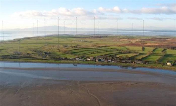
eLoran Antenna Park of 13, 200-meter masts at Anthorn, UK.
Readers of GPS World, its e-newsletters, website — and all interested PNT parties — are invited to register their opinion in the current poll at gpsworld.com/janpoll.
Should the U.S. government install a full eLoran network of broadcast stations to back up GPS in case of jamming, interference or other emergencies?
Yes.
No.
More study is needed before answering this question.
Don’t know.
Voters may enter their name in a drawing to receive a $50 gift card. Vote by Jan. 11, 2016.
Results will be published in the February issue of GPS World magazine.
Leica Geosystems has introduced two new additions to its Leica GeoMo deformation monitoring solution: Leica GeoMoS AnyData and GeoMoS API.
Users of the system can now create comprehensible visualizations and customizable reports, which enables powerful sensor data fusion for applications, such as air or water quality monitoring and construction or building management.
With GeoMoS AnyData and GeoMoS API, multiple open interface standards are accessible to provide even more information to projects than just classic geodetic monitoring applications, according to a news release from Leica. The open solution offers flexibility; it is capable of automatically acquiring, processing and distributing intelligent information locally or via the Internet in real time.
Leica GeoMoS integrates, processes and distributes all project data within one software program.
“Monitoring professionals are confronted daily with vast amounts of data collected and provided by a variety of sensors,” said Michael Rutschmann, senior product manager of Structural Monitoring at Leica Geosystems, in the news release. “With these additions to Leica GeoMoS, all information is now easily accessible via web-based visualisation. This is absolutely the most efficient way to convert raw data streams into intelligent information for any user.”
Routescene has jointly developed with Hanseatic Aviation Solutions an integrated fixed-wing UAV and LidarPod solution for surveying.
Following in-depth customer research, Routescene identified a gap in the market for an unmanned aerial 3D mapping solution capable of flying long distances, particularly for use in large countries with great expanses of remote land such as Australia, the United States, Canada and Eastern Europe. The integrated solution would be used for long-distance surveys, such as powerline inspections in the utilities sector, biomass mapping of forests and geophysical surveys.
The successful maiden flight of the integrated Hanseatic S360 and Routescene LidarPod took place in July in Bremen, Germany, and demonstrated its capability by collecting sample data. German aviation authorities were so confident in the product, they gave Routescene permission to fly in the same circuit as manned aircraft.
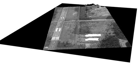
A 3D point cloud of the runway at Bremerhaven Airport.
Benefits
The LidarPod is integrated internally within the S360 itself, rather than being wing-mounted, reducing drag and enabling longer flight and survey times. Integration of the LidarPod into the nose cone minimizes noise and vibration traveling from the rear-mounted engine, ensuring the GNSS/INS is not adversely affected. It also enables more accurate positioning.
The S360 is fixed-wing and built for long-distance flights, with four-hour endurance in the standard configuration, along with long-range telemetry, an autopilot system and a mission planning tool. It works in up to Force 7 winds, extending the operational window in which surveys can be performed. Its significant payload capacity enables the integration of additional survey and geophysical sensors as well as the LidarPod. Because this is an internally integrated solution, it can be set up rapidly and is easy to deploy in the field, Routescene said.
Michael Schmidt, managing director of Hanseatic Aviation Solutions, and Gert Riemersma, CEO of Routescene, met for the first time at INTERGEO 2014. They immediately understood the potential power of a collaboration.
Routescene launched the LidarPod at that trade show. It quickly attracted wide interest and is now generating business across four continents, Routescene said.
After exploratory discussions with clients, the companies started development of the system in earnest at the start of 2015. “We have already seen significant interest from the forestry and geophysical exploration community,” Riemersma said.
Four point clouds, nonregistered, of georeferenced images from four UAV flights.
By Christian Eling, Lasse Klingbeil, Markus Wieland, Erik Heinz and Heiner Kuhlmann
Direct georeferencing with onboard sensors is less time-consuming for data processing than indirect georeferencing using ground control points, and can supply real-time navigation capability to a UAV. This is very useful for surveying, precision farming or infrastructure inspection. An onboard system for position and attitude determination of lightweight UAVs weighs 240 grams and produces position accuracies better than 5 centimeters and attitude accuracies better than 1 degree.
Data acquisition from mobile platforms has become established in many applications recently, particularly using unmanned aerial systems (UASs). Unlike other mobile platforms, unmanned aerial vehicles (UAVs) can overfly inaccessible and also dangerous areas. Furthermore, they can get very close to objects to collect high-resolution data with low-resolution sensors, and they enable approach from all viewing directions without physical contact. UAVs now see use in precision farming for phenotyping or plant monitoring, and in infrastructure inspection and surveying.
Data acquisition from mobile platforms has become established in many applications recently, particularly using unmanned aerial systems (UASs). Unlike other mobile platforms, unmanned aerial vehicles (UAVs) can overfly inaccessible and also dangerous areas. Furthermore, they can get very close to objects to collect high-resolution data with low-resolution sensors, and they enable approach from all viewing directions without physical contact. UAVs now see use in precision farming for phenotyping or plant monitoring, and in infrastructure inspection and surveying.
This article addresses lightweight UAV use for mobile mapping and uses the term micro aerial vehicle (MAV) throughout. MAVs can generally be characterized as having a weight limit of 5 kilograms and a size limit of 1.5 meters.
We focus on the development of a real-time capable, direct georeferencing system for MAVs, since spatial and time restrictions often exclude the possibility of deploying ground control points for an indirect georeferencing. The demand for the real-time capability results from the aim to also use the georeferencing for autonomous navigation of the MAV and to enable a precise time synchronization of the onboard sensors. Furthermore, a real-time direct georeferencing also offers the opportunity to process collected mapping data during flight.
Mapping on demand. The goal of this research project, funded by the Deutsche Forschungsgemeinschaft (DFG), is to develop an MAV that can identify and measure inaccessible three-dimensional objects by use of visual information. A major challenge within this project comes with the term “on demand.” This means that apart from the classical mapping part, where 3D information is extracted from aerial images, the MAV is intended to fly fully autonomously on the basis of a high-level user inquiry. During the flight, obstacles must be detected and avoided. To extract semantic information that can be used to refine the trajectory planning, the mapping data has to be processed in real time. When the georeferencing information is used as initial values for the bundle adjustment, the image processing can be significantly accelerated.
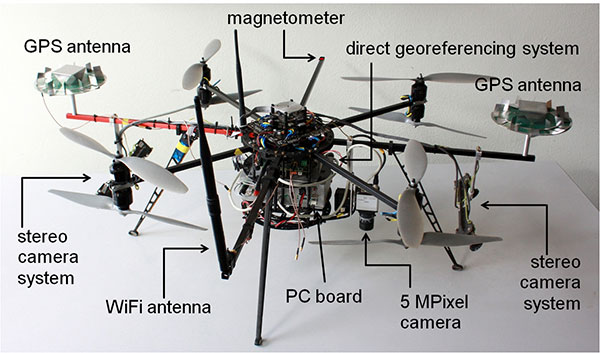
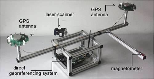
Figure 1 shows the current MAV platform developed in this project. We customized an MAV kit to a coaxial rotor configuration, replaced the centerplates with more stable carbon-fibre plates to stabilize the system, and installed the direct georeferencing and the mapping sensors. The two stereo camera pairs, pointing forward and backward, act as an additional sensory input for the position and attitude determination; the 5M-pixel industrial camera with global shutter is the actual mapping sensor. The PC board is used for onboard image processing, flight planning and machine control; the Wi-Fi module enables a connection to a ground station.
Figure 1. The MAV with mapping and georeferencing sensors, developed for the research project Mapping on Demand.
Although the direct georeferencing system must be small and lightweight, accuracy requirements for its position and attitude determination are high. Generally, these accuracy requirements are different for the machine control, navigation and mapping purposes.
In our project, the MAV is intended to maintain a safety distance of about 0.5 meter to obstacles. Hence, a position accuracy of 0.1 meter is sufficient for the navigation. The absolute attitude accuracy should be in the range of 1 to 5 degrees. For machine control, relative information is more important, and for this the accuracies should be slightly higher.
For mapping purposes, the positions and attitudes have to be known better, since the absolute georeference of the final product (for example, a high-resolution 3D model of a building) is based on the positions and attitudes from the direct georeferencing system. Therefore, the position accuracy should be in the range of 1–3 cm and the attitude accuracy should be better than 1 degree. The relative accuracy of the exterior camera orientation can be improved by a photogrammetric bundle adjustment, but systematic georeferencing errors should be avoided.
To summarize:
The weight of the system has to be less than 500 grams (g), to be applicable on MAVs.
Especially for the control and navigation, the system has to be real-time capable.
All sensors have to be synchronized and outages of single sensors should be bridgeable by other sensors.
The system is intended to provide accurate positions (σpos < 5 cm) and attitudes (σatt < 1 deg) during flights.
The integration of data from additional sensors, such as cameras, should be possible.
The ability to include additional sensors to the system was, apart from the size and the weight constraint, the main reason for developing a proprietary system instead of using a commercial unit with similar capabilities.
Direct Georefencing
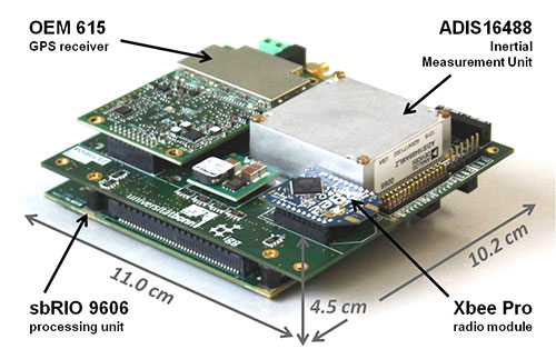
The current version of the system weighs 240 g without GPS antennas (see figure 2). To reduce weight, the antennas were dismantled, reducing their weight from 350 g to 100 g. However, since the antenna reference point got lost in this process, the antennas had to be recalibrated in an anechoic chamber for further use. By comparison to the original antennas, the dismantling led to significant changes in the phase center offsets (circa 4 cm in the Up, < 1 mm in the North and East component) and in the phase center variations (< 5 mm) of the antennas.
Figure 2. The direct georeferencing system.
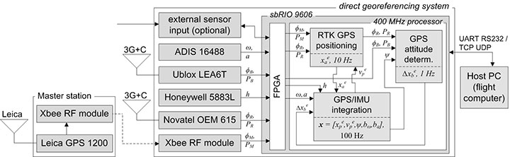
Figure 3 shows a flow chart of the direct georeferencing system with the sensors and the main calculation steps. The system consists of a dual-frequency GPS receiver, a single-frequency GPS receiver, an inertial measurement unit (IMU) and a magnetometer. The dual-frequency receiver is the main positioning device. Together with the GPS raw data from the master station (carrier phases ϕM, pseudoranges PM), which is transmitted via a radio module, the data of the dual-frequency receiver (ϕR, PR) is used for an RTK positioning, leading to centimeter position accuracies.
Figure 3. Flowchart of the direct georeferencing system.
In collaboration with the data of the single-frequency receiver (ϕB, PB), the data of the dual-frequency receiver is also used for GPS attitude determination. The corresponding GPS antennas of these two receivers form a short baseline (baseline length = 92 cm) on the MAV. The determination of the baseline vector in an e-frame (Earth-fixed) enables yaw and the pitch-angle determination.
The tactical-grade micro-electro-mechanical (MEMS) IMU, which includes three-axes gyroscopes, accelerometers and magnetometers, provides angular rates (ω), accelerations (a) and magnetic field observations (h) with high rates (100 Hz) for position and attitude determination. To be unaffected by the electric currents as much as possible, an additional magnetometer is placed on the outer end of one of the rotor-free MAV arms.
The direct georeferencing system further consists of a processing unit, which is a reconfigurable IO board, including a field programmable gate array (FPGA) and a 400-MHz processor. In this combination, the FPGA is used for fast parallel communication with the sensors. Afterwards, the preprocessed sensor data are provided to the 400-MHz processor via direct memory accesses, avoiding delays and supporting the system’s real-time capabilities. Finally, the actual position and attitude determination is carried out on the 400-MHz processor.
Methodologies
All position and attitude determination algorithms running on the system were developed in-house. Generally, the integration of these steps could be realized in one tightly coupled approach. Nevertheless, in the current implementation, we decided to separate the different raw data calculation steps, and we only use interactions at the level of parameters. This approach has the advantage that the integration is more reliable and more practical in the real-time programming.
GPS/IMU integration. In this calculation step, all available sensory input is fused to determine the best position and attitude of the system that is currently available. The GPS and the IMU measurements complement each other well, since the IMU provides short-term stable high-rate (100 Hz) data, and the GPS provides long-term stable low-rate (10 Hz) data.
The GPS/IMU integration can be separated into the strapdown algorithm (SDA) and the Kalman filter update. In the SDA, the high-dynamic movement of the system is determined integrating the angular rates and the accelerations of the MEMS IMU in real time. Because the SDA drifts over time, the long-term stable measurements of the magnetometer and the GPS receivers are needed to correct and bound the drift of the inertial sensor integration, which is realized in an error state Kalman filter.
In the GPS/IMU integration algorithms, the navigation equations of the body frame (b-frame) are expressed in an e-frame. Therefore, the full state vector x includes the position xep and the velocity vep, represented in the e-frame. For the attitude representation a quaternion q is used. Finally, the accelerometer bias bba and the gyro bias bbω are also estimated:
The observations in the measurement model are:
the RTK GPS position xea of the dual-frequency RTK GPS antenna reference point, expressed in the e-frame,
the GPS attitude baseline vector Δxeb, expressed in the e-frame,
the magnetic field vector hb, expressed in the b-frame.
Because the reference point of the RTK GPS antenna is not identical to the system reference point, a lever arm between the system and the antenna reference point must be regarded in the measurement model of the RTK GPS positions. From calibration measurements, the coordinates of the lever arm are precisely known in the b-frame.
In the SDA, a coupling between the accelerations, measured by the IMU, and the positions, measured by the RTK GPS, exists. Due to this coupling the yaw angle can be observed, but only in the presence of horizontal accelerations.
To determine an accurate and reliable yaw angle for every motion behavior, the short GPS baseline is realized on the MAV. A significant challenge in processing this baseline is the ambiguity resolution, because only single-frequency GPS observations can be used. Empirical tests have shown that the ambiguity resolution of a single-frequency GPS baseline generally takes several minutes. Among other strategies, we use the additional information from a magnetometer to improve the ambiguity resolution and to actually enable an instantaneous ambiguity fixing during kinematic applications.
Ferromagnetic material on the UAV and high electric currents of the rotors create significant disturbances of the magnetometer during flight. While the influence of the material can be compensated by calibration procedures, the influence of the dynamically changing electric currents are more challenging. To minimize them, the magnetometer is placed at the outer end of a rotor-free arm of the MAV. Also, the measurement model is arranged so that magnetic field observations only have an impact on the yaw determination in our algorithms.
RTK GPS Positioning. RTK GPS positions are calculated in real time with a rate of 10 Hz. These RTK algorithms are in-house developed, although commercial and open-source solutions are available. The main reasons for developing custom software are the following:
Integration of other sensors and/or solutions is possible, to improve ambiguity resolution and cycle-slip detection.
In commercial software, there is generally no access to the source code.
In the development of a real-time capable system, the software must meet the requirements of the operating system running on the real-time processing unit.
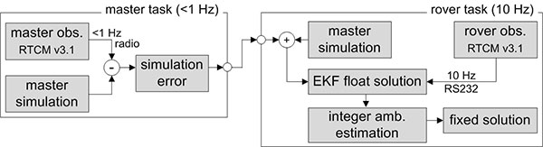
Generally, the RTK GPS algorithm complies with a single baseline determination (one master, one rover), where the master station remains ground-stationary and the rover is onboard the MAV.
To resolve the ambiguities and finally to determine the RTK GPS positions, the parameter estimation is performed in three steps: float solution, integer ambiguity estimation and fixed solution.
The float solution is realized in an extended Kalman filter (EKF). Beside the rover position, represented in the e-frame, the EKF state vector xSD also contains single-difference (SD) ambiguities N j on the GPS L1 and the GPS L2 frequencies. The reason for estimating SD instead of double-difference (DD) ambiguities is to avoid the hand-over problem that would arise for DD ambiguities, when the reference satellite changes.
To allow for an instantaneous ambiguity resolution, the observation vector l consists of DD carrier phases Φjkrm and DD pseudoranges Pjkrm on the GPS L1 and the GPS L2 frequencies.
In the current implementation, a random walk model is assumed as a dynamic model of the MAV in the EKF. Even if this is a simple model, it complies with the movement of the vehicle, when the process noise is chosen appropriately.
The float solution procedure provides real-valued ambiguities and their covariance matrix. These ambiguities now must be fixed to correct integer values, to fully exploit the high accuracy of the carrier phase observables. We applied the MLAMBDA method for integer ambiguity estimation.
Finally, a decision must be made whether or not the result of the integer ambiguity estimation can be accepted. This is done by the simple ratio test. With the ambiguities fixed, the final rover position xae is estimated with cm accuracies.
Usually, the time to fix the ambiguities with the algorithm takes a few epochs, but often the ambiguities can be fixed instantaneously. Once ambiguity resolution has been successful, the ambiguities can be held fixed, as long as no cycle slip or loss of lock of GPS signals occur.
Due to the GPS/IMU integration, we have a precise prediction of the RTK GPS positions between two epochs. Thus, the integration of the inertial sensor readings enables us to detect and also repair cycle slips very reliably.
The observations of the master receiver must be transmitted via radio to the direct georeferencing system. In practice, this data transmission can only be realized with a rate of 1 Hz. To be less dependent on this potentially unreliable master data transmission and the lower sampling rate, simulated master observations are used for RTK GPS position determination. Hence, in the actual processing, the true master observations are only used to update the simulation errors in the master task (figure 4), which have to be applied to correct the simulation results in the rover task.
Figure 4. Task scheduling of the RTK GPS algorithms.
GPS attitude determination. The GPS baseline is determined at 1 Hz. In contrast to the RTK GPS positioning, both antennas of the attitude baseline are mounted on the MAV, so that the complete baseline is moving. Furthermore, the baseline length is constant and known from calibration measurements. The GPS attitude determination also consists of the three steps: float solution, integer ambiguity estimation and fixed solution.
The float solution is also based on an EKF where the single-frequency SD ambiguities N j of the attitude baseline are estimated. Further parameters in the state vector are the baseline parameters and the first deviation of the baseline parameters.
As observations DD carrier phases ΦjkAB and DD pseudoranges PjkAB on the GPS L1 frequency are used. To improve the ambiguity resolution, the attitude from the GPS/IMU integration is added to the observation vector, by transforming the known b-frame baseline parameters into the e-frame. Finally, also the known baseline length can be added as a constraint to the observation vector.
In the integer ambiguity estimation, we apply the MLAMBDA method again. Due to the prior information about the attitude of the baseline, the float ambiguities can already be estimated with high accuracies in the float solution. If the ambiguities could not be fixed with the MLAMBDA method, we consider the 10 best solutions for further processing. Unreliable ambiguity parameters are eliminated in a random order, and the MLAMBDA method is applied again. Afterwards we use the ambiguity function method and the known baseline length to exclude false candidates of the 10 best solutions.
If only one solution remains, the ambiguities can be fixed to integer values. Tests have shown that this approach leads to an instantaneous ambiguity resolution success rate of about 95 percent.
Similar to the RTK GPS positioning, the IMU readings are also used to detect cycle slips for the attitude baseline determination, when the ambiguities have been fixed successfully. With ambiguities fixed, the baseline parameters can be determined with millimeter to centimeter accuracies. This leads to yaw angle accuracies in the range of 0.2–0.5 degrees, when the attitude baseline has a length of 92 cm.
Applications and Results
As mentioned, one goal of Mapping on Demand is 3D reconstruction from visual information. The opening image shows such results. During four flights. images were collected with a sampling rate of 1 Hz, and the position and the attitude of the camera was determined in real time using the direct georeferencing system. A bundle adjustment was processed using these positions and attitudes as initial values. Afterwards, dense point clouds could be generated from the oriented images using an open-source software package (PMVS). Due to georeferencing of the collected images, the point clouds are also georeferenced. The image shows results of four flights in one scene, to demonstrate consistency of the georeferencing.
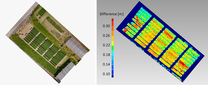
Agriculture. In figure 5, georeferenced images were taken during a flight over a wheat field. The same process was repeated after two weeks. The difference of the respective point clouds, which were determined using the software Photoscan by the company Agisoft, reveals the plant growth at an interval of two weeks. These results show that the determination of plant growth rates, which usually result from time-consuming field work, can be done easily and with high resolution using MAVs. With the use of a direct georeferencing system, this process becomes even more efficient because the deployment of ground control points can be omitted.
Figure 5. Orthophoto of a wheat field (left) and the difference of the vegetation height, determined from the results of two MAV flights at an interval of two weeks (right).
Portable laser scanning system. The small and lightweight design of the direct georeferencing system offers several other opportunities for various applications. One example is the use of the direct georeferencing system in combination with a small, lightweight and low-cost laser scanner.
Terrestrial laser scanning has become an established technology for 3D data acquisition in surveying and mapping because laser scanners provide high-resolution data with high accuracies at high speed. However, for measurement of a complex scene, the laser scanner generally has to be moved to different viewpoints, and all measured scenes have to be registered and georeferenced, a significant increased effort. In contrast, with a directly georeferenced kinematic laser scanning system, complex scenes can be measured with little effort.
Figure 6 shows a portable laser scanning system we developed for kinematic laser scanning. It combines the direct georeferencing system with a low-cost, lightweight 2D time-of-flight laser scanner. Time synchronization and the point cloud calculation are directly realized on this unit.
Figure 6. A directly georeferenced portable laser scanning system for kinematic 3D mapping.
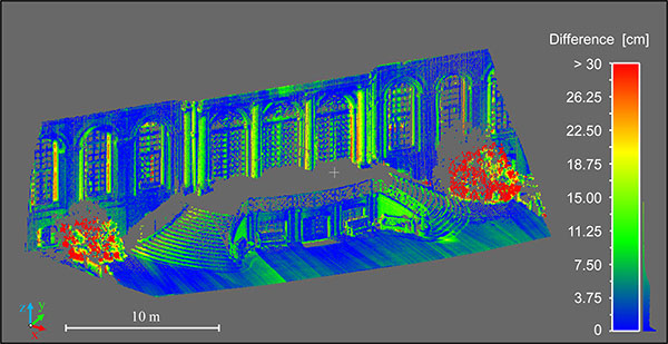
Figure 7 shows differences between a directly georeferenced point cloud, measured by the portable laser scanning system, and a terrestrial laser scanning point cloud, which was indirectly georeferenced using ground control points. Although there are some systematic errors visible, the differences are mostly less than 7.5 cm. The larger differences in the foreground (red) are a result of growing vegetation in the period between both scans. The systematic errors result from the system calibration between the laser scanner and the direct georeferencing system. We are working to improve these calibration methods.
Figure 7. Difference between the results of the directly georeferenced portable laser scanning system and the results of a terrestrial laser scan, which act as reference solution here.
Manufacturers
The MAV is based on a MikroKopter OktoXL assembly kit of HiSystems GmbH. It uses NavXperience 3G+C GPS antennas. The system consists of a dual-frequency NovAtel OEM 615 GPS receiver, a single-frequency u-blox LEA6T receiver, an Analog Devices ADIS 16488 IMU, a Honeywell HMC5883L magnetometer, an XBee Pro 868 radio module, a National Instruments sbRIO 9606 processing unit and a Hokuyo UTM30LXEW 2D time-of-flight laser scanner.
Christian Eling holds an MSc degree in geodesy and is a scientific assistant at the Institute of Geodesy and Geoinformation (IGG) of the University of Bonn.
Lasse Klingbeil received his Ph.D. in experimental physics in 2006. He heads the GNSS and mobile multi-sensor systems group in the IGG. Markus Wieland is a graduade mechanical engineer responsible for the mechanical and electrical design and for the control and readout of various sensor systems at the IGG.
Erik Heinz received his MSc in geodesy and geoinformation from the University of Bonn. He is a Ph.D. student at the IGG. Heiner Kuhlman is a full professor at the IGG. He has worked extensively in engineering surveying, measurement techniques and calibration of geodetic instruments.
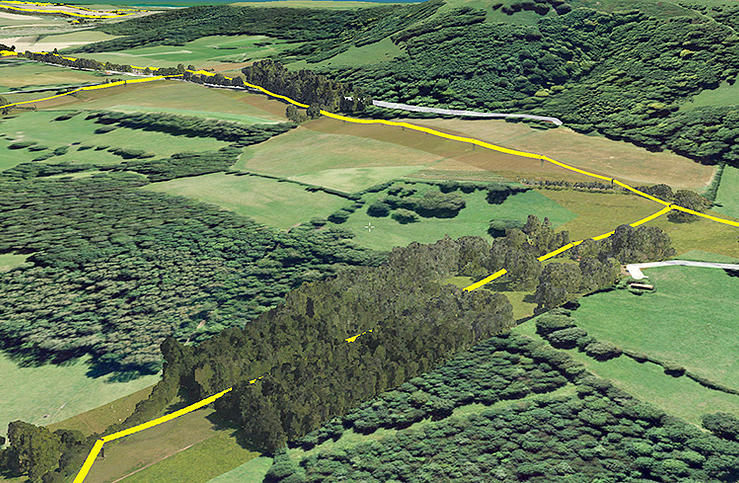
Bluesky has completed a multi-million pound aerial mapping project to assess the impact of vegetation on the electricity network of East Anglia and the South East of England. Working on behalf of UK Power Networks, Bluesky undertook the largest ever combined laser mapping and aerial photography survey commissioned by an electricity distribution network operator in the UK — some 34,000 square kilometers.
The laser mapped (LiDAR) data and aerial photographs were then analyzed to assess the proximity of vegetation to the overhead power lines in order to create a proactive three-year vegetation management program. Bluesky worked in partnership with ADAS, an agricultural and environmental consultancy, to complete the project.
Dedicated survey planes equipped with a lidar mapping system and aerial survey equipment flew the whole of the South East and East of England. Capturing millions of individual laser mapped height measurements and approximately 310,000 aerial images in just over three months, Bluesky successfully completed the unprecedented data capture element of the project within tight project deadlines, in challenging weather conditions and in adherence with strict Air Traffic Control restrictions.
The 80 terabytes of raw data was then processed and analyzed to identify which overhead line spans had vegetation infringement; for example the length of vegetation infestation along each span and its location and distance from the overhead line.
This information has now been incorporated into a 3D web portal that can be viewed from the desktop, enabling UK Power Networks employees to carry out virtual patrols of the network, saving time and reducing the risk of foot patrols, sometimes across difficult terrain including physical barriers such as rivers, ditches, livestock and numerous other potential hazards.
“This innovative £2.5 million project is of immense benefit to our customers and to the company,” said Nigel Hall, head of service development at UK Power Networks. “The risk-based tree-cutting program will help reduce tree-related power cuts for customers, with the additional benefit that it could be carried out without any disturbance to local landowners because it was done from the air rather than on foot.
“As a company it will help us get best value from our £19 million annual tree cutting budget, and the web portal will mean staff can carry out ‘virtual patrols’ from their desk, saving them time and reducing the potential hazards if they had had to walk the lines themselves.”
“Prior to commissioning the LiDAR and aerial mapping project, UK Power Networks undertook regular manual surveys as part of its assessment of network resilience, but the capture of LiDAR and associated aerial photography for the entire catchment area allows for evidence based decision making and long term planning, and provides a proven solution for other network operators,” added Rachel Tidmarsh, managing director of Bluesky.
Roy Dyer, Head of Arboriculture in ADAS and manager of the ADAS contribution to this contract said, “This has been a ground breaking contract. The combination of Bluesky’s technical ability and ADAS’ consultancy experience in managing vegetation near overhead lines enabled us to successfully deliver this challenging contract and improve the management and resilience of the overhead lines owned by UK Power Networks.”


 By Tracy Cozzens, Managing Editor