By Airman 1st Class Jonathan Whitely, 50th Space Wing Public Affairs
News from Schriever Air Force Base
The 2nd Space Operations Squadron performed the first station keeping maneuver on a GPS III satellite to Satellite Vehicle Number 75 on May 14 at the Schriever Air Force Base in Colorado.
The maneuver set a new standard for how GPS maneuvers should be conducted for the squadron that provides precision, navigation and timing signals to billions of users around the world.
A station keeping maneuver is performed to keep vehicles in their node (or parking spots in orbit) and involves burning the satellite’s thrusters and changing the vehicles speed at a particular point in its orbit. This causes the orbit to change, in turn, keeping the vehicle in the ideal position to provide coverage.
“All operational GPS vehicles are assigned nodes, when all nodes are filled with healthy vehicles there is good global GPS coverage,” said 1st Lt. Michael Gallagher, GPS subsystems analyst. “When new vehicles are launched they typically aren’t launched directly into their final node. This means that the 2 SOPS analysis flight must perform a re-phase maneuver to put a vehicle in its node.”
The maneuver required GPS III’s signal to be turned off. Turning off the navigation signal while performing the maneuver prevents users from receiving inaccuracies generated by a change in satellite velocity.
“This was a new process that we could learn from as it was the first station keeping [maneuver] performed for the newest generation of GPS satellites,” said Senior Airman Harrison Sherwood, 2 SOPS satellite systems operator, who sent the commands to the satellite during the maneuver. “[Since] this was the first [maneuver] of the newest generation satellites, it was a bit of a guinea pig for future maneuvers.”
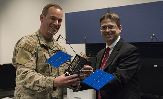
Johnathon Caldwell, Lockheed Martin Space vice president of navigation systems, right, presents Lt. Col. Stephen Toth, 2nd Space Operations Squadron commander, with a GPS III model satellite as a token of appreciation for the 2nd SOPS critical mission in space at Schriever Air Force Base, Colorado, July 29, 2019. The squadron performed its first station keeping maneuver on a GPS III satellite May 14, 2020, at Schriever AFB. (Photo: U.S. Air Force/1st Class Jonathan Whitely)
However, the unit was able to complete the maneuver flawlessly. The maneuver was completed in a special mission area and there were no changes to the normal operations floor.
“This maneuver had no effect on the rest of the [GPS satellite] constellation,” Gallagher said. “SVN-45 was in the node SVN-75 was being placed into, so there was no decrease in GPS signal quality as a result of this maneuver.”
This procedure was also the first of its kind to be performed with the 2nd SOPS Architecture Evolution Plan, which all active satellites in the program are operated. Since GPS III vehicles are fully integrated into the program with this maneuver, all maintenance is conducted through AEP.
“Station keeping maneuvers are essential to satellite operations and must be done for regular maintenance,” said 2nd Lt. Tyler Gorman, 2nd SOPS navigation payload engineer. “This activity helped validate a nominal maintenance activity for a new generation of vehicles.”
The unit plans to continue to use this new method and program for future GPS satellites that are being launched and need to be re-phased into their operation slots. The next satellite that will need a station maneuver performed is SVN-76, which is scheduled to launch in the next few months.
“GPS maintenance requires a coordinated effort to ensure our worldwide service is preserved,” Gorman said. “That means careful planning and execution from our analysts in 2 SOPS, our satellite system operator and the operational support from Lockheed Martin and the Aerospace Corporation.”
By Peter Steigenberger, Steffen Thoelert, Oliver Montenbruck and Richard B. Langley
The first GPS III satellite, “Vespucci,” was launched in December 2018, started signal transmission in January 2020, and was set healthy later that month. The second GPS III satellite, nicknamed “Magellan,” was launched on Aug. 22, 2019, on a Delta IV rocket from Cape Canaveral, Florida.
Magellan, also identified by its space vehicle number (SVN) 75 (here referred to as GPS-75), started signal transmission with standard pseudorandom noise code (PRN) number 18 (here referred to as G18) on March 13. The L1 C/A, L1 P(Y), and L2 P(Y) signals were activated at 17:16:30 GPS Time (GPST), while the L1C, L2C and L5 signals followed less than two hours after Vespucci’s launch at 18:59:30 GPST. Transmission of navigation messages started at 19:00:00 GPST with GPS-75 (G18) marked as unhealthy.
PRN G18 was previously used by the 27-year-old Block IIA satellite GPS-34 that had been already removed from the active GPS constellation on Oct. 7, 2019, but continued signal transmission until March 9, 2020. GPS-75 is already being tracked by a large number of tracking stations of the International GNSS Service (IGS). Based on the data collected by these stations, the Center for Orbit Determination in Europe (CODE), headquartered in Bern, Switzerland, has been providing precise orbit and clock products for this satellite since March 14.
A comparison we performed with the CODE precise orbit products revealed initial broadcast ephemeris errors of up to 100 meters (3D) and an orbit-related signal-in-space range error (SISRE) of about 13 meters. Within four days, a SISRE (orbit component) of 24 centimeters was achieved, which closely matches the performance of the rest of the GPS constellation.
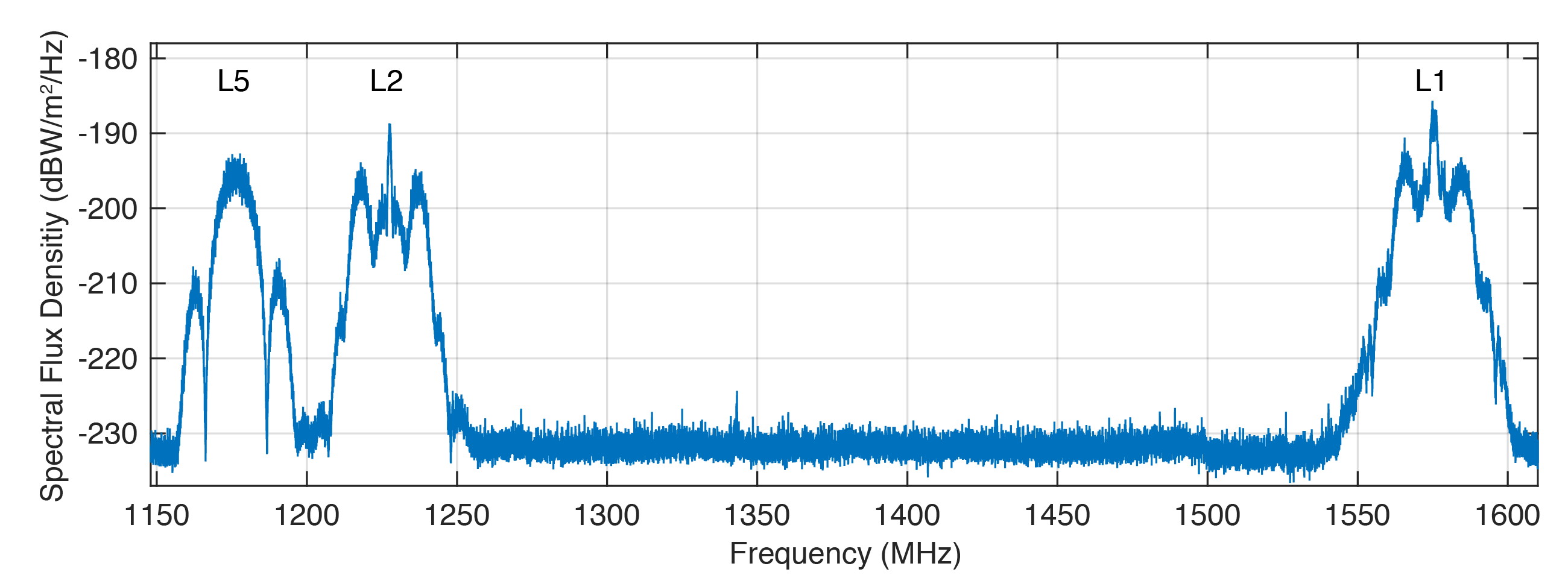
Figure 1 shows the spectral flux density of GPS-75 in the L1, L2 and L5 frequency bands obtained with the 30-meter high-gain antenna of the German Aerospace Center (DLR) located in Weilheim, Germany. The civil L1 C/A, L1C and L2C signals can be identified as sharp peaks in the center of the respective frequency bands.
FIGURE 1. Spectral flux density of GPS-75 measured with DLR’s 30-meter high-gain antenna. (Figure: Steigenberger, et al)
The prominent side lobes in the L1 and L2 bands are associated with the military M-code. The wide main lobe of the L5 signal with two smaller and sharper side lobes is caused by the superposition of two in-phase and quadrature signals with a 10-MHz binary phase-shift keying (BPSK) modulation. We found that all signals are in good shape and have a quality similar to that of the first GPS III satellite.
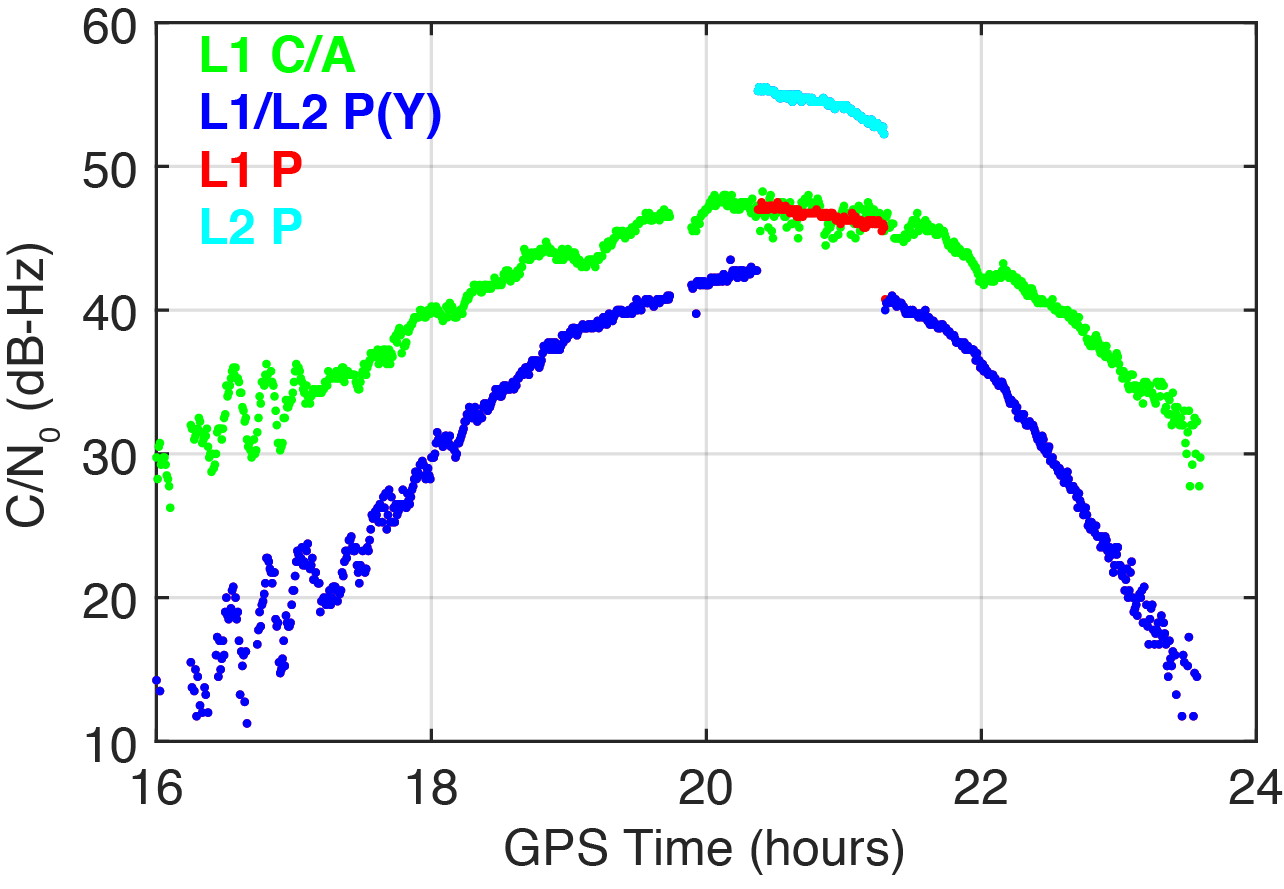
On March 16, 2020, we detected a significant change in the carrier-to-noise-density ratio of the L1 and L2 P(Y)-code signals. Figure 2 illustrates these changes for the IGS station located in Patumwan, Thailand (CUSV00THA). The L1 and L2 P-code signals are usually encrypted with the W-code to prevent spoofing (the generation of fake signals by adverse parties). The resulting encrypted signals are denoted by P(Y). Geodetic GNSS receivers are capable of tracking the P(Y) signals with a semi-codeless approach.
FIGURE 2. Carrier-to-noise-density ratio (C/N0) of the second GPS III satellite, GPS-75, tracked by the IGS station CUSV00THA in Patumwan, Thailand, on March 16, 2020. Between 20:22 and 21:18 GPST, unencrypted P-code signals were tracked. (Figure: Steigenberger, et al)
As a result, C/N0 of L1 P(Y) and L2 P(Y) are virtually identical and significantly smaller than the C/N0 of the unencrypted signals due to losses of the semi-codeless tracking technique. This can be seen in the blue-colored plot of Figure 2, where the C/N0 values of L1 P(Y) and L2 P(Y) are identical and smaller by 4.5–16 dB compared to L1 C/A depending on the elevation angle of the satellite.
However, between 20:22 and 21:18 GPST, an increase of the P-code C/N0 values was observed. The values changed by 4.5 and 12.5 dB for L1 and L2, respectively. This change is an indicator that unencrypted P-code signals were transmitted, rather than encrypted ones. This assumption can be verified by the “Anti-Spoof Flag” given as the 19th bit of the handover word (HOW) of the GPS LNAV navigation message.
Indeed, decoding of the raw navigation data from the IGS station CHOF00JPN in Chofu, Japan, showed that the Anti-Spoof Flag indicated a deactivation of anti-spoofing between 20:22:00 and 21:17:48 GPST and verified our assumption that unencrypted P-code signals were transmitted during that time period.
It has to be noted that only Javad receivers within the global multi-GNSS network of the IGS show this increase in C/N0. Other receiver types report continuous C/N0 values for the P-code signals, indicating that a semi-codeless tracking technique was continuously applied irrespective of the Anti-Spoof Flag.
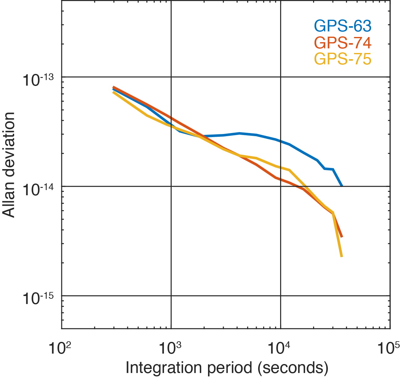
Figure 3 shows the two GPS III satellites’ Allan deviation, which measures the clock stability achieved in orbit; that is, the average frequency error over different time scales. In addition, the Block IIF satellite GPS-63 is shown, which is in the same orbital plane as GPS-75.
FIGURE 3. Allan deviation of the Block IIF satellite GPS-63 and the GPS III satellites GPS-74 and GPS-75 computed from 5-minute clock solutions produced by DLR. (Figure: Steigenberger, et al)
For integration times up to 2,000 seconds, the clock stability of GPS-75 is slightly better compared to the first GPS III satellite, GPS-74, but the situation is opposite for integration times larger than 5,000 seconds. The latter finding might be caused by the fact that GPS-75, unhealthy at the time, was tracked by a smaller number of stations compared to the healthy GPS-74.
As a consequence, the observed Allan deviation may partly be contaminated by orbit determination errors. In any case, both GPS III satellites clearly outperform the Block IIF satellite GPS-63 that suffers from thermal line bias variations visible as an increased Allan deviation starting at an integration time of about 2,000 seconds.
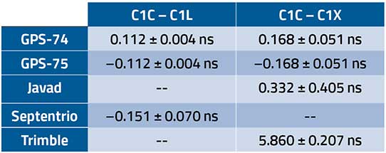
The activation of the second GPS III satellite transmitting the new civil L1C signal enables the estimation of differential code biases (DCBs) between, for example, the L1 C/A signal (Receiver Independent Exchange [RINEX] format observation code C1C) and different tracking modes of the L1C signal. Septentrio receivers track only the pilot component of the L1C signal (C1L), whereas Javad and Trimble receivers perform a combined data+pilot tracking (C1X).
DCBs are estimated from pseudorange (code) observations of a global tracking network and are corrected for ionospheric delays obtained from global ionosphere maps. The DCB estimates shown in Table 1 are based on eight days of data from 10 Javad, 21 Septentrio and 3 Trimble receivers.
TABLE 1. Differential code bias estimates in nanoseconds between L1 C/A and L1C for the GPS III satellites and average receiver DCBs. (Data: Steigenberger, et al)
As we have applied a zero-sum condition for the estimation of satellite DCBs of just two satellites, the values of GPS-74 and GPS-75 obtained from the same type of L1C observables differ only by the sign. The DCBs estimated from different L1C observables, namely C1L and C1X, differ by 56 picoseconds, corresponding to a range difference of 1.7 centimeters. The receiver DCBs are quite homogeneous for receivers from each manufacturer but differ by up to 6 nanoseconds between various manufacturers.
On April 1, 2020, GPS-75 was set healthy and joined the constellation of operational GPS satellites. The third GPS III satellite, named “Columbus,” was shipped to the Cape Canaveral launch site in February 2020. Its launch is expected no earlier than June 30, 2020, and at least two GPS III launches per year are planned for the near future.
Equipment. Measurements reported in this article were collected with JAVAD GNSS TRE_G3TH and TRE_3, Septentrio PolaRx5 and Trimble Alloy multi-GNSS, multi-frequency receivers. The spectral overview was captured with a Rohde & Schwarz EM100 digital compact receiver.
PETER STEIGENBERGER and OLIVER MONTENBRUCK are scientists at the German Space Operations Center of the German Aerospace Center (DLR). STEFFEN THOELERT is an electrical engineer at DLR’s Institute of Communications and Navigation. RICHARD B. LANGLEY is a professor at the University of New Brunswick and editor of the “Innovation” column for GPS World magazine.
Further Reading
“Optimum Semicodeless Carrier-Phase Tracking of L2” by K.T. Woo in Navigation, Vol. 47, No. 2, 2000, pp. 82-99, doi: 10.1002/j.2161-4296.2000.tb00204.x.
Interface Specification IS-GPS-200K: NAVSTAR GPS Space Segment/User Segment Interfaces by Global Positioning Systems Directorate Systems Engineering & Integration, Los Angeles Air Force Base, El Segundo, California, March 4, 2019. Available online: https://www.gps.gov/technical/icwg/IS-GPS-200K.pdf
“Apparent Clock Variations of the Block IIF-1 (SVN62) GPS Satellite“ by O. Montenbruck, U. Hugentobler, E. Dach, P. Steigenberger and A. Hauschild in GPS Solutions, Vol. 16, No.3, 2012, pp. 303-313, doi: 10.1007/s10291-011-0232-x.
“Differential Code Bias Estimation Using Multi-GNSS Observations and Global Ionosphere Maps” by O. Montenbruck, A. Hauschild and P. Steigenberger in Navigation, 2014, Vol. 61, No. 3, 2014, pp. 191-201, doi: 10.1002/navi.64
The U.S. Coast Guard has issued a Notice Advisory to Navstar Users (NANU) detailing the changes to the constellation now that the second GPS III satellite has joined.
The U.S. Space Force Second Space Operations Squadron (2 SOPS) issued an Initial Use (USABINIT) NANU for the second of the new generation of GPS-III satellites, designated SVN-75/PRN-18.
SVN-75 was launched on Aug. 22, 2019, and — having successfully undergone rigorous operational testing on orbit — has taken its place in the active GPS constellation with the slot and plane designation of D6.
Constellation changes
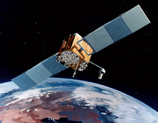
Artist’s rendering of GPS IIF satellite. (Image: U.S. Air Force )
SVN-45/PRN-21 is being re-phased from D3 to D2F replacing SVN46. Upon its arrival, SVN-46/PRN-11 will then be moved to residual status in Launch, Anomaly and Disposal Operations (LADO).
SVN-60/PRN-23 was decommissioned on March 2, eight and a half years beyond its expected service life. SVN-60 was the 12th GPS-IIR to go in to orbit, and began service on July 9, 2004.