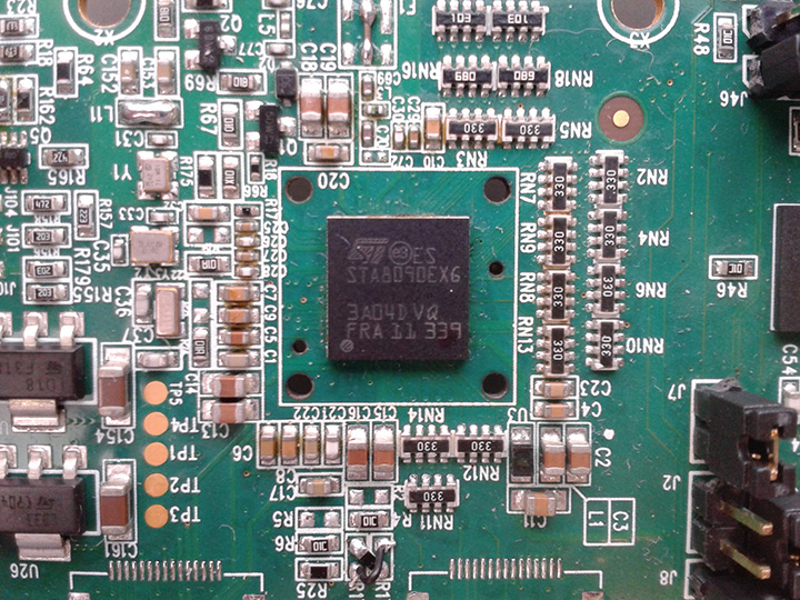
STMicroelectronics has grown its GNSS product offering with the Teseo-LIV3R ROM-based module. The module provides ST’s full GNSS algorithm capability for cost-conscious tracking and navigation devices.
ST’s new GNSS module provides odometer functionality with three trip counters and reached-distance alert, along with geofencing capabilities with up to eight configurable circles and crossing-circles alarm. Support for real-time assisted GNSS with free server access ensures uninterrupted positioning data for dependable navigation.
Simultaneous tracking of GPS, GLONASS, BeiDou and QZSS constellations, with satellite-based augmentation system (S-BAS) and Radio Technical Commission for Maritime Services (RTCM) V3.1 differential positioning ensures excellent accuracy to within 1.5 meters (50% circular error probability, CEP).
Tracking sensitivity of -163 dBm and time-to-first-fix faster than one second ensure high performance for demanding applications. The module is easy to use and responds to proprietary National Marine Electronics Association (NMEA) commands.
With scalable power consumption according to accuracy, average current, and frequency of fixes, a sub-15µA standby mode with RTC backup, and support for multiple low-power modes, Teseo-LIV3R is an ideal choice for battery-sensitive applications. The low-power modes include continuous-fix with adaptive and power-saving cycled modes, periodic-fix with GPS only, and fix-on-demand with the device in permanent standby.
To simplify and accelerate new-product development, the module is FCC certified and is supported by the STM32 Open Development Environment. STM32 applications for advanced geolocation, smart tracking, and server-assisted GNSS are available, while the EVB-LIV3x evaluation board and X-NUCLEO-GNSS1A1 expansion board provide a head-start with hardware. The Teseo Suite PC tool helps easily configure settings and fine-tune performance. Developers can also join the ST GNSS community to share information and increase their understanding of the field.
The Teseo-LIV3R is in volume production. The 9.7mm x 10.1mm LCC18 module is priced from $7.3 for orders of 1,000 pieces.
The tools connect directly to TomTom Maps APIs (Application Programming Interfaces) for location, tracking and mapping data services, accelerating product development, and reducing time-to-market and development costs for developers, the companies said.
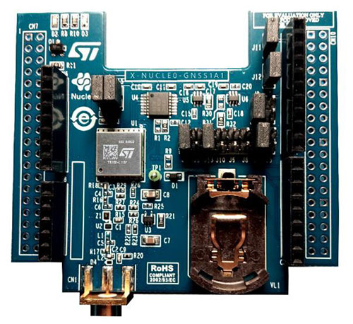
The X-NUCLEO-GNSS1A1 expansion board is based on the Teseo-LIV3F tiny GNSS module. (Photo: STMicroelectronics)
The development package consists of an STM32 Discovery host board for 2G/3G cellular-to-cloud connectivity, a GNSS expansion board based on ST’s Teseo satellite navigation technology, and a software Function Pack that connects an internet-of-things (IoT) node via a cellular network to a range of TomTom Maps APIs.
With this hardware and software package and a TomTom developer account, developers can quickly add location-based services to their IoT and smart city applications.
Among these services are the translation of GPS coordinates into a street address inside a map (Reverse Geocoding), retrieval of nearby point of interests, and the production of accurate navigation directions.
“We have combined TomTom’s industry-leading location-based and mapmaking technologies with ST’s unrivaled combination of silicon and system expertise to create a unique offering that provides easy access to TomTom’s Maps APIs to empower developers to create groundbreaking, location-aware applications faster and more efficiently,” said Anders Truelsen, managing director of TomTom’s Enterprise Business Unit.
“Supporting our efforts to facilitate location-based product development, our collaboration with TomTom has built on each company’s strengths to assemble a tailored package of hardware and software tools that is already fully integrated with TomTom cloud services, around the popular STM32 development ecosystem,” said Alessandro Cremonesi, group vice president at STMicroelectronics. “These tools enable native STM32-based location services to accelerate application development of Geo-IoT solutions for fleet management, item tracking, and many other services that depend on fast, accurate location detection.”
In addition to the STM32 family of Arm Cortex-M core microcontrollers, the development tools leverage ST’s market-proven multi-constellation Teseo positioning-receiver technology to perform all positioning operations including tracking, acquisition, navigation and data output.
NovAtel has demonstrated high-accuracy positioning performance using automotive-grade GNSS chipsets Teseo APP and Teseo V from STMicroelectronics. Combining automotive-grade multi-frequency GNSS chipsets with positioning algorithms and correction services from NovAtel improves the achievable positioning accuracy available to automotive users and provides a solution suitable for autonomous operation.
According to the company, these chipsets provide multi-frequency GNSS data for precise point positioning (PPP) and real-time kinematic (RTK) to enable accurate positioning capabilities. Teseo APP features built-in integrity checking for use in safety-critical systems, whereas Teseo V is used for non-safety-critical precise positioning applications.
The collaboration between the two companies is designed to reach car manufacturers and Tier 1 suppliers for future production models.
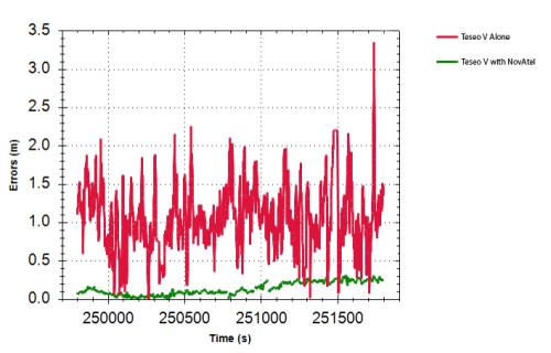
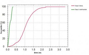
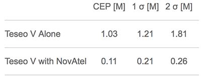
Test results: Horizontal position errors. Teseo V alone is shown in red, Teseo V + NovAtel in green. Test results: Horizontal cumulative error distribution. Teseo V alone is shown in red, Teseo V + NovAtel in green. (Chart: NovAtel)
Test results: Horizontal cumulative error distribution. Teseo V alone is shown in red, Teseo V + NovAtel in green. (Chart: NovAtel)
Driven Today. “STMicro is one of many chipset manufacturers coming to market with dual-frequency chipsets targeting the automotive sector,” said Jonathan Auld, VP Engineering and Safety Critical Systems for NovAtel. “We are taking advantage of their expertise in automotive measurement engines for high-volume, cost-effective reliable positioning. NovAtel brings high-precision algorithm expertise and integration with global corrections supplied by Hexagon Correction Services to this initiative.”
NovAtel’s positioning engine combines the GNSS measurements from these chipsets with inertial measurement unit (IMU) data and Hexagon Correction Services to deliver centimeter-level PPP positioning solutions in real time.
“Working closely with STMicroelectronics allowed us to innovate and drastically reduce time to market of our assured positioning solution tailored specifically for safe positioning of autonomous vehicles,” added Auld.
Comparison of GNSS Performance possible in automotive today (red), L1 automotive with corrections (green) and L1/L2 automotive with corrections (blue).
Driverless Tomorrow. “Precise absolute positioning is just one piece of the overall autonomous vehicle puzzle and must be done with safety and integrity concepts in mind.” Auld pointed to the partnership announced in 2016 between NovAtel, the Illinois Institute of Technology, and Stanford University to conduct leading-edge research to determine how GNSS technology can deliver a positioning solution that meets both the safety and accuracy requirements of autonomous automotive vehicles.
Previous research by academia and industry into GNSS integrity produced the successful WAAS program for aviation. The new work underway will extend the scope to include the autonomous ground vehicle use case. The research includes updated and expanded concepts for high-integrity carrier-phase algorithms as well as expanded threat models and safety monitors.
At the Automotive Tech.AD in Berlin, Auld added: “Today the primary use case for positioning in navigation is single-frequency GNSS, with up to 2 constellations, using narrowband RF and antennas, obtaining accuracy at the 1–2 meter level. This is primarily done with pseudorange-based positioning techniques, with some carrier-phase assistance. There are no functional safety standards, and so safety data is provided on the output solution.”
Autonomous Requirements. By contrast, he continued, autonomous operation will require lane-level and better accuracy: 3D centimeter to decimeter absolute positioning. This means multi-frequency, multi-constellation receivers and antennas to improve overall accuracy and increase available measurements. It will also require increased availability through sensor fusion with IMUs and other sensors. All of this must be brought together through a functionally safe development process targeted at ISO26262 Automotive Safety Integrity Level (ASIL) B.
Moving from meter to centimeter level position requires additional processing to handle all the added signals coming in; residual monitoring and observation exclusion, and carrier phase, “the key to centimeter-level positioning,” as opposed to code phase. The vehicle’s localization system must include enhanced positioning algorithms for multipath mitigation, a fast converging corrections network, enhanced Kalman Filters, and sophisticated sensor fusion.
Flexible Integration. NovAtel’s positioning engine architecture enables a flexible integration with different GNSS receiver chipsets, augmentation sensors and processor environments, providing automotive manufacturers with additional flexibility when it comes to sourcing of components and subsystems of advanced driver assistance systems (ADAS) and autonomous driving solutions.
The positioning engine is being developed to ASIL-B standards and will include a proprietary GNSS integrity solution to ensure safe positioning within defined protection limits tailored to the customer’s application requirements.
NovAtel has integrated its high-precision positioning engine and correction services with automotive-grade multi-frequency GNSS chipsets from STMicroelectronics: specifically, the Teseo APP (Automotive Precise Positioning) and Teseo V.
The integration demonstrates possibilities for vehicle localization solutions. NovAtel is part of Hexagon’s Positioning Intelligence Division.
STMicroelectronics’s Teseo APP and Teseo V provide multi-frequency GNSS data for PPP (precise point positioning) and RTK (real-time kinematic) for accurate positioning capabilities.
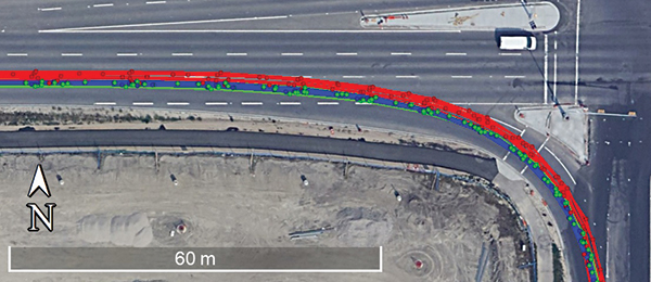
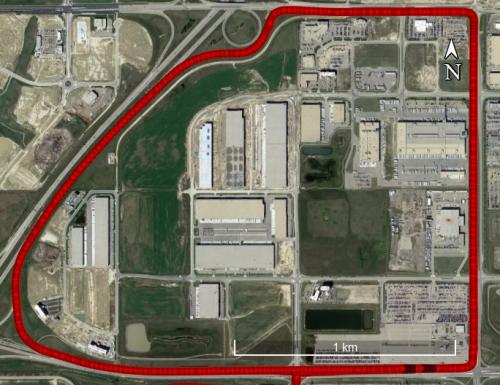
The Teseo V SBAS and Teseo V NovAtel PPP tests took place in a light urban environment. (Image: NovAtel)
NovAtel’s positioning engine combines the GNSS measurements from these chipsets with inertial measurement unit (IMU) data and Hexagon PPP correction services on the demonstration platform to deliver centimeter-level PPP positioning solutions in real time.
“Working closely with STMicroelectronics using their Teseo APP chipset allowed us to innovate and speed up the development of our assured positioning solution tailored specifically for safe positioning of autonomous vehicles,” said Jonathan Auld, VP Engineering and Safety Critical Systems from NovAtel.
NovAtel’s positioning engine architecture enables a flexible integration with different GNSS receiver chipsets, IMUs and processor environments, providing automotive manufacturers with additional flexibility when it comes to selecting components and subsystems of advanced driver assistance systems (ADAS) and autonomous driving solutions.
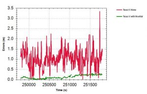
Test results: Horizontal position errors. Teseo V alone is shown in red, Teseo V + NovAtel in green. Test results: Horizontal cumulative error distribution. Teseo V alone is shown in red, Teseo V + NovAtel in green. (Chart: NovAtel)
Test results: Horizontal cumulative error distribution. Teseo V alone is shown in red, Teseo V + NovAtel in green. (Chart: NovAtel)
The positioning engine is being developed to ASIL-B standards according to ISO26262 and will include a proprietary GNSS integrity solution to ensure safe positioning within defined protection limits that are tailored to the customer’s application requirements.
“NovAtel’s choice of the automotive-quality ASIL-capable Teseo APP to integrate with their GNSS positioning engine is enabling them to develop a world-class safety-critical positioning offering to the automotive industry,” said Antonio Radaelli, Director, Infotainment Business Unit, STMicroelectronics.
NovAtel technology continues to be an integral part of the connected and autonomous car ecosystems, including academic research, industry development and real-life applications. The company’s automotive positioning solution includes automotive GNSS antenna technology, GNSS/INS positioning engine, and global correction services.
STMicroelectronics is bringing next-generation satellite navigation to today’s drivers with the launch of enhanced, always-available, always-accurate 3D positioning on its TESEO III automotive-navigation integrated circuits (ICs).
The new TESEO DRAW firmware for ST’s multi-constellation positioning chips enables navigation devices to provide continuous, accurate location and turn-by-turn instructions even when satellite signals are poor or unavailable, such as in tunnels, covered car parks, or multi-level highways. TESEO DRAW also enhances performance in built-up areas, such as in urban canyons, where conventional navigation systems can lose accuracy.
TESEO DRAW merges the satellite information with data from vehicle sensors such as the gyroscope, accelerometer and wheel-speed sensors, to calculate location accurately in three dimensions including elevation. If the satellite signal is poor, TESEO DRAW compensates for the loss of accuracy, and if the signal becomes unavailable, navigation continues uninterrupted based on calculated location (dead reckoning). Road tests carried out by ST in difficult under-cover and urban environments have demonstrated continuous tracking from entry to exit in complex multi-level car parks, and at street level between tall buildings, where conventional systems have been unable to track the vehicle.
By enabling high-accuracy 3D dead reckoning, TESEO DRAW expands the opportunities for developers to commercialize new applications, the company said.
“TESEO DRAW strengthens GNSS performance and eliminates barriers to continuity, enabling exciting new services to emerge,” said Fabio Marchiò, Microcontroller and Infotainment Division general manager, Automotive Product Group, STMicroelectronics. “Users can also experience significant improvements in existing services such as fleet tracking, eCall, or ERA-GLONASS emergency response, usage-based insurance, road tolling, and anti-theft systems.”
TESEO DRAW firmware has multiple modes and is capable of referring to sensors on the vehicle’s CAN bus or discrete sensors such as the odometer, reverse sensor, MEMS accelerometer and gyroscope, or MEMS inertial module connected to the TESEO III IC.
ST is a supplier of MEMS motion sensors for automotive navigation, telematics and vehicle alarm systems, and is a provider of navigation engines with its TESEO IC family. With the launch of TESEO DRAW firmware, ST is able to provide a unified platform comprising navigation engines, 3D positioning capability and motion sensors.
TESEO III ICs loaded with the new TESEO DRAW firmware are sampling now, and will enter mass production in Q1 2016.
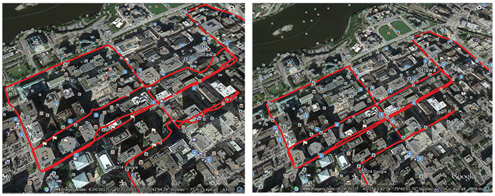
A single-feed smart antenna (left) compared to the multipath rejection results of the new TW5340 smart antenna with Accutenna technology. Photo: Tallysman
Tallysman’s new TW5340 smart antenna is designed to pair Tallysman‘s Accutenna technology antenna with STMicroelectronics’ Teseo II receiver. The combination makes the smart antenna accurate for use in all environments, including urban canyons, according to the company.
The TW5340 is a multi-constellation GNSS Smart Antenna that provides simultaneous GPS/GLONASS/SBAS reception. It is designed for use in professional-grade applications such as precision timing, network synchronization, low current applications, and tracking/positioning applications.
To illustrate the advantages of this technology coupling, simultaneous recordings of vehicle position were conducted using two smart antennas — one with and one without Tallysman’s Accutenna technology — in an area of downtown Ottawa, Canada, notorious for high levels of multipath signals. Results show how the high multipath signal rejection capabilities of Tallysman’s Accutenna technology greatly improves accuracy, the company said.
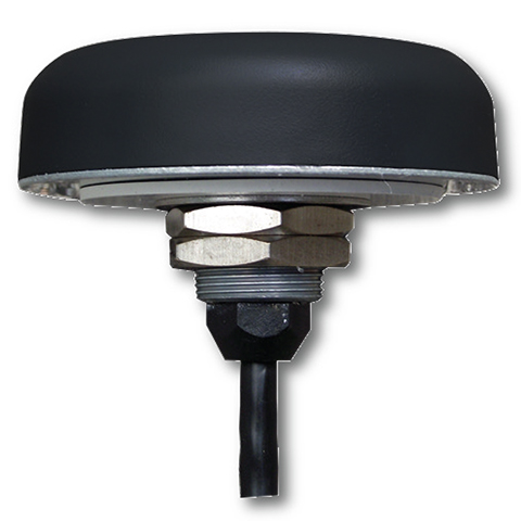
The Tallysman TW5340 smart antenna.
The TW5340 supports STMicroelectronics Autonomous A-GPS, which accelerates GPS positioning by predicting satellite ephemeris data based on previous observations. This results in extremely fast time-to-first-fix. The TW5340 can be configured to output up to three NMEA 0183 message lists with navigation update rates up to 10 Hz. RS232, CMOS, and USB interfaces are available with input voltage options of 3,3V, 5.0V, and 12V. A standby-mode feature provides for very low current consumption (<100uA) and is particularly useful in battery-operated applications.
A standard one pulse-per-second 1PPS synchronized to UTC time is available as a single ended output or as a differential output at RS422 levels.
Tallysman’s Windows-based Configurator enables simple configuration of parameters such a baud rates, output message rates, constellation, tracking parameters, 1 PPS configuration and standby-mode parameters.
The TW5340 is housed in an IP67 housing and is REACH and ROHS compliant. A non-magnetic version is also available as Part Number TW5341.
The implementation changes and first live tests of BeiDou and Galileo on Teseo-3 GNSS chips developed in 2013 are covered, bringing it to a four-constellation machine. By 2020, we expect to have four global constellations all on the same band, giving us more than 100 satellites — under clear sky, as many as 30 or 40 simultaneously.
By Philip G. Mattos and Fabio Pisoni
Multi-constellation GNSS first became widely available in 2010/2011, but only as two constellations, GPS+GLONASS. Although receivers at that time may have supported Galileo, there were no usable satellites. BeiDou was a name only, as without a spec (an interface control document, or ICD), no receivers could be built. However, the hardware development time of receivers had been effectively shortened: the Galileo ICD had been available for years, BeiDou codes had been reverse-engineered by Grace Gao and colleagues at Stanford, and at the end of 2011 they were confirmed by the so-called test ICD, which allowed signal testing without yet releasing message characteristics or content.
The last weeks of 2012 saw two great leaps forward for GNSS. Galileo IOV3 and 4 started transmitting at the beginning of December, bringing the constellation to four and making positioning possible for about two hours a day. At the end of December, the Chinese issued the BeiDou ICD, allowing the final steps of message decode and ephemeris calculation to be added to systems that had been tracking BeiDou for many months, and thus supporting positioning. The Teseo-2 receiver from STMicroelectronics has been available for some years, so apart from software development, it was just waiting for Galileo satellites; however, for BeiDou it needed hardware support in the form of an additional RF front end. Additionally, while it could support all four constellations, it could not support BeiDou and GPS/Galileo at the same time, as without the BeiDou ICD the spreading codes had to be software-generated and used from a memory-based code generator, thus blocking the GPS/Galileo part of the machine.
The Teseo-3 receiver appeared late in 2013, returning to the optimum single-chip form factor: RF integrated with digital silicon and flash memory in the same package, enabling simultaneous use of BeiDou and GPS/Galileo signals. Multi-constellation in 2012 was GPS+GLONASS, which brought huge benefits in urban canyons with up to 20 visible satellites in an open sky. Now, for two hours a day in Europe while the Galileo IOVs are visible, we can run three constellations, and in the China region, GPS/BeiDou/Galileo is the preferred choice.
This article covers the first tracking of four Galileo satellites on December 4, 2012, first positioning with Galileo, and first positioning with BeiDou in January 2013. It will cover static and road tests of each constellation individually and together as a single positioning solution. Road tests in the United States/Europe will combine GPS/GLONASS/Galileo, while tests in the China region will combine GPS/Galileo/BeiDou. Results will be discussed from a technical point of view, while the market future of multi-constellation hardware will also be considered.
In the 2010–2020 timeframe, GLONASS and BeiDou (1602 MHz FDMA and 1561 MHz respectively) cost extra silicon in both RF and digital hardware, and cause marginal extra jamming vulnerability due to the 50 MHz bandwidth of the front end. The extra silicon also causes extra power consumption.
After 2020, GLONASS is expected to have the L1OC signal operational, CDMA on the GPS/Galileo frequency, and BeiDou is expected both to have expanded worldwide, and also to have the B3 signal fully operational, again on 1575 MHz. At that point we will have four global constellations all on the same band, giving us more than 100 satellites. With a clear sky, the user might expect to see more than 30, sometimes 40, satellites simultaneously.
Besides the performance benefits in terms of urban canyon availability and accuracy, this allows the receiver to be greatly simplified. While code generators will require great flexibility to generate any of the code families at will, the actual signal path will be greatly simplified: just one path in both RF (analog) and baseband (digital) processing, including all the notch filters, derotation, and so on. And this will greatly reduce the power consumption.
Will the market want to take the benefit in power consumption and silicon area, or will it prefer to reuse those resources by becoming dual-frequency, adding also the lower-L-band signals, initially L5/E5, but possibly also L2/L3/L6 ? The current view is that the consumer receiver will go no further than L5/E5, but that the hooks will be built-in to allow the same silicon to be used in professional receivers also, or in L2C implementations to take advantage of the earlier availability of a full constellation of GPS-L2C rather than GPS-L5.
This article presents both technical results of field trials of the quad-constellation receiver, and also the forward looking view of how receivers will grow through multi-frequency and shrink through the growing signal commonalities over this decade.
History
Galileo was put into the ST GPS/GNSS receiver hardware from 2006 to 2008, with a new RF and an FPGA-based baseband under the EU-funded GR-PosTer project. While a production baseband (Cartesio-plus) followed in high volume from 2009, in real life it was still plain GPS due to the absence of Galileo satellites.
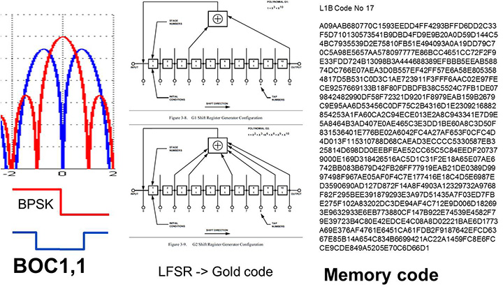
The changed characteristics in Galileo that drove hardware upgrades are shown in Figure 1. The binary offset carrier BOC(1,1) modulation stretches the bandwidth, affecting the RF, while both the BOC and the memory codes affect the baseband silicon in the code-generator area.
Figure 1. Changes for Galileo.
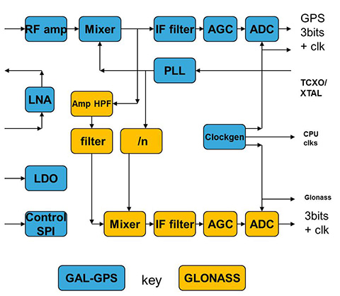
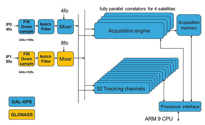
Next was the return to strength of the GLONASS constellation, meaning receivers were actually needed before Galileo. However the different center frequency (1602 MHz), and the multi-channel nature of the FDMA meant more major changes to the hardware. As shown in Figure 2 in orange, a second mixer was added, with second IF path and A/D converter.
Figure 2. Teseo-2 RF hardware changes for GLONASS.Figure 3. Teseo-2 and Teseo-3 baseband changes for GLONASS.
The baseband changes added a second pre-processing chain and configured all the acquisition channels and tracking channels to flexibly select either input chain. Less visible, the code-generators were modified to support 511 chip codes and 511kchips/sec rates.
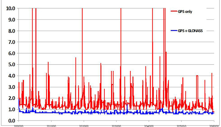
Teseo-2 appeared with GPS/GLONASS support in 2010, and demonstrated the benefit of GNSS in urban canyons, as shown by the dilution of precision (DOP) plot for central London in Figure 4. The GPS-only receiver (in red) has frequent DOP excursions beyond limits, resulting either in bad accuracy or even interrupted fix availability. In contrast, the GNSS version (in blue) has a DOP generally below 1, with a single maximum of 1.4, and thus 100 percent availability. Tracking 16 satellites, even if many are via non-line-of-sight (NLOS) reflected paths, allows sophisticated elimination of distorted measurements but still continuous, and hence accurate, positioning.
Figure 4. DOP/accuracy benefits of GNSS.
BeiDou
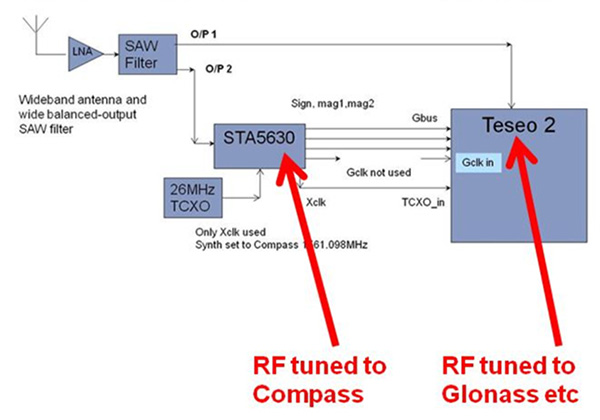
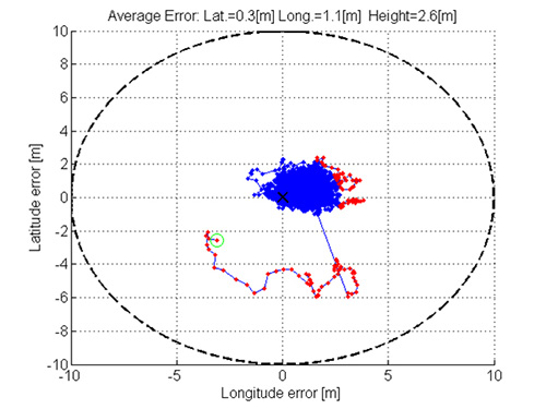
Like Galileo, BeiDou is a story of chapters. Chapter 1 was no ICD, and running on a demo dual-RF architecture as per the schematic shown in Figure 5. Chapter 2 was the same hardware with the test ICD, so all satellites, but still no positioning. Chapter 3 was the full ICD giving positioning in January 2013 (Figure 6), then running on the real Teseo-3 silicon in September 2013, shown in Figure 7.
Figure 5. Demo Teseo-2 dual RF implementation of BeiDou.Figure 6. Beidou positioning results.Figure 7. Teseo 3 development board.
The Teseo-3 has an on-chip RF section capable of GPS, Galileo, GLONASS and BeiDou, so no external RF is needed.
The clear green space around the Teseo-3 chip in the photo and the four mounting holes are for the bolt-down socket used to hold chips during testing, while the chip shown is soldered directly to the board. Figure 8A shows the development board tracking eight BeiDou satellites visible from Taiwan.
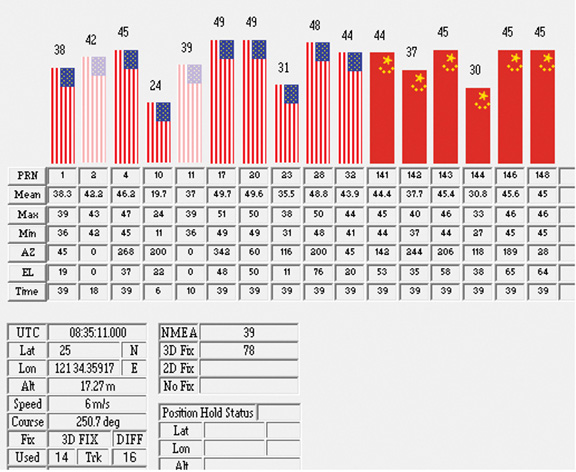
However, the silicon is not designed to be single-constellation; it is designed to use all the satellites in the sky. Figure 8b shows another test using GPS and BeiDou satellites simultaneously.
Figure 8A. Beidou.Figure 8b. GPS+Beidou.
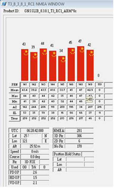
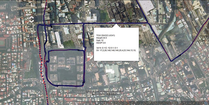
A mobile demo on the Teseo-3 model is shown running GPS plus BeiDou in Figure 9, a road test in Taipei. Satellites (SV) up to 32 are GPS, those over 140 are BeiDou, in the status window shown: total 13 satellites in a high-rise city area, though many are non-LOS.
Figure 9. GPS + Beidou roadtrack in Taipei.
Extending the hardware to add BeiDou, which is on 1561 MHz and thus a third center frequency, meant adding another path through the IF stages of the on-chip radio. After the first mixer, GPS is at 4 MHz, and GLONASS at about 30 MHz, but BeiDou is at minus 10 MHz. While the IF strip in general is real, rather than complex (IQ), the output of the mixer and input to the first filter stage is complex, and thus can discriminate between positive frequencies (from the upper sideband) and negative ones (from the lower sideband), and this is normally used to give good image rejection. In the case of BeiDou, the filter input is modified to take the lower sideband, that is, negative frequencies, and a second mixer is not required; the IF filter is tuned to 10 MHz. The new blocks for BeiDou are shown in green in Figure 10. The baseband has no new blocks, but the code generator has been modified to generate the BeiDou codes (and, in fact, made flexible to generate many other code types and lengths). Two forms of Teseo-3 baseband are envisaged, the first being for low-cost, low-current continues to have two input paths, so must choose between GLONASS and BeiDou as required. A future high-end model may have an extra input processing path to allow use of BeiDou and GLONASS simultaneously.
Figure 10. Teseo-3 RF changes for Beidou shown in green.
Galileo Again
Maintaining the chronological sequence, Galileo gets a second chapter in three steps. In December 2012, it was possible for the first time to track four IOV satellites simultaneously, though not to position due to the absence of valid orbit data. In March 2012, it was possible for the first time to demonstrate live positioning, and this was done using Teseo-2 simultaneously by ESA at ESTEC and STMicro in Naples and Milan, our software development centres.
The demos were repeated in public for the press on July 24, 2013, at Fucino, Italy’s satellite earth station, with ESA/EC using the test user receiver (TUR) from Septentrio, and ST running simultaneous tests at its Italian labs. Figure 11 and Figure 12 show the position results for the data and pilot channels respectively, with independent LMS fixes. In real life, the fixes would be from a Kalman filter, and would be from a combined E1-B/E1-C channel, to take advantage of the better tracking on the pilot.
Good accuracy is not expected from Galileo at this stage. The four satellites, while orbited to give good common visibility, do not also give a good DOP; the full set of ground monitoring stations is not yet implemented and cannot be well calibrated with such a small constellation. Finally, the ionospheric correction data is not yet available. Despite these problems, the residuals on the solutions, against a known fixed position for the rooftop antenna, are very respectable, shown in Figure 13.
Figure 13. Galileo residuals, L1-B.
The common mode value is unimportant, representing only an offset in the receiver clock, and 10 meters is about 30 nanoseconds. The accuracy indicator is the spread between satellites, which is very respectable for a code-only receiver without full iono correction, especially around 640 on the TOW scale, where it is less than 2 meters. The rapid and major variation on the green data around t=400 is considered to be multipath, as the roof antenna is not ideally positioned with respect to other machinery and equipment also installed on the roof.
QZSS and GPS-III/L1C
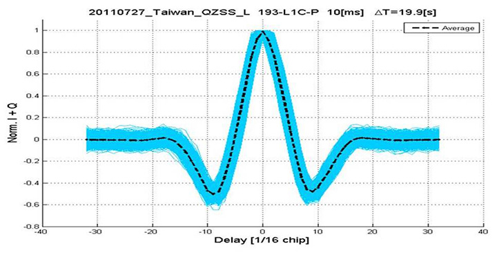
Teseo-2 has supported the legacy (C/A code) signal on QZSS for some time, but Teseo-3 has been upgraded to handle the GPS-III/L1-C signal, waiting for modernized GPS. This signal is already available on the QZSS satellite, allowing tests with real signals. Significant changes were required in the baseband hardware, as the spreading code is a Weill code, whose generation complexity is such that it is generated once when the satellite is selected, then replayed real time from memory. Additionally it is long, in two domains. It is 10230 chips — that is, long to store but also long in time, with a 10-millisecond epoch. On Teseo-3, the legacy C/A code is used to determine code-phase and frequency before handing over to the Weill code for tracking.
Using a long-range crystal ball and looking far into the future, a model of the future Teseo-4 DSP hardware is available, with 64 correlation taps per satellite. Running this on the captured QZSS L1-C signal gives the correlation response shown in Figure 14. Having multiple taps removes all ambiguity from the BOC signal, simultaneously removing data transitions, which can alternatively be pre-stripped using the known pilot secondary code (which on GPS III is 5 dB stronger than the data signal). The resultant plot represents 2,000 epochs, each of 10 milliseconds, plotted in blue, with integrated result for the full 20 seconds shown in the black dashed line. Assuming vehicle dynamics is taken out using carrier Doppler, this allows extremely precise measurement of the code phase, or analysis of any multipath in order to remove it. This RF data was captured on a benign site with a static antenna, so it shows little distortion.
Figure 14. L1-C tracking on QZSS satellite.Figure 15. Dual RF implementation of dual-band front end.
The Future
Having already built in extreme flexibility to the code generators to support all known signals and generalized likely future ones, the main step for the future is to support multiple frequencies, starting with adding L5 and/or L2, but as before, ensuring that enough flexibility is built in to allow any rational user/customer choice. It is not viable for us to make silicon for low-volume combinations, nor to divide the overall market over different chips. Thus our mainstream chip must also support the lower volume options.
We cannot, however, impose silicon area or power consumption penalties on the high-volume customer, or he will not buy our product.
Thus, our solution to multi-frequency is to make an RF that can support either band switchably, with the high band integrated on the volume single-chip GNSS. Customers who also need the low band can then add a second RF of identical design externally, connected to the expansion port on the baseband, which has always existed for diagnostic purposes, and was how BeiDou was demonstrated on T2. By being an RF of identical design to the internal one, it incurs no extra design effort, and would probably be produced anyway as a test chip during the development of the integrated single-chip version. Without this approach, the low volume of sales of a dual-band radio, or a low-band radio, would never repay its development costs.
Conclusions
All four constellations have been demonstrated with live satellite signals on Teseo-2, a high-volume production chip for several years, and on Teseo-3 including use in combinations as a single multi-constellation positioning solution. With the advent of Teseo-3, with optimized BeiDou processing and hardware support for GPS-3/L1C, a long-term single-chip solution is offered.
For the future, dual-frequency solutions are in the pipeline, allowing full advantage of carrier phase, and research into moving precise point positioning and real-time kinematic into the automotive market for fields such as advanced driver-assistance systems.
Acknowledgments
Teseo III design and development is supported by the European Commission HIMALAYA FP-7 project.
This article is based on a technical paper first presented at ION-GNSS+ 2013 in Nashville, Tennessee.
ST GPS products, chipsets and software, baseband and RF are developed by a distributed team in: Bristol, UK (system R&D, software R&D; Milan, Italy (Silicon implementation, algorithm modelling and verification); Naples, Italy (software implementation and validation); Catania, Sicily, Italy (Galileo software, RF design and production); Noida, India (verification and FPGA). The contribution of all these teams is gratefully acknowledged.
Philip G. Mattos received an external Ph.D. on his GPS work from Bristol University. Since 1989 he has worked exclusively on GNSS implementations, RF, baseband and applications. He is consulting on the next-generation GNSS chips, including one-chip GPS (RF+digital), and high-sensitivity GPS and Galileo for indoor applications, and combined GPS/Galileo/GLONASS chipsets. In 2008-2009, he re-implemented LORAN on the GPS CPU, and in 2009-2010 led the GLONASS implementation team. He is leading the team on L1C and BeiDou implementation, and the creation of totally generic hardware that can handle even future unknown systems.
Fabio Pisoni has been with the GNSS System Team at STMicroelectronics since 2009. He received a master’s degree in electronics from Politecnico di Milano, Italy, in 1994. He was previously with the GNSS DSP and System Team in Nemerix SA and has earlier working experience in communications (multi-carrier receivers).