GIS map provider Mapmechanics has boosted the number of African countries for which it offers HERE vector (scalable) map data.
HERE mapping from Mapmechanics consists of street-level vector map and includes major highways, main roads and also some minor roads and city streets, and is useful for route planning, drive-time analysis, vehicle tracking and geo-demographics. A key feature of the data is that its structure is consistent across many countries, enabling users to adopt the same analytical and display strategies from one country to another.
The new African countries added to the Mapmechanics portfolio are Cameroon, Cape Verde, Central African Republic, Chad, Democratic Republic of the Congo, Equatorial Guinea, Ethiopia, Gabon, Guinea-Bissau, Republic of the Congo, São Tome and Principe.
Because it is in a standard and widely recognized format, the mapping lends itself well to use with other data such as traffic speed and density where this is available. It can also be used for techniques such as reverse geocoding (finding a location by its coordinates).
The mapping also enables users to add a sense of place to activities such as geo-demographic studies, store location analysis, leaflet distribution territories or depot management, and ensures that users can overlay just the features they need on shaded maps.
Mapmechanics already offers HERE mapping for many of the more prominent African countries, including for instance Botswana, Egypt, Kenya, Mozambique, South Africa and Tunisia. Altogether around two dozen African countries are now covered, and more will be added in future.
HERE mapping is just one of a wide range of mapping products offered by Mapmechanics for the UK and the world, all of which can be obtained directly from the company or through its transactional website.
Volvo Cars has a complete system solution that makes it possible to integrate self-driving cars into real traffic, with ordinary people in the driver’s seat. The automaker presented its planned system in an online press conference Feb. 19.
“We are entering uncharted territory in the field of autonomous driving,” said Peter Mertens, senior vice president of Research and Development, Volvo Car Group. “Taking the exciting step to a public pilot, with the ambition to enable ordinary people to sit behind the wheel in normal traffic on public roads, has never been done before.”
As the Drive Me project enters its second year, Volvo is moving toward its goal of placing 100 self-driving cars in the hands of customers on selected roads around Gothenburg by 2017. The public pilot — a collaboration between legislators, transport authorities, a major city and a vehicle manufacturer — is a central component of Volvo’s plan to achieve sustainable mobility and ensure a crash-free future.
Early prototype cars are now being tested on the DriveMe route in and around Gothenburg, Sweden.
Volvo’s production-viable autonomous driving system is based on a complex network of sensors, cloud-based positioning systems and intelligent braking and steering technologies.
“Autonomous driving will fundamentally change the way we look at driving. In the future, you will be able to choose between autonomous and active driving,” Mertens said. “This transforms everyday commuting from lost time to quality time, opening up new opportunities for work and pleasure.”
Volvo’s autopilot system is designed to be reliable enough to allow the car to take over every aspect of driving in autonomous mode, Volvo said. The technology advances a crucial step beyond the automotive systems demonstrated so far since it includes fault-tolerant systems, the carmaker said.
“It is relatively easy to build and demonstrate a self-driving concept vehicle, but if you want to create an impact in the real world, you have to design and produce a complete system that will be safe, robust and affordable for ordinary customers,” said Erik Coelingh, technical specialist at Volvo Cars.
The main challenge is to design an autopilot that is robust for traffic scenarios as well as for technical faults that may occur. The driver can’t be expected to suddenly intervene in a critical situation. Initially, the cars will drive autonomously on selected roads with suitable conditions, such as without oncoming traffic, cyclists or pedestrians.
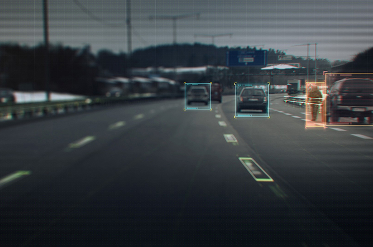
Volvo’s system generates exact positioning and a complete 360° view of the car’s surroundings through a combination of radars, cameras and laser sensors. A network of computers processes the information, generating a real-time map of moving and stationary objects in the environment.
“Making this complex system 99 percent reliable is not good enough. You need to get much closer to 100 percent before you can let self-driving cars mix with other road users in real-life traffic,” Coelingh said. “Here, we have a similar approach to that of the aircraft industry. Our fail-operational architecture includes backup systems that will ensure that the autopilot will continue to function safely if an element of the system were to become disabled.”
For example, the probability of a brake system failure is very small, but a self-driving vehicle needs a second independent system to brake the vehicle to a stop, because it is unlikely that the driver will be prepared to press the brake pedal.
On the road, the complete technology solution is designed to handle even the most complicated scenarios, from smooth commuting to heavy traffic and emergency situations, Volvo said. “Just as good drivers would, potentially critical situations are approached with sensible caution. In a real emergency, however, the car reacts faster than most humans,” Coelingh said.
When autonomous driving is no longer available — because of weather, technical malfunction or the end of the route has been reached — the driver is prompted by the system to take over again. If the driver is incapacitated for any reason and does not take over in time, the car will bring itself to a safe place to stop.
Volvo expects that autonomous driving could cut fuel consumption, improve traffic flow, and open up possibilities for urban planning and more cost-efficient investments in infrastructure.
“Developing a complete technological solution for self-driving cars is a major step. Once the public pilot is up and running, it will provide us with valuable knowledge about implementing self-driving cars in the traffic environment, and help us explore how they can contribute to sustainable mobility,” Coelingh said. “Our smart vehicles are a key part of the solution, but a broad societal approach is vital to offer sustainable personal mobility in the future. This unique cross-functional cooperation is the key to a successful implementation of self-driving vehicles.”
Drive Me system components:
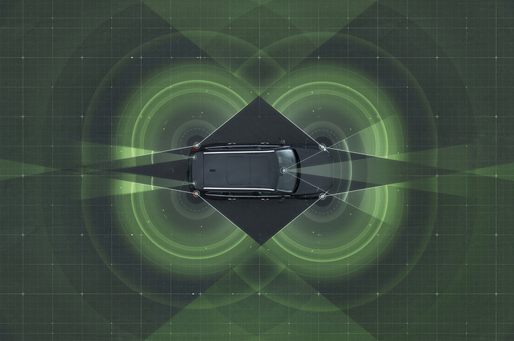
The 76-GHz frequency-modulated, continuous wave radar is placed in the windscreen and combined with a camera to detect objects on the road. Four radars behind the front and rear bumpers locate objects in all directions. Long-range radars in the rear ensure a good rearward detection of vehicles in parallel lanes.
Sensor technologies. Volvo Cars is developing a holistic solution that generates exact positioning and a complete 360-degree view of the car’s surroundings. This is achieved by a combination of multiple radars, cameras and laser sensors. A redundant network of computers processes the information, generating a real-time map of moving and stationary objects in the environment.
Precise positioning is based on this surround information together with GPS and a high-definition 3D digital map that is continuously updated with real-time data. The system is reliable enough to work without requiring driver supervision.
Combined radar and camera. The combined 76-GHz frequency-modulated continuous wave radar and camera placed in the windscreen is the same as that in the new XC90. This system reads traffic signs and the road’s curvature and can detect objects on the road such as other road users.
Surround radars. Four radars behind the front and rear bumpers (one on each corner of the car) are able to locate objects in all directions. By sweeping both left and right, transmitting waves that bounce off signs, poles, and tunnels, they monitor a full 360-degree around the car.
360-degree surround vision. Four cameras monitor objects in close proximity to the vehicle. Two are under the outer rear-view mirrors, one is in the rear bumper and one is in the grille. Besides detecting objects at close range, these cameras monitor lane markings. The cameras have a high dynamic range and can handle quick changes in lightning conditions, such as when entering a tunnel.
Multiple beam laser scanner. This sensor system is placed in the front of the vehicle, below the air intake. The scanner can identify objects in front of the car and ensures very high angle resolution. It can also distinguish between objects. The laser sensor has a range of 150 meters for vehicles and covers a 140-degree field of view.
Trifocal camera. A trifocal camera placed behind the upper part of the windscreen is three cameras in one, providing a broad 140-degree view, a 45-degree view and a long-range, yet narrow, 34-degree view for improved depth perception and distant-object detection. The camera can spot suddenly appearing pedestrians and other unexpected road hazards.
Long-range radars. Two long-range radars placed in the rear bumper of the car ensure a good rearward field of view. This technology is useful when changing lanes because it can detect fast-moving vehicles approaching from far behind.
Ultrasonic sensors. Twelve ultrasonic sensors around the car are used to identify objects close to the vehicle and support autonomous driving at low speeds. The sensors are based on the technology used for current park-assist functions enhanced with advanced signal processing. This technology is useful for detecting unexpected situations, such as pedestrians or hazards on the road close to the car.
High-definition 3D digital map. A high-definition 3D digital map provide the vehicle with information about the surroundings, such as altitude, road curvature, number of lanes, geometry of tunnels, guard rails, signs, and exits. The position geometry is in many cases at centimeter level.
High-performance positioning. The high-performance GPS is one part of the positioning control that is enhanced by a combination of an advanced GPS, a three-degrees-of-freedom accelerometer and a three-degrees-of-freedom gyro. By matching the 360-degree image created by the multitude of sensors with the map image, the car will get the information about its position in relation to the surroundings.
By combining the information from the sensors and the map, the Drive Me car is able to choose the best course in real time, factoring in variables such as the curvature of the road, speed limit, temporary signs and other traffic.
Cloud services. The cloud service is connected to the traffic authorities’ control center. This ensures that the most up-to-date traffic information is always available. Control center operators also have the ability to tell the drivers to turn off the autonomous drive mode if necessary.
Pitney Bowes Inc. has entered into a multi-year partnership with INRIX, Inc., provider of traffic information and driver services, to deliver advanced location intelligence solutions through the company’s traffic intelligence platform.
By integrating location capabilities with traffic analysis, INRIX and Pitney Bowes will enhance the driving experience of today’s connected drivers, the companies said. By delivering this information through INRIX’s mobile app, users are empowered to make better location-based decisions in real-time.
“Pitney Bowes’ location intelligence solutions can add compelling new capabilities to the existing products of mobile-oriented companies such as INRIX,” said James Buckley, Senior Vice President and General Manager, Location Intelligence, Pitney Bowes. “Our products help unearth non-obvious relationships between specific locations to improve the customer experience and drive loyalty.”
INRIX has designed a leading traffic intelligence platform that uses smart data and advanced analytics to solve transportation issues worldwide. The company uses a unique approach called “smart crowd-sourcing” that analyzes real-time traffic speed and incident data from a wide variety of public and private traffic sources ranging from road sensors and up-to-the-minute traffic speeds and community reports crowd-sourced from millions of vehicles and mobile devices throughout the day. Whether through an in-car or smartphone navigation application, a local newscast or the company’s INRIX Traffic app, INRIX offers up-to-the-minute traffic information and other driver services to help more than 150 million drivers save time, fuel and money.
Pitney Bowes Location Intelligence solutions merge organizational data with location data to provide users with the capability to make more informed decisions. For INRIX, this technology compiles and correlates addresses with coordinates from a mobile device to establish real-time location or a desired destination. Combining that with other data such as specific traffic flow, demographics and behavior patterns, users can uncover key points of interest by accessing Pitney Bowes advanced location search. For example, if a consumer is planning to visit a popular department store in a specific region, the technology makes it possible to suggest a relevant restaurant recommendation for lunch, based on the data that is collected about user preferences, convenience, proximity and projected traffic patterns.
“INRIX had a number of compelling reasons to partner with Pitney Bowes,” said Scott Sedlik, Vice President, Product Planning and Market Development for INRIX. “Our customers are looking to make real-time decisions using location data, and Pitney Bowes has the most comprehensive suite of offerings to fulfill that need. Other key reasons for teaming include a strong customer focus and alignment with our own strategic goals and approach.”
GPSTrackIt.com has introduced a new Driver Safety Alert that tracks hard turns. Driver Safety Alerts already track and report driving behaviors like rapid acceleration, hard braking, and seatbelt usage. GPSTrackIt engineers have now added the ability to identify “hard turns” to the alert list.
Driver Safety Alerts are used by businesses across the country to help dispatchers and managers understand how drivers are doing in the field. Businesses ranging from small-to-medium sized service companies to large transportation companies with fleets of hundreds of vehicles are able to help drivers understand the importance of safe driving behaviors.
“Drivers represent their employers to the public,” said Eddie Bermudez, GPSTrackit.com’s product development manager. “A vehicle that is driven badly or, more to the point, dangerously, does not reflect well on that employer. These alerts notify managers and dispatchers via email or SMS text messages when their drivers are driving in a potentially aggressive manner.”
Rapid acceleration and hard braking are indicators of bad driving behaviors that also impact a vehicle’s mileage. Seat belt alerts indicate that the vehicle is moving while the driver’s seat belt is unfastened. Statistics show that wearing a seatbelt dramatically reduces deaths and injuries from collisions.
“Hard turns are another driving behavior that puts the driver and vehicle at additional risk,” continued Bermudez. “It also puts additional wear on a vehicle. We were able to utilize the accelerometer and gyroscope technologies built into the GPS tracking devices in a similar manner to the hard braking alert.”
According to the National Transportation Highway Safety Administration’s 2008 report to Congress, “National Motor Vehicle Causation Crash Survey,” about 36 percent of vehicles involved in collisions were turning or crossing at intersections just prior to the crashes.
“When we’re making a turn, we become more vulnerable,” added Bermudez. “Clearly in a left turn situation you’re putting your vehicle in the path of oncoming traffic. But right turns can be hazardous as well to both pedestrians and drivers. Turn too soon and you clip the curb, which doesn’t do much for your wheel alignment. Turn too late and you could end up making a wide turn. If the device on the vehicle transmits a hard turn event, Fleet Manager checks if an alert is configured for that vehicle. If so, it sends the time, date, and location information to the email and/or text recipients.”
Ford is studying communications between space robots and Earth to enhance future applications of the connected-car communications protocol. The research furthers the company’s commitment to the development of connected vehicle communications to help reduce traffic congestion and aid in the advancement of emergency vehicle communication methods, Ford said.
Ford has launched a three-year research partnership with the telematics department of St. Petersburg Polytechnic University in Russia in its association with that country’s space industry. The goal is to analyze space-based robotic communications systems for vehicle mesh networks to aid in mobility solutions.
The development of connected vehicle communications has the potential to reduce traffic accidents and ease congestion by enabling vehicles to communicate with each other, and to communicate with buildings, traffic lights, the cloud and other systems to deliver a message or detect and respond to imminent collision warnings.
All major international car-makers are installing telematics units, sending a signal that wireless information and connectivity is here to stay in the vehicle, and location will be a big part of the growth. To learn more about the rapid changes in the connected vehicle field, tune in to our September 19 webinar, hosted by Wireless LBS editor Janice Partyka. Registration is free.
“Ford has been committed to the research and development of connected vehicle communications for more than a decade,” said Paul Mascarenas, chief technical officer and vice president, Ford research and innovation. “Our participation in this research can aid in the development of next-generation Ford driver-assist technologies. These technologies will globally benefit Ford customers, other road users and the environment.”
Emergency Situations. One promising development from Ford’s research project with St. Petersburg Polytechnic University is the advancement in emergency vehicle communication methods. Ford is analyzing how emergency messages should be sent to ensure delivery if network failures were to occur, identifying the systems and methods that provide redundancy in case of primary delivery failure.
For example, if an accident were to cause vehicle-to-cloud communications (V2C) to be broken, a vehicle may still have access to a vehicle-to-vehicle (V2V) communications network. An emergency signal message could potentially be sent through V2V to a vehicle nearby, and then between vehicles and infrastructures until it reached EMS.
“The research of fallback options and robust message networks is important,” said Oleg Gusikhin, technical leader in systems analytics for Ford. “If one network is down, alternatives need to be identified and strengthened to reliably propagate messages between networks.”
Space Telematics. Telematics — the long-distance transmission of digital information — developed for use on space stations provide excellent potential for improving the reliability of future vehicle-to-cloud, vehicle-to-infrastructure, vehicle-to-vehicle and other forms of communication (V2X). The communications blend multiple networking technologies including dedicated short-range communication (DSRC), cellular LTE wireless broadband and mesh networking to ensure robust and reliable connectivity for optimum signal strength for critical messages.
Using the knowledge accrued from analyzing the space robots, Ford engineers could then develop an algorithm that is integrated into the V2X system resulting in a message that would route through the appropriate network depending on the level of its importance. An emergency message, for example, may be communicated through the faster mesh network, whereas an entertainment-related message would route through a vehicle-to-infrastructure application, an embedded device or a brought-in device network.
“We are analyzing the data to research which networks are the most robust and reliable for certain types of messages, as well as fallback options if networks were to fail in a particular scenario,” said Oleg Gusikhin, technical leader in systems analytics for Ford. “In a crash, for example, a vehicle could have the option to communicate an emergency though a DSRC, LTE or a mesh network based on the type of signal, speed and robustness required to reach emergency responders as quickly as possible.”
Here is a video showing how Ford is studying space robot communications.
Findings from this work could potentially enhance Ford’s wireless communication technologies and Blueprint for Mobility. Ford’s Blueprint for Mobility details the company’s vision on how to tackle the issues of mobility in an increasingly crowded and urbanized planet between now and 2025.
TomTom announces its annual 2012 Congestion Index, a report comparing congestion levels in 2012 versus 2011 in 161 cities and across five continents. The Annual Congestion Index finds Moscow the most congested city.
According to the announcement, on average, journey times in Moscow are 66% longer during non-congested periods when traffic is flowing freely, and 106% longer during morning rush hour. TomTom’s Congestion Index, including individual continent and city reports, can be found at www.tomtom.com/congestionindex.
TomTom’s Congestion Index is a barometer of congestion in urban areas. The Index is uniquely based on real travel time data captured by vehicles driving the entire road network. TomTom’s traffic database contains over six trillion data measurements and is growing by five billion measurements every day.
The top ten most congested cities, ranked by overall Congestion Level, in 2012 are:
1. Moscow 66%
2. Istanbul 55%
3. Warsaw 42%
4. Marseille 40%
5. Palermo 39%
6. Los Angeles 33%
7. Sydney 33%
8. Stuttgart 33%
9. Paris 33%
10. Rome 33%
“TomTom’s Annual Congestion Index provides accurate insight into the world’s most congested cities,” said Ralf-Peter Schäfer, Head of Traffic at TomTom. “This detailed knowledge of the entire road network helps businesses and governments to make more informed decisions about how best to tackle, and avoid congestion. TomTom’s world-class traffic information also helps drivers get to their destinations faster. Significantly, when used on a large scale, TomTom HD Traffic has the potential to ease congestion in cities and urban areas by routing drivers away from congested areas.”
About the TomTom Congestion Index
The methodology used in the Congestion Index compares measured travel times during non-congested periods (free flow) with travel times in peak hours. The difference is expressed as a percentage increase in travel time. The Index takes into account local roads, arterials, as well as highways. All data is based on actual GPS based measurements.
As well as assigning and ranking the overall congestion levels of over 161 cities around the world, the report analyses the congestion levels in cities at different times of the day and on different days of the week. TomTom analysed capital cities as well as cities with a population of over 800,000. In addition, a selection of key cities with smaller populations was included based on their regional importance to the transportation network. The purpose of adding these smaller cities was to provide a better understanding of congestion levels within individual countries.
Individual city reports include more detailed information such as the most congested day, time delay per year for commuters and congestion levels on main and secondary roads.
The Federal Motor Carrier Safety Administration (FMCSA) will begin issuing official recommendations to members of the commercial trucking industry on the proper uses of GPS devices and incorporate GPS training into new entry-level certification programs for commercial motor vehicle operators.
U.S. Senator Chuck Schumer, joined by Administrator Anne Ferro of the U.S. Department of Transportation Federal Motor Carrier Safety Administration (FMCSA), held two press conferences in the New York City area on March 11 to alert commercial vehicle drivers to the importance of using updated, professional-quality GPS devices to prevent routes that include height-restricted overpasses and bridges.
Administrator Ferro also announced the availability of a GPS safety visor card for truck and bus drivers, now downloadable at www.fmcsa.dot.gov (and pictured above).
Under the recommendations, commercial drivers will be trained, and reminded, to only use GPS systems designed specifically for the industry. These specialized units take into account the specifics of the truck they’re in — including the height, weight and contents — and will then route the trucks onto appropriate roads. The consumer GPS units too often being used are frequently routing trucks onto inappropriate roads, causing them to crash into low overpasses and bridges.
In September, Schumer called on the Department of Transportation (DOT) to investigate the dramatic increase in low bridge strikes by commercial trucks across New York State as a result of the growing use of GPS by drivers. According to reports from local police organizations, GPS-related bridge strikes in New York represent more than 80 percent of all such accidents. The accidents, in addition to being life threatening, cause massive delays and impose significant costs on taxpayers.
In one press conference, Schumer and Administrator Ferro stood at the Eagle Avenue overpass, which spans the Southern State Parkway at exit 18. The overpass has been struck at least 27 times by trucks that are prohibited from driving on the parkway.
“These education and training campaigns for commercial truck drivers will be the first major steps to thwarting life-threatening bridge strikes that have been causing massive delays and imposing significant costs on taxpayers with increasing frequency in recent years,” said Schumer. “These steps will help to once again make GPS devices an asset to drivers, and not a dangerously misused tool. I am pleased that the DOT heeded my call for reforms and I am confident that the combination of official recommendations and GPS training will limit the number of low-bridge strikes across Long Island. Thank you to FMCSA Administrator Ferro for recognizing the importance of this serious issue and for implementing a proactive approach towards teaching the industry how to eliminate GPS-related accidents.”
“Even one truck or bus striking an overpass is one too many, which is why we’re taking action to ensure professional truck and bus drivers know the importance of selecting the right navigation system,” said FMCSA Administrator Anne Ferro.
Commercial truck traffic is prohibited on New York State Parkways such as the Southern and Northern State Parkways on Long Island, the Hutchinson and Saw Mill Parkways in the Hudson Valley, and the FDR and Bronx River Parkway in New York City. Overpasses constructed over these parkways were built, in some cases, over 50 years ago, and at low heights. Although these parkways consist of numerous warning and directional signs alerting commercial drivers of the dangers, basic GPS devices often do not show these restrictions and funnel trucks into major danger zones.
According to a recent NYS Department of Transportation study, more than 200 bridge accidents per year have occurred in New York since 2005. Of that total, more than 25 percent of these accidents occurred in Nassau, Suffolk or Westchester counties. Major repairs on the Long Island Expressway connected to these types of accidents have cost taxpayers $4.1million in recent years, according to the NYS Department of Transportation.
Researchers at Israel’s Ben-Gurion University of the Negev (BGU) say reveal that data culled from geosocial networks like the GPS traffic app Waze can help prevent traffic incidents with better deployment of police resources at the most accident prone areas.
“Only now are we beginning to discover the potential in the huge amount of data collected daily,” explains BGU researcher and Ph.D. student Michael Fire. “Studies of this kind, which monitor events such as traffic accidents over time, can help the police identify dangerous sections of roads in real time, or alternatively, locations where few police are needed.”
The paper, “Data Mining Opportunities in Geosocial Networks for Improving Road Safety,” was presented at the IEEE 27th Convention of Electrical and Electronics Engineers in Israel.
Waze records location data and enables users to upload and share comments on any detail, including traffic alerts, accidents or police presence. According to its website, Waze has 30 million worldwide users and describes itself as “a community-based traffic and navigation app whose users share real-time traffic and road info, saving time and gas money.”
Using Waze data and Google Earth, the BGU researchers determined that three-quarters (75 percent) of the locations in Israel with the highest number of accidents were intersections. They then analyzed references to a police presence to determine if the police were present at the spots that had the worst traffic accidents.
“There were numerous instances where the police were manning quieter intersections, while busier intersections went unmonitored,” Fire explains. “According to the data, police response time varied from 20 minutes to 40 minutes in some situations.”
Using Waze, data from May and June 2012 was collected and analyzed on accident reports, police presence, traffic jams, and speed traps. BGU researchers identified 579 different locations in Israel that had at least five reoccurring accidents during this time where 5,156 reported accidents occurred. Police were reported at least 15 times at more than 3,500 locations.
Other researchers involved with the study from BGU’s Department of Information Systems Engineering and BGU’s Telekom Innovation Laboratories include Prof. Yuval Elovici, head of the lab, as well as Dr. Rami Puzis, Prof. Lior Rokach as well as student Dima Kagan.
CE-Traffic, a traffic data provider in Central-Eastern Europe, has extended its portfolio of traffic services in Poland, the country where over last five years the number of vehicles has grown by 50 percent. Drivers in Poland can look forward to more options in receiving real-time traffic information with the launch of the new Premium RDS-TMC service by CE-Traffic, the company said.
“We looked at TMC solution with all its limitations and asked ourselves: how we can get more out of the technology that has been around for more than a decade so that navigation systems vendors can offer to their customers an easy-to-implement and affordable traffic service of a real value? Our Premium RDS- TMC offers drivers an access to very detailed traffic information without any mobile telecommunication cost and subscription fees,” said Jiri Novobilsky, CEO of CE-Traffic.
Competitive advantage of CE-Traffic Premium RDS-TMC is based on smart use of TMC components, according to CE-Traffic. Up-to-date traffic flow data and journalistic information are smartly aggregated and regionally filtered. CE- Traffic TISA certified Location Table (LTN 6) offers the best available coverage. It includes not only all major roads and streets but also lower category roads commonly used by drivers like shortcuts or alternative routes. RDS channel with enhanced capacity allows broadcasting high number of traffic messages (over 1,000). The service is available country-wide thanks to partnership with Radio ZET – leading Polish radio station.
Tomasz Przeździęk, CE-Traffic director for Poland, added: “When looking at overall traffic offering for personal and in-car navigation systems in Poland one can see that expensive connected devices did not achieve the major market acceptance. Proven TMC standard together with high quality CE-Traffic Floating Car Data is an easy to implement alternative to provide drivers with the most accurate and up-to-date traffic information.”
INRIX, a provider of traffic information and driver services, has introduced a new app for the iPhone and iPad that helps drivers take control of their commute and avoid traffic. The company said that INRIX Traffic helps cut the cost of gridlock with the following features:
Fastest Routes to Home and Work: Drivers can easily decide which route is the best choice to get around traffic, as the app analyses the effect accidents, sporting events, concerts, and other events have on traffic to deliver the fastest routes with the least delay.
Recommended Departure and Travel Times: The INRIX Traffic Forecast Slider shows drivers the best options for avoiding frustrating delays now and in the future.
Share INRIX Arrival Times: Users can send their INRIX Arrival Time instantly to any contact with just a few taps.
Personalized Traffic Alerts: Drivers can tune their app to alert them to accidents and other incidents causing delays along their route.
“We’re putting 100 million traffic reporters into the palm of your hand,” said Kevin Foreman, INRIX vice president of Consumer Applications. “Our latest release helps drivers never be late again.”
The new INRIX Traffic App is available as a free, ad-free download for iPhone; iPad and iPod Touch from the Apple App Store.
Telmap announced that Telmap will use INRIX’s real-time, historical and predictive traffic information in its Mobile Location Companion service worldwide.
According to the announcement, the partnership is expected to enhance the navigation experience and increase usage by allowing Telmap users to enjoy best in class routing through better alternative routes that take into consideration real-time traffic and will result in reduced travel time and more accurate estimated time of arrival (ETA). These improvements will be driven by INRIX’s breakthrough traffic analytics that accurately measure the speed of travel and estimate travel times for routes covering both major motorways and secondary roads, which is powered by the largest crowd-sourced traffic community in the world. INRIX’s traffic data coverage combined with the coverage of recently acquired ITIS Holdings offers Telmap users unprecedented coverage in 30 countries.
“Telmap’s goal is to provide its millions of users with an excellent and the quickest possible navigation experience. We evaluated several traffic data providers and INRIX’s excellent aggregation and technological capabilities, extensive coverage, and focus on traffic as their main product, will enable us to present the best traffic available in the world today”, said Motti Kushnir, Telmap Chief Marketing Officer.
“Telmap are a strategically important customer to INRIX,” said Stuart Marks, Senior Vice President of INRIX Europe. “Our efforts to combine the immediacy of community traffic reporting with our existing data will result in the delivery of critical information to the driver in a much more timely manner than available from other services today.”
Telmap reports that INRIX traffic information will be integrated into the Telmap Mobile Location Companion by the end of the year.
An Assisted-GNSS Solution Uses the EGNOS Data Access Service
By Kevin Sheridan, Tomas Dyjas, Cyril Botteron, Jérôme Leclère, Fabrizio Dominici, and Gianluca Marucco
For use in billing drivers in road-user charging schemes, onboard units employing GNSS must meet stringent reliability and availability requirements, and at the same time, be based on low-cost equipment systems. The SIGNATURE unit includes an assistance service which provides ephemeris data and corrections from EDAS, optimized for user location.
As roads become more congested, governments and regional authorities seek better ways to manage their existing networks. Road-user charging (RUC) is increasingly promoted to tackle the congestion challenge: charging drivers a fee, perhaps on a monthly billing basis, derived from the distance their vehicles have traveled, time of travel, and whether congested roads were used.
Recording trip information with a GNSS receiver in an onboard unit (OBU) provides a convenient and flexible means to support automated fee collection. For GNSS positioning to be used as the basis for billing drivers, however, it must meet stringent reliability and availability requirements, and at the same time be based on low-cost equipment.
We have developed a prototype to provide both the positioning availability and integrity required for this application. The Simple GNSS Assisted and Trusted Receiver (SIGNATURE) includes an assistance service that provides ephemeris data and corrections from the European Geostationary Navigation Overlay Service (EGNOS) Data Access Service (EDAS), optimized for the user location. Assistance messages are sent to OBUs that can either host an experimental receiver or a commercial-off-the-shelf (COTS) receiver. Data from the receiver is processed with application-specific navigation algorithms on the OBU that aim to improve the integrity of the position solution relative to standard solutions.
Field trials have assessed the contribution that assistance can make to positioning performance, and illustrate options for enhancing standard assistance solutions. Enhancements to assistance encompass modifications to the message content and alternative means of communications, showing the benefits and feasibility of a broadcast service. The impact of including EGNOS corrections through a broadcast assistance service in urban areas is also under investigation.
GNSS Road-User Charging
RUC has the potential to reduce congestion, lower vehicle emissions, and generate revenue streams for infrastructure improvement. It can ensure that revenues are based on actual road usage, creating a financial incentive for changing driving behavior. This might include lower overall use of private cars and, in particular, reducing peak-time travel levels in urban areas by effectively spreading out the morning and evening rush hour. RUC can also encourage commuters to use alternative forms of public transport.
To automate the process of collecting charges, electronic fee-collection (EFC) systems have been developed based largely on dedicated short-range communications (DSRC). In a DSRC solution, a simple tag on the vehicle receives a signal when it passes a roadside beacon and a charge is computed accordingly. Cameras with automatic number-plate recognition (ANPR) technology are also widely used, mainly as an enforcement tool.
Both technologies rely on fixed roadside infrastructure. As charging schemes to date have focused on specific areas (individual cities) or road infrastructure (major motorways, tunnels, and bridges) this type of technology provides an adequate solution.
To meet future policy goals, however, this is not feasible. More extensive charging schemes covering greater areas, more road types, more classes of vehicle, and which will vary charges depending on location and time of day require a far more flexible solution. Flexible schemes require the positioning element to be onboard the vehicle. GNSS-based devices, possibly augmented with other sensors, have been identified as the best option to achieve this.
Using GNSS, the OBU tracks the location of the vehicle, and this is matched against the road network to calculate a charge. A GNSS solution can support many different charging strategies including time distance and place (TDP) based charging for road sections, geographic areas, and cordon schemes. While GNSS offers great potential, several operational and performance limitations have prevented more widespread adoption. Operationally, OBUs are relatively expensive, fraud prevention is potentially complex, and charging schemes must also accommodate infrequent users. GNSS performance is limited in terms of the ability to provide sufficiently accurate positions with high availability and integrity in all operating conditions.
To be fully flexible and to target congested areas, OBUs must work in all environments including urban areas. Urban-canyon problems, with satellite signals blocked and reflected, are well documented. In some cases, not enough signals are available to determine a position, and when there are enough satellites, the ranges will be prone to errors and the geometry is likely to be poor. Signals are more likely to be available in the longitudinal direction of the street, but with few or no satellites on either side of the vehicle. Signal blockage is a particular problem when the GNSS receiver is started up, and it attempts to decode satellite ephemeris data. This requires around 30 seconds of uninterrupted tracking with a relatively strong signal for each satellite, and in an obstructed urban environment it may take many minutes to determine the first receiver position.
Charging schemes typically aim to charge for at least 99 percent of road usage. If a typical journey length is 30 minutes, this means that only 18 seconds with no usable position solution can be tolerated and hence time to first fix (TTFF) must be below 18 seconds, and ideally much lower.
When positions can be determined, they must be sufficiently accurate to identify the correct road segment that the vehicle was on, and they must be reliable. Reliability, or integrity, becomes critical if road users are to be charged on the basis of GNSS-derived positions. Users must have confidence that they are being charged correctly for schemes to be effective and to gain public acceptance.
Whilst GNSS-based solutions are entering the market, for example in Germany and Slovakia for heavy goods vehicles, barriers to wider adoption remain. Many countries are considering GNSS-based road pricing, and they all face similar challenges in ensuring the accuracy, integrity, and availability of a GNSS-based solution for nationwide deployment.
SIGNATURE Solution
The principal objective of the SIGNATURE project is to prototype a GNSS-based solution for flexible road-user charging that can provide the required high integrity and high availability in a cost-effective and scalable manner.
This robust, high-availability, high-integrity solution is delivered firstly through providing reliable assistance (A-GNSS) data from EDAS to optimize receiver acquisition and tracking capabilities and reduce TTFF, and secondly through implementation of embedded GNSS reliability algorithms into an OBU, providing assurance of positioning information (Figure 1, at top).
These features are intended to make a positive contribution in terms of the key RUC performance criteria, as defined by the GNSS Metering Association for Road User Charging:
Accuracy: right cost per trip
Integrity: probability and amount of overcharging
Availability: amount of charged usage.
Assistance Server. An assistance service supplying suitably equipped OBUs is one means to maintain rapid TTFF and meet the requirement for high positioning availability. The most significant contribution assistance can make to TTFF is to provide the
ephemeris data, which takes around 30 seconds to download from a satellite signal. Assistance data can also reduce the frequency search space when a receiver is acquiring signals, as the expected Doppler frequency can be computed from the approximate receiver and satellite positions.
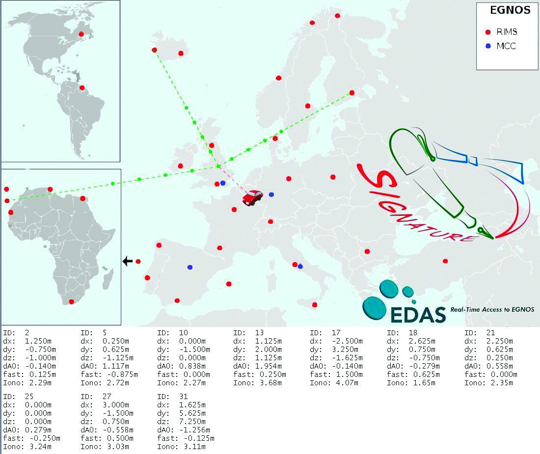
The assistance server in SIGNATURE is based on EDAS, currently available as a beta version. EDAS allows a user to plug into EGNOS to receive the data collected by all the current EGNOS Ranging and Integrity Monitoring Stations (RIMS). This makes it possible to access EGNOS data when there is no clear sight to the EGNOS geostationary satellites, which can often be the case in urban areas, particularly at higher latitudes. As well as supplying EGNOS messages, EDAS also provides GPS observation and navigation (broadcast ephemeris) data, the key component as far as an assistance service is concerned. By recording the ephemeris data received at the extremities of the monitoring network, it is possible to ensure that the current ephemeris for any GPS satellite in view to users over Europe is available and can be supplied in an assistance message. Other data streams provided by EDAS can also be used to enhance the assistance solution.
The main enhancement tested in SIGNATURE was the use of EGNOS corrections within the assistance message. EGNOS today consists of a space segment of three geostationary satellites broadcasting correction and integrity information in the L1 band. Three sets of corrections are broadcast to users:
Fast corrections: used to compensate short-term disturbances in GPS signals, generally attributable to satellite clocks;
Long-term corrections: used to compensate for the longer-term drift in satellite clocks and the errors in the broadcast satellite orbits
Ionospheric corrections: broadcast as a grid of vertical delays (GIVD) from which a user receiver can determine a slant correction to be applied on each range measurement to compensate for the delay experienced by the signal as it passes through the ionosphere.
Fast and long-term corrections are added to the ephemeris data in the assistance message. Rather than relaying the GIVD data to the OBU and letting the receiver reconstruct the ionospheric grid and calculate slant corrections, this is done within the assistance server. A slant correction is provided for each satellite that will be in view at the user location. This approach is valid provided the OBU updates the corrections regularly enough to take account of the changing satellite elevations and ionospheric conditions. It provides a significant saving in terms of processing and memory consumption at the OBU, while still delivering the accuracy benefit of the EGNOS ionospheric data. To correct for the tropospheric delay, a zenith value (ZTD) determined from the RTCA model is also included in the assistance message. Mapping this zenith value to a slant correction to be applied to satellite ranges is a straightforward process easily accommodated on the OBU.
Figure 2 shows how data from EGNOS RIMS is collected at the assistance server at NSL in Nottingham, UK, and then used to generate messages. In this case, the assistance data was provided for trials conducted in Brussels. The figures at the bottom of the plot are the EGNOS correction values provided for all 10 GPS satellite in the positioning solution.
Figure 2. Schematic of assistance solution.
Further enhancements are also possible using the GPS observation data provided through EDAS. Firstly, for areas close to RIMS, a local differential solution can be applied using standard DGPS techniques to provide pseudorange corrections rather than wide-area EGNOS corrections. This has the potential to give greater accuracy for certain areas and is under investigation. By combining EDAS data sources, a GNSS performance monitoring and prediction service has also been created (Figure 3). This provides an assessment of GPS and GPS+EGNOS positioning performance (accuracy, availability of corrections, integrity) at known reference stations as well as monitoring the availability of EDAS data from its central server. Monitoring of this kind can be used as a further tool to identify system-level problems that might significantly degrade user positioning solution, perhaps to a level at which charges could not confidently be applied. It can also aid the enforcement process, as a diagnostic tool to identify if missing or misleading data from an OBU could be due to a system-wide fault or to a more localized source.
Figure 3. GNSS performance monitoring using EDAS.
This approach relies on the approximate user position being known at the assistance server. To maintain the validity of the corrections, it would also require a receiver to update its assistance data at a much high rate than would usually be the case. For a large-scale operation this would be unfeasibly expensive using cellular communications (GSM/GPRS), however it would be possible using a broadcast assistance approach. Using a radio data service (RDS) broadcast for example, ephemeris data and EGNOS corrections could be provided on a continuous basis. RDS is an auxiliary signal to the FM radio broadcast system and is used routinely for supplying travel information to in-car navigation systems. As data is broadcast from known locations and over a definable coverage area, messages can be generated that are applicable for all users receiving data from a given transmitter. A drawback of RDS is that it has a relatively low bandwidth, and it takes approximately 3.5 seconds to broadcast an ephemeris message for a single satellite. A further argument against RDS as a long-term solution is that analog radio signals are progressively being phased out in favour of digital alternatives. With the far greater bandwidth of digital audio bßroadcasting (DAB), ephemeris data for 12 satellites could be broadcast in less than 1 second.
We are evaluating alternative message content and transmission options to determine if real benefits can be gained by providing additional content, other than the ephemerides, in the assistance message.
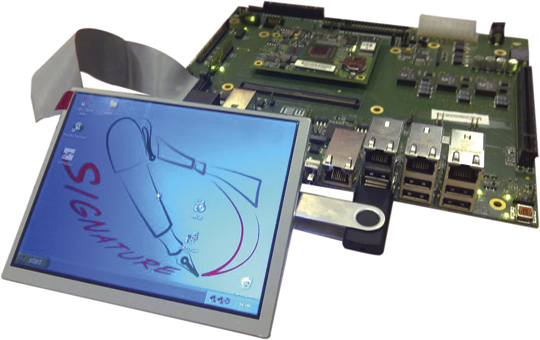
Onboard Unit. The SIGNATURE OBU (Figure 4) is based on a single-board computer (SBC) offering a high degree of flexibility. Developed by ISMB, it can host alternative receivers and positioning algorithms and manipulate different assistance data with a high degree of configurability. It is a powerful platform for developing and assessing OBU devices and their component parts, particularly as it allows lots of useful diagnostic data to be logged.
Figure 4. SIGNATURE Prototype Onboard Unit (OBU).
The OBU hosts a bespoke receiver which exploits the continuous availability of assistance data available through a high-speed data packet access connection and does not attempt to decode navigation data directly from satellite signals. This allows its design to focus on rapid signal acquisition with high sensitivity and to achieve a rapid TTFF even in areas where conventional receivers struggle. The SIGNATURE prototype has been designed using the well known SAT-SURF & SAT-SURFER platform.
The receiver, developed by the EPFL, implements massive parallelization by making use of the fast Fourier transform, leading to a processing power equivalent to approximately 650,000 equivalent correlators. The minimum sensitivity in acquisition is –145 dBm, obtained using coherent and non-coherent integrations. Thanks to the massive parallelization and the assistance, TTFF at –145 dBm is still below 3 seconds.
Positioning Algorithms. The OBU hosts positioning algorithms designed by NSL to provide high accuracy, availability, an
d integrity through exclusion of outlying measurements and provision of quality metrics (horizontal protection levels or HPLs). Numerous positioning algorithms and outlier detection strategies are being investigated. These include consistency checks applied to raw measurements and computed positions and receiver autonomous integrity monitoring (RAIM). EGNOS corrections are applied to improve accuracy and integrity indicators (user differential range error indices) are used as coarse fault-detection barrier. Consistency checks on measurements include differencing pseudoranges between epochs and checking that this rate is below a defined threshold. A RAIM algorithm is then applied to detect and exclude outliers before measurements enter the main navigation filter. Positions and velocities determined by the filter are then checked again as a further fault barrier. Checks at this stage identify if speeds are within expected ranges for the application and whether height changes are reasonable, for example.
The RAIM algorithm is based on the maximum normed residual method. For the detection procedure, the test statistic is calculated based on weighted sum of the squares of the residuals. This test statistic undergoes a globaltest (chi-square distribution), and is tested against thresholds that are computed based on the probability of false alarm (Pfa) and degrees of freedom (number of measurements minus number of unknowns). The exclusion procedure is based on an outlier detection technique also known as data-snooping, which is based on normed residuals and applied within the range domain. This technique uses measures of internal and external reliability, where the internal reliability gives estimates of how reliable the outlier detection procedure is, while the external reliability gives estimations of the influence of an outlier.
In the final step of the exclusion procedure, the maximum normed residual is tested against a critical value based on the normal inverse cumulative distribution, which in turn depends on the Pfa, and a decision is made on whether or not to exclude measurements. Having performed fault detection and fault exclusion until no further outliers are found, an HPL is calculated. This is the maximum horizontal position error that is guaranteed by the algorithm not to be exceeded, in accordance with the required probabilities of missed detection and false alarm. HPL is a function of visible satellites, expected error characteristics, and user geometry. Measurements which have been screened using the RAIM fault detection and exclusion are then processed in a Kalman filter.
Within the project, many alternative algorithms and configurations are being tested. As well as using RAIM in a snapshot mode to screen measurements entering the Kalman filter, fault detection can also take place within the innovation sequence of the filter itself. Weighting strategies that consider signal-to-noise ratios (SNR) as well as satellite elevations are also being used. This combined weighting is useful in reducing the impact of measurements affected by multipath in urban areas where simple elevation dependent models are often not applicable. The ultimate aim is to produce a robust GNSS positioning solution optimized for RUC in urban areas that balances the requirements of providing high availability with high integrity.
Test Methodology
The SIGNATURE end-to-end solution was tested in a series of field trials in the UK and Italy between April and July 2010. Trials took place in a range of operating conditions from rural areas with open skies to dense urban environments. In all trials, assistance data was provided from the service center in Nottingham, with messages tailored for the designated test area. The OBU recorded real-time position solutions as well as logging all raw measurements. Journey records can be sent back to the service center over a GPRS connection or can be downloaded back at the office. This allowed alternative solutions to be applied to the original datasets in post processing.
The position solutions were assessed through comparisons with high-accuracy GNSS reference solutions provided by additional onboard equipment and through processing with a map matcher (NSL’s Matchbox). Each journey record from a trial was compared against the known reference journey record to determine charging availability, accuracy, and integrity.
Using this approach, it is possible to assess whether improvements in the OBU position output are significant in terms of matching the vehicle location correctly to more road segments and with higher confidence. From direct comparisons between OBU positions and a high-accuracy reference solution alone, it is not possible to determine the significance of any changes in the OBU output in terms of final charging performance. Extensive trials of GNSS OBUs in London, for example, did not observe a relationship between location error (from OBUs) and performance at road segment level (map-matching) as map-matching can compensate for many errors. A strong relationship was observed between data availability and performance, though. Ultimately it is important to consider how successfully vehicle position can be related to charging objects, be they road segments, cordons or virtual toll-gates.
The objectives of the field tests were to:
Demonstrate that all elements of the end-to-end solution work as expected.
Assess the impact of assistance on TTFF.
Evaluate benefits of EGNOS data.
Investigate alternative positioning algorithms to optimize availability and integrity.
Demonstrate the feasibility of broadcast assistance using RDS.
Results
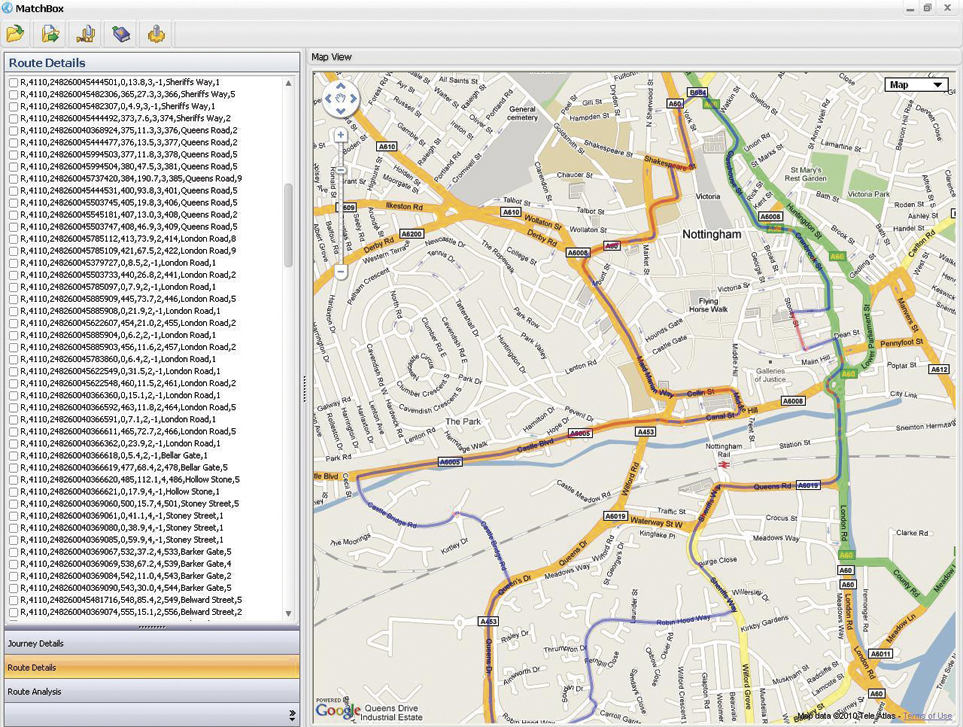
Field trials around Nottingham and Torino tested all elements of the solution. The tests confirmed the successful generation, transmission and use of assistance data, including EGNOS corrections. Position solutions determined onboard were transferred back to the service centre and processed with a map matcher. Figure 5 shows an example from a test in Nottingham city center, correctly identifying all the road segments travelled on.
Figure 5.Journey record view from Nottingham test. (Click to enlarge.)
Assess Impact of Assistance on TTFF. To examine the benefits of assistance, a series of trials were conducted to compare the TTFF of a consumer-grade receiver typically used in road applications against the performance of the SIGNATURE receiver that is assisted in all cases. They assessed TTFF for the COTS receiver in the following modes:
Hot Start: receiver has up-to-date almanac and ephemeris information so only needs to obtain timing/ranging information from each satellite to return its position fix;
Warm Start: receiver has the almanac information stored in its memory, but it does not have any ephemeris information. It also has approximate time and position knowledge. It can use this information to search for satellites but will then need to demodulate the ephemeris data from acquired signals;
Assisted: ephemeris provided over OMA-SUPL standard channel.
Table 1 shows the results from testing the receivers in open sky and urban conditions, specifically chosen to assess an extreme acquisition environment. In these tests when no valid ephemeris is available on a receiver at start-up, it takes an average of 28 seconds to determine a first position fix in open sky conditions. This increase to an average of more than 2 minutes in the worst-case urban environment as the receiver struggles to decode the navigation message on weak, noisy, and intermittent signals. With assistance, the SIGNATURE receiver maintains a rapid TTFF, outperforming the COTS receiver. The slower TTFF in the assisted COTS case may be partly due to the OMA-SUPL standard procedure
which is based on a more complex than the simple data transfer used in the SIGNATURE procedure. The COTS receiver is also decoding navigation subframes to determine signal transmission time. This can take up to 6 seconds depending on the point in the transmission cycle that acquisition begins.
Tests have also been carried out using a signal generator to control the strength of the received signal to assess acquisition and tracking sensitivity. At –145 dBm, the SIGNATURE receiver takes an average of 1.1 seconds to acquire 4 satellites and determine a first fix, and 5.1 seconds to acquire 12 satellites.
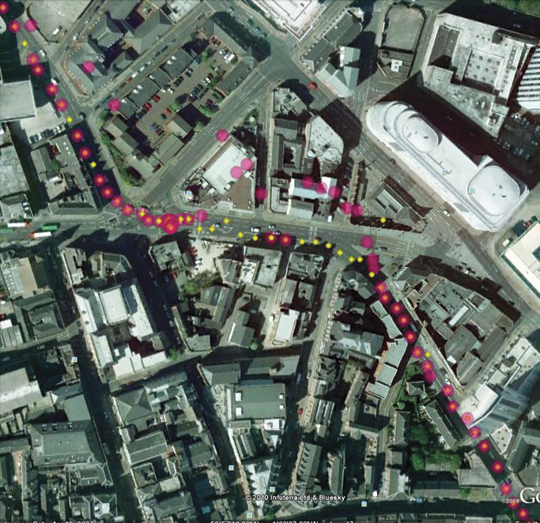
Positioning Algorithms. A variety of configurations have been investigated in the positioning algorithms, including applying outlier-detection routines at different stages of the solution and comparing snapshot and filtered approaches. Figure 6 shows a simple example of how the RAIM algorithm has been effective in detecting and excluding outlying measurements contaminated by multipath. By removing these meaurements and re-computing the OBU location, better position estimates are obtained.
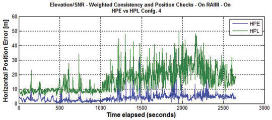
Figure 7 shows the accuracy and integrity of the SIGNATURE solution assessed using a high-grade GNSS/INS reference in Nottingham city center. In this case, the horizontal accuracy is 4.4 meters (95 percent), and the computed protection level is shown to bound the actual position error with the required confidence.
Figure 7. Position error and protection level, Nottingham city center.
In rural, semi-urban, and urban (Nottingham) conditions, a positioning solution has been demonstrated that supports all charging accuracy, integrity, and availability requirements.
Further tests were also conducted in the center of London, in a worst-case obstruction environment. In this area the current solution falls just short of the requirements defined for this project. In such cases, better performance could be obtained using a hybrid solution making use of additional sensor inputs, but this will increase equipment costs and potentially installation costs, too. A more practical approach may be to simplify charging schemes in the densest urban environments, using zones and cordons rather than using more detailed approaches that require a continuous high-performance positioning solution to be maintained in all conditions.
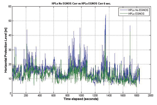
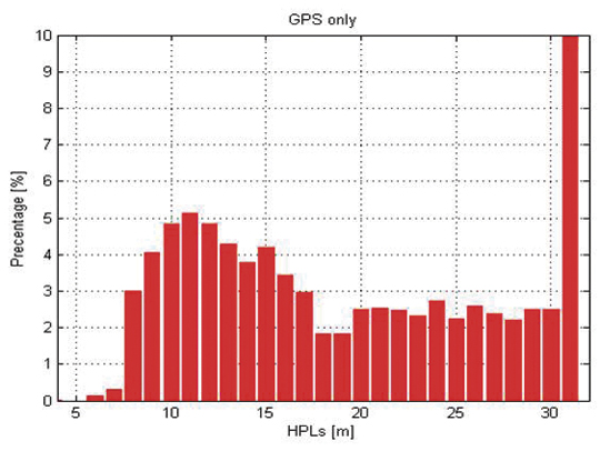
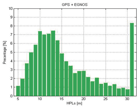
Benefits of EGNOS Data. The SIGNATURE solution has the ability to provide EGNOS data to positioning algorithms on the OBU and to vary the rate at which this information is updated and used. Field tests have assessed the potential benefits of this source of data in various environments, starting from the case in which EGNOS messages are continuously available for the positioning solution and then investigating how any beneficial effects lessen as the data is provided less frequently. The greatest benefit from EGNOS was derived by applying corrections prior to performing the RAIM FDE algorithm. This led to more consistent measurements and produced lower HPL values. Figure 8 shows a comparison for a Nottingham test in which a GPS-only solution is compared against an EGNOS solution in which a full set of corrections is provided.
Figure 8. HPL GPS vs GPS + EGNOS.
This reduction in HPL values through the application of EGNOS corrections is clearer when the distribution of HPL values falling into discrete bins is assessed (Figures 9 and 10). Similar levels of relative improvement have been found through using this approach in all test datasets. The significance of these improvements can only be judged against the detailed specifications of a particular charging scheme.
Figure 9. HPL distribution GPS.Figure 10. HPL distribution GPS + EGNOS.
Conclusions
Using an assistance service based on EDAS, it is possible to achieve a TTFF of a few seconds, which supports the high availability requirements of RUC. Field trials showed that providing EGNOS information over the assistance data link had an integrity benefit. Applying corrections prior to a RAIM algorithm leads to more consistent measurements and reduces HPLs. Robust positioning solutions have been developed and implemented on the OBU, and a test methodology has been put in place to assess the impact on charging availability, accuracy, and integrity. Results indicate that GNSS-based road charging offers the performance and flexibility to meet current and future requirements, provided availability and integrity issues are properly taken into account.
Acknowledgments
The SIGNATURE project has received funding from the European Community’s Framework Programme (FP7/2007-2013) under Grant Agreement No. 228237 and is supervised the European GNSS Supervisory Authority (GSA). Full details of the project can be found at www.gnsssignature.org. Any views expressed here are entirely those of the authors and do not necessarily represent the EC.
Manufacturers
The SIGNATURE receiver is based on the Terasic Altera DE3 System with a high-density Stratix III FPGA (EP3S260), and on the Rakon GRM8652 high-performance front end.
Kevin Sheridan is technical manager at Nottingham Scientific Limited (NSL),where he works on development of robust GNSS positioning solutions for urban applications. He has a Ph.D. from University College London.
Tomas Dyjas is a navigation engineer at NSL where he develops and tests positioning algorithms for an experimental OBU for road-user-charging (RUC) and evaluating novel integrity approaches for aviation.
Cyril Botteron manages research and project activities of the GNSS and UWB research subgroups at the Ecole Polytechnique Fédérale of Lausanne (EPFL) in Switzerland. He received a Ph.D. from the University of Calgary.
Jérôme Leclère is a Ph.D. student at EPFL. His research focus is on acquisition and high-sensitivity GNSS receivers.
Fabrizio Dominici is the head of technologies for Galileo/EGNOS applications and embedded systems at Istituto Superiore Mario Boella (ISMB). He received a master’s degree in communications engineering from Politecnico di Torino.
Gianluca Marucco received a master’s degree in electronics engineering from Politecnico di Torino. His research interests include multipath mitigation techniques for future Galileo receivers and real-time performance monitoring services for EGNOS.