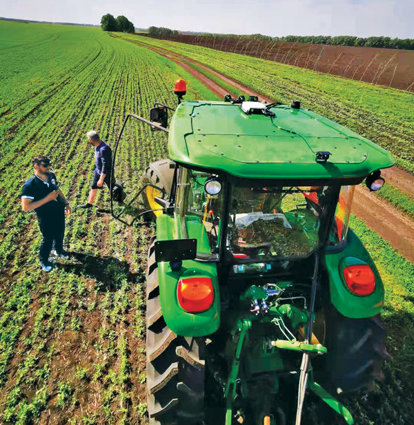
The earliest article about GPS and agriculture that I found in my collection of this magazine(*) is from the July/August 1992 issue: “Using GPS in Agricultural Remote Sensing,” by Eileen M. Perry of the Remote Sensing Research Laboratory of the USDA Agricultural Research Service. Thirty years later, you cannot buy a tractor from a major manufacturer that does not come equipped with a GNSS-based guidance system, and precision agriculture routinely makes use of remote sensing data and geographic information systems (GIS). The data are collected by Earth observation satellites, manned aircraft, UAVs and sensors on farm machinery. The GIS are used to collect, manage and analyze these data and create maps for the variable-rate machines to follow when seeding, irrigating, spraying fertilizer, herbicide and pesticides, and harvesting.
In this cover story, managers at Trimble, Tallysman Wireless, and ComNav Technology give their perspective on precision agriculture. Additionally, Gavin Schrock explains recently introduced options for tiered precise point positioning (PPP) services, using Trimble’s CenterPoint RTX as an example.
Proponents of precision agriculture and equipment vendors have always claimed that it reduces inputs (water, seeds, fertilizer and pesticide) and environmental impacts while increasing yields and profits. However, I have never been able to find any independent, reliable and comprehensive study of precision agriculture’s return on investment. If you are aware of any, please let me know, at [email protected].
— Matteo Luccio, Editor-in-Chief
Check out these perspectives on precision agriculture:
* I have the entire collection of GPS World’s print edition, except for the first issue, the 10 issues in the second year (1991), and the September through December 1993 issues. I would be thrilled to receive those missing issues, or facsimiles, from anybody who has them.
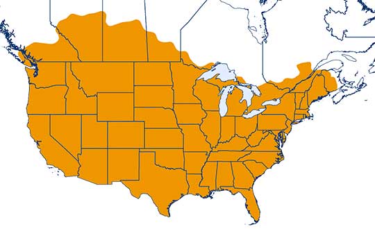
One-inch GNSS accuracy in under a minute, delivering seamless high-precision performance across the U.S. and southern Canada
Trimble has completed expanding its CenterPoint RTX Fast correction service, with coverage now spanning the contiguous U.S. and southern Canada. This expansion is central to Trimble’s vision to transform how and where users can leverage precision and accuracy.
Coverage of Centerpoint RTX Fast. (Image: Trimble)
Designed for autonomous applications in both on-road and off-road markets, the coverage and performance of the service enables industry professionals to re-think what is possible when using augmented positioning for improving safety, performance, productivity and operational efficiency.
The CenterPoint RTX Fast subscription service delivers horizontal positioning accuracy of 1 inch (2 centimeters) or less in under a minute, with the versatility of satellite or cellular delivery. This expanded coverage makes it the largest, high-performance GNSS correction network in the world, according to Trimble.
Base stations not required. The service encompasses more than 5 million square miles across North America and Europe. By using the service, said Trimble, farmers, land surveyors and GIS professionals can untether from the cost and complexities of GNSS base stations.
In addition, Trimble RTX Fast offers a single, continuous correction technology platform for enabling a broad range of safety-critical autonomous applications in markets such as automotive, agriculture and construction.
“This achievement is a major milestone in the continuous evolution of our correction service and autonomy strategy. We are delivering unmatched access to fast, reliable, highly accurate positioning in more areas than ever before,” said Patricia Boothe, senior vice president of Trimble’s Autonomy Sector. “Whether enhancing performance in the autonomy ecosystem or simplifying traditional mapping and surveying workflows, RTX Fast users can gain greater accuracy to improve productivity and operate safely — ultimately transforming the way they work and drive.”
CenterPoint RTX Fast subscriptions for Trimble RTX-compatible GNSS receivers are available through Trimble’s Authorized Business Partners or Trimble’s online store.
GNSS and inertial navigation sensors are meeting the challenges of extreme conditions, from freezing Arctic ice to the edges of steaming volcanoes, from high-speed aircraft over cities to the subways under them. Even beyond, into deep space.
IN THE ARCTIC
Wave Buoys Help Study Arctic Climate Change
Where the edge of Arctic ice transitions to open water, towering seas are smashing sea ice into melting pieces, with far-flung effects on climate and nature. Over recent decades, the Arctic has warmed more than any other region, leading to a significant reduction in sea ice volume. The combination of increased ice-free area and more mobile ice cover has led to the emergence of a seasonal marginal ice zone (MIZ) in the Beaufort Sea, north of Prudhoe Bay, Alaska.
The United States Office of Naval Research conducted a five-year study of the MIZ, which included intense field work in the freezing Arctic sea. Here, the ice is vulnerable to ocean surface waves that form in the open water, resulting from strong winds and frequent storms. Also studied were in-ice waves, where ice and water clash. The goal was to understand how both factors impact the ice floe melting.
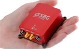
The MIZ lies in the subarctic seas in winter and transitions into the interior of the Arctic Basin in summer. To investigate the MIZ’s dynamics, ONR engaged an international program of observations and simulations using several autonomous systems, including wave buoys. The wave buoys — officially designated the autonomous ocean flux buoys — integrate SBG Systems’ miniature inertial sensors.
The MIZ study comprised an international team of scientists from more than a dozen organizations.
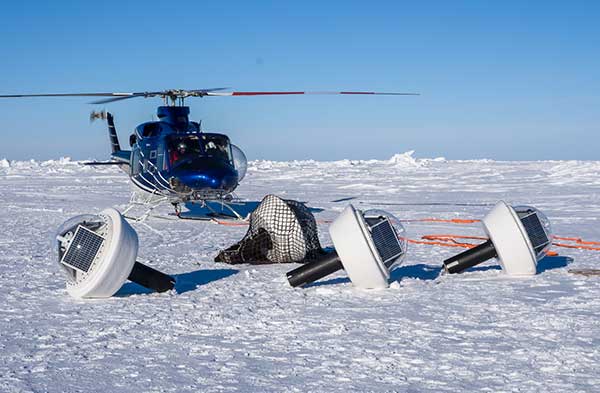
Buoys for All Seasons. The program included 20 buoys deployed in the summer, and five in the winter, to quantify open ocean and in-ice wave characteristics and evolution. “We needed a very rapid and cost-effective solution to measuring directional wave spectra in the ocean,” said Martin Doble, oceanographer at the French UPMC School and member of the research program. “Time to deployment was very short, so an integrated solution, giving us good heave numbers straight out of the box, was essential. Delivery time of the units was also critical.”
Drilled into the ice, the summer buoys were powered with solar panels and equipped with SBG Systems’ IG-500A miniature attitude and heading reference system to detect both distant and near-wave effects on the local ice floe. Once the ice melted, the summer buoys continued to measure open ocean characteristics.
Five winter buoys were installed on the ice. These buoys were made of aluminum for better resistance and contained enough battery power to keep them going through the dark winter months. Every buoy also contained processing and control electronics, an SD card, a GPS receiver and an Iridium satellite modem and antennas to transmit the recorded data to its base station. Both summer and winter data from the buoys were used to quantify the wave attenuation rate.
Winter buoy installed on an ice floe. (Photo: SBG Systems)
By measuring the waves and ice, the buoys help scientists understand how waves are approaching and breaking up the sea ice. When winter approaches and ice begins to refreeze, the buoys help show how the waves interact with the ice as the temperatures change.
Calibration. The IG-500A inertial sensors were used for wave height and direction. IG-500A measures in real time the roll, pitch, heading (accurate to 0.35°) and heave (accurate to 10 centimeters). Every sensor is calibrated for bias, linearity, gain, misalignment, cross-axis and gyro-g from –40° to +85°C. The calibration is key to enabling the sensors to provide reliable data in the harsh environment.
Doble said the units were reliable, with no failures in the harsh Arctic conditions. They ran continuously for more than a year without requiring power cycling, and “the numbers look good, giving clear results.”
The data is helping researchers understand the physics that control sea ice breakup and melt in and around the ice edge. “We have this amazing picture of the ocean, atmosphere, and ice going from the fully frozen period in March to meltdown and breakup right through to freeze-up,” said Craig Lee of the University of Washington’s Applied Physics Laboratory.
The IG-500A sensors also delivered heave measurement, important for instrumented ocean buoys. During the project, SBG Systems released the Ellipse Series, and the new line replaced the IG-500 series. More accurate in attitude and more reliable (with an IP68 rating) for the same budget, the new miniature inertial sensors now provide a heave measurement that automatically adjusts to the wave period, resulting in higher performance.
Clear differences were measured between surface wave activity outside of the ice, and then moving into the ice, with huge attenuation as the waves enter the ice and die back quickly.
Current Arctic Program. Following the close of the MIZ project in 2015, the ONR launched a new project for 2016–2020, the Stratified Ocean Dynamics in the Arctic (SODA). SODA is also taking place in the Beaufort Sea, and is using the autonomous ocean flux buoys. The buoys are now equipped with SBG’s Ellipse-A sensors.
Why the Arctic Matters
“There’s no question that the Arctic sea ice extent is decreasing,” said Martin Jeffries, program officer for the ONR Arctic and Global Prediction Program. “Multiple sources of data — autonomous underwater gliders, ice-measuring buoys and satellite images of the marginal ice zone — were used to help understand why the ice is retreating.”
The implications for the U.S. Navy, and the world, are significant. If there were no sea ice in the Arctic at the end of summer, that would mean that the Arctic Ocean would, until the winter ice came in, be completely open — something unprecedented in living memory, Jeffries noted.
Naval leaders have made it clear that understanding a changing Arctic is essential for the Navy to be prepared to respond effectively to future needs.
“[T]he opening of the Arctic Ocean has important national security implications as well as significant impacts on the U.S. Navy’s required future capabilities,” said then Chief of Naval Operations Admiral Jonathan Greenert, in his introduction to the U.S. Navy Arctic Roadmap, 2014–2030, published in 2014. “The United States has a history of maritime homeland security and homeland defense concerns in the Arctic Region […] .”
In the period between 2007 and 2014, satellites recorded the eight lowest sea ice levels ever. A key goal of the MIZ and SODA programs is to use the new data collected to make better predictive computer models — ensuring safer operations for not only naval vessels, but also anticipated increased sea traffic by shipping and fishing industries; oil, gas and mining companies; and tourism operations.
Much of the data coming in to Arctic scientists is now from improved sensors, with greater ability to survive the harsh weather and ocean conditions.
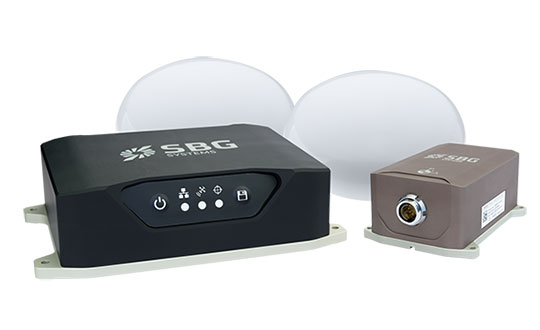
Inside the Ellipse
Alexis Guinamard, chief technology officer of SBG Systems, described to GPS World the company’s most advanced sensor for extreme environments.
“Of course we have more precise sensors like Ekinox, Apogee or even Horizon, for ‘extreme’ precision. But for extreme environments, the more appropriate sensor line is the Ellipse series,” Guinamard said. “There are several key parameters that make them better for this kind of environment.”
Those features include a high-temperature calibration range, from –40°C to +85°C, which enables the sensors to operate at the same performance level in the most extreme temperature environments.
“While typical entry-level or industrial-grade sensors only provide a room temperature or basic temperature calibration, we have developed a calibration procedure used for both survey-grade and industrial-grade sensors using a precision two-axis rotary table with temperature chamber,” Guinamard said. “An advanced thermal modeling minimizes the calibration error over the full temperature range.”
Ellipse-D dual-antenna mini INS/GNSS. (Photo: SBG Systems)
The sensors work in highly dynamic and vibrating environments because their gyros operate well, changing position up to 900° per second. Similarly, their accelerometers can reach up to 40 g, with excellent behavior in vibrating environments. “We can typically install our sensors directly on the chassis of the vehicle, while lower grade sensors may require specific dampers that are complex to design and make it difficult to precisely align the sensor,” Guinamard said.
A GNSS interference-mitigation capability enables the sensors to perform in challenging GNSS environments.
With the Ellipse-D, high latitude operation is possible because it provides a dual-antenna heading that is insensitive to higher latitudes, Guinamard explained.
Saltwater-Proof. SBG Systems sensors typically have waterproof (IP68) enclosures that can deal with harsh conditions and sustain exposure to saltwater for a limited period of time. For long exposure to salt water, the company offers specific titanium enclosures. For instance, its Navsight series has a saltwater-proof inertial measurement unit.
Navsight marine solution. (Photo: SBG Systems)
The Navsight Marine Solution is a motion and navigation solution for hydrographers available as a motion reference unit (MRU), as an inertial navigation solution (INS) with embedded GNSS, and as an INS using a third-party GNSS receiver.
Navsight can be outfitted for demanding shallow- or deep-water environments to survey highly dense areas (bridges and buildings), as well as applications where only a single antenna can be used.
With the addition of the Horizon inertial measurement unit (IMU) to the Navsight line in January, which joined the Ekinox and Apogee IMUs, the line is suitable for large hydrographic vessels surveying harsh environments. The Horizon IMU is based on a closed-loop fiber-optic gyro (FOG) technology that enables ultra-low bias and noise levels, allowing robust and consistent performance.
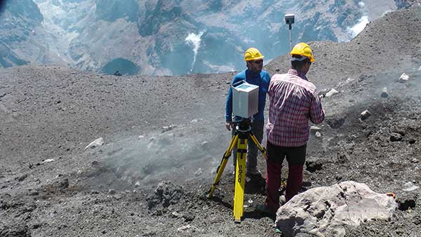
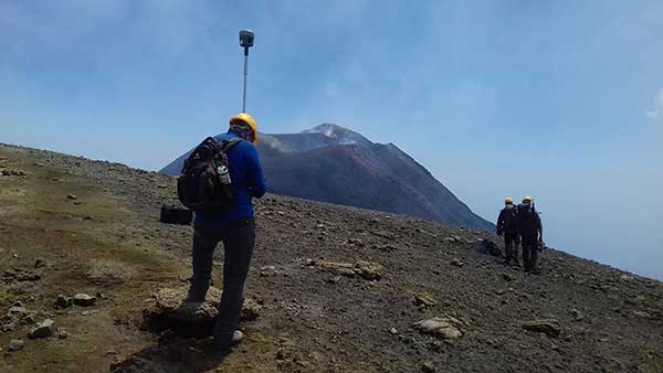
Dust, noxious gas and loose rock near the summit makes volcanic surveying especially challenging. (Photo: Trimble)
AT VOLCANO’S EDGE
GNSS Tracks Magma on Mount Etna
Scientists seeking to better understand volcanoes are using GNSS to investigate one of the most active in the world.
Mount Etna, in eastern Sicily, Italy, has been erupting for hundreds of thousands of years. The constant activity makes it a popular tourist attraction — smoke often billows from the mountain and fiery lava spews down its sides.
Researchers flock to Mount Etna, too, to study the movement of magma — the hot fluid beneath the Earth’s surface from which rocks are formed when cooled.
To measure the vertical gradients of gravity on Mount Etna’s slopes and summit craters, geophysicists from Slovakia and Italy teamed up on a field campaign during which they used high-accuracy GNSS positioning with emphasis on accurate height measurements to collect gravimetry and topographic information.
The extreme environment and spotty cellular coverage on Mount Etna made using GNSS with real-time kinematic (RTK) or virtual reference station (VRS) a challenge. The geophysicists used the Trimble CenterPoint RTX correction service and Trimble R10 GNSS receivers to ensure reliable GNSS performance.
“On many points, especially the higher part of the volcano, Internet signals were poor or [there were] none at all,” said Juraj Papčo, a geodesist with the Earth Science Institute of the Slovak Academy of Sciences. “Only by using RTX were we able to collect real-time data. It performed well in higher elevations and difficult conditions.”
The project teams also used Trimble RTX to navigate to locations where they needed measurements. At each station, they collected static and real-time positions and later compared post-processed results with the real-time positions.
Dust, noxious gas and loose rock made approaching the summit especially challenging. Trimble RTX helped the Slovak-Italian team of geophysicists better understand volcanoes and anticipate volcanic events.
Researchers used high-accuracy GNSS positioning to collect gravimetry and topographic information. (Photo: Trimble)Prisms affixed to the track enable measurement of change and structural movement. (Photo: Topcon)
UNDER A METROPOLIS
Harsh Construction Environment Monitored
Deep beneath Paris, work is underway to expand the Metro, the city’s rapid transit system. The Grand Paris Express project encompasses a 200-kilometer-long network of railway lines — mostly underground — that will link the suburbs to the city.
The contractor responsible for monitoring construction of the first stage of the project’s infrastructure, Cementys, is using more than 100 instruments from Topcon’s MS series of robotic total stations because they can withstand the harsh construction environment.
Monitoring structural movement across the network is critical; the goal is to protect the surrounding Parisian structures and the people who live and work in them. Use of the monitors also ensures that the expensive equipment used on the project is not stolen.
Topcon’s MS Series robotic total stations continuously measure the angles and distances of prisms fixed to structures. As a result, site engineers know immediately when measurement change and structural movement occurs. The technology also includes Matrix Detection software to help increase the measurement system’s speed and accuracy. The company’s TSshield integrated security software, standard on all its total stations, provides remote locking and location positioning data to within 100 meters, depending on GPS and cellular coverage.
“We have been able to integrate this open technology perfectly into our global data management system, which also includes optical fibers sensors, vibrating wire sensors, and others,” said Cementys CEO Vincent Lamour.
Construction of the Grand Paris Express project is taking places in stages and is expected to be complete in 2030.
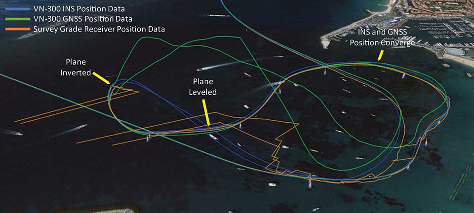
Photo:Position tracks from two laps of the race show that when the plane inverts and starts to track the reflected signal, the VN-300 GNSS/INS (blue trace) reverts to free inertial navigation and propagates the position based on inertial data. The trace follows a smooth trajectory through the next air gate until the GNSS data converges with the INS position. (Image: Google Earth with VectorNav Data)
ABOVE THE SEA
Flying High with Augmented Reality
The 2018 Red Bull Air Race World Championship in Cannes, France, made it easier for fans to follow along. Though pilots race one at a time, the new “Ghost Plane” augmented reality imagery provided fans with a real-time representation of each pilot’s flight, which challenges their speed, precision and skill maneuvering lightweight racing planes.
The Ghost Plane is driven by onboard telemetry data gathered during flight. For a pilot’s run to be accurately represented, the onboard telemetry system has to track position, velocity and attitude (yaw, pitch and roll) through high-dynamic maneuvers and in challenging environmental conditions.
While every Red Bull Air Race track layout is different, they all include a difficult vertical turning maneuver (VTM), where pilots pass through a gate and turn 180 degrees to reverse course quickly without exceeding the g limit.
Each plane is fitted with several GNSS receivers to track the plane, but dynamic maneuvers made during the race rapidly changes which satellites the GNSS receiver can track, which typically results in a loss of position fix.
To further increase the challenge for the telemetry systems, races are commonly held over water, which can reflect GNSS signals and create significant multipath errors at low altitudes. During the VTM, the plane can experience 300°/second angular rates and 12-g accelerations, during which GNSS tracking is typically lost because the antennas no longer point to the sky.
To make the Ghost Planes possible, a VectorNav VN-300 dual-antenna GNSS/INS (inertial navigation system) couples gyroscope and accelerometer data to propagate position and velocity estimates during loss of GNSS measurements through maneuvers such as the VTM.
The VN-300 combines two GNSS receivers with a 9-axis inertial measurement unit (IMU). It couples acceleration and angular rates from the IMU with position and velocity data from the receiver using a quaternion based Extended Kalman Filter (EKF). VectorNav algorithms work in conjunction with the state estimation filter, making the VN-300 more robust and intelligent, and enabling it to reject poor GNSS data and perform accurately in high-dynamic maneuvers and challenging operating conditions.
NEW EQUIPMENT
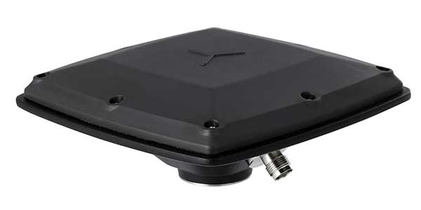
Antenna Designed for Challenging Environments
CHC Navigation’s latest GNSS antenna is an example of a product designed specifically for harsh environments.
AT311T antenna. (Photo: CHC Navigation)
The heavy-duty CHCNAV AT311T is designed for demanding applications subject to shocks and vibrations. With advanced filtering and robust signal tracking, it provides survey-grade GNSS signals to enhance position reliability for marine applications, machine control, precision agriculture and industrial automation.
Features include multi-constellation GNSS tracking using GPS, GLONASS, BeiDou, Galileo, QZSS, IRNSS and SBAS. Its IP68 water-resistant design makes it safe to use in extreme conditions with a wide temperature range (–40°C to +85°C). Its internal stacked structure enhances performance in high-interference environments, and the 40-dB signal gains, advanced signal filtering and multipath rejection design provide superior and robust GNSS signal tracking in challenging surroundings.
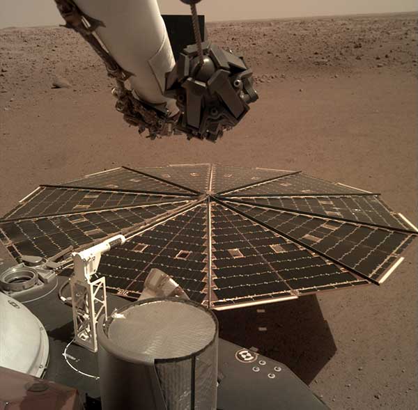
One of the two solar arrays on the InSight lander dominates this view of the plain of Elysium Planum, taken Dec. 4, 2018. (Image: NASA/JPL-Caltech)
IN OUTER SPACE
Exploring Beyond Earth
While GNSS isn’t useful on the surface of Mars, inertial navigation is a key technology for exploration of the red planet. For instance, the Northrop Grumman LN-200S sensor guided the Mars Opportunity rover, which explored Mars for 15 years until a storm struck in June 2018.
The LN 200S sensed acceleration and angular motion, with its data output used by the rover’s control systems for guidance.
The hermetically sealed unit, suitable for planetary and asteroid probes, helped position the rover’s antennae to relay photos and data to satellites. Opportunity beamed back 187,000 raw images, according to NASA.
Because IMUs don’t depend on satellites, they work well for deep space missions, Honeywell explained in a press release.
In November 2018, NASA’s InSight spacecraft landed on Mars to study the interior with a heat probe and listen for marsquakes with a seismometer. Aboard was Honeywell’s Miniature Inertial Measurement Unit (MIMU), an IMU that has been a part of Lockheed Martin’s Mars satellites and landers since 1998.
The MIMU is a three-axis strapdown device specifically designed for the satellite and deep-space-probe market (more than 500 MIMUs have been deployed throughout the solar system). It uses ring laser gyros to help control and stabilize a spacecraft during entry, descent and landing, as well as maintain orbit and payload orientation. The radiation-hardened design supports 15-year missions.
The Trimble CenterPoint RTX correction service, enabling centimeter-level absolute positioning around the world without the need for RTK reference-station infrastructure, is now available to many users, including integrators of professional high-precision equipment and consumer products such as in the automotive sector. Access is provided via a software library compatible with any GNSS device. The corrections now contain detailed integrity information for safety-critical applications.
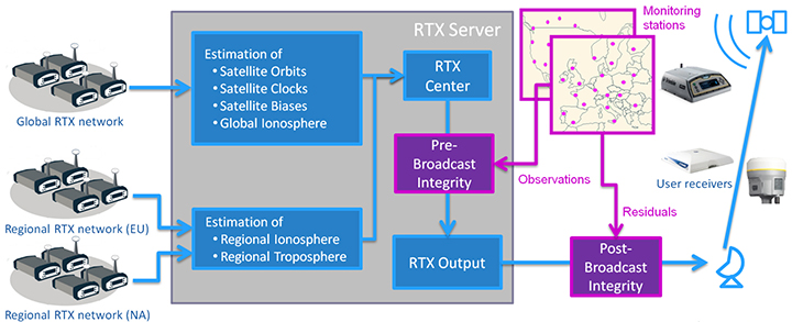
The RTX infrastructure is made up of approximately 120 globally distributed RTX reference stations. Receivers at these stations transmit measurement data at 1 Hz to the RTX server centers, where the correction data is computed. For redundancy purposes, multiple servers in the United States and Europe are operated. A failsafe architecture avoiding any single point of failure in the processing chain has produced a very high availability of corrections. Today the system supports GPS, GLONASS, Galileo, BeiDou and QZSS satellites. It is a multi-frequency system supporting two or more frequencies for each satellite system.
The correction stream is available to users using L-band signals broadcast via geostationary satellites and IP connections. The L-band transmitted RTX data stream uses a bandwidth of 600–2400 baud, and a highly compressed data format with a resolution of 1 millimeter, with an average latency of 8 seconds in L-band mode and 5 seconds in IP mode. The data stream is encrypted via an Advanced Encryption Standard (AES) with a key length of 256 bits to guarantee safe transmission. Data transmission integrity is assured with a 32-bit cyclic redundancy check attached to every message. The RTX correction stream provides information on satellite position, satellite clock, ionospheric and tropospheric models, and code and phase biases.
The orbit determination is done in real time using a reduced dynamic approach with dynamic models and exploiting the accuracy of the phase measurements after ambiguity fixing. Based on the computed orbits, the satellite clocks are estimated at 1 Hz, where integer ambiguity fixing is performed for the different satellite systems.
Next, a single-layer global ionospheric model is computed and represented through spherical harmonics. There are currently two areas with a denser network than the global network; these cover Europe and the mainland U.S. with more than 1,000 base stations. Using these stations, regional ionospheric and tropospheric models are computed, which then provide a fast convergence (RTX-Fast service).
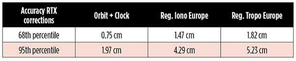
The satellite position and clock information has centimeter accuracy and allows the client to compute precise point positioning (PPP) with carrier-phase ambiguity resolution. Table 1 shows service accuracy.
Table 1. Accuracy of the RTX corrections from more than three years (June 2015–July 2018) of residuals computation in the European RTX-Fast network. (Table data: authors)
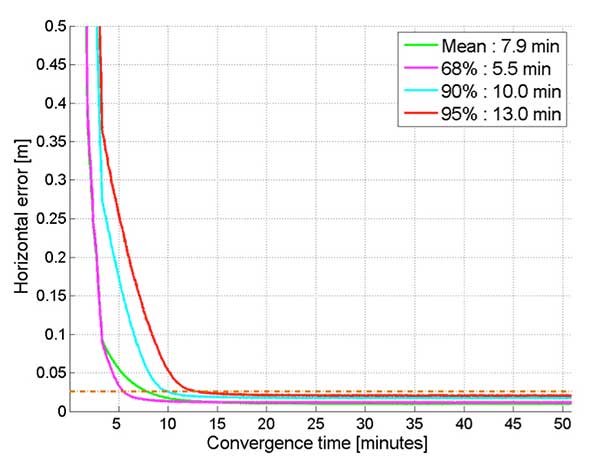
Once the ambiguities are resolved, the position solution is accurate to a few centimeters. The global RTX-Standard service provides convergence times of 7 minutes to 20 centimeters (cm) horizontal error (95%) and to 2.5 cm (95%) in 13 minutes as shown in Figure 2. The regional RTX-Fast service (U.S., Europe) provides convergence times of less than a minute with centimeter accuracy. The warmstart convergence time is approximately 13 seconds.
Figure 2. Global convergence of RTX out of 52 globally distributed stations covering one month of data. (Image: Trimble)
The accuracies specified are achievable with precise Trimble GNSS positioning hardware. For integration into non-Trimble devices, an RTX software library is offered, which gives the user real-time access to the individual data in the RTX correction stream. For use of this library in safety-critical systems such as advanced driving-assisted systems (ADAS) or semi-automated driving, this library was certified to follow the ASIL-B ISO 26262 standard and the automotive ASPICE standard. This library is available for easy integration into third-party applications.
In addition to the real-time RTX solution, a web-based post-processing solution is available for public use free of charge. It is possible to upload static Trimble or RINEX files to the server, post-process the measurement data, and retrieve a precise position in various coordinate frames.
Service integrity is continuously monitored at independent stations from the RTX tracking networks in Europe and the US. The integrity of the service is provided at the correction data domain. The integrity monitoring part of the RTX system minimizes the risk due to events such as unplanned satellite maneuvers or wrong broadcast ephemeris; satellite signal or clock anomalies; ionospheric storms; or problems in transmitting the RTX correction stream.
The monitoring stations compute phase observation residuals (with ambiguity fixing) using the station measurements and the received RTX corrections. These residuals represent the actual errors of the corrections as seen by the monitoring stations at the line-of-sight (Table 1). The thresholds at which corrections are considered as faulty are the following: 0.5 m + QI (quality indicator) for orbit + clock corrections and regional tropospheric models, and 1.0 m + QI for regional ionospheric models.
The integrity monitoring consists of two steps (Figure 1): a pre-broadcast check, where potentially faulty corrections are detected and filtered out before leaving the computing server, and a post-broadcast check, where additional errors in the transmission channel are detected and alarms are issued to the users.
Figure 1. Generation and transmission of RTX global and regional corrections, including pre- and post-broadcast integrity monitoring. (Image: Trimble)
Integrity flags and alarms are constantly inserted into the correction stream and output by the RTX client library. The integrity information notifies clients of the presence of integrity monitoring and provides timely alerts in case of detected correction-data integrity violations. The time-to-alert limit goals are 17 seconds for L-band transmission and 13 seconds for IP transmission for the RTX service.
The RTX corrections includes quality indicators. In particular, the quality indicator for the satellite clock includes a “DoNotUse” flag to indicate potential problems with the given satellite. This flag prevents the use of the satellite for positioning when received by the user. The quality indicators of the corrections are indeed a first integrity layer. In 2017 the pre-broadcast integrity monitoring was added to act as a second layer. In 2019, with the addition of the post-broadcast integrity monitoring, a third integrity layer was added to the RTX correction data stream.
The RTX system provides access to centimeter-level corrections allowing centimeter positioning on a global basis. RTX-Fast services are available in Europe and the U.S. with pre- and post-broadcast integrity monitoring currently being deployed.
The authors are engineers with Trimble Terrasat GmbH, Germany.
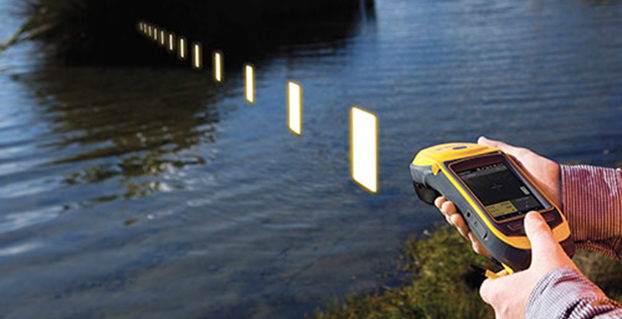
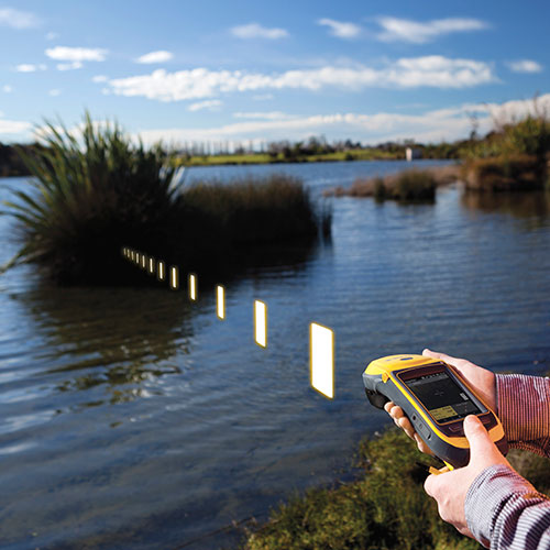
A video featuring a South African veteran surveyor, telling his story of achieving 2 cm horizontal accuracy with Trimble CenterPoint RTX. Satellite-delivered, survey grade accuracy and no base station required!
The 2014 Trimble Dimensions User Conference is being held in Las Vegas this week. Photo: Trimble
With more than 4,000 attendees, this year’s Trimble Dimensions User Conference was the largest ever and, I must say, a well-organized event chock full of technical content — enough to squelch the most intense geospatial hunger pangs you might have.
One could write a book on all the technology and market segments that Trimble is pursuing and offering solutions for. In addition to a wide range of GNSS, geospatial, construction, control, and data management systems previously offered, Trimble boasted a USB stick full of press releases with new product and service announced at Dimensions. So, the challenge is deciding what to write about without writing a little bit about everything.
After my first day at Dimensions, it became clear to me what I needed to do. Among the many product and service announcements was a new GNSS correction service named Viewpoint RTX. While I’ve tried to stay up to speed on Trimble’s various GNSS real-time correction services, this one was the straw that broke the camel’s back for me. I decided I needed to get a solid grip on the range of real-time GNSS correction services that Trimble offers because the picture was getting fuzzier, at least to me, with each new real-time correction service introduced. It used to be pretty simple to decipher; not so much any longer. So I had a conversation with Patty Boothe, general manager of Positioning Services at Trimble. Patty, a 15-year Trimble veteran, was appointed GM of the newly formed group three years ago. Here’s the low-down on the services.
Remember, Trimble acquired the land portion of OmniSTAR’s business a few years ago. For years, OmniSTAR has been one of the two dominant commercial satellite-based, real-time GNSS correction services (the other being John Deere’s Starfire service, as well as new entrant Terrastar). The OmniSTAR acquisition was Trimble’s entry into the satellite-based, real-time GNSS correction services business. Since then, Trimble has introduced the RTX (not to be confused with RTK) range of GNSS correction services. You might say that OmniSTAR and RTX are competitive services within Trimble. They are, to a certain extent, and I’ll attempt to clarify that below.
Following is a list of Trimble’s real-time GNSS correction services, starting with the OmniSTAR services:
OmniSTAR VBS: Satellite-based, real-time submeter service. The VBS service has been made obsolete largely by free public satellite-based augmentation systems (SBAS) such as WAAS/EGNOS/MSAS/GAGAN/SDCM. It is still used in geographic regions where free public SBAS don’t exist, primarily South America, Central and Southern Africa, and Australia. GPS-only service. Requires single-frequency receiver (L1).
OmniSTAR XP: Satellite-based, real-time 15-cm service based on Jet Propulsion Lab (JPL) technology and delivered to users on the ground via OmniSTAR’s geosynchronous satellite network. GPS-only service. Requires dual frequency (L1 and L2).
OmniSTAR HP: Satellite-based, real-time 10-cm service based on OmniSTAR’s reference station network and delivered to users on the ground via OmniSTAR’s geosynchronous satellite network. GPS-only service. Requires dual frequency (L1 and L2).
OmniSTAR G2: Satellite-based, real-time 10-cm service based on Jet Propulsion Lab (JPL) technology and delivered to users on the ground via OmniSTAR’s geosynchronous satellite network. GPS+GLONASS service. Requires dual frequency, dual constellation (L1 and L2).
To use OmniSTAR services, one must have an OmniSTAR-enabled GNSS receiver. There are a several receiver manufacturers that support OmniSTAR GNSS correction services, such as NovAtel and Hemisphere GNSS, in addition to Trimble.
After, or at nearly the same time, Trimble acquired OmniSTAR, the company launched its RTX GNSS correction service. RTX’s infrastructure consists of ~110 GNSS reference stations around the world working to create high-precision corrections on a near global scale. The first significant differentiator is that Trimble RTX services are only offered on Trimble GNSS receivers, so you’ve got to be “all in” with Trimble to utilize RTX.
Viewpoint RTX: Internet-based (notice I didn’t write satellite-based), real-time submeter service. This is a new service introduced this week at Dimensions for the new Leap GNSS receiver and the Geo7 GNSS handheld. GPS+GLONASS service. Requires single-frequency receiver (L1).
The above are the three RTX services. There are some options for the above, but let’s talk about satellite-based GNSS correction services for a minute.
The advantage of satellite correction services is that, because GNSS corrections are delivered via satellite, your receiver doesn’t need to be connected to the Internet or have any other sort of terrestrial radio communications to receive data from the GNSS reference station(s). Because delivery is by satellite, you could be in the middle of a desert with no mobile phone coverage within 100 km, and you could still use OmniSTAR or RTX services. The only requirement is that your receiver needs to have direct, continuous line-of-sight to the OmniSTAR/RTX geosynchronous satellite (both services use the same geosynchronous satellites to broadcast the corrections).
The primary disadvantage of OmniStar and RTX services is the “convergence” time required to achieve the stated accuracy service levels. With the exception of OmniSTAR VBS (sub-meter), Viewpoint RTX (sub-meter) and Rangepoint RTX (50-cm) services, the OmniSTAR and RTX centimeter and decimeter services require tens of minutes of initialization time to converge to the stated accuracy. For example, if you want to use the 4-cm Centerpoint RTX service, you may have wait up to 30 minutes for it to converge to 4-cm accuracy.
Now, there are a couple of ways to reduce the convergence time:
Start on a known point. For example, if you’re using Centerpoint RTX on a tractor for planting and you shut down for the evening, you can start it up the next morning (assuming you didn’t move the tractor), and it will converge nearly immediately.
Trimble offers a fast convergence option ($) in some geographic areas where it augments RTX with local RTK reference stations. Currently, Trimble offers this service in five U.S. “corn belt” states.
For OmniStar XP, HP and G2 services, the only way to reduce convergence time is number one above, start on a known point.
It’s important to note that all of the centimeter and decimenter satellite-based services described above are based on real-time Precise Point Positioning (PPP) technology, which is different than RTK technology. The fundamental difference is that real-time PPP technology relies on a global, distributed network of reference stations. For example, Trimble has ~110 reference stations to cover the globe (mostly) with its RTX service. On the other hand, RTK requires a much more dense network of GNSS reference stations. For example, in Washington State there are ~100 GNSS reference stations that comprise the state-wide RTK network.
Lastly, Trimble offers a hybird RTK/RTX service called XFill. The idea is that for RTK users who lose communications to their RTK base or RTK network can use the Centerpoint RTX as a “seamless” back-up, maintaining RTK-level accuracy (1-2cm) for the first five minutes of RTX service, and then degrading to Centerpoint RTX accuracy after 20 minutes. Trimble reports there is no convergence time when transitioning from RTK to RTX, like you would if you were starting RTX right away. Standard XFill is included with certain Trimble RTK receivers and allows up to five minutes of RTX satellite time. Last month at the INTERGEO conference, Trimble introduced Expanded XFill which is a subscription service for those users who want more than five minutes of RTX time. For those users, Patty said that users can buy blocks of RTX time starting at 10 hours.
So, you might ask how Trimble handles the horizontal datum differences between RTK and RTX since they are likely not referenced to the same horizontal datum. For example, in the US, Trimble VRS RTK infrastructure is typically referenced to NAD83/2011 while Trimble RTX is referenced to ITRF08. There’s about 1 meter difference between the two. After finding the correct Trimble person, he said that Trimble does a 3-parameter local shift (dX, dY, dZ) on the fly when in RTK mode so that when there’s a transition from RTK to RTX, the horizontal datum difference is already resolved.
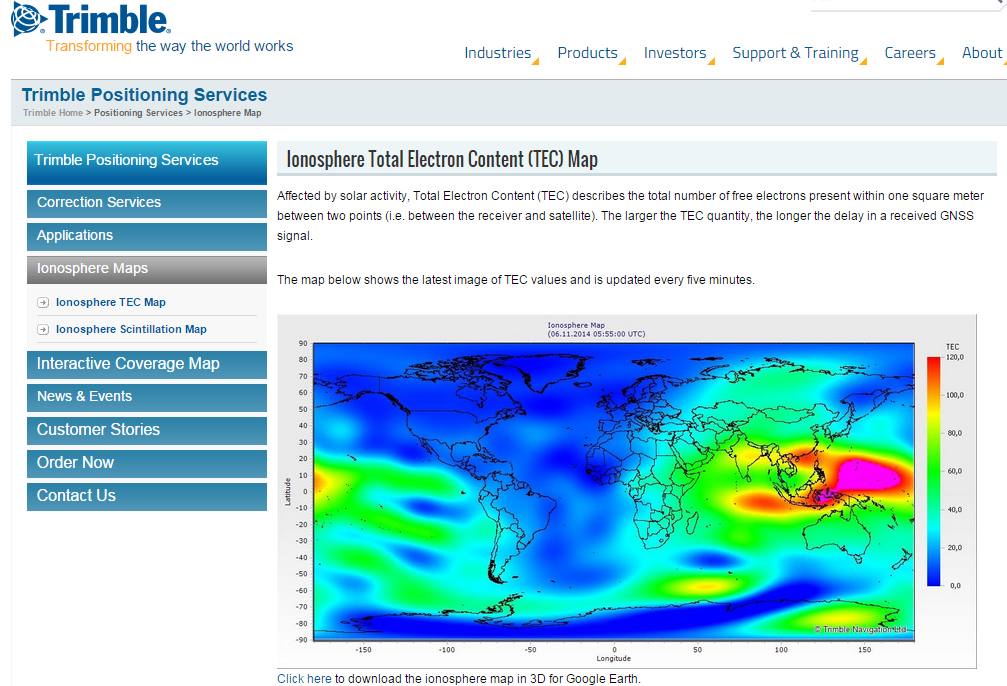
A by-product of Trimble’s ~110 global GNSS reference station network is a real-time, world-wide TEC (Total Electron Content) map. Since real-time PPP GNSS correction services (and public SBAS like WAAS/EGNOS/MSAS/GAGAN) rely on accurate models of the TEC in the ionosphere to account for the GNSS measurement delay, real-time TEC maps give users an indication of how the ionosphere’s TEC is behaving. This sort of map is particularly useful in attempting to predict the understand single frequency receivers using services such as public SBAS, OmniStar VBS, and Viewpoint RTX. The next time you here about an impending solar storm, take a look a the map using this link and see the TEC hotspots around the globe. Notice the more intense activity near the geomagnetic equator.
TEC map from Trimble’s ~110 global GNSS receivers. Photo: Trimble
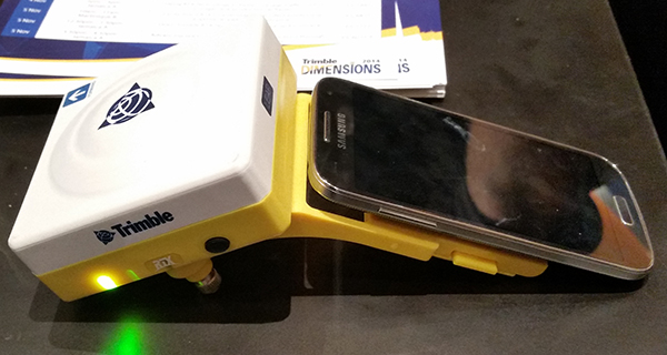
Shifting gears slightly, at the conference, Trimble also introduced a new mobile phone GNSS add-in product called Leap, which uses the Viewpoint RTX service.
Trimble Leap GNSS Receiver with a Samsung Galaxy Phone. Photo: Trimble
The Trimble Geo 7 series of rugged, high-accuracy GNSS handhelds will have RTX correction. Photo: Trimble
Trimble’s RTX technology-based correction services — Trimble CenterPoint RTX, Trimble RangePoint RTX, and the new Trimble ViewPoint RTX — will be available for Trimble Geo 7X handhelds. Trimble made the announcement at Trimble Dimensions.
Trimble RTX technology provides compatible GNSS receivers with correction services that significantly improve accuracy and reliability in obtaining positions worldwide. Geospatial professionals now have more flexibility to achieve the accuracy required by their highly mobile workflows in real-time, without being tied to a base station or local VRS network, Trimble said.
Available worldwide through an IP connection where cellular communication is available, Trimble RTX offers geospatial professionals flexibility in where and when they are able to work. Operational efficiency and productivity in the field is improved by delivering real-time DGNSS corrections directly to the Trimble Geo 7X handheld. Field challenges, such as obstructed satellites and inaccessible locations, are also minimized with Trimble Floodlight and Trimble Flightwave technology options for the Trimble Geo 7X.
The handheld solution is designed for a variety of industries — such as utility companies, municipalities, and environmental management agencies — in which workers are highly mobile and require a reliable, flexible data-collection and asset management solution.
“We have eliminated the complexities of managing multiple correction sources across a large geographically dispersed project or organization,” said Alain Samaha, business area director of GIS and Software for Trimble’s Geospatial Division. “By offering RTX-based correction services, we simplify their work and deliver the accuracy that our customers require.”
A choice of RTX correction services ranging from 4 centimeters to submeter-level horizontal accuracies is available. Customers can choose the appropriate Geo 7X handheld configuration with the RTX-based correction service that meets the accuracy level and capability required for their job.
Trimble’s CenterPoint RTX correction service is now available for heavy civil construction applications. Available worldwide as a subscription service, CenterPoint RTX offers construction companies a flexible and easy-to-deploy option for conducting pre-bid reconnaissance and initial site measurements without using a traditional base station, the company said.
“Offering CenterPoint RTX for heavy construction applications further extends the Trimble Connected Site strategy to simplify site operations. CenterPoint RTX will make it easier to collect high-quality data in the early phases of site establishment, improving material estimates and job bids,” said Roz Buick, vice president and general manager of Trimble’s Heavy Civil Construction Division. “With more accurate material estimates and bids, contractors can incur fewer change orders and avoid unnecessary costs and delays.”
Based on Trimble RTX technology, CenterPoint RTX is a satellite-delivered positioning source that streams GNSS corrections to rover systems with the Trimble SPS985 GNSS Smart Antenna, SPS985L GNSS Smart Antenna, or SPS855 GNSS Modular Receiver. There is no need to have an additional data plan or additional hardware.
The CenterPoint RTX service is a correction source for construction sites in the pre-bid and site planning phases. Construction surveyors and estimating teams can use CenterPoint RTX to perform topographic surveys, estimate quantities, and conduct site planning quickly and easily, before a base station is needed on site for machine control and other high-accuracy applications.
“Trimble strives to provide advanced GNSS correction services that fit our customer’s specific needs and applications,” said Patricia Boothe, general manager of Trimble’s Positioning Services Division. “For the heavy civil construction industry, this means a job crew can arrive on a new construction site and begin conducting site measurements and collecting data right away. CenterPoint RTX also makes it easier to work on multiple construction sites with the same rover system. There is no need to pair the rover with an existing base station at each individual site.”
Trimble CenterPoint RTX is a subscription service available through Trimble Positioning Services in North America, South America, most of Europe, Russia and the Commonwealth of Independent States (CIS), Africa, Asia, and Australasia.
Applanix, a mobile mapping and positioning company, is making the Trimble CenterPoint RTX correction service available across its entire airborne mapping portfolio. Applanix is a Trimble Company.
Using the Trimble CenterPoint RTX correction service, Applanix will be able to deliver these benefits to the aerial survey marketplace:
High accuracy — better than 10 cm RMS horizontal after convergence
Speed and low cost — no need for setting up base stations, no need to wait for delivery of public-domain ephemeris data
Simplicity — deal directly with Trimble (no third-party involvement)
More uptime and reliability — use Trimble’s professionally managed, highly maintained private network
Ease of use — there is no additional hardware to purchase, integrate or maintain
Fast and reliable convergence — 30 minutes or less to full accuracy
The announcement was made at Trimble’s China Dimensions User Conference. The CenterPoint RTX service for Applanix airborne mapping products is expected to be available in the fourth quarter of 2013.
“The Applanix aerial mapping portfolio is trusted throughout the aerial mapping community to provide highly accurate position and orientation information for directly georeferencing camera and sensor data,” said Joe Hutton, Director of Airborne Products at Applanix. “By integrating the Trimble CenterPoint RTX correction service, we are maintaining our position at the forefront of accuracy, robustness, and high efficiency in airborne mapping. The CenterPoint RTX correction service gives Applanix products the ability to achieve accuracy required for many types of mapping projects in real time and post-mission, all without the need for base stations – an industry first.”
Trimble CenterPoint RTX correction service is a GPS, GLONASS and QZSS enabled correction service built on Trimble RTX technology. It provides high-accuracy GNSS positioning without the use of traditional reference station-based differential RTK infrastructure.
The solution is also compatible with the Applanix POSPac software to achieve the same level of orientation accuracy as when using base stations, all without the need to have an Internet connection or wait for precise ephemeris data to be available.
Trimble announced today that its Trimble CenterPoint RTX correction service will be available to survey and land administration professionals around the world. Powered by Trimble RTX technology, the GPS, GLONASS and QZSS enabled correction service can offer better than 4 centimeter (1.5 inch) repeatable horizontal accuracy, without requiring the use of a base station or local VRS network.
The announcement was made today at Intergeo 2013, being held this week in Essen, Germany.
In addition to previously announced Agriculture devices, the CenterPoint RTX correction service is now compatible with the Trimble ProXRT for Land Administration and the Trimble R10 GNSS receivers. The worldwide subscription service is expected to be available to geospatial users in the fourth quarter of 2013.
Delivered via L-band satellite, CenterPoint RTX is designed for geospatial professionals who are not using RTK as the primary correction source. Advantageous in remote areas that lack local infrastructure and/or cellular coverage, the corrections are delivered directly to the GNSS receiver. No additional hardware, including radios, antennas, or even cellular data plans, is required to use the correction service.
“By combining global coverage, fast initialization times, and high-accuracy correction data, Trimble CenterPoint RTX offers geospatial professionals unprecedented operating freedom,” said Patricia Boothe, general manager of Trimble’s Positioning Services Division. “We are committed to offering field-proven positioning corrections to address a variety of users’ needs across applications and markets, starting with agriculture and now reaching into the geospatial markets.”