Ottonomy.io partners with Posten Norge for first-mile supply chain automation with autonomous robots
One of Europe’s largest postal services, Posten Norge, is testing the future of logistics delivery with Ottobots in Oslo.
Ottobot maker Ottonomy.io is collaborating with Posten Norge AS and Holo on trials for automating first-mile delivery in an effort to pave the way for autonomous delivery. See the project page.
The Posten Group is a post and logistics group that develops and provides post, communications and logistics services in Norway and the Nordic region. Holo is an implementer, integrator and operator of autonomous vehicles in the region.
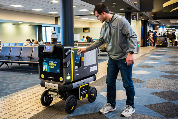
An Ottobot delivers product orders to airport travelers. (Photo: Ottonomy)
The partnership with one of Europe’s largest logistics companies is oriented towards testing how autonomous robots can improve intra-logistics, especially in city centers. Posten Norge will be leveraging Ottobots for first-mile pick-ups, receiving and delivering goods for AMOI, a Nordic digital marketplace, from the busy Aker Brygge metropolitan area in Oslo.
“Autonomous robots have previously been tested by other companies with the focus entirely on final delivery to the customer,” said Sven Richard Tønnessen from Posten’s Department of Emerging Technology. “We want to evaluate how robots can become part of Posten’s future logistics solutions.
“This project, which utilizes both humans and robots, offers many new opportunities for increasing efficiency and productivity for our organization,” Tønnessen said. “We will continue to utilize our existing pool of human couriers for delivering goods to the customers, while the robot takes care of the intra-logistics part of the supply chain.”
Conquering the First Mile
The first mile has been a pain point for organizations in metropolitan areas. First-mile delivery involves moving products from the manufacturer’s or retailer’s warehouse to a central holding center. From this location, a carrier, shipping company or logistics partner picks up the products and takes it to the next leg in the destination.
“The logistics with delivery vans at Aker Brygge is extremely demanding in terms of parking and time consuming,” said Kenneth Tjønndal Pettersen, Posten Norge. “Together with our partners, we want to test the various applications for autonomous technology, which can enable simpler logistics and reduced noise in the cityscape.”
A recipient of the 2021 Sustainability Product of the Year award by Business Intelligent Awards, Ottobot will be used to determine how Posten Norge AS can increase sustainability and efficiency for the logistics supply chain in the future.
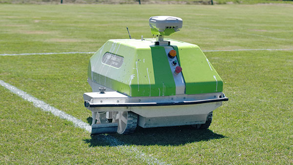
Turf Tank is an autonomous, GNSS-guided line-marking robot built specifically to paint lines on athletic fields.
More than 550 Turf Tank robots are deployed across the United States, painting athletic fields at public schools, major colleges and universities, amateur and professional soccer clubs, local parks and recreation departments, and a two National Football League stadiums.
The Turf Tank robots can paint a full soccer field in less than 30 minutes, compared to two or three hours for manual painting. Similarly, the robot can paint a football field in two or three hours compared to eight to 10 hours to paint a football field.
The robots are eco-friendly — they’re powered by rechargeable batteries and use far less paint than most older paint machines.
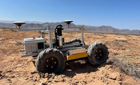
The CivDot UGV marks thousands of coordinates per day precisely and efficiently
Trimble Ventures, Trimble’s corporate venture capital fund, is investing in Civ Robotics, a San Francisco-based construction tech startup focusing on transforming surveying layout for civil engineering and infrastructure projects.
The investment supports Trimble Ventures’ mission to invest in early and growth-stage companies that are accelerating innovation, digital transformation and sustainability in the industries Trimble serves: agriculture, construction, geospatial and transportation. The investment terms were not disclosed.
The construction industry faces a variety of challenges including shortage of skilled workers, safety and productivity. Civ Robotics addresses these challenges with CivDot, a new autonomous surveying solution that empowers efficiency, productivity and safety on the job.
CivDot is an unmanned ground vehicle (UGV) designed for civil engineering and infrastructure projects such as solar farms, roadways, data centers, power plants and more. Augmenting the surveyor’s work, CivDot marks thousands of coordinates per day precisely and efficiently, while delivering layouts faster than traditional methods.
“We are focused on investing in companies that are seeking to address important challenges in markets that align with Trimble’s mission of transforming the way the world works,” said Aviad Almagor, vice president of technology innovation at Trimble and technology advisor for Trimble Ventures. “Civ Robotics technology supports surveyors and field workers and helps remove the burden of repetitive and risky work.”
Civ Robotics uses Trimble’s high-precision GNSS positioning technology and surveying software to improve productivity and increase safety, Almagor said. “This is an exciting opportunity to help accelerate innovation in autonomy, surveying and construction.”
“Trimble and our vision are in lockstep towards construction automation with a sharp focus on the highest standards of safety and quality,” said Tom Yeshurun, co-founder and CEO, Civ Robotics, which announced its $5 million seed funding round this morning. “Through Trimble’s latest GNSS technology in our autonomous surveying products, our customers can benefit from an end-to-end workflow.”
Civ Robotics will be showcased at the Trimble Dimensions+ User Conference, taking place Nov. 7-9 in Las Vegas.
The CivDot UGV, equipped with Trimble high-precision GNSS. (Photo: Civ Robotics)
With more than 80 percent of the world’s oceans unmapped, the deep ocean is one of the last unknown areas on Earth. On May 31, teams with unique exploration solutions were honored with the Shell Ocean Discovery XPRIZE.
XPRIZE is a global competition to advance ocean technologies for rapid, unmanned and high-resolution ocean exploration and discovery. The teams invented new technologies for rapid, unmanned and high-resolution ocean exploration and discovery.
The results were revealed at an awards ceremony hosted at the Oceanographic Museum of Monaco, part of the Oceanographic Institute, Prince Albert I of Monaco Foundation.
The grand prize winner, receiving a total of $4 million, was GEBCO-NF Alumni, an international team based in the United States, while KUROSHIO, from Japan, claimed $1 million as the runner-up.
GEBCO-NF Alumni was led by Rochelle Wigley, Ph.D., and Yulia Zarayskaya, Ph.D. The 14-nation team integrated existing technologies and ocean-mapping experience with a robust and low-cost unmanned surface vessel, the SeaKIT, along with a novel cloud-based data processing system that allows for rapid seabed visualization, to contribute towards comprehensive mapping of the ocean floor by 2030.
Runner-up was KUROSHIO, from Yokosuka, Japan, led by Takeshi Nakatani, Ph.D. The team integrated technologies from their partners to create a surface vessel and software platform that can operate with different autonomous underwater vessels, which increases the versatility of their technology.
Field Testing. To determine winners, the panel of independent judges reviewed data from field testing conducted in Kalamata, Greece, and Ponce, Puerto Rico. In Kalamata, teams had up to 24 hours to map at least 250 square kilometers of the ocean seafloor at five meters horizontal resolution or higher.
The gold-standard high-resolution baseline maps, against which the team maps were judged, were provided by Ocean Infinity and Fugro, while Esri, the global leader in geographic information system (GIS) software and geodatabase management, donated its ArcGIS Online platform for the teams and judges to use.
NOAA Prize. The $1 million National Oceanic and Atmospheric Administration (NOAA) Bonus Prize went to teams for developing technology that could detect a chemical or biological signal underwater and autonomously track it to its source. The award was split between junior high school team Ocean Quest from San Jose, California, which claimed $800,000 as the winner, and Tampa Deep Sea Xplorers, from Florida, taking $200,000 as runner-up.
Additionally, the judges unanimously recommended a $200,000 Moonshot Award for Team Tao from the United Kingdom for its unique approach to seafloor mapping, even though they did not meet the criteria of the competition.
As part of the total $7 million prize purse, four teams opted to compete for the $1 million NOAA Bonus Prize. In a field test in Ponce, Puerto Rico, teams needed to demonstrate that their technology can “sniff out” a specified object in the ocean by first detecting and then tracing a biological or chemical signal to its source.
The judges determined that no single team was able to trace the signal to its source in the timeframe allowed, so the prize was divided among the two teams that came the closest. In 2018, nine finalist teams were awarded an equal share of the first $1 million of the $7 million prize purse, in recognition of their progress-to-date and to support the teams’ continued technological development.
Seabed 2030 and science fiction. As part of its post-prize impact work, XPRIZE announced a partnership with Seabed 2030, a collaborative project between The Nippon Foundation and The General Bathymetric Chart of the Oceans (GEBCO) to inspire the complete mapping of the world’s ocean by 2030 and to compile all bathymetric data into the freely-available GEBCO Ocean Map.
Additionally, and in anticipation of World Oceans Day on June 8th, XPRIZE will launch a science fiction ocean anthology featuring 19 original short stories and artwork set in a future when technology has helped unlock the secrets of the world’s oceans.
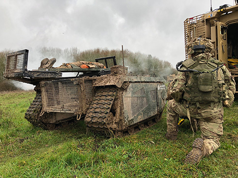
In December 2018 near Salisbury, England, four Milrem Robotics’ and QinetiQ TITAN unmanned ground vehicles (UGVs) were put through three weeks of rigorous tests by British troops during the Army Warfighting Experiment 2018 (AWE18).
The goal was to determine how new unmanned technologies can enhance soldier’s survivability and effectiveness on the modern battlefield.
The modular base can be adapted for various missions, including casualty retrieval. (Photo: Milrem Robotics)
The test was conducted in three phases: conduct combat operations without the benefit of new technologies; conduct combat operations using new technologies but without changing tactics; and, lastly, conduct combat operations using new technologies and adapting tactics according to the capability that the new technology provides.
The UGVs were used in a number of different roles with missions conducted in urban, open and forested terrain.
In remote-control mode, a command-and-control station allows the operator to receive real-time sensor data from the UGV and to transmit command data to the vehicle through a tactical data link. Various third-party sensor packages can be installed.
Of the four Milrem UGVs, two were deployed by Milrem Robotics and two by QinetiQ. The Milrem-fielded systems included one configured as a casualty evacuation and logistical support unit and a second unit equipped with a tethered multi-rotor drone pod provided by Threod Systems.
One of the four UGVs was TITAN Strike, a prototype system carrying a Kongsberg remote weapon station, fully controlled by a remote operator and using QinetiQ’s Pointer system as a means of integrating the capability with dismounted infantry.
The second system, TITAN Sentry, also enabled with Pointer, featured a Hensoldt-provided sensor suite including electro-optical and thermal-imaging cameras and a battlefield radar.
UUV Aquabotix Ltd. has been granted a United States patent for a “Remotely Operated Vehicle Camera Apparatus.”
Many underwater vehicles operate with a single stationary camera, an interior-based moveable camera or multiple cameras. Each of these configurations may have significant drawbacks and ultimately limit their functionality and usefulness, the company said.
For example, a forward-facing camera can be used for navigation but is limited if the operator would like to record information around the vehicle in a reconnaissance mission.
To address this challenge, Aquabotix developed a fully rotatable camera apparatus for attachment to its own or other vehicles. The camera apparatus can be mounted to the side of a vehicle and configured to rotate, enabling an operator to have a completely unobstructed 360-degree view in an underwater environment. This connector can also be used for mounting rotatable underwater light sources.
Based in Sydney, Australia, and Fall River, Massachusetts, Aquabotix is an underwater robotics company that manufactures and sells commercial and industrial-grade underwater drones for commercial, high-end consumer and military applications. It also offers commercially available swarming underwater drones.
By Simon Batzdorfer, Markus Bobbe, Martin Becker and Ulf Bestmann, Technische Universitaet Braunschweig
All images courtesy of the authors.
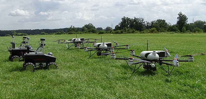
Autonomous vehicles equipped with different environmental sensors, such as optical or thermal camera or a lidar, performed a team survey controlled by a central ground station. The ground station serves as a user interface to define missions and tasks and also to visualize exploration task results online. 2D stitched orthophoto or lidar point clouds are transmitted for display and processing into 3D photogrammetry. Georeferencing data is gathered by an integrated GNSS/IMU positioning system.
In disaster scenarios such as fires, floods or search-and-rescue tasks, good situational awareness is indispensable for responders coping with a complex and often chaotic environment. In most cases, a prior known map data are outdated, and an efficient situational proceeding such as path planning or creation of a search pattern cannot be performed. This information can often only be gathered by manned exploration using ground or airborne systems, with limits on availability.
The research project Automated Navigation and Communication for Exploration (ANKommEn) seeks to create an automated unmanned system to close this gap by providing up-to-date scenario information while increasing the safety of human resources, using unmanned aerial (UAV) and ground-based (UGV) vehicles.
To provide up-to-date information of the desired destination area, all vehicles are equipped with identical positioning and communication hardware complemented by diverse sensors (RGB camera, infrared [IR] camera, lidar) for visual exploration. The visual sensor information is transmitted to a central ground station for visualization and/or analysis. To increase the advantages of the system, the unmanned systems should have a high grade of automation to reduce the workload of the operator so that only basic inputs have to be done by the operator. For example, just by marking a destination area and choosing a predefined task, the mission will be planned automatically, and after the corresponding waypoint-list has been transmitted to the vehicles, the mission will start.
Automated procedures of a UAV in particular require valid position information related to accuracy, availability and continuity. In exploration areas where the UAV operates in low altitude or using a UGV, the reception of the GNSS signal can be degraded by the topology (buildings and such). Using more than one GNSS can increase the availability of position information. Vehicle control, georeferencing environmental sensor data and exploration results all require high-frequency absolute position and attitude and heading information. This data is gathered by fusing GNSS and inertial measurment unit (IMU) data.
OVERALL SYSTEM DESIGN
The overall system consists of three UAVs, two UGVs (Opening photo) and a central ground control station. The latter serves as a central human-machine interface to monitor and manage cooperative operation of the UAVs/UGVs by an operator. Based on a priori known map data, exploration areas and tasks are defined and assigned to the UAVs/UGVs and will be updated with actual information of the visual sensors while performing a mission.
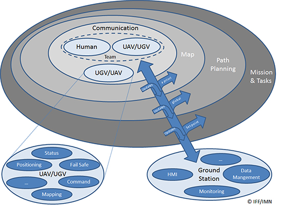
Figure 1 shows the interaction and information exchange between the different vehicles and sensors.
Figure 1. Diagram of interaction and information exchange.
All UAVs/UGVs are equipped with a navigation and communication unit (NAV/COM) and an environmental sensor payload (ENV) unit, including an RGB camera, thermal camera or a lidar respectively.
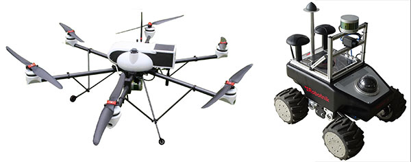
UAV/UGV and Sensor Hardware. The UAVs carry a payload of 2.7 kg (NAV/COM unit, mounted in the upper compartment, and ENV unit mounted under the UAV) and a flight time of up to 30 minutes (Figure 2, left). The payload sensors are carried and stabilized by a two-axis-gimbal. The environmental sensor payload unit is based on three different types of sensors, which are interchangeable between the different UAVs: RGB camera, lidar and IR camera.
For ground-based exploration, two four-wheel-drive UGVs carry a pan-tilt-zoom (PTZ) camera at the top of front chassis (Figure 2, right), and are equipped with a lidar and a thermal camera, or a stereo RGB camera, respectively.
Figure 2. UAV carrying a lidar (left) and UGV carrying lidar and IR camera (right).
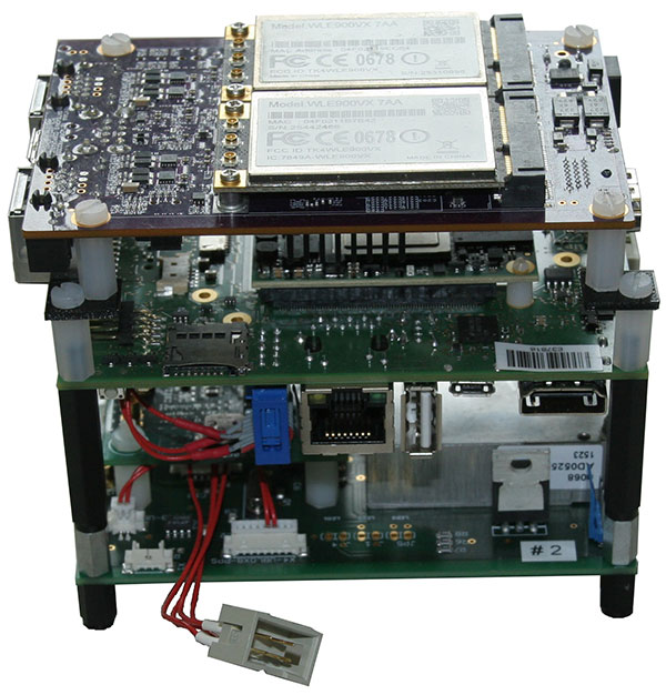
The navigation and communication unit mounted as a stack includes a network processor board for communication and data exchange between the UAV/UGV and the central ground and control station. An embedded processing board provides position calculation and GNSS-NTP-based time server. Data for the position calculation is provided by a custom-designed break-out-board (Figure 3).
Figure 3. Navigation and communication unit.
Data traced by these sensors cannot be sent directly to the ground station because of the huge data amount and the limited bandwidth of the communication link. Therefore, data from the sensors are preprocessed or compressed on a small form-factor personal computer and then transmitted to the ground station.
Ground Station. The ground station is the central device for command, control and visualization of the total system. It provides several options to display the data from the sensors and vehicles and a combination of them, and also provides automated path planning and calculation of the 3D reconstruction (photogrammetry) and online 2D stitched orthophoto.
Software Frameworks. The basic software for determining the vehicle’s state in 3D position, velocity, attitude and heading is established within a modular navigation software framework, with the option to process data of different sensors in real time as well as post-processing for data evaluation and development purposes. Several algorithms for sensor data fusion are implemented. The algorithm for IMU/GNSS fusion is based on an extended Kalman filter and also provides an IMU data-based state vector, stabilized by GNSS information, for the visual sensors. This state vector is published by using the robot operating system (ROS), a framework for inter-process communication based on a TCP or UDP publisher/subscriber concept. The visual sensors and embedded PCs subscribe to different ROS messages, for example, the state-vector-message or information of other sensors.
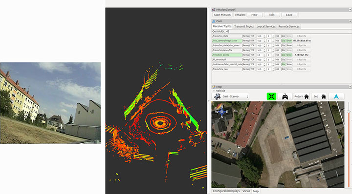
Figure 4 shows examples of the actual camera view from the UGV, and point cloulds and map generated by the UAV. The software layout can be customized by the user.
Figure 4. From left to right: the actual view by the PTZ camera onboard the UGV, the point cloud gathered by the UAV’s lidar, and the mission parameters and map of an aerial view.
POSITIONING OF UAV AND UGV
Automated operation of UGVs and UAVs requires valid position as well as attitude and heading information. In the case of using only one GNSS, signal quality and availability can be degraded by the environment (buildings) and can result in less precise or even a lack of position information.
GNSS Multi-Constellation. To overcome the risk of poor availability of GNSS-based position information, parallel usage of different GNSS can raise the number of received satellite signals: GPS, GLONASS, the evolving Galileo and BeiDou. When using a multi-constellation approach for positioning, one has to take care of several differing aspects between the GNSS. Each system uses a different geodetic reference frame and time basis. Measurements gathered from another GNSS system must be transformed into the reference frame of the desired system. The geometric distribution of the satellites is improved by using more than one GNSS constellation, indicated by a lower dilution-of-precision value.
The navigation software framework is designed for real-time computation and also for post-processing. In post-processing, the recorded sensor data is streamed to the software framework with the option of changing several parameters and settings for calculation. One option is to exclude satellites at low elevation from position calculation by changing the cut-off elevation for these satellites. This parameter will be changed to simulate environmental conditions that block receiving GNSS signals, like buildings within urban scenarios, to compare the availability of received GNSS signals for single- and multi-constellation-based position calculation.
Recorded data of a real-world test serves as the database for the post-processing with different cut-off elevation parameters. At the beginning of the field test, there was a short initialization period to boot the OS and to start basic processes for positioning. After that, a predefined mission was flown and the GNSS measurements have been saved for the described post-processing.
Post-processing has been performed with different cut-off elevation parameters of 5° up to 35°. In the case of 35°, the number of GPS satellites is reduced to the minimum for position calculation of four, in contrast to 5–7 available satellites for a multi-constellation based solution.
GNSS/IMU Fusion. Using the GNSS multi-constellation approach can increase availability of position information. For attitude and heading determination, an IMU is nevertheless indispensable. Additionally, the frequency of the pure GNSS-based positioning information is usually between 1 Hz to 5 Hz within the described hardware setup. Meaningful georeferencing of the environmental sensors requires much higher frequency position and attitude information.
The IMU provides high-frequency 3D measurements of accelerations and angular rates. Using common strapdown algorithm processing, high-frequency position, velocity, attitude and heading information is provided in real time. Due to the short time stability of pure inertial navigation, the GNSS positioning results are used for aiding purposes within the Kalman filter’s update step. To overcome the absence of GNSS aiding information even when using multi-constellations, there are mainly two options. First, a short coasting period is possible after the data fusion has reached a steady state.
Second, due to the highly modularly design of the navigation software framework, it is possible to use position or attitude increments from environmental sensor data processing for aiding the IMU.
The vehicle’s state vector is then distributed with high frequency within the system for georeferencing measurements of the environmental sensors, especially the RGB camera and the lidar for photogrammetry and simultaneous location and mapping (SLAM) applications.
PHOTOGRAMMETRY AND SLAM
In major fire scenarios, maps can be out of date. Therefore, techniques have been developed to gather a 2D overview based on several single RGB pictures taken and processed on board a UAV and transmitted to the ground station via data links. Additional processing of a 3D reconstruction of the scenario is an integrated feature within the ground station. Both approaches were implemented to get an automated rapid aerial mapping solution.
In the case of the 2D overview, SLAM algorithms, often used in robotic research, are adapted for this specific use case. These algorithms provide good results for a rapid aerial mapping solution to get an overview of the scenario, because the map is updated incrementally with every new image, but they are less precise, which can be compensated for by using the photogrammetric 3D reconstruction. The live mapping (SLAM) approach is based on the ORB-SLAM algorithm, and the photogrammetry-based approach uses commercially available photogrammetry software.
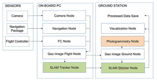
The systems, on the UAV for 2D and for 3D on the ground station, use the ROS framework for processing the visual sensor data and the described techniques for positioning, georeferencing and attitude determination. For data exchange between these frameworks, several software interfaces have been implemented. Figure 5 displays a flowchart of the implemented workflow.
The sensor/input data is received by corresponding nodes on the aerial vehicle. After adding the camera pose information to the image in the geo-image flight node, the image is sent to the geo-image ground node on the ground station. The SLAM process is separated into two parts. The SLAM tracker node calculates the transformation between images, and the SLAM stitcher node applies the transformations. The transformed images are displayed by the visualization node. The photogrammetry node receives the georeferenced images, stores the data, and initiates the photogrammetric processing once the survey is finished. The results can also be displayed by the visualization node and exported in a desired format.
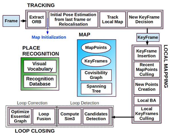
Visual SLAM. Computer vision-based algorithms have developed rapidly over the last few years. One method estimates a pose by using monocular image processing, known as parallel tracking and mapping (PTAM). This integrates a bundle adjustment and separates the tracking and the mapping procedure into different threads, leading to a real-time capable framework. These basic PTAM principles have been integrated into a robust loop-closing and another method of relocalization, known as Oriented FAST and Rotated BRIEF (ORB SLAM), shown in Figure 6. Here, tracking, local mapping and loop closing are separated into different threads (gray boxes), with the main map and place recognition in the middle.
Figure 6. ORB SLAM system overview [Mur-Artal, 2015].The tracking thread predicts the current pose from the last known position and movement by using a constant velocity model and performs a guided search of map points. If these points are found near the estimated position, the velocity model is valid and the tracking procedure continues. Otherwise, the tracking is lost and a relocalization in the global map starts by using a subset of features, which are increased after detection of corresponding features in other keyframes to optimize the camera pose and, finally, the tracking procedure continues. The last step of this procedure is to decide whether the current frame contains enough information to be inserted as a new keyframe for further calculations.
To mark a frame as a new keyframe, the frame must fulfill all of the following conditions:
More than minimum number of frames has passed.
Local mapping is on idle or condition 1 fulfilled.
A minimum number of 50 points is observed.
A maximum of 90% of the features is already observed by the other frames.
When a new keyframe is passed to the local mapping procedure and inserted as a node into a co-visibility graph structure, new correspondences are searched in the connected keyframes to triangulate new points. Based on the information accumulated during the tracking, a point culling keeps only high-quality points in the map as well as a culling of redundant keyframes.
Then a loop closing is performed. This is one of the main improvements compared to PTAM. If a loop is detected, the drift accumulated in the loop is computed, and both sides of the loop are aligned and visible points are fused. In a final step, a pose graph optimization is done to achieve global consistency.
This information of the 3D camera pose is used to generate a 2D orthophoto in real time while the vehicle is flying. To create a 2D orthophoto, a common reference frame is approximated, which is orthogonal to all camera measurements. The projection is performed by using a projection model based on a pinhole camera.
After the compensation and distortion, the whole image can be stitched to the current global map.
Photogrammetry. This approach uses off-the-shelf photogrammetric processing software. The processing is triggered automatically when the survey is completed and all images are transferred to the ground station via data link. For georeferencing of the images, the camera location and the inner camera geometry were written to the EXIF file of each image by the geo-image ground node (Figure 5). To ensure an acceptable compromise between orthophoto quality and the required processing time, an analysis regarding the impact of the most relevant processing parameters has been performed.
Figure 5. ROS node layout with SLAM (green) and photogrammetry workflow (red).
The photogrammetry process consists of four steps:
camera alignment (optimizing the homographic equation)
mesh creation by generated tie points
orthophoto creation (dense cloud or digital elevation model)
export.
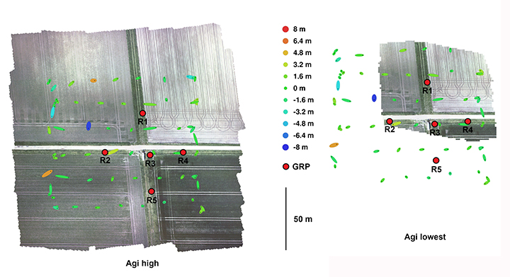
Analyses and Evaluation. To evaluate the correct workflow of both approaches of 2D live-stitching and the 3D photogrammetry, a real-world flight test above agricultural cropland has been performed. The results of both approaches are shown in Figure 7 and Figure 8. Generally, agricultural cropland and its mean textured surface pose a challenge for mapping processes because of the limited number of trackable features.
Figure 7. Orthophotos created with the profiles high and lowest (including ground reference points).Figure 8. Orthophotos created with 2D live stitching approach of cropland.
Four predefined profiles were used to cover the requirement of compromise between processing duration and quality of the generated orthophoto. Each profile level generates a corresponding level of alignment accuracy and mesh face count: lowest, low, medium and high.
To estimate the accuracy of the created maps by the different profiles, five ground reference points (GRPs) were distributed over the mission area. The location of the GRPs was determined using a RTK-GNSS system leading to a horizontal RMSE below 2 cm. To enable robust processing for this scenario, the overlap and the sidelap was chosen to be 70%. A ground-sampling distance (GSD) of 2 cm was needed to identify the GRPs. This resulted in a mission consisting of six times 100-meter (m) lines with a distance of 25 m in an altitude of 60 m over ground. During the flight time of 4.5 minutes, 271 images were taken.
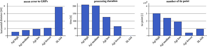
To compare the profiles, they were triggered one after another with the same set of images. The created results are shown in Figure 7. All profiles resulted in consistent solutions and were successfully georeferenced. The map based on the lowest profile could not recreate the complete area (Figure 7, right). The remaining profiles led to similar results without notable differences to visual inspection. The processing time varied between 1.2 and 3.6 minutes. A comparison of this and other criteria is given in Figure 9.
Figure 9. Evaluation and comparison of defined software profiles and visual SLAM.
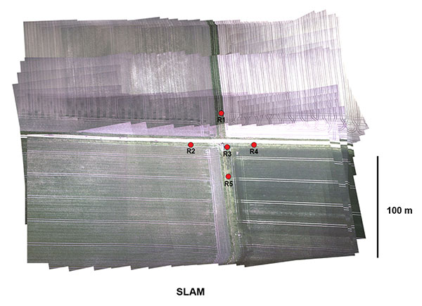
The created final image of the SLAM pipeline is shown in Figure 8. The image was updated with every new image and was therefore finished before the UAV landed. The mean location error measured using the reference points was about 8 m, significantly larger than the errors observed in the photogrammetry results. In Figure 9 the results are contrasted to the results of the photogrammetry approach.
While the mean error in the low profile is half as high as in the lowest profile, the calculated errors using the medium and high profiles are not enhanced significantly. The number of tie points created by the lowest profile is an order a magnitude lower compared to the other three profiles.
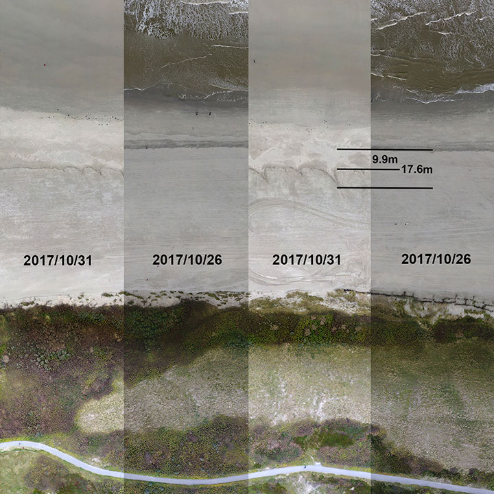
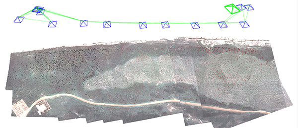
We conducted flight tests on Langeoog island in the North Sea, to gather information on efforts to protect the island’s coastline from water erosion. For this reason, sand was selectively washed up to the coastline by dredgers at the beginning of October 2017. Between Oct. 26 and 31, due to severe weather with a storm flood, a huge erosion of the washed up sand occurred, and the result is shown in Figure 10. The level of erosion was determined by comparison of the orthophoto of the same area. The dislocation averaged out to 9.9 m with some peaks up to 17.6 m.
Figure 10. Evaluation of erosion.
The 3D photogrammetry provides a more detailed image compared to the image of the 2D-live-stitching approach (Figure 11), but both approaches can provide the desired information of the area.
Figure 11. Result of the SLAM approach with camera poses and tracked features.
Both implemented approaches were successfully integrated to get the desired fully automated rapid aerial mapping solution. This also includes the basic tasks of the automated mission planning, camera control, image transport to ground station, automated processing and the visualization of the results.
CONCLUSION
The benefits of multi-constellation GNSS positioning have been demonstrated with a focus on UAVs and UGVs operating in catastrophic scenarios, especially where GNSS signal reception might be blocked. This position information is also used for georeferencing of images and visual reconstruction of the area. The overall system has demonstrated the capability of an automated orthophoto generation. Both implemented mapping methods — a 2D live stitching and a 3D photogrammetry — provided results that fulfill the requirements to get an instantaneous 2D overview and a contemporary 3D reconstruction of the area.
ACKNOWLEDGMENTS
This work was done within the joint research project ANKommEn, funded by the German Federal Ministry of Economic Affairs and Energy, administered by the Space Administration of the DLR (funding code: 50NA1518). Project partners are the Institute of Flight Guidance (IFF), the Institute of Mobile Machines and Commercial Vehicles (IMN) — both part of Technische Universität Braunschweig — and AirRobot GmbH & Co. KG, a German manufacturer of multirotor UAVs. The professional fire brigade of Braunschweig and the Lower Saxony Water Management, Coastal Defense and Nature Conservation Agency also participate as associated project partners.
SIMON BATZDORFER holds a Dipl.-Ing. in mechanical engineering and is a research engineer at the Technische Universitaet Braunschweig, Institute of Flight Guidance (IFF).
MARKUS BOBBE holds a M.Sc. in aerospace engineering and is a research engineer at the Braunschweig IFF.
MARTIN BECKER holds a Dipl.-Ing. in aerospace engineering and is a research engineer at the Braunschweig IFF.
ULF BESTMANN received his Dr.-Ing. in mechanical engineering from TU Braunschweig. He is head of the navigation department of the IFF. He co-founded the company messWERK GmbH, a service provider in flight testing and certification.
Built for outdoor operations, Duro combines a rugged enclosure with centimeter-accurate positioning. Leveraging design principles typically used in military hardware, the GNSS sensor is protected against weather, moisture, vibration, dust, water immersion and unexpected circumstances that can occur in outdoor long-term deployments. In addition to its ruggedness, Duro is ready to connect right out of the box. Primary industries for this product include: robotics, precision agriculture, mapping, military, outdoor industrial and maritime.
Photo: Swift NavigationDuro incorporates:
Dual-frequency RTK GNSS
Tough, military-grade hardware
IP67 rating
Weatherproof external enclosure design with M12 standard-sealed connectors
On-board MEMS IMU and magnetometer
Future-proof hardware with in-field software upgrades
Protected IO, including RS232 Serial Ports, 100mbit Ethernet, Event Inputs, PPS, PV, CANBus
The unmanned ground vehicle market (UGV) is estimated to be valued at $1.49 billion in 2016 and is projected to reach $2.63 billion by 2021 with a CAGR of 12.14 percent during the forecast period, according to a new market report.
The report, published by MarketsandMarkets, examines the unmanned ground vehicle market (UGV). The base year considered for the study is 2015, and the forecast period is 2016 to 2021.
The title of the report is “Unmanned Ground Vehicle Market by Application (Defense-ISR, EOD, Crew Integration, Commercial-Agriculture, Field, Domestic, Transportation), Mobility (Wheeled, Tracked), Size, Component, Modes of Operation, Payload & Region — Global Forecast to 2021.” The 193-report includes an in-depth table of contents, 86 market data tables and 64 figures.
The increasing demand for UGVs in the commercial and defense sectors and technological innovations that have created a demand for UGVs to perform complex operations with minimal human intervention and better safety are the major factors driving the UGV market, according to the company’s analysts.
Based on application, the UGV market has been segmented into commercial and defense. The commercial segment of the UGV market is projected to grow at the highest CAGR till 2021. This growth is driven by the increasing demand for domestic and industrial UGVs.
Based on size, the unmanned ground vehicle market has been segmented into micro UGVs, small UGVs, medium UGVs, and large UGVs. The small UGV segment of the unmanned ground vehicle market is projected to grow at the highest CAGR during the forecast period. The demand for small UGVs from both the commercial and defense sectors for their capabilities has enhanced the growth of this segment.
Wheeled UGV and tracked UGV have been considered under the mobility segment of the unmanned ground vehicle market wherein the tracked UGV segment is projected to grow at the highest growth rate. Tracked UGVs are more versatile than wheeled UGVs as they can be operated on difficult terrains and can carry higher amounts of loads, thus leading to its higher demand.
Autonomous mode
In 2012, a second unmanned MTVR was built to evaluate multiple UGVs supervised by a single operator.
The unmanned ground vehicle market is segmented into tethered, tele operated, semi- autonomous and autonomous, based on mode of operation. The autonomous segment is estimated to have the largest share with the highest CAGR in this segment during the forecast period due to their capability of operating without any human intervention.
The software component segment is estimated to grow at the highest CAGR during the forecast period compared to the hardware segment as the customers are looking for sophisticated UGVs, which require advanced software systems.
The UGV market Asia-Pacific is projected to grow at the highest growth rate during the forecast period. The rapid growth of the Asia-Pacific market can be attributed to the increasing investments to develop UGVs for defense as well as commercial applications. The investments are mainly driven by the developments in China, India, Japan and South Korea, which are among the fastest-emerging economies in the world.
Major players
The major players in this market have been identified to be QinetiQ Group Plc. (U.K.), iRobot (U.S.), Northrop Grumman (U.S.), Oshkosh Corporation (U.S.) and Lockheed Martin (U.S.), among others.
The report segments and analyzes the unmanned ground vehicle market on the basis of mode of operations (tethered, tele-operated, semi-autonomous and autonomous), mobility (wheeled and tracked), size (micro, small, medium and large), payload (sensors, lasers, camera, radars and others), application (defense and commercial), and component (hardware and software) and maps these segments and sub-segments across the major regions of the world, namely, North America, Europe, Asia-Pacific, the Middle East and the rest of the world (comprising Latin America and Africa). Brief information on the research methodology for the report can be found in the report description provided on website.
Related Reports
“Military Robots Market by Platform (Airborne, Naval, Land-based), Application (Warfield, Pick ‘n’ Place, Firefighting, Voice-controlled Robotic Vehicle, Metal Detector Robotic Vehicle, Others), & Region — Global Forecast to 2020”
“Unmanned Aerial Vehicle (UAV) Market by Application, Class (Mini, Micro, Nano, Tactical, MALE, HALE, UCAV), SubSystem (GCS, Data Link, Software), Energy Source, Material Type, Payload and Region — Global Forecast to 2022”
Unmanned tactical wheeled vehicles for logistics and route clearance missions provide a significant force protection advantage — removing personnel from targeted vehicles, extending standoff distance from explosives, and empowering a single operator to simultaneously supervise multiple unmanned assets in convoy. This article discusses some of the enabling technologies and the motivations behind them, for safer and more efficient logistics and route clearance operations in a tactical environment.
By John Beck
Unmanned ground vehicles (UGVs) that can semi-autonomously operate over complex terrain represent a promising technological enabler for effective logistics supply and route clearance functions.
Oshkosh Defense has developed autonomous systems for tactical wheeled vehicles (TWVs), working closely with government agencies on autonomous appliqué systems with developed tactics, techniques and procedures that together offer a more efficient and less perilous means to perform critical missions in theater.
The system is designed to be unobtrusive, so that the host platform retains its original mobility, payload capacity, survivability (minimal impact to armor) and manual operation. By upgrading existing fleet vehicles with the capability for unmanned operation, the TerraMax UGV technology can economically and innovatively deliver force protection and force multiplication advantages.
MOTIVATION
Improvised explosive devices (IEDs) pose one of the greatest threats to today’s ground forces carrying out logistics missions in hostile environments. While the up-armoring of tactical vehicles has been effective in reducing casualties, the warfighter remains at risk to the ever-increasing net explosive weights. By fielding UGVs, militaries will be able to remove personnel from TWVs and mitigate the danger of armor overmatch.
To increase efficiency of a reduced force structure, UGVs will serve as force multipliers, enabling a warfighter in a protected vehicle to supervise the coordinated operation of multiple UGVs from a safe standoff distance. These UGVs will be able to operate for extended periods of time, during day and night, and through dust and adverse weather conditions without fatigue or loss of awareness. UGVs will precisely maintain vehicle separation, enabling greater security, improved efficiency and fewer collisions.
Environment Drives Design. To be sustainable in theater, unmanned TWVs must equal their manned counterparts in performance, reliability and mobility in austere tactical environments. For the purposes of overcoming complex terrain, prevailing TWVs are engineered to be capable of feats such as fording 1.5 meters of water and traversing 60% gradients and 30% side slopes.
In addition, these vehicles are expected to operate across broad temperature extremes in dusty, sandy or muddy environments, enduring all manner of precipitation, vegetation and weather conditions. The stringent operational requirements of expeditionary forces influence both individual component selection and overall system design for manned vehicles; the same is true for an unmanned appliqué complement, which must be capable of interpreting and operating in these harsh and complex environments.
ENABLING FULL MOBILITY
TerraMax UGVs are actuated by a tightly integrated drive-by-wire system enabling precise vehicle control using MIL-STD system components to ensure reliability and durability in a tactical environment. It is a safety-critical system that integrates with relevant vehicle components, including steering, engine, brakes, transmission and auxiliary driving functions (such as the central tire inflation system, drive line locks and engine braking), preserving the broad mobility characteristics of the host platform.
The drive-by-wire system both enables higher level robotic control functionality and provides independent benefits in the form of advanced driver assistance system (ADAS) features to benefit manual driving, reducing accidents and collisions.
To facilitate detecting errors absent in an in-vehicle driver’s intuition, the drive-by-wire system communicates with core vehicle diagnostic sensors. It also utilizes add-on sensors that enable monitoring of vehicle and auxiliary subsystem attributes such as hydraulic and pneumatic pressures, ambient and local temperatures, fuel and fluid levels, battery charges and power usage.
All of this data is accessible from the control interface. In addition, threshold values are configured for each monitored sensor such that an operator will be advised if any components exceed warning or critical levels. This ensures that severe conditions do not go unnoticed by an operator, who could be at a distance beyond direct line of sight and may be preoccupied or otherwise unable to dedicate full attention to monitoring multiple UGVs downrange.
Perception Sensors. The TerraMax UGV sensor suite (Figure 1) uses multiple sensor modalities to provide robust sensing capability. The primary sensor for analyzing terrain and obstacles is the high-definition (HD) laser detection and ranging (LADAR), with 64 scanning lasers sweeping 360 degrees.
Figure 1. Sensor suite aboard TerraMax UGV.
In addition, radars are positioned around the vehicle to detect moving obstacles such as other vehicles. Wide-angle cameras are also positioned around the periphery to give a remote operator the ability to visually check vehicle surroundings.
A navigation solution using GPS and an inertial navigation system (INS) supports the ability to drive accurately even with limited GPS signal availability. On the roof facing forward are two cameras used for teleoperation of the vehicle: a wide dynamic range (WDR) camera for daytime use and a short wavelength infrared (SWIR) camera for night operations.
Perception Software. The TerraMax UGV perception software leverages a multi-sensor suite that compensates for the weaknesses of one sensing modality with the strengths of another; for example, relying upon the dust-penetrating ability of automotive radar when LADAR and visible-spectrum camera feeds are obscured.
The perception software uses several modules to interpret the world around it: terrain detection, which assesses roughness of the nearby terrain and informs the selection of appropriate speeds; terrain classification, which distinguishes among foliage, dust or other airborne obscurants and obstacles (Figure 2) and enables traversability appraisals of the surrounding area; and dynamic obstacle detection, which tracks vehicles and dismounts and allows the UGV to exhibit defensive driving behaviors. This software also affords situational awareness and a means for remote supervision of the vehicle by providing processed output for display at the operator control unit.
Figure 2. Perception system display in the TerraMax UGV.
In addition, fused sensor data are combined using novel registration techniques that couple the vehicle’s perception of its surroundings with ground-truth geospatial mapping data to correct for errors in GPS position estimates. This allows the system to be enhanced by, rather than dependent upon, GPS and vehicle-to-vehicle data. Government testing has demonstrated the ability of the TerraMax UGV system to endure complete GPS blackout for more than 19 kilometers with no noticeable impact on mission performance.
Key features of the perception system are:
operable in all environments under all weather and lighting conditions;
installed inconspicuously on the base vehicle and capable of covert modes of operation;
able to deliver reliable system performance under extreme GPS degradation or denial.
Motion-Planning Software. This onboard software takes in an operator’s objectives regarding routing, speed and inter-vehicle spacing as entered during mission planning or on-the-fly. It consequently observes processed sensor data from the perception system and calculates and executes speed and steering commands that guide the vehicle along an optimal path. The motion planning software has been developed with machine learning techniques to emulate smooth human driving behaviors such as avoidance of obstacles and terrain hazards while maintaining appropriate vehicle speed on various terrains.
Key features of the motion planning system are:
intelligent speed and path selection in all terrain, including secondary roads and trails;
capability of sustaining high platform mobility (for example, handling fording and grade climbs);
ability to support high operational tempo (OPTEMPO).
Modes of Operation. When enabled for unmanned operation, a TerraMax UGV can be placed in one of three different modes: semi-autonomous, follower,or tele-operation. The mode selection for each vehicle is controlled from the primary OCU that can be installed in any other tactical or combat vehicle.
In semi-autonomous mode, basic waypoint navigation via GPS coordinates is supported. In addition, mission plans can be created that include information such as check-points, intended vehicle separation distances, speed limits by region, and exclusion zones. These missions are planned from the OCU on a route map that is produced from standard geospatial vector data and predefines the roads on which the UGVs may travel.
This feature, illustrated in Figure 3, allows for on-the-fly mission planning and route changes by selecting “via points” on the road network (similar to a Google Maps functionality) that are automatically connected into a full route plan.
Figure 3. Waypoint navigation.
This requires significantly less effort than manually selecting each individual waypoint for each unmanned vehicle. Once a route has been established, the UGVs traverse the assigned road using their fused global position estimates (leveraging GPS signals as well as the sensor-enhanced map registration to stay on the road) and take advantage of the data link between the vehicles to ensure they maintain prescribed leading and following distances.
In follower mode, no predetermined mission plan is required; a manned vehicle such as the command and control vehicle (C2V) is simply designated as the leader by the operator, and the unmanned vehicles will follow anywhere on the roadway (while still performing intelligent road-keeping and obstacle detection). Two modes of leader tracking are supported: coordinate-based and direct observation.
In the primary mode of coordinate-based following, the lead vehicle transmits its GPS-based position to the follower via the radio data link. The follower vehicle correlates this position to the route map and subsequently appends a waypoint to its upcoming path that would bring the follower to a position on the road directly behind the leader.
In tele-operation mode, an operator assumes remote control of a single UGV and directly commands vehicle speed, steering and other functions via a rugged handheld controller. The operator has a selection of either live video feeds, or an augmented reality view supported by perception data overlaid on aerial imagery, displayed on the OCU display.
OPERATOR CONTROL UNIT
The operator control unit (OCU)hardware and software (Figure 4) are designed to be installed in any other tactical vehicle, along with a low-cost GPS receiver and radio data link that enables communication with multiple TerraMax UGVs from up to 1 kilometer. The OCU allows a single operator to manage coordinated mission command and control of mixed convoys comprised of manned and unmanned vehicles. Route information and convoy behaviors can be pre-planned, saved, loaded and modified as needed during operations.
Figure 4. TerraMax UGV operator control unit.
Touchscreen and function keys allow rapid input using relevant and contextual menus including configurable preset values. Live position and status of each vehicle is displayed on a zoom-able overhead map, and camera feeds from any of the UGVs may be displayed in a familiar picture-in-picture format.
A distilled version of the perception information can be selectively overlaid, aiding the operator’s situational awareness of the vehicles’ surroundings. Remote control and tele-operation is supported using a ruggedized game-style controller for situations when the operator wants direct control of steering and throttle.
TRAINING
Because pre-deployment training opportunities may be limited and any near-term requirement for highly specialized troops is untenable, ease of skill acquisition is critical. In two warfighter experiments for the U.S. Marine Corps Warfighting Lab’s recent Cargo UGV project, the TerraMax system was demonstrated to be operable by veteran motor transport operators after a three-day training course comprising classroom instruction, a realistic desktop simulation environment, and hands-on exercises with the vehicles.
The capstone experiment integrated two TerraMax UGVs into a manned logistics convoy, which was then subjected to a variety of realistic operational scenarios including unexpected road blocks, simulated IED strikes and night operations. Results showed the novice users were able to successfully complete mission objectives using the unmanned systems.
At the conclusion of each of the warfighter experiments for the Cargo UGV project, operators believed they could comfortably control three to five UGVs from a single user interface without suffering cognitive overload.
CONCLUSION
With onboard sensing and decision-making, these unmanned TWVs can provide a force multiplier by empowering a single operator to simultaneously supervise several unmanned assets traveling in convoy, operating semi-autonomously for extended-duration movements. This advantage is significant because it permits more efficient completion of missions by lowering both risk to, and demand for, ground forces.
The procurement, operations and maintenance costs for a robotic capability on TWVs will also be minimized by modernizing existing fleet vehicles with an appliqué kit, but to become viable in theater operations, unmanned TWVs must be able to contend with the same performance, reliability, and mobility in the austere tactical environments as their manned equivalents.
TerraMax UGV technology can be applied to any tactical vehicle and has already been prototyped on the Medium Tactical Vehicle Replacement (MTVR), Palletized Loading System (PLS), Family of Medium Tactical Vehicles (FMTV) and the Mine Resistant Ambush Protected (MRAP) All-Terrain Vehicle (M-ATV).
TERRAMAX HISTORY
Oshkosh has been developing and fully autonomous UGVs since 2003. Among its several generations:
In the 2005 Defense Advanced Research Project Agency (DARPA) Grand Challenge, TerraMax was one of only five vehicles to complete the entire 132-mile course.In 2007, the TerraMax vehicle was one of 11 qualifiers at the DARPA Urban Challenge.In 2012, a second unmanned MTVR was built to evaluate multiple UGVs supervised by a single operator.In 2013, TerraMax UGV M-ATV demonstrated capabilities for route-clearance missions. (Featured on the June 2016 cover.)
ACKNOWLEDGMENT
This article is based on a technical presentation given at AUVSI xPONENTIAL, May 2016 in New Orleans.
John Beck is chief engineer, Unmanned Systems, at Oshkosh Corporation.
Maynard J. Factor of Micro Systems, an unmanned systems division of Kratos Defense, explains the company’s unmanned ground system technology at the Association of Unmanned Vehicles International‘s Xpontential 2016 show, held May 2-5 in New Orleans. Micro Systems’ leader/follower capabilities allow an unmanned, autonomous Impact Protection Vehicle to follow a manned lead vehicle.
Carnegie Mellon University and Sikorsky Aircraft researchers have used an autonomous helicopter and an autonomous ground vehicle to demonstrate for the U.S. Army that ground and air robots can perform complex, cooperative missions, the university announced Jan. 20.
During the Oct. 27 demonstration, an unmanned Black Hawk helicopter picked up an unmanned ground vehicle (UGV), flew a 12-mile route, delivered the UGV to a ground location and released it. The drop-zone collaboration promises to keep warfighters out of harm’s way, enabling them to perform missions more effectively.
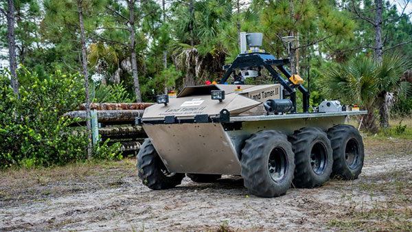
An unmanned Black Hawk delivers an autonomous ground vehicle to a remote site in a demonstration for the U.S. Army of a joint robotic air-ground mission. (Photo: CMU)
The Black Hawk was equipped for autonomous operation by Sikorsky, a Lockheed Martin Co. It delivered a Land Tamer autonomous unmanned ground vehicle from Carnegie Mellon’s National Robotics Engineering Center (NREC) to a remote site, where the vehicle performed environmental monitoring for potential contamination, the type of robotic mission that could prevent warfighters’ exposure to hazardous conditions, such as chemically or radiologically contaminated areas.
“We were able to demonstrate a new technological capability that combines the strengths of air and ground vehicles,” said Jeremy Searock, NREC technical project manager. “The helicopter provides long-range capability and access to remote areas, while the ground vehicle has long endurance and high-precision sensing.”
The demonstration took place at Sikorsky’s Development Flight Center in West Palm Beach, Florida, for the Army’s Tank Automotive Research, Development and Engineering Center (TARDEC).
Once the helicopter lowered the vehicle to the ground, the Land Tamer drove itself off its transport platform to commence its leg of the mission. The vehicle, equipped with sensors for detecting chemical, biological, radiological or nuclear contamination, then found and surveyed several potentially contaminated sites, autonomously traversing six miles in the process.
When the vehicle sensors detected potential contamination, operators were able to switch the vehicle from autonomous operation into a tele-operated mode for a more detailed exploration of the site.
The helicopter delivered the Land Tamer, Carnegie Mellon’s unmanned ground vehicle. (Photo: CMU)
“The teaming of unmanned aerial vehicles and unmanned ground vehicles, as demonstrated here, has enormous potential to bring the future ground commander an adaptable, modular, responsive and smart capability that can evolve as quickly as needed to meet a constantly changing threat,” said Paul Rogers, TARDEC director.
NREC has developed the unmanned Crusher off-road vehicle for the Defense Advanced Research Projects Agency (DARPA), the Advanced Platform Demonstrator for TARDEC and a tactical unmanned ground vehicle, called Gladiator, for the U.S. Marines, as well as advanced off-road autonomous driving technology. NREC was also part of CMU’s Tartan Racing Team that won the $2 million 2007 DARPA Urban Challenge robot race with its autonomous SUV called Boss.
The Black Hawk helicopter used in the demonstration was a UH-60MU model, equipped for “fly-by-wire” operation. Sikorsky installed its Matrix technology, which it has been developing since 2013.
In the demonstration, a Black Hawk helicopter equipped with Sikorsky’s Matrix autonomy kit flew NREC’s Land Tamer all-terrain vehicle, slung beneath the aircraft in a specially designed cage, to a remote area.

 Built for outdoor operations, Duro combines a rugged enclosure with centimeter-accurate positioning. Leveraging design principles typically used in military hardware, the GNSS sensor is protected against weather, moisture, vibration, dust, water immersion and unexpected circumstances that can occur in outdoor long-term deployments. In addition to its ruggedness, Duro is ready to connect right out of the box. Primary industries for this product include: robotics, precision agriculture, mapping, military, outdoor industrial and maritime.