Tag: xNAV650

  • OxTS: Meeting accuracy demands

    OxTS: Meeting accuracy demands

    Mobile mapping using an OxTS xNAV650 INS and lidar sensor. Photo: OxTS
    Mobile mapping using an OxTS xNAV650 INS and lidar sensor. Photo: OxTS

    We discussed mobile mapping with Jacob Amacker, application engineer, OxTS.

    How do you define “mobile mapping” as opposed to “surveying”?

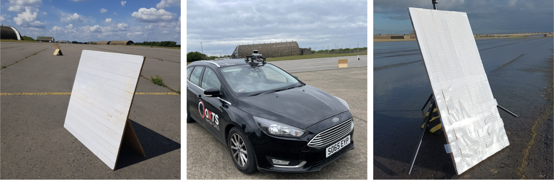
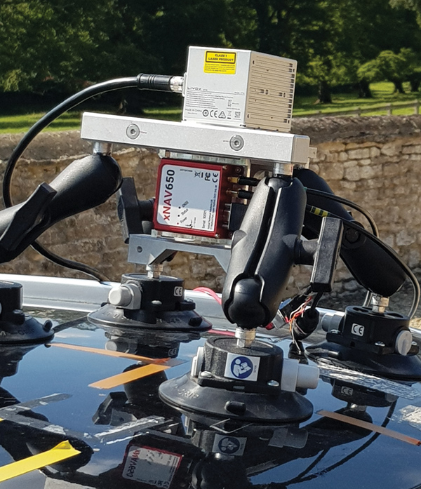
    We use the two terms interchangeably. Each one has a different connotation depending on where you are in the world and both can be useful. We use them to cover a broad range of use cases, but “mobile mapping” is used more specifically for land-based mapping of the environment. A typical application might be a van equipped with an INS [inertial navigation system] and lidar sensors.

    “Surveying” can be used a bit more generally, applying to aerial or pedestrian-based mapping, but it does have the connotation of static mapping, which we do not typically handle.

    What are your main markets for mobile mapping?

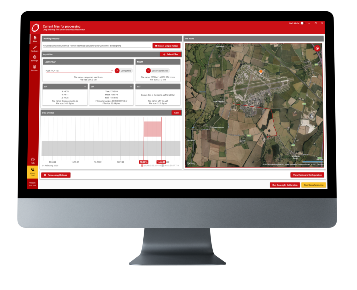
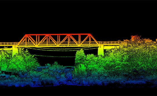
    It is very hard to say. The world of mobile mapping is so diverse. However, lidar mapping could be seen as both the largest and the fastest-growing market in the surveying world as lidar has become widely affordable. Although our technology can be used with any surveying devices, at OxTS we particularly like to use lidar and are focusing on getting the best results from lidar data. This has included making our own point-cloud georeferencing software to maximize the potential of our navigation data in making point clouds.

    What are the main differences between your devices for aerial mapping and for ground-based mapping?

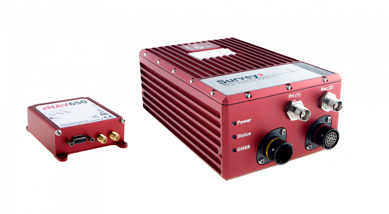
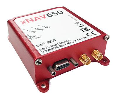
    We use the same INS device for both ground and aerial mapping. For use on manned aircraft, we would always recommend our highest accuracy system with the best IMU, the Survey+. The main source of inaccuracy in survey data will come from the IMU error over the range to the objects. Because most of this range is the aircraft’s altitude, this error is quite significant. For land-based mapping work, the measurements provided by the lighter and smaller xNAV650 are still suitable for many high-precision applications.

    GNSS-INS integration has been done for decades. What is new and what are the remaining challenges?

    It is now much more affordable to have very high-grade IMUs and GNSS receivers. Nevertheless, there will always be further improvements to be made to how the data streams are combined. On a similar note, other navigation aiding sources are increasingly being considered to supplement the IMU and the GNSS receiver — such as wheel speed sensors, lidar, camera odometry and others that can also be integrated to stabilize and improve the navigation data. Overall, it is very exciting what is yet to come out of INS technology. In recent years, it has become so good that people expect more and more from it, and this demand must be met. What happens when GNSS drops out? We are seeing increasing development to make the navigation data robust against challenges of any environment.

    Given the IMU’s drift, for how long can your system function at an acceptable level in case of a GNSS outage?

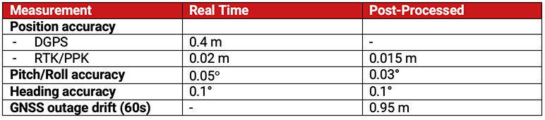
    It is difficult to put a number on what kind of drift is acceptable, as it depends on the application and the end-user requirements. Typically, half a meter of drift in one minute of GNSS-outage might be the goal for some of the higher-grade surveyors. Still others might only be satisfied with negligible drift.

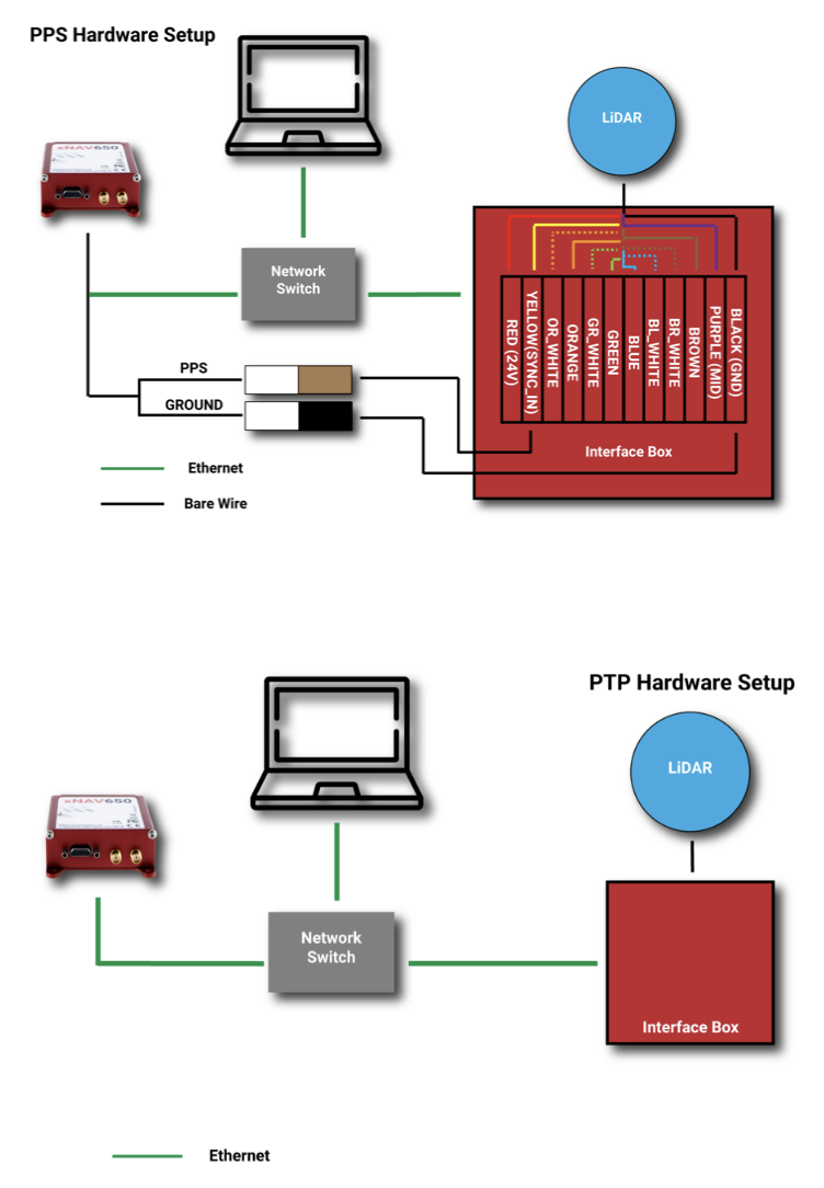
    What keeps the INS and the lidar unit synchronized during a GNSS outage?

    The INS has an internal clock to keep the timing during a GNSS outage. Of course, this will not be as accurate as the atomic clocks on the satellites, but it is quite adequate to maintain survey-grade accuracy during GNSS outages. GNSS is still necessary to get the timing information in the first place, and this is a reliance that INS devices will want to remove in the future.

  • Simplifying the lidar survey requires unity of hardware and software

    Simplifying the lidar survey requires unity of hardware and software

    From OxTS 

    OxTS manufactures inertial navigation systems (INS) and proprietary software on which survey professionals have come to rely. Our devices, the Survey+ and the xNAV650, output highly accurate position, heading and pitch/roll measurements. An advanced navigation engine combines streams of data from onboard inertial measurement units (IMUs) and GNSS receivers. This data can then be used in a multitude of applications including lidar survey, mobile mapping and open road positioning.

    Surveying, especially with a lidar sensor, can be a complicated art. There are many factors to consider even before you begin. However, system manufacturers involved in the survey industry, such as OxTS, are taking steps to simplify lidar survey.

    The end goal for many lidar surveyors is to create an accurate point cloud. However, to produce the best possible results, the hardware and software involved must be working together in unison.

    Hardware = lidar sensor and INS
    Software = georeferencing, post-process and configuration

    In this article, we have picked out a few of our favorite developments on the topic of simplifying lidar survey.

    Research and Development

    OxTS invests substantially in research and development to ensure that our hardware and software developments meet the ever-evolving demands of the survey industry. Many of the improvements generally center around improving accuracy, clarity of results and user experience. However, general industry demands also drive some development.

    For example, the increasing use of drones in surveying has increased demand for smaller and lighter INS hardware. Whilst developing smaller and lighter hardware is therefore important it cannot be to the detriment of reliability and accuracy. The xNAV650 was born from this industry demand.

    Although development of the xNAV650 was primarily driven by the needs of the survey industry (smaller/lighter hardware), other improvements OxTS has made to the software portfolio has focused on improving user experience.

    Photo:xNAV650 and Survey+ inertial navigation systems. (Photo: OxTS)
    xNAV650 and Survey+ inertial navigation systems. (Photo: OxTS)

    Precision Time Protocol (PTP)

    One of the major advances in OxTS INS technology over the past 12 months is PTP. The drive to include PTP capability on all OxTS Survey INS devices was the intention to help surveyors simplify the lidar survey set-up process.

    When using compatible lidar sensors, such as those from Hesai and Ouster with an OxTS INS, surveyors no longer need to build complex wiring solutions. A simple ethernet ‘plug-and-play’ process is all that is required.

    The images below show a traditional PPS wiring set-up vs PTP:

    A traditional PPS wiring set-up vs PTP. (Image: OxTS)
    A traditional PPS wiring set-up vs PTP. (Image: OxTS)

    Software

    To get the desired outcome, an accurate georeferenced point cloud, from any lidar survey in a timely manner the software must be simple and straightforward to use. As the saying goes “complexity is the enemy of execution,” and this is what drives software development at OxTS.

    Once the lidar and INS are plugged in and ready to survey, configuration should be straightforward. A simple configuration wizard, such as the one available in NAVsuite (OxTS’ complimentary software toolbox) should structure the set-up process so that nothing is missed.

    NAVconfig – OxTS’ INS configuration software. (Image: OxTS)
    NAVconfig – OxTS’ INS configuration software. (Image: OxTS)

    The latest NAVsuite update (version 3.3) included a new PTP graphical user interface (GUI) to simplify survey set-up even further.

    Other tools are included within NAVsuite that allow users to analyze, troubleshoot and post-process their INS data. Read the NAVsuite for Survey and Mapping infosheet to find out more about these.

    OxTS Georeferencer

    OxTS Georeferencer. (Image: OxTS)
    OxTS Georeferencer. (Image: OxTS)

    Since its launch approximately two years ago, OxTS Georeferencer has gone through some major changes. The first version included compatibility with the Velodyne VLP-16 lidar sensor. This meant that users of the VLP-16 had a quick and simple way to georeference the lidar data.

    Over the course of the next 24 months, multiple new sensors have been introduced. Sensors from Hesai, Ouster, Livox and new Velodyne devices are now available, giving users more choice than ever before when it comes to choosing the hardware to do their job. Visit the OxTS Georeferencer product page for a complete list of available sensors.

    Furthermore, as well as the integration of new sensors, we have introduced a raft of new features to improve the user experience for professional lidar surveyors. These include:

    • a 3D hardware setup viewer to enable quick and intuitive survey configuration
    • multiple processing options that allow users to view and process only the areas of the point cloud that are of interest therefore minimizing the data size
    • the ability for users to process data in a range of coordinate systems including, local coordinates, ECEF, LLA (latitude, longitude and altitude)
    • processing advances that enable users to process data faster than ever before.

    Data-Driven Boresight Calibration

    One of the most challenging parts of the lidar survey set-up process is aligning the coordinate frames of the lidar and INS devices. Failure to align these with sufficient accuracy can lead to blurring and double-vision in point clouds.

    Many surveyors try to do this by eye, or by developing expensive CAD models, however there is a simpler, quicker and more cost-effective way – using data.

    Built into OxTS’ lidar georeferencing software OxTS Georeferencer, there is an optional boresight calibration tool. It requires the surveyor to survey two static “targets” (see the images below) from multiple distances and angles. The data is then calibrated, and the angle displacement calculated to a tenth of a degree.

    OxTS Georeferencer includes an optional boresight calibration tool. (Photos: OxTS)
    OxTS Georeferencer includes an optional boresight calibration tool. (Photos: OxTS)

    Once the initial boresight calibration has taken place, if the setup is not altered in any way, the coordinate frame alignment will be valid for any future survey.

    The Future

    In the coming weeks and months, the development of new hardware and software features will further streamline the survey process.

  • OxTS announces new xNAV650 post-processed specifications

    OxTS announces new xNAV650 post-processed specifications

    Photo: OxTS
    Photo: OxTS

    In 2021, OxTS released its smallest, lightest and most affordable inertial navigation system (INS) to date — the xNAV650.

    At release, the xNAV650 detailed real-time specifications only. However, after additional testing, OxTS has announced post-processed specifications.

    Photo:

    Because of its small size and low weight, the xNAV650 is suitable for SWaP-constrained applications. It is also used in many mobile-mapping scenarios. Alongside OxTS Georeferencer, measurements created by the xNAV650 can be used to georeference point clouds from multiple lidar sensors.

    By announcing these new specifications, OxTS aims to keep surveyors informed of the performance they can expect from the xNAV650 in both real time and post-processing.

    OxTS has been manufacturing INS for more than 20 years. Their INS are widely used in both the automotive testing and survey and mapping industries.

  • OxTS offers tiny inertial navigation system for drone surveys

    OxTS offers tiny inertial navigation system for drone surveys

    Oxford Technical Solutions has released the xNAV650, the latest in its line of inertial navigation systems (INS), suitable for use on drones.

    INS provide surveyors with absolute position, timing and inertial measurements (heading and pitch/roll) that they can integrate into their survey projects. The measurements, when combined with data from other devices (such as lidar sensors and cameras), can greatly enhance the surveying process, leading to a greater return on investment, according to the company.

    The xNAV650 is OxTS’ smallest, lightest and most affordable INS to date. It combines 20 years of navigation experience with the latest micro-electromechanical (MEMS) inertial measurement unit (IMU) technology and survey-grade GNSS receivers.

    UAV Guidance

    The xNAV650 provides highly accurate and reliable measurements – even when payload size and weight are imperative to consider, including for use with unmanned aerial vehicles (UAVs). It measures 77 x 63 x 24 mm and weighs 130 grams.

    The xNAV650 INS is suitable for a wide range of UAV data-collection applications, including surveys of bridges, buildings, forests and rail; coastal monitoring; map creation and pipeline exploration.

    OxTS’ partner Dronezone used the xNAV650 INS and a Velodyne VLP-16 lidar on a drone to conduct a scan of an aging bridge to look for structural and potential hazards from overgrown foliage.

    By fusing the timing, position and inertial data from the INS with the raw data of the Velodyne VLP-16 (using OxTS’ lidar georeferencing software OxTS Georeferencer), the surveyor was able to produce a highly accurate 3D point cloud of the bridge. Fusing the position and inertial data from the xNAV650 INS with the Velodyne VLP-16 lidar data provides a high level of clarit, which can be seen in the foliage, electricity lines and side of the bridge.

    The resulting point cloud has enabled the engineers to easily and accurately pinpoint areas of the bridge that need closer attention.

    Side view point cloud of bridge. Data collected using and OxTS xNAV650 INS and Velodyne VLP-16 lidar. Data processed using OxTS Georeferencer. (Image: OxTS)
    Side view point cloud of bridge. Data collected using and OxTS xNAV650 INS and Velodyne VLP-16 lidar. Data processed using OxTS Georeferencer. (Image: OxTS)

    NAVsuite Software

    Data from OxTS INS can be fused with the data from almost any lidar sensor. Using OxTS Georeferencer software, point clouds can be georeferences from lidar units specifically from Velodyne, Hesai and Ouster sensors. Work is underway to integrate new lidar sensors from an even wider range of manufacturers into OxTS Georeferencer – allowing OxTS INS users to build a full navigation solution where much of the integration work is already taken care of.

    OxTS NAVsuite software is included with all OxTS INS. The full range of software tools allows users of OxTS’ devices to configure and post-process data with ease.

    Other optional software features are also available, including Precision Time Protocol (PTP) and GX/IX tight-coupling technology. PTP allows for a much simpler lidar survey set-up over ethernet while simultaneously stamping out time-drift by utilizing the high-quality INS clock source – GNSS. GX/IX tight-coupling technology, OxTS’ own proprietary navigation engine, ensures that users of OxTS Inertial Navigation Systems receive the most accurate measurements possible even in tough GNSS conditions.