A link to the live event will be sent to you two hours before the event. Your personalized event URL will be automatically generated by the ON24 system. To ensure receipt of the email, please whitelist this email address by adding it to your contacts: [email protected].
This presentation will begin at 1 p.m. Eastern / 10 a.m. Pacific on Thursday, Oct. 3. A recording will also be sent to you the following day so you can watch it on-demand.
Audience members may arrive 15 minutes prior to live time. If you have any questions, please contact event moderator Bethany Chambers at [email protected].
A link to the live event will be sent to you two hours before the event. Your personalized event URL will be automatically generated by the ON24 system. To ensure receipt of the email, please whitelist this email address by adding it to your contacts: [email protected].
This presentation will begin on at 1 p.m. EDT / 10 a.m. PDT on Thursday, Aug. 22.
Audience members may arrive 15 minutes prior to live time. If you have any questions, please contact event producer Grace Rybak at [email protected].
A link to the live event will be sent to you two hours before the event. Your personalized event URL will be automatically generated by the ON24 system. To ensure receipt of the email, please whitelist this email address by adding it to your contacts: [email protected].
This presentation will begin on at 1 p.m. EDT / 10 a.m. PDT on Thursday, June 15, 2017.
Audience members may arrive 15 minutes prior to live time. You may need to download Flash Player in advance. If you have any questions, please contact event producer Joelle Harms at [email protected].
Integrated with images and dense distance measurements from a range camera using active illumination, inertial navigation produces real-time results on a tablet computer. Experiments demonstrate that the system provides good positioning and mapping performance in a range of indoor environments, including darkness and smoke.
Soldier with prototype system mounted on tactical vest.
Positioning and mapping abilities for indoor environments can speed search and rescue, keep firefighters from getting lost, and help a commander track soldiers searching a building. Accurate results from these environments increase personnel safety in unknown, dangerous environments and can also facilitate remote control of unmanned ground vehicles (UGVs).
A new iteration in the Chameleon family of positioning systems that we have developed, the Tiger Chameleon, combines an inertial measurement unit (IMU) with an active camera that measures distances using modulated laser light. This type of camera provides dense and accurate distance measurements, and has the added advantage of working well in darkness.
The main goal of the Chameleon systems is to provide soldiers and first responders with position information and approximate overview maps, preferably without affecting their operating procedure. The Tiger Chameleon does not require any infrastructure, such as visual markers or radio beacons. Positioning and mapping results are computed in real time based on data from the IMU and the active camera, and wirelessly transmitted to a visualization interface running on a tablet computer or smartphone.
Sensors and Hardware
In initial experiments, the Tiger Chameleon’s components are enclosed in a wooden box which can be mounted on a soldier’s tactical vest. FIGURE 1gives a schematic overview.
FIGURE 1. Schematic overview of how the components are connected.
Image Sensor. The image sensor includes two cameras: one high-resolution visual camera and one lower-resolution depth sensor. The latter uses a modulated near-infrared (NIR) light source and a special type of sensor to measure distance. Essentially, each pixel is divided into two halves, one of which integrates incoming light when the light source is turned on, while the other integrates light when it is turned off. If the light hitting a pixel has bounced off an object located close to the sensor, almost all light will be integrated by the first half of the pixel. If the object is moved further away, it will take longer for the light to return, and hence more light will be integrated by the second half of the pixel.
In addition to measuring the depth of the scene, the NIR camera provides an intensity image where the value of each pixel is determined by the total amount of light hitting the two pixel halves. The intensity image is similar to an ordinary visual image. Unlike an image from a passive camera, however, it is largely independent of ambient light, since it mostly measures reflected light from the illuminator. Hence, both the intensity and the depth images are available even in completely dark or obscured environments. Coming from the same sensor, the intensity and depth images are perfectly registered to each other. Images are produced at 30 Hz.
The high-resolution visual camera is not used by this prototype.
Inertial Sensor. The IMU provides calibrated measurements of acceleration and angular velocity at 400 Hz. The sensor itself does not perform any inertial navigation or attitude estimation. Since we fuse the inertial data with image-based features for navigation, however, the basic acceleration and angular velocity measurements are more useful in our application than pre-filtered position or orientation estimates. The sensor measures acceleration up to 5 g, and angular velocity up to 1,000 degrees/ second, since relatively high-dynamic motion is common in the intended application. The IMU also contains a magnetometer and a barometer, but these are not used since air pressure and magnetic fields are not always reliable for navigation indoors.
Algorithms
The positioning algorithm is based on EKF-SLAM, simultaneous localization and mapping (SLAM) implemented as an extended Kalman filter (EKF). The EKF fuses data from the IMU (three-dimensional accelerations and angular velocities) with image data, according to the uncertainties of the different types of data. It tracks the system state, composed of the position, velocity and orientation of the system, the IMU biases (slowly varying offsets in the acceleration and angular velocity measurements), and the positions of a number of landmarks in the images.
The landmarks are points observed in the images, which are used for navigation. These are chosen to be points which are recognizable, well-defined and stationary. This essentially means that it should be easy to recognize a landmark when it appears in a new image, and that the image coordinates of a landmark should be stable in both the horizontal and vertical directions. Thus, corner points are good candidates for landmarks, while line structures in an image are not. The world coordinates of a landmark should not change over time.
Theoretically, it would be possible to navigate using only IMU data. The system orientation would then be obtained by integrating the angular velocities, while the acceleration (after removing the effect of gravity) would be integrated to obtain the velocity, and double-integrated to obtain the position. Due to the high bias variability and noise of micro-electro-mechanical systems (MEMS) IMUs — the only type sufficiently small, lightweight and inexpensive for use by soldiers or firefighters — this only works for a few seconds before the accumulated error grows to an unacceptable level.
In theory, it would also be possible to navigate using only landmarks extracted from the image sequence. This, however, is also problematic in practice. If the system moves too rapidly, successive images may not share any landmarks at all. Additionally, no landmarks are found in featureless environments. This causes image-only navigation to fail in many realistic scenarios.
By fusing the inertial data with landmark observations, we alleviate most of these problems. While the IMU provides good short-term performance, the image data provides long- term stability. Hence, the IMU can overcome short periods with few or no landmarks, while the image data limits the error growth of the system (assuming that the periods without landmarks are not too long).
FIGURE 2. Overview of the algorithm.
Algorithm Flow. In the data fusion FIGURE 2, potential landmarks are found in an intensity image from the NIR camera, by identifying points that can be well localized. The potential landmarks are found by using an interest-point detector. The visual appearance of a point is represented using the SIFT descriptor. The distance to each potential landmark is determined by using the depth image. Potential landmarks are matched to landmarks that are already tracked by the system, based on a combination of their visual appearance and their coordinates (the spatial distance between the observed points and the predicted image coordinates of the tracked points, and the difference between the predicted and the observed distance to the points).
IMU data is used to predict where tracked points should appear. Pure inertial navigation is relatively accurate in the time interval between successive frames (approximately 30 images per second are processed). Observed points, which match tracked points, are used to update the estimated state (position, velocity and so on). Tracking is started for observed points, which do not match any tracked points unless a predetermined number (30 in the current implementation) of points are already tracked. Points that are tracked but not observed in a number of consecutive image pairs are removed from the point tracker.
Each depth image corresponds to a local point cloud, where points lie on the surfaces of objects in the scene observed by the camera. The intensity of each point can be obtained from the corresponding intensity image. Since the position and orientation of the system are estimated by the SLAM algorithm, these local point clouds can be transformed into a common coordinate system, thereby creating a large point cloud representing the entire environment along the trajectory of the system. This point cloud can either be used as a three dimensional model, or projected onto a horizontal plane for an overview map.
Implementation
To accurately predict where tracked landmarks will appear in a new image, it is important to synchronize the image stream and the inertial data. While the IMU handles this well (it can either trigger, or timestamp the trigger pulse from, a camera), synchronization is potentially difficult when working with consumer hardware such as the the one selected for this prototype. However, while the camera cannot be triggered externally, it does perform internal synchronization between the NIR and the visual cameras, which both run at 30 Hz. (It is unknown to us which camera triggers the other, or if there is a third piece of hardware which triggers both cameras.) Using an oscilloscope, we found that a pulse train at 30 Hz can be accessed at a solder point inside the camera.
This 30 Hz signal is active whenever the camera is powered. It is therefore not possible to synchronize the camera to the IMU using only this signal, since it only indicates that an arbitrary image was acquired at the time of each pulse. To synchronize the sensors, we need to know exactly when each specific image was acquired. Thus, a synchronization pulse, which is only transmitted when image acquisition is enabled, is needed. In addition to the 30-Hz pulse train, a signal that is high only when the cameras are active can also be found inside the camera. We perform a logical AND to combine these signals into the desired synchronization pulse.
We obtain the timestamp of each image from the IMU by connecting the combined synchronization signal to its synchronization input. There is a small delay between the first pulse in the combined signal and the time when the first image is acquired. This was measured by recording inertial data and images while first keeping the system stationary, and then rotating it quickly. Manual inspection of the image sequence and the angular velocities reveals that the delay is approximately 8 intra-frame intervals (0.267 s).
Software. The recording and analysis software are written in C++, and run in real time under Linux. It makes heavy use of multi-threading in order to optimize the computational performance of the algorithms.
The software is divided into two subsystems: one that communicates with the sensors, and one that performs the image analysis and SLAM computations. These subsystems communicate using the Robot Operating System (ROS). There is also a subsystem (or “node” in ROS terminology) for playing back previously recorded data. The playback node publishes the same type of messages as the sensor node, and these nodes can therefore be used interchangeably.
FIGURE 3. Overview of the analysis node. Blue boxes represent threads, while red boxes are queues. Purple boxes are other software components, and the orange and the red/green boxes represent the sensors. Orange, red and green lines represent data from the respective sensors. Black lines represent data based on more than one sensor.
FIGURE 3 shows how data flows through the analysis node. Queues buffer data between the different threads. Incoming images from the recording or playback node are initially put in the image queues for feature extraction. After feature extraction (where the depth image is used to determine the distance to each observed landmark), the resulting image features are stored in the potential landmarks queue. The features are then processed by the EKF-SLAM thread, which also reads from the IMU data queue. The resulting pose estimates (positions and orientations) are sent to the communication module, where they are transmitted to the visualization device. In parallel with this, images are also processed by the rectification and mapping threads, where they are paired with poses from the SLAM algorithm to create map data. The map data is also sent to the communication module. A number of efficient libraries exist for low-level image processing, and also for the linear algebra computations needed by the EKF. The following libraries are used:
VLFeat for finding landmarks and extracting SIFT features
OpenCV for image rectification
Armadillo for high-level math operations
ROS for communication between the subsystems
A modified version of IAI Kinect2 for ROS communication with the sensor
A slightly modified version of Libfreenect for low-level communication with the sensor.
Evaluation
The prototype has been evaluated in a number of experiments, in cooperation with soldiers and first responders. Three experiments are reported here. All were performed during soldier or smoke-diver training. Mapping results in the figures are presented along with estimated soldier and smoke-diver trajectories (bluegreen lines) from the positioning system. The results are evaluated based on the mapping, since the ground truth trajectories are unknown. Positioning is still evaluated implicitly, as inaccurate positioning would cause poor mapping performance such as double or skewed walls, since the mapping is based on estimated camera positions and orientations.
Searching for Biological Hazards. Collection of evidence at a crime scene is commonly performed using a camera, taking numerous pictures of the scene from different positions at different angles and distances. To keep track of all images and where they were captured is cumbersome work, which can easily be automated by integrating the camera with a positioning system.
Several variations of this experiment were performed, all in cooperation with soldiers from the Swedish Armed Forces National CBRN Defence Centre. The main task was to document different areas in the building, to be able to handle any encountered dangerous biological objects in a safe way, and to preserve evidence for later use. If a dangerous object is found, the mapping result from the system could be used to plan how the object should be taken care of and what exit path the soldiers could use to minimize the time being exposed to a dangerous environment.
FIGURE 4. Map estimated by the prototype positioning and mapping system while two soldiers searched for biological hazards. The trajectory is also shown. The grid spacing is two meters.
The photo above an image from the NIR sensor in the prototype system, captured in the building while two soldiers searched for biological hazards. A map estimated by the prototype system appears in FIGURE 4.
For evaluation of the mapping performance, a part of this building was also measured using a highly accurate scanning laser system. FIGURE 5 shows the point clouds from both the Tiger Chameleon (black) and the scanning laser (white). Locally (within a room), the errors are less than 5 centimeters. Over larger distances, heading drift causes larger errors, which are visible as slightly misaligned walls. In this case, there are no significant errors. (The structures that are only visible in the laser scanner data are parts of the ceiling and its supporting beams, which were never observed by the positioning system.)
FIGURE 5. Map produced by the Tiger Chameleon (black) overlaid on reference data (white).
Searching a Building. A group of eight soldiers searched and cleared a part of a building. This required them to move more quickly than in the first experiment, since the building could not be assumed to be safe. Additionally, one or several soldiers often appears in the field of view of the positioning system. We requested the soldier carrying the system to avoid walking too close behind another soldier, to avoid covering the entire field of view. Apart from this, the soldiers were asked to act as they normally would during the exercise.
FIGURE 6 Map estimated while eight soldiers cleared a building.
Positioning and mapping results are shown in FIGURE 6. The map is slightly distorted due to errors in the estimated heading, but still good enough to understand the building layout. The distortion is visible as double walls in the top part of the figure. We believe that most of the errors were caused by the system not being entirely stationary during the sensor initialization at the start of the experiment. No reference map is available for this location. We also performed experiments where the soldiers fired their weapons near the positioning system. This affects the IMU, severely degrading the measurements of acceleration and angular velocity. Hence, the positioning system was not able to present correct position or mapping estimates in these cases.
Smoke-Diver Searching a Building. The smoke-diver experiments indicated how the positioning system performs when used in a smoke-filled environment. During the experiments, the system was exposed to different levels of smoke.
FIGURE 7. Map estimated while a smoke-diver searched a (partly) smoke-filled building. The trajectory is also shown.
Positioning and mapping results from the experiment are shown in FIGURE 7, while FIGURE 8shows the result from the Tiger Chameleon (black) overlaid on reference data from the laser scanner (white). The estimated map is in good agreement with the reference map data, although a heading error affects some walls (bottom right).
All smoke densities affect the image quality from the NIR sensor, since the active illumination is reflected by the smoke particles. In light smoke, the main effect is that the smoke appears as spurious points in the point clouds, eventually ending up in the map, while positioning performance is not significantly affected. Most spurious points were removed by adding the constraint that points very close to the camera are not added to the map, although smoke still causes more interior points to be visible in Figure 7 than in the other maps. The effect on the positioning system increases with the smoke density. In thick smoke, most illumination is reflected, effectively rendering positioning impossible using this type of image sensor.
Discussion
FIGURE 8. Maps from the experiment in smoke. The map produced by the Tiger Chameleon (black) is overlaid on reference data (white).
The current positioning algorithm works well, but over longer experiments its position estimate slowly drifts away from the true position. This is caused by both the inertial sensors and the landmark-based positioning updating the current position estimate only relative to recent estimates. Since landmarks are discarded after not being observed for a short time, no loop closures ever occur. Saving landmarks could solve this in specific scenarios, where landmarks are re-observed after long times, but doing so would increase the computational complexity considerably. Additionally, for landmark-based loop closure to work well, the landmarks would need to be reobserved from approximately the same position, further limiting the scenarios where this could be expected to work well. Ongoing work aims instead at closing loops by recognizing the scene geometry, as represented by the point-cloud models.
When using active illumination, the mapping performance does not depend on texture on walls and other surfaces. This is an advantage compared to passive stereo cameras. Further, active illumination enables positioning and mapping in darkness.
Comparison to Other Systems. The prototype system was not constructed with the purpose of creating high accuracy models of small, detailed environments. Rather, the purpose was to enable soldiers to create approximate maps of entire buildings with minimal impact on their operating procedure. Detailed reconstruction is handled better by other systems, but these have the disadvantage of requiring the user to survey the environment systematically, adapting his or her work methods to the sensor.
SWaP-C and Hardware. Size, weight, power and cost (SWaP-C) are constant issues for soldier equipment. Ideally, the equipment should be disposable: cheap enough to throw away after being used just once, or fit into some type of disposable container.
Since this is a prototype system built for research and demonstration purposes, components with convenient electrical and programming interfaces have been selected. Therefore, the system is considerably larger than a final end-user product would be. In such a product, sensors and computation hardware with similar performance, but considerable smaller size, lower weight and lower power consumption, would be selected instead. Such components are commercially available.
Outdoor/Indoor Use. Though this positioning system is primarily designed for indoor use, seamless transition between indoor and outdoor environments is desired. Ongoing work aims at integrating a GPS receiver to achieve this. Adding GPS would also enable positioning in a georeferenced coordinate system; currently, all results are presented in a local coordinate system defined by the start position and orientation. This requires an algorithm for making robust decisions regarding when GPS measurements should be considered reliable.
Visualization Interface. The visualization interface currently runs on a tablet computer, and is therefore most useful to a commander or group leader who remotely tracks the soldier or firefighter. By adapting the interface to the smaller screen of a smartphone, it would be possible to also give the user access to position and map information.
An important advantage of automatic mapping, according to several users, is the ability to detect hidden spaces in buildings. In certain types of operations, the ability to document a building before leaving it is also considered valuable.
Real-Time Implementation. An interesting aspect of performing all computations in real time is that it effectively precludes tuning of algorithm parameters to individual data sets. When analyzing data offline, this is far too common, and typically overestimates the performance of the system or algorithms. All experiments reported in this article have been performed without any such parameter tuning.
Autonomous or Remote-Controlled Platforms. The system can also be used on an unmanned ground or
aerial vehicle (UGV or UAV). This could be suitable for searching buildings too dangerous to enter. The system would continuously distribute its position and mapping estimates while traveling through the building. This could provide soldiers and rescue teams with a preview of the unknown environment and a possibility to plan their operations in a safer way. Many robotics projects use ROS, which makes integration of the Tiger Chameleon relatively straightforward.
Firing of Weapons. During some experiments, we discovered that the measures of acceleration and angular velocity are affected by close-range gunfire. Relatively long segments of measurements are affected, which makes interpolation of missing values difficult. During these periods, it may be possible to disregard the inertial measurements, resorting to only image-based positioning.
Summary
This prototype system for indoor positioning and mapping, based on inertial navigation and distance measurements using active illumination, does not require any infrastructure or prior knowledge about the environment. The system has been designed for experiments and demonstration purposes, and has been shown to provide good performance in real time in a variety of different indoor environments when carried by potential end users.
Manufacturers
The Tiger Chameleon consists of a Microsoft Kinect v2, an Xsens MTi-10 IMU and a small computer with a mobile Intel i7 CPU.
Acknowledgments
The authors thank the soldiers from South Scania Regiment (P7), Sweden, who participated in the initial tests with the prototype. We also thank the smoke divers from Södertörn Fire Prevention Association, Sweden, for carrying the prototype in smoke-filled environments. Also, we really appreciated the feedback from the Swedish Armed Forces National CBRN Defence Centre during the prototype development. Finally, we acknowledge Hannes Ovrén at Linköping University, Sweden, for improving the Libfreenect library.
The material in this article is based on a technical paper presented at ION/IEEE PLANS 2016.
Azuga’s Fleet Driver Rewards App Wins CTIA E-Tech Award
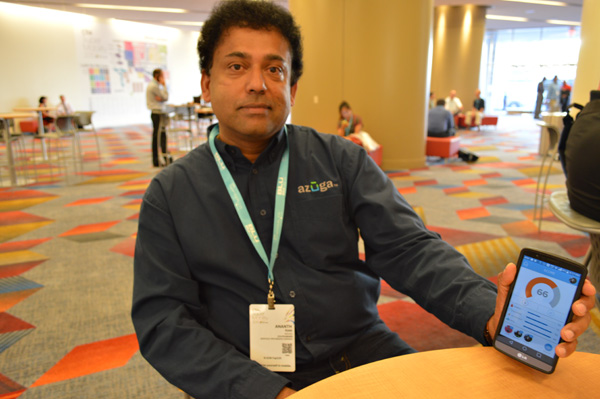
Ananth Rani founded Azuga in 2013.
When Ananth Rani began work in 2012 on the Fleet Driver Rewards app that has made connected vehicle provider Azuga a CTIA up-and-comer, he wasn’t sure he was making the right decision.
“Frankly, it was a bit of an experience to see if there was still room in the market for another vendor,” he said recently as he took time to sit-down at a coffee shop in Las Vegas’ Sands Expo Center amid CTIA Super Mobility 2015. “I thought, ‘What the hell am I getting myself into?’”
The gamble paid off for the Azuga and its dedicated co-founder. Azuga’s app took home second place in the Mobile Cloud division at the CTIA E-Tech Awards Thursday. The honors go to what CTIA describes as “the most innovative emerging mobile services, solutions and technology from areas such as the cloud, network equipment, M2M and the Internet of Things.”
What makes Azuga’s app innovative says Rani, is that it appeals to a unique user: The fleet driver.
Not just managers. Not just owners. The drivers themselves.
“Azuga is all about social telematics,” he says. “It comes from the heart. I tell fleet managers, ‘Do you want to be remembered as a gotcha guy or an attaboy?’”
A Silicon Valley veteran, Rani utilized a principal more likely to be seen in apps marketed to consumers: gamification. Fleet drivers earn points based on things like hard-braking, acceleration, sustained high speeds and driving in adverse weather conditions, among other metrics determined by a Ph.D. in statistics that Azuga has on staff.
“The expectation was that a driver will naturally move toward a safer fleet by competing with the rest of the drivers, and that as the risk goes down the miles per gallon goes up,” Rani said, “and that’s your ROI.”
The reward for winning is no simple badge: Drivers’ profiles are pulled from LinkedIn and their rankings are visible among the “Azuga Awesome Drivers” group on the social network. Rani says Azuga is “not J.D. Power” but aspires to have the same reputation for determining safe drivers.
Azuga Fleet Driver Rewards can gift a reward as a donation to groups like World of Children.
There’s also cash on the line. The company gives out quarterly prizes to the Top 10 drivers and Top 10 fleet managers of the 50,000 nationwide users, and the 1,000+ corporate customers can then also choose to award their drivers based on their own goals through an electronic gift card program that is tied to 14 national brands, including Amazon, Wal-Mart, Home Depot and Burger King. The driver sees the amount awarded and then has the choice of gift cards. Azuga has also recently added three charities to which the drivers can pass the reward as a donation.
Safety and savings aside, employee retention is an additional
“This is a blue collar world where the employee takes the truck home at night. Feeling engaged is the key to employee retention in a world where they may never see the boss and where they only see their manager for a meeting every few weeks.”
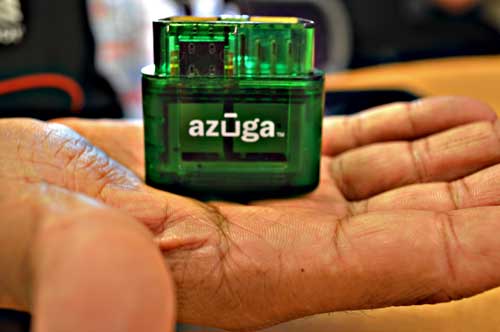
Azuga’s OBD-II connector is manufactured by parent company Danlaw Inc.
Azuga pairs with hardware manufactured by its parent company, Michigan-based Danlaw Inc. Rani sees the relationship as one that benefits Azuga with the “automotive grade DNA” and calls it “Silicon Valley meets Detroit.”
Azuga Fleet costs 69 cents per day per vehicle, and customers are companies of varying sizes with Aaron’s, the rental furniture and home appliances chain, using it for 3,000 trucks and 6,000 drivers on the large end and single-driver landscape companies at the small end.
Growth plans for the app including functions to help drivers find parking, locate a parked truck and easily message clients that they are on their way. The app is also being reviewed by state governments as a tool to determine whose cars need to be emissions-tested and to track hours required for state graduated driver licensing.
It’s currently being tested by the Oregon Department of Transportation as a way to assign a road usage charge that funds highway repairs. The topic is politically divisive, with opponents saying replacing the gas tax with a per-mile fee is inequitable and subsidizes gas-guzzlers and advocates saying it will lead to safer roads and is an easier, faster alternative to tolls. The din doesn’t concern Rani. He says the intent is the same that inspired the fleet management app.
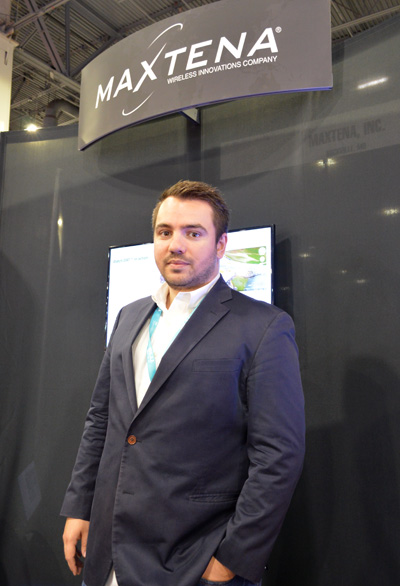
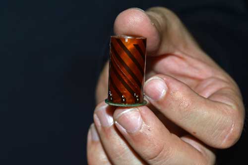
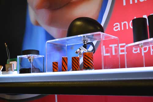
Exhibiting at CTIA Super Mobility 2015, Vanja Maric, director of sales and marketing for Rockville, Maryland-based antenna-maker Maxtena, pointed out the challenge that exists for antenna makers in an uncertain drone market: forecasting what will happen next and planning for that future.
“The problem with the drone space its so volatile and so fragmented, and it’s very, very hard to predict,” Maric said. “Speaking to industry leaders in the UAV market, they don’t even know what it’s going to be in three years, and it’s very hard to put all your cards in that.”
That fragmentation is largely a dichotomy between the needs of the professional-grade market and the recreational drone pilots, Maric said. Maxtena is currently the antenna provider for several large UAV manufacturers, although confidentiality prevents them from being named.
“It all comes down to the necessity of precision, and different industries have different needs. UAVs, for example, some use very simple GPS patch antennas, simple receivers and precise location is not as important,” he said. “Then you have guys in the professional space where it is a necessity.”
That necessity right now is in the survey market, particularly RTK solutions for construction and mining operations in emerging countries. The company has seen an uptick in customers from Asia looking for antennas for Beidou. More specifically, Maric said handhelds for lone worker tracking in open pit mining in China has had “fantastic” growth. The M1227 antenna released earlier this year accomplishes this goal.
Maxtena GPS antennas at CTIA 2015
“It’s not just hardware; they have a lot of costs—software, mapping— in on all that, and if that package is right, you have something special. However, don’t forget: The antenna is the link between you and the satellite. That antenna has to be right; that’s what most companies forget,” Maric said. “You can have the best receivers and software in the world, but if you can’t make the link you can’t do it.”
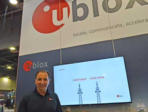
Carrier-independent LTE modules, the autonomous vehicle and delivery drones all factor into future plans for the Swiss wireless company
Nick Papadopoulos
What’s new from u-blox?
There’s a ton of new things. One is that we are now expanding our portfolio into short-range radio, meaning we have now products that are Bluetooth- and Wi-Fi-capable, which is useful especially in the automotive industries.
And on another note, on the cellular side which we have been shipping since 2010, we have now introduced one a high-speed LTE module that is carrier independent in the United States so it can do both AT&T and Verizon at the same time so customers have the option as part of their logistics chain to build their product and not have to worry if this is an AT&T module now or a Verizon module. It simplifies logistics, simplifies the entire manufacturing chain and reduces cost.
What are some use cases for the carrier-independent module?
One of our customers builds devices—whether for alarm panels, tracking devices, telematics devices—where at the time of manufacture in the past they would actually have to determine for which carrier this particular device is going to made. So imagine the warehouse where they have to have one shelf for AT&T devices and another shelf for Verizon devices. It duplicates the effort. It costs money to have this kind of inventory, and you don’t know when you manufacture how many AT&T devices am I going to sell how many Verizon devices am I going to sell. That goes away. The same goes with tablets.
This is for the automotive market as well?
Imagine a carmaker who actually has a telematics control unit and they have an agreement say with one of the carriers—I’m not saying which—and two years down the road they have 8 million vehicles with telematics unit and then after two years decides the rates I’m getting with Carrier A, I could get better rates from Carrier B, so going forward they now sell vehicles car with telematics units with Carrier B. But everything they’ve sold in the past two years is still relying on Carrier A and, with the data buckets they have to pay still with that carrier, they don’t have any cost advantage there only moving forward. Now with our modem they can actually switch the entire base to Carrier B and save on the cost.
Can you tell us with whom you are working on this?
We are working with several customers on this and have a designed product, but I cannot tell you at this point until they allow us to—we’re working with them so it’s probably going to be the beginning of next year (before an announcement is made).
What do you think it is that is giving your automotive innovations longevity?
One of the things we have been working on is the development of our own LTE chipset and that has advantages–for one cost advantages—because LTE-only technology does not compete with our partners and so far that actually allows us to develop new products, new modules based on our own LTE chipset and expands our portfolio especially in North America where we hope in the next few years LTE will be so prevalent you won’t need any 2G or 3G, so that’s one of the things.
We have also announced we are working very closely on the positioning side with several carmakers toward technology for autonomous vehicles. We’ve revolutionized positioning technology to the point you can identify which altitude you’re at in a parking garage. That is expanding to allow additional accuracy in very adverse environments for preparation of so called ADAS systems toward autonomous vehicles.
What can we expect from this technology in the next few years?
You have already today cars that park themselves. You have already today cars that are autonomous, but there are still passengers there just to monitor. A lot of the technology that already there is actually based on our dead reckoning technology. We are expanding around that in order to eventually truly allow autonomous vehicles to the point where those vehicles can actually park themselves in a valet scenario.
Imagine driving up to a hotel and telling your car to go park yourself and it does it. It knows where to go and it eventually finds a spot and it parks itself without endangering anyone, and it can do that due to our technology, even underground. I do see in the next three-to-four years several carmakers launching vehicles that can drive autonomously on the highway. And they will need our technology for it.
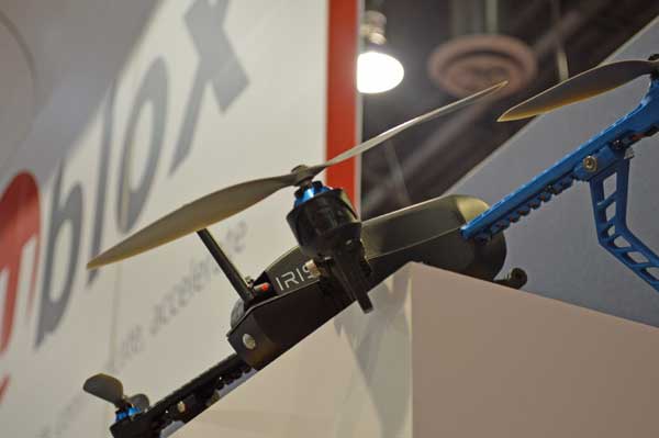
The IRIS+ drone utilizes the u-blox GPS module.
What about usage in UAVs?
We are the leader in positioning technology for drones. We’re developing the technology to further improve position accuracy for delivery drones. So not just for recreational use but truly for professional utilization either for delivery, package delivery, agricultural delivery, pesticide/herbicide delivery. You need very, very accurate positioning technology.
Where do you see the UAV industry going?
I see consolidation eventually but at the same time, I see more and more proliferation of companies developing new types of drones.
What’s the key to u-blox’s success?
We have been phenomenally lucky that we have such good customers, who are not only loyal to us, but they spread the word and they bring more customers. I am very thankful and grateful to our customers and colleagues.
With market share second only to Ericsson, TeleCommunication Systems Inc. (TCS) is investing in location-based services (LBS), particularly those used for indoor location.
One key investment was the July acquisition of Loctronix, a small Seattle-based provider of positioning systems for GNSS-challenged environments.
TCS senior vice president and commercial software group president Jay Whitehurst spoke exclusively to GPS World at CTIA Super Mobility 2015 in Las Vegas this week about the acquisition.
“We’ve been building out the (indoor location) technology, and we bought the assets of Loctronix and hired their CEO (Michael B. Mathews),” Whitehurst said. “They had a developed library and were at proof-of-concept almost ready to go to market and needed a vehicle to get it out there. We have 50 percent market share in E911, and in LBS we have 26 percent market share, relative to Ericsson’s 28 percent.”
Loctronix’s Mobile Explorer Platform is designed for mobile devices, and delivers high-accuracy positioning booth indoors and out.
The acquisition comes as TCS completes E911 interoperability testing with four public-safety equipment vendors, ahead of impending government regulation of E911 and with increasing public awareness about the need for emergency services that work with modern technology.
Beyond public safety and security, Whitehurst says there are “unlimited applications” for the company’s indoor location tools in the commercial sector.
From Mathews’ perspective, he made “the right choice” in selling his company. Mathews is now vice president of location technology at TCS.
“I found it was easy to be an evangelist, but scaling that into a commercial solution you could sell and make money on are two very different things. It’s easy to have vision, but you’ve got to have infrastructure and the scale of a company behind you to get it to happen,” he said, standing next to Whitehurst in the TCS booth. “We were able to fit into their infrastructure, and they’ve got a lot of tools we couldn’t wait to get our hands on.”
TCS plans to announce new geolocation tools based on the Loctronix assets in the fourth quarter. Without going into detail, Mathews described what’s coming as a “holistic solution” — then joked with Whitehurst that in his new role as a “tech guy” instead of CEO, “It’s not my problem.”
“The story we’re going to tell the next few months is pretty awesome,” Mathews said. “When we say location everywhere we mean location everywhere.”
Whitehurst presents VirtuMedix, a telemedicine platform using TCS’s LBS solutions
“In the healthcare market vertical, clinicians are licensed to practice in a state. So knowing when somebody is accessing a healthcare provider by a mobile device, we have to determine if they are in the state the clinician is licensed to practice. It’s an important usage of (location-based services).”
PodsystemM2M, which specializes in multi-network data solutions for the M2M and Internet of Things (IoT) industries, announced a new partnership program for providers of M2M and IoT hardware and software that aims to fast track solutions to market by providing tried and tested components for companies looking to develop end-to-end solutions. The announcement was made at CTIA Super Mobility 2015, held in Las Vegas Sept. 8-11.
The program has the support of software solutions providers Gurtam, Betaar3 and Gosafe, who provide hardware for fleet management solutions. The aim is to create a community in each sector enabling developers to choose the best components for their product and get advice from M2M experts. The first sector covered is GPS tracking for fleet management and logistics.
Gurtam provides a powerful fleet intelligence software platform called Wialon, which allows GPS tracking solution companies to deliver a feature-rich and cost-effective service to end-user fleets globally. The platform is used by more than 650 solution providers on five continents.
Betaar3 is a global provider of mobile workforce solutions for service-based businesses of all sizes delivered as software-as-a-service (SaaS).
Gosafe develops and distributes GPS fleet management products including hardware and software solutions that utilize existing wireless network infrastructures to provide web-based vertical applications to commercial customers as well as consumers. Gosafe’s products are sold in more than 100 countries.
“We are excited to partner with Podsystem and be in a position to recommend them as a connectivity provider with an excellent track record for reliable service and outstanding customer experience,” Gurtam Managing Director Sergei Leuchanka said in a press release. “Choices for connectivity are vast, but not many providers can boast the same level of staff dedication and technical capabilities that many of our customers in North America have come to expect from Podsystem.”
It wasn’t enough for AT&T Mobility President & CEO Glenn Lurie to make just one major announcement during his keynote address at CTIA Super Mobility 2015 Thursday.
He had to make several.
Most significantly, AT&T used the stage in front of a packed crowd, including their biggest competitors, to introduce new personal security, fleet tracking and connected car solutions.
On the personal security front, Lurie announced the Digital Life Personal Security app, essentially a panic button for your smartphone that’s fully monitored and connected to emergency services much like home security and automation components of the Digital Life portfolio. The innovation came from customer feedback that “Digital Life is terrific, but you can’t take it with you.”
Lurie said this technology was personal to him as the father of a 19-year-old daughter.
“Imagine the opportunity of a 24/7 monitoring facility taking care of her, the ability for her to hit a button and instantly know where she is and instantly have the police come,” he said. “We’re going to offer to digital life customers and offer to anybody who wants to add this to their smartphone.”
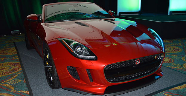
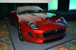
AT&T also announced major collaborations with connected vehicle technology provider Telogis and automaker Jaguar Land Rover North America. Telogis’ software-as-a-service-based telematics software will allow AT&T to offer full-fleet solutions for business. Telogis is already the commercial vehicle telematics provider used by Ford, General Motors, Volvo, Mack and Isuzu. Meanwhile The AT&T service management platform allows Telogis to “manage the data, devices and services that support its customers,” according to a press release on the AT&T and Telogis announcement.
AT&T Mobility CEO Glenn Lurie thanks CTIA CEO Meredith Atwell-Baker for the association’s support.
New Jaguar and Land Rover models will be equipped with AT&T Wi-Fi and infotainment systems.
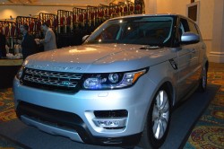
New Range Rover models already feature AT&T connectivity.
With Jaguar and Land Rover, AT&T connectivity will power the infotainment features, including Wi-Fi hotspot, navigation and apps. AT&T had already begun equipping Range Rover models with the technology earlier this month; this announcement is an expansion of that to other Jaguar and Land Rover models, which will come later this year. AT&T customers will be able to share one data plan for their smartphone and car with a Mobile Share Value plan, which is $10 per month.
“We view the connected car as the next great device in your life,” said Lurie, who also gave a keynote at last year’s CTIA conference. “About half of the cars this year will be connected by AT&T.”
TeleCommunication Systems Inc. (TCS) announced at CTIA today that by year’s end the company will offer Network Functions Virtualization (NFV) for all of its technology solutions for location-based services (LBS) and messaging. Integrating NFV enables TCS customers, including global wireless operators and enterprises, to virtualize entire classes of network node functions into communication services that will cost-effectively run on common off-the-shelf, non-proprietary hardware platforms.
The new architecture is expected to enable customers to build specific and individualized networks that address their changing needs, and reduce time to market for new functionality and features. The solution can be deployed using a cloud-based, low-cost data center environment for both messaging and location solutions.
“By migrating all of our best-in-class solutions to NFV, we will be able to make our software available at any time and on non-proprietary platforms, reducing costs and complexity. This flexibility and agility will reduce customer costs, both CapEx and OpEx,” TCS Commercial Software Group President Jay Whitehurst said in a statement. “Virtualizing our location-based and messaging platforms is a critical expansion vector for TCS as we can now serve a larger set of customers in a more cost-effective manner.”
In a press release, TCS quoted a study by ABI Research saying it is the global leader in precise LBS infrastructure. TCS offers time-tested, end-to-end, LBS solutions that include applications, infrastructure, mapping, and content, processing more than 7 billion LBS transactions monthly.
TCS, based in Annapolis, Md., is a world leader in secure and highly reliable wireless communications. for E911, commercial LBS, cybersecurity, defense and more.
VP says company remains “bullish”on in-car Wi-Fi, sees need for both embedded, bring-your-own-device solutions
Mercedes-Benz has been in the news in the past month for offering connected car service as standard for five years on all new vehicles, one of the longest multi-year offers yet. But it isn’t just big news for Mercedes; it’s also a testament to Verizon’s continued investment in connected car technology.
Verizon is one of the longest tenured telematics providers in the U.S. market and has worked with Mercedes-Benz since 2009, said Mike Peterson, vice president and general manager of OEM business for Verizon Telematics, in an exclusive interview with GPS World.
“Mbrace has the widest breadth of services, including remote connection for door lock/unlock, remote vehicle start, a feature that consumers have been asking for for a long time as evidenced by after-market industry,” Peterson said. “We’re also delivering diagnostics data to dealers and adding the ability to access certain apps on the head unit without the user tethering their phone — that’s the big new thing.”
Verizon is exhibiting mbrace at CTIA Super Mobility 2015 in Las Vegas this week. mbrace services include navigation, location apps, remote safety and security features, and advanced travel assistance.
Embedded connectivity is a more expensive alternative to the bring-your-own-device (BYOD) model. Despite the embedded vs. BYOD debate in the industry at-large, Peterson doesn’t see one way as better than the other.
“Part of it is always demographics. With Mercedes-Benz customers, while the majority are connected with smartphones, the simplicity of having to use a radio head unit as opposed to their phones will be the right experience to create for premium customers,” Peterson explained. “Other price sensitive brands will continue to see BYOD as the way to go.”
Peterson admits the decision to equip all vehicles with the service is in part designed to prime customers so that the technology becomes a must-have. But, he adds, that the connected car creates a relationship between the manufacturer and consumer that benefits both, particularly with regard to safety.
While Verizon is the telematics provider to six OEMs in the U.S., including Volkswagon and Hyundai, Peterson doesn’t take the credit for decisions like the one Mercedes made when extending mbrace’s reach.
“I would call it a partnership heavily influenced by automakers. At the end of the day, the automaker decides what equipment to put into their vehicles. We provide all service, but they very much protect what goes into their car.”
One feature of mbrace that Peterson calls “a big deal” is the ability to turn your vehicle into a Wi-Fi hotspot. It’s a feature that has gotten caught between customer demands and regulator concerns that those increased demands will lead to spectrum-sharing that hampers the progress of vehicle-to-vehicle (V2V) communications.
“We are quite bullish on Wi-Fi in the car. You’re already equipping the vehicle with a connected device that’s Wi-Fi capable,” Peterson said. “We’ve done considerable research, and it’s all come back very positive.”