Anritsu Corporation and Orolia announce immediate support of assisted GPS (A-GPS) test functionality to meet 5G New Radio (NR) Carrier Acceptance Testing (CAT) requirements for multiple North American operators on the Anritsu ME7834NR 5G mobile device test platform.
As part of the strategic partnership between the two companies, Anritsu leverages Orolia’s GNSS simulation capabilities to deliver A-GPS CAT testing platforms featuring the new Orolia GSG-SKY-ANR solution. The Anritsu MR7834NR supports A-GPS, FR1, FR2, FR1+FR2 NSA and SA US operator signaling requirements on the same platform.
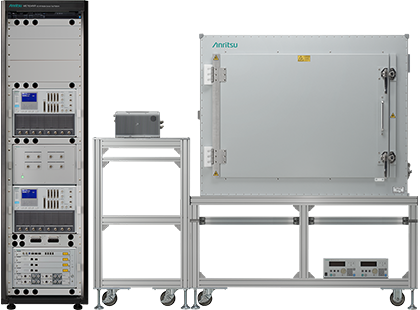
The ME7834NR 5G NR mobile device test platform. (Photo: Anritsu)
The A-GPS simulation component of Anritsu’s ME7834NR-based test solution leverages Orolia’s GSG-SKY-ANR simulation platform. The GSG-SKY-ANR is powered by Orolia’s award-winning SKYDEL simulation engine, which delivers flexible, scalable, and efficient GNSS/GPS simulation solutions. The GSG-SKY-ANR GNSS simulator is exclusively available to Anritsu ME7834NR customers.
Anritsu ME7834NR A-GPS-enabled solutions for 5G NR CAT requirements are available immediately. The test solutions support the rollout of nationwide 5G networks by helping to ensure device compliance and optimum operability.
“Anritsu continues to address the needs of our customers globally,” said Shinya Ajiro, general manager of Anritsu Corporation. “By partnering with Orolia, a worldwide leader in GPS simulation technology, we are introducing a reliable, accurate, and cost-effective A-GPS CAT solution that conforms to operator requirements and delivers repeatable results. We remain committed to provide the validation tools necessary for mobile operators, device makers, chipset manufacturers, and test houses to verify designs and ensure product performance. This benefits everyone in the mobile ecosystem.”
“Orolia is proud to support North American operators through our partnership with Anritsu,” said Lisa Perdue, simulation director at Orolia. “Our resilient GPS simulation solutions deliver proven high-end capabilities for critical technology challenges such as the implementation of 5G.”
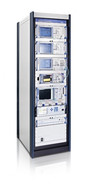
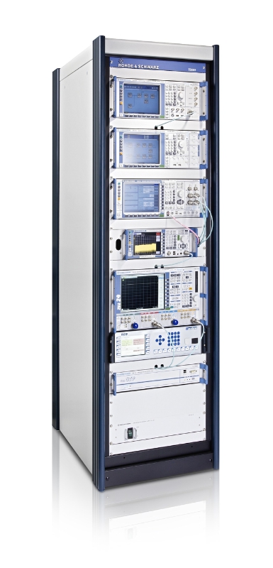
R&S TS8991 Wireless Performance Test Chamber.(PRNewsFoto/Rohde & Schwarz)
PCTEST Engineering Laboratory, an accredited testing laboratory for wireless testing and certification, has expanded its over-the-air (OTA) conformance testing capabilities with the purchase of a CTIA-compliant R&S TS8991 Wireless Performance Test Chamber (WPTC) from Rohde & Schwarz.
The R&S TS8991 OTA Test System is configured with hardware and software extensions for legacy and LTE A-GPS, a R&S ZND vector network analyzer for passive antenna measurements and faster system calibrations, and a second antenna boom with additional R&S NRP power sensors for faster total radiated power (TRP) measurements. The entire system is controlled via R&S AMS32 wireless performance software.
As the number of technologies and the variety of mobile devices continue to increase, the ability to verify a device’s radiated performance is becoming more important to ensure end-user quality of experience. For 4G/LTE, there are major developments involving the Internet of Things, machine-to-machine communication, LTE at 5GHz (LTE-U), assisted global navigation satellite system (A-GNSS), and carrier aggregation, which are driving the need for improved as well as additional OTA tests required for both carrier acceptance and industry conformance test plans.
“As wireless devices become more specialized and continue to push the boundaries of transmission efficiency, the ability to fully characterize a device in an over-the-air environment is becoming more critical,” said Randy Ortanez, president of PCTEST Lab. “Every day we are seeing the acceptance bar being raised and more test cases defined from operators and standard bodies such as CTIA and 3GPP. To meet these growing demands, we are very pleased to be working with our partner Rohde & Schwarz who is able to deliver and support a complete turn-key solution for our OTA testing needs.”
PCTEST is exhibiting in the Test Pavilion of Hall C, Booth 5159, at the CTIA Super Mobility trade show, taking place this week at the Sands EXPO in Las Vegas. Rohde & Schwarz is exhibiting in Booth 3249.
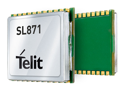
Telit Wireless Solutions has debuted the Jupiter SL871-S, designed for easy migration between a full-GNSS solution for top-ranked applications and a simple GPS-only solution for less demanding applications. The Jupiter SL871-S is designed to track and navigate GPS and QZSS constellations while ensuring pin-to-pin and protocol compatibility with its multi-constellation companion module, the SL871.
The module comes in a 9.7 x 10.1 millimeter LCC package with an ARM7 baseband processor, embedded ROM memory, and integrated LNA. It delivers geolocation data using NMEA protocol through a standard UART port. It supports ephemeris file injection (A-GPS) as well as Satellite Based Augmentation System (SBAS) for increased position accuracy.
In addition, its extremely low power consumption in all conditions is suited to applications requiring long battery life.
SL871-S has been designed to ensure hardware and software compatibility with SL871, allowing customers to design once and take advantage of the xL871 common form factor. Benefits include:
Pin-to-pin compatibility with SL871 family,
Same protocol used in SL871,
Straightforward migration between full-GNSS solutions and GPS-only solutions,
Satellite Based Augmentation System (SBAS) support for increased position accuracy, and
Assisted GPS.
The SL871-S can replace the SL871, allowing customers to design once and interchangeably mount the appropriate solution depending on the required features.
“The new SL871-S module designed to be easily swapped with other xL871 modules for enhanced simplicity and scalability,” said Taneli Tuurnala, CEO of Telit GNSS Solutions. “It is an ideal example of how buying a module from Telit enables our customers to avert the need to keep track of the latest chipset technology on their own. We keep them on top of the best available technology, pre-packaged in a module that is easy to replace as needed, without having to redesign their entire application to stay up to date.”
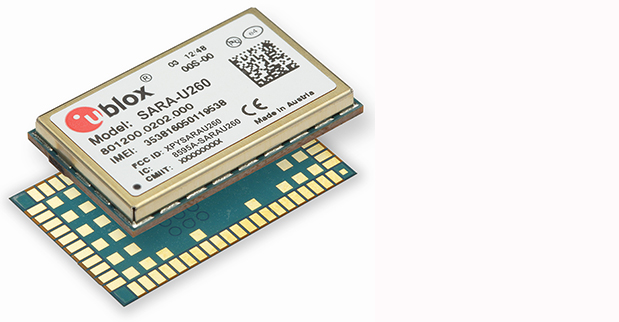
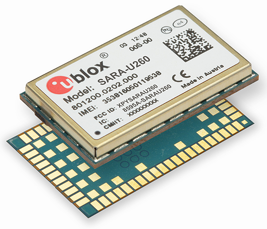
Swiss u‑blox says that its SARA-U260 dual-band 3G/2G module has achieved AT&T network compatible status.
The certification allows customers to design SARA-U260 modems into M2M devices operating over AT&T’s extensive 3G network in the USA. Typical applications include small tracking boxes, usage-based insurance devices, smart metering, wearable electronics, and connected fitness watches.
SARA-U260 is a complete 3G/2G voice/data module for applications that still require roaming ability with 2G using AT&T’s extensive 3G network coverage. The SARA-U260 provides full voice and data capability as well as a full suite of IP protocol stacks. The module features have been selected to give customers specific features they need for telematics units, handheld devices, communications modules, point-of-sale terminals, vehicle “black boxes,” and utility meters.
SARA-U260 provides efficient and cost-effective mobile connectivity in a miniature 16 x 26 mm2 LGA form factor. The module is pin-compatible with SARA-G3 GSM/GPRS modules, as well as layout-compatible with LISA-U2 (HSPA) and TOBY-L2LTE modules to support future-proof 4G LTE designs.
All SARA modules share the same form-factor and footprint and are designed based on u-blox’ “nested design” philosophy. This allows engineers to develop one hardware/software platform to support GSM/GPRS, HSPA, or LTE, depending on their end customer requirements.
SARA-U260 hosts multiple embedded IP protocols, such as TCP/IP, UDP/IP, HTTP, and FTP. In-band modem support for automotive emergency calls like eCall and ERA/GLONASS are also integrated. With extremely low-power consumption, the SARA-U260 is designed for battery-powered and handheld devices.
With direct A-GPS support for accelerated positioning and u-blox’ CellLocate hybrid positioning technology, SARA-U260 is designed to match u-blox advanced GNSS positioning capabilities, including indoor positioning.
“u-blox is proud that AT&T certified our SARA-U260 module for its network,” said Nikolaos Papadopoulos, president of u-blox America. “Our robust voice and data modules deliver powerful 3G connectivity with 2G fallback in the smallest package on the market, at a price that customers recently paid for a 2G module.”
For Europe and Asia, u-blox also offers the pin- and software compatible certified version SARA-U270.
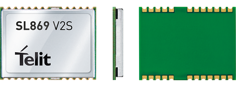
The Jupiter SL869-V2S GPS module. Photo: Telit Wireless Solutions
Telit Wireless Solutions, a global provider of high-quality machine-to-machine (M2M) modules and services, today debuted the Jupiter SL869-V2S GPS module, designed for easy migration between a full-GNSS solution for top-ranked applications and a simple GPS-only solution for less demanding applications.
The Jupiter SL869 V2S supports GPS as well as QZSS constellations and is ROM based. Geo-location data is delivered using NMEA protocol through a standard UART port. It supports ephemeris file injection (A-GPS) as well as Satellite Based Augmentation System (SBAS) for increased position accuracy. Its onboard software engine is able to locally predict ephemeris three days in advance starting from ephemeris data broadcast by GNSS satellites, received by the module and stored in the host flash memory.
Key benefits include:
Pin-to-pin compatibility with JN3/xL869 family
Same protocol used in SL869 V2
Straightforward migration between full-GNSS solutions and GPS-only solutions
SBAS support, for increased position accuracy
Assisted GPS
The SL869 V2S can replace the JN3, SL869 or SL869 V2 — allowing customers to design once and interchangeably mount the appropriate solution depending on the required features. The xL869 is Telit’s GNSS unified form-factor family, which allows customers to select among different GNSS technologies and feature sets. Modules in this family are offered in a 16 x 12.2 mm, 24-pad, LCC package.
“The new SL869 V2S module is designed to be easily swapped with other xL869 modules for enhanced simplicity and scalability,” said Taneli Tuurnala, CEO of Telit GNSS Solutions. “It is an ideal example of how buying a module from Telit enables our customers to avert the need to keep track of the latest chipset technology on their own. We keep them on top of the best available technology, pre-packaged in a module that is easy to replace as needed, without having to redesign their entire application to stay up to date.”
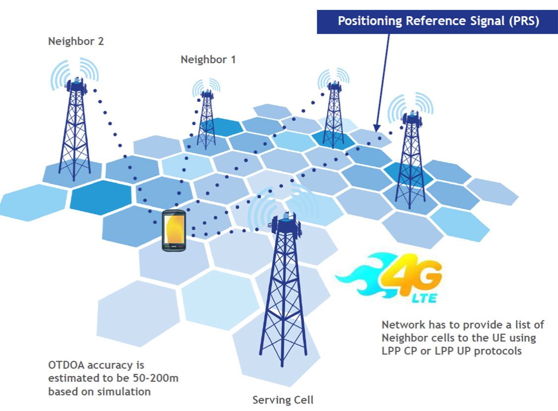
LTE brings a promise of improved location accuracy with new positioning technologies and their integration using hybrid techniques. Although established technologies such as A-GNSS (A-GPS and A-GLONASS) provides excellent performance in environments with a clear view of the sky, performance is often poor indoors, where detection of satellite signals is limited. In LTE, current standards support Observed Time Difference of Arrival (OTDOA), an advanced cellular positioning technology that can augment A-GNSS and provide a more accurate location fix for indoor scenarios.
With large-scale VoLTE rollouts imminent, leading operators are confronted with the need for extensive and complex testing of LTE positioning technologies to ensure VoLTE E911 works well from day one. Additionally, the FCC, whose current E911 regulations apply only to outdoor environments, has proposed stringent indoor requirements as a response to increased mobile usage for emergency calls and lack of accurate positioning information on calls that originate indoors.
“Roughly 70 percent of 911 calls are placed from wireless phones and a majority of these calls originate indoors, so there is a real urgency in providing better location accuracy for mobile users, wherever they are calling from,” said Nigel Wright, vice president at Spirent Communications. “Spirent is currently working with all the key industry players to evaluate OTDOA and its integration with other positioning technologies, and to enable operators to meet the location requirements for VoLTE E911 and the evolving FCC requirements.”
Spirent 8100 LTS has won widespread acceptance as the leading platform for location testing in the wireless industry, and with this latest capability is now able to support OTDOA Position Calculation Function (PCF). Minimum performance testing for OTDOA looks only at the raw measurements from the device, whereas use of OTDOA PCF enables full verification of a device’s position accuracy performance. Recognizing its importance, leading carriers have established their own OTDOA positioning performance requirements beyond bare minimum standards. Ensuring that devices fully meet these requirements as well as the evolving FCC regulations for E911 requires comprehensive testing.
An independent study of indoor tests of a hybrid wireless location technology was submitted today to the Federal Communications Commission (FCC) by wireless location engineering firm TechnoCom. The study demonstrates that existing technologies can satisfy location requirements within the timeframe proposed by the FCC in its draft rule on indoor 911 accuracy for wireless calls, according to True Position, which commissioned TechnoCom to perform the testing.
Multiple wireless carriers have challenged the technical feasibility of the proposed rule, claiming that existing technologies cannot satisfy the proposed accuracy requirements, with a spokesperson for the industry trade association claiming the rule represented “aspirational target setting.”
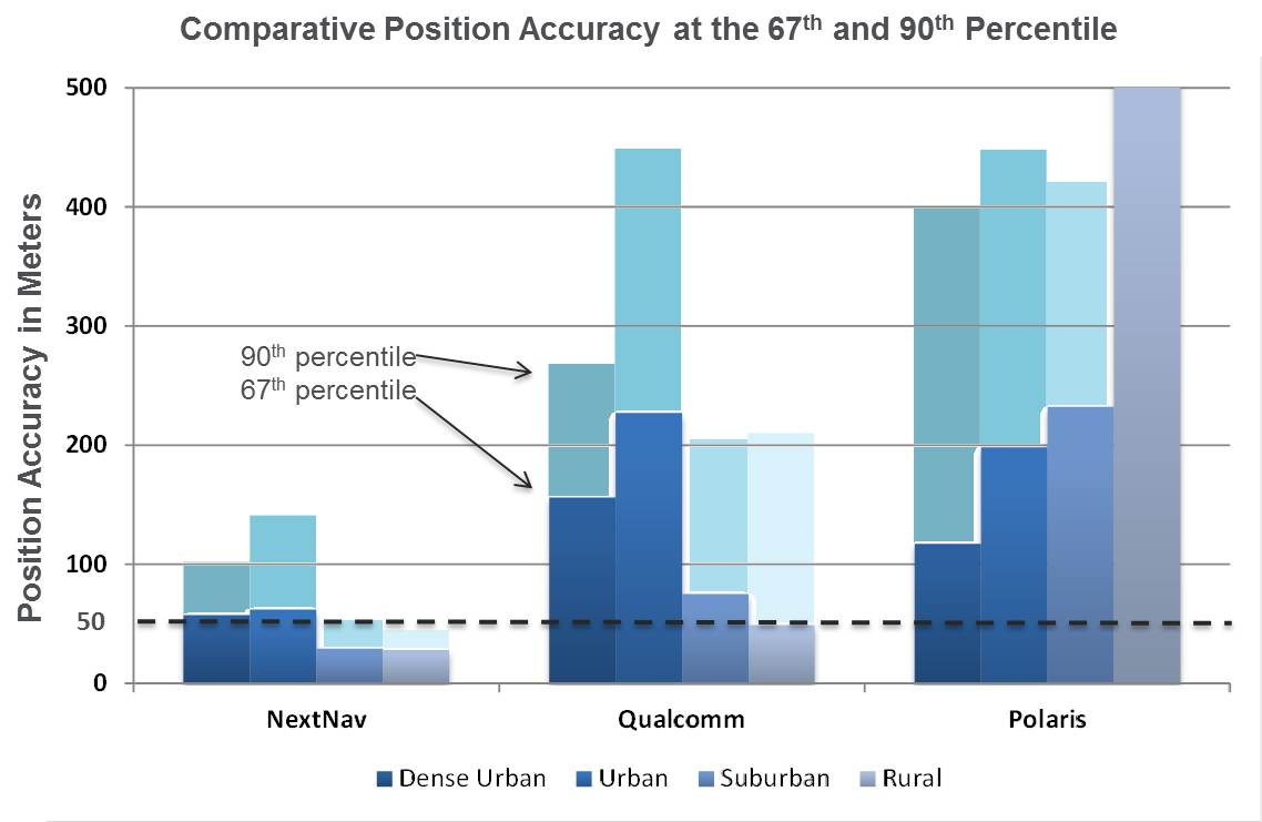
The results filed today by TechnoCom disprove those assertions, showing that viable technology exists in the market today, True Position said. According to TechnoCom’s findings, “The outcome is a current overall performance that readily meets the FCC’s proposed location performance threshold for indoor wireless E911 at the 67th percentile. The demonstrated performance even comes very close to meeting the 50 meter threshold at 80%, which is intended for 5 years from adoption of the proposed rules.”
Multiple other vendors have submitted filings to the FCC claiming that their technologies would also satisfy the requirements of the rule on the timeline proposed by the FCC.
“These results should prove helpful to the FCC as it moves toward reaching a resolution on its proposed rule on indoor location requirements,” said Craig Waggy, CEO of True Position. “We know that accurate location information is vitally important to American consumers, and that the FCC is intent on remedying the lack of wireless indoor location requirements for calls placed to 911 from wireless devices.”
The tests were conducted using True Position’s commercially available Uplink Time Difference of Arrival (UTDOA) technology standalone, and a hybrid solution consisting of Assisted GPS (A-GPS) and UTDOA technologies, and included indoor testing in both urban and suburban environments in Wilmington, Delaware, and surrounding areas.
For the testing, buildings of varying sizes, construction materials and use were selected by the independent firm, and a total of 62 test points were selected among 16 buildings. In all cases, the test buildings and test points remained anonymous to True Position until the conclusion of the testing and delivery of all results to the independent firm.
In early 2013, TechnoCom conducted the indoor accuracy testing for the FCC’s Communications, Security, Reliability and Interoperability Council (CSRIC). The same location and measurement methodologies were used in these tests.
The FCC has estimated that 10,000 lives could be saved each year if calls made to 911 from wireless phones had accurate location information.
Tri-Band Multi-Constellation GNSS in Smartphones and Tablets
This article presents a single-chip BeiDou/Galileo/GLONASS/
GPS/QZSS/SBAS architecture for use in cell phones and tablets. The authors explain the advantages to end users of multiple constellations. They also examine the details of system interchangeability, multi-system issues, and how assisted-GNSS data operates with all constellations, including BeiDou.
By Frank van Diggelen and Kathy Tan
With GPS, GLONASS, SBAS, BeiDou, QZSS, and Galileo there are over eighty operational satellites. Why do we need all these satellites in the first place? The answer is simple: in urban environments we want a few (six to eight) good satellites with an unobstructed line-of-sight (LoS) to the receiver and good horizontal dilution of precision (HDOP). In order to achieve this, we need many more satellites in space than any single constellation. In this article, we address the following issues.
Receiver intersystem RF bias with a tri-band front-end. BeiDou uses a different RF section than GPS/Galileo/QZSS/SBAS and GLONASS. As a result, there is a receiver intersystem bias between BeiDou and each of these other systems—not just because BeiDou is on a different frequency, but because of the different RF path through the receiver. We explain how this bias is calibrated and removed.
In the space segment there are intersystem biases primarily caused by differences in time standards. We discuss time management and show how the different systems can be made interoperable.
BeiDou Assistance. In order to realize the benefits mentioned, we need infrastructure deployment for BeiDou assistance in accordance with 3GPP standards. We will discuss what is available, and what is left to do.
Coverage outside of China. Europeans can see more BeiDou satellites than Galileos. At the time of writing (March 2014) they could see approximately twice as many. Thus, when used in a multi-GNSS receiver, BeiDou is far from being just a regional system. We will provide coverage analysis, and live-test data, including a focus on Europe.
Finally, we will demonstrate all of the above in practice, explaining and showing how interchangeability is achieved, and where first fixes can be computed with no more than one of each satellite type.
Figure 1 illustrates the point referenced at the beginning, that we need many more satellites in space than any single constellation.
All of the lines in Figure 1 show signals that were actively tracked by the receiver at the position shown on the right. The orange lines are to satellites that are blocked, but the reflected signal is tracked. We do not want to use these measurements if we can help it, so we need many satellites to provide enough LoS signals.
Let’s look at the HDOP of the LoS signals. In this example, the HDOP for the three LoS GPS satellites was 50. For the three LoS GLONASS satellites, the HDOP was 45. However, with the combined GNSS constellation, the HDOP for the six LoS satellites was 2.2. In other words, we expect about a 20x accuracy improvement by using the combined constellation.
There are many places and times in cities where we see just one or two direct LoS signals from a particular constellation, and we need more than just GPS and GLONASS to get the desired number of good signals, thus explaining the desire and need for all available constellations.
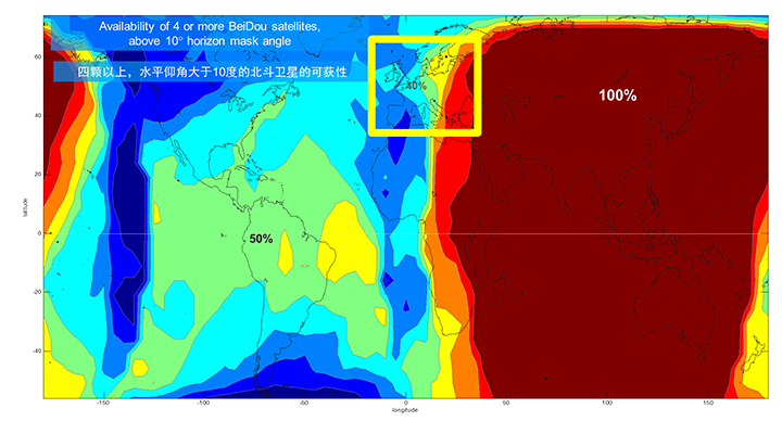
We’ll now look at the coverage provided by BeiDou2, which has five Geostationary satellites (GEOs), five inclined Geosynchronous satellites (GSOs), and four Medium Earth Orbit satellites (MEOs). With this 14-satellite constellation, the global coverage is as shown in Figure 2. This figure shows the percentage of time in a day that four or more BeiDou satellites are visible above a 10-degree mask angle. In the Asia-Pacific region, where the GEOs and GSOs are positioned, the coverage is predictably 100 percent. In fact, there are seven or eight BeiDou satellites visible in much of this region most of the time.
Figure 2. BeiDou2 global coverage.
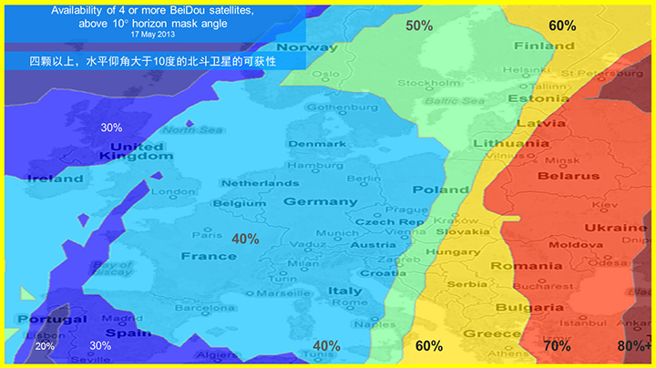
As shown in Figure 3, outside the Asia-Pacific region the coverage is also interesting. We see that at least four BeiDou satellites are available over Europe about half of the time. This is quite significant given the previous discussion; even one or two extra satellites can make all the difference in an urban environment. Another notable fact is that, for now at least, Europe can see more BeiDou than Galileo satellites.
Figure 3. BeiDou coverage over Europe. The different colors show the percent of time that four or more BeiDou satellites are visible above a 10° mask angle.
Technical Requirements
There are five significant technical requirements that we want to satisfy when creating a multi-GNSS receiver for consumer applications:
Three Separate RF Paths. To acquire and track all of the satellites already mentioned, we need three separate RF paths. Details follow in Section 3 (Front-End Architecture).
Search and Track capability for all visible GNSS satellites. The receiver must have the ability to search a very large number of code-frequency bins at once.
Host-Based. As much as possible, we want to make use of the host application processor (AP) and memory. This allows for tight integration with assistance data (which is coming from the host), other sensors, and other wireless data (such as Wi-Fi and Bluetooth for indoor locations). A host-based architecture also keeps size and cost as low as possible.
With Host-Offload. A significant trend in location applications is the need for “always-on low power” location. The host AP cannot be used for continuous position updates, since it draws too much power. So, while we want host-based location when the host AP is active (such as when navigating with turn-by-turn directions and a map), we also want a host-offload capability so that the GNSS chip can compute positions internally while the host is asleep.
Interchangeability. The ultimate requirement for multi-system GNSS is the ability to use any combinations of satellites as if they were all in the same constellation. This is summarized as “any four satellites will do.”
Front-End Architecture
From a cell phone/tablet perspective, the signals in space are all in the L1 band, with frequencies as shown in Figure 4. The key architecture feature of the GNSS front-end is that it should have three separate RF chains for the three separate frequencies-of-interest; see Figure 5.
Figure 4. Frequencies-of-interest for GNSS in cell phones.Figure 5. Front-end architecture showing three RF chains.
Baseband Architecture
The preferred architecture of a chip, as shown in Figure 6, is host-based to take advantage of the large host CPU when it is active. When the host CPU is asleep, a small, low-power, on-chip CPU is leveraged for background “always on” location. This enables applications such as geofencing to run without significantly reducing battery life.
Figure 6. Block diagram of the preferred architecture, showing a host-based configuration that includes a host-offload capability for geofencing and position caching on-chip when the host is asleep.
When the host is active, such as when you are actively using the phone for turn-by-turn navigation, the host AP is on and we want to make as much use as possible of the host AP and memory. This allows for tight integration with assistance data coming from the host, other sensors, and other wireless data (such as Wi-Fi and Bluetooth for indoor locations). A host-based architecture also keeps size and cost as low as possible, even with host-offload capability, which adds very little to the size of the chip.
Receiver Intersystem RF Biases
With the three different bands of frequencies, we will get RF group delays in the receiver front-end. These must be calibrated out by the receiver’s designer as part of the chip’s system design. If the group delay between BeiDou and GPS is not calibrated, it will lead to approximately three meters of bias between the two systems (Figure 7). Once it is calibrated, there is essentially no bias.
Figure 7. L1 frequency spectrum for BeiDou2, GPS, Galileo, QZSS, SBAS, and GLONASS.
Satellite Intersystem Biases
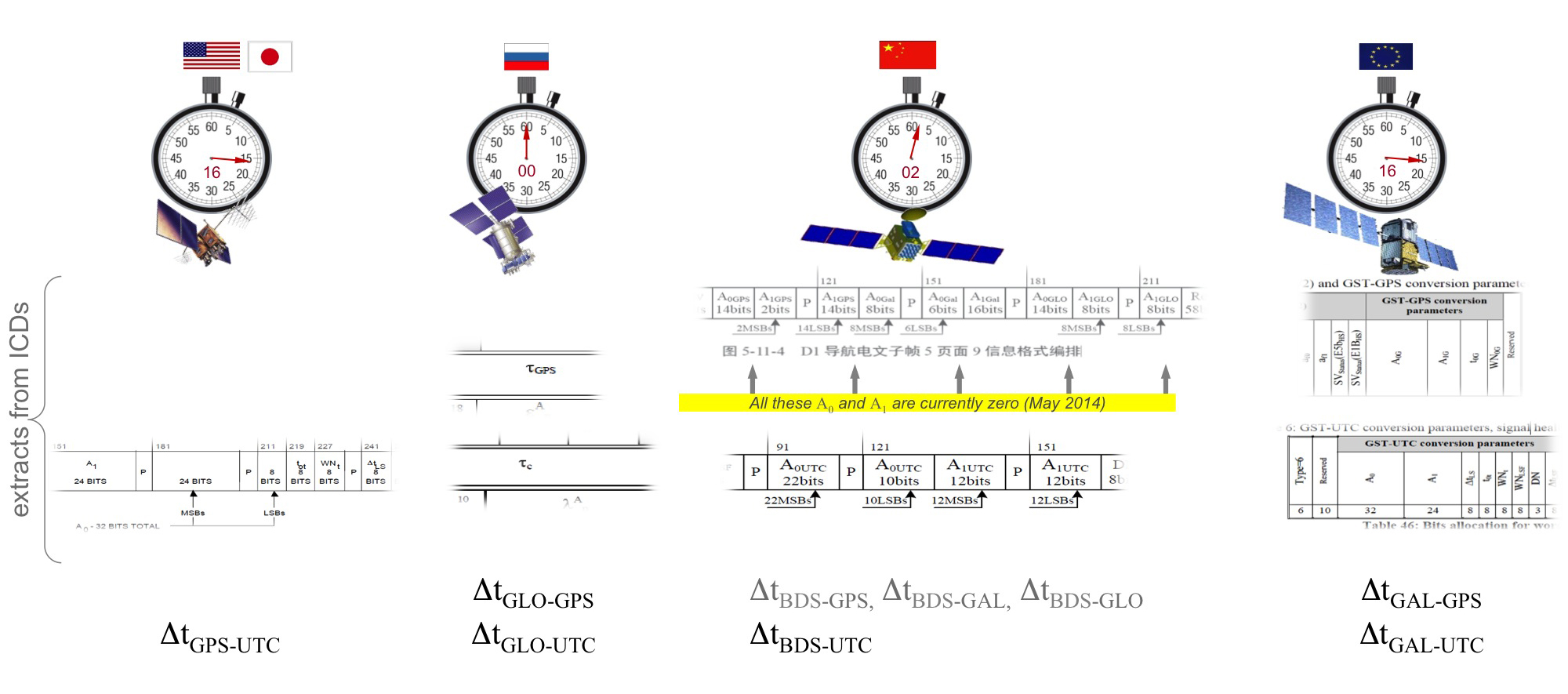
Different GNSS constellations run off their own master clocks; referenced to different realizations of UTC. GPS is referenced to UTC (USNO), QZSS is referenced to UTC (NICT), GLONASS to UTC (SU), BeiDou to UTC (NTSC), and Galileo to UTC (INRIM). GLONASS UTC (SU) differs from the others by 3 hours.
Furthermore, different systems treat leap seconds differently. This is indicated by the red arrows in the clocks in FIGURE 8. GPS, QZSS, BeiDou and Galileo system times are continuous and ignore leap seconds. Thus, each system time is ahead of UTC by a number of leap seconds. GPS time started in 1980 in synch with UTC; there have been 16 leap seconds since, so now GPS is 16 seconds ahead of UTC. QZSS and Galileo system times were started in synch with GPS. BeiDou system time was started in 2006 in synch with UTC; there have been 2 leap seconds since, so now BeiDou is 2 seconds ahead of UTC. GLONASS system time, on the other hand, includes leap seconds.
Apart from this, each of the different realizations of UTC is within several nanoseconds of the others.
To combine measurements from these different systems and avoid any time-induced intersystem biases, we need to resolve the time offsets. Each system transmits the delta-time between its system time and the systems that preceded it, as listed in Figure 8. To combine the systems, we either need to decode these data messages or obtain the delta-time values from Assisted GNSS.
Figure 8. Intersystem time differences and broadcast delta-time values from each system.
Note, however, that in the BeiDou broadcast Nav message the intersystem time-offset data values are all set to zero (even though the true offsets are not zero).
Assisted-GNSS Including BeiDou
Assisted GNSS, or A-GNSS, increases sensitivity and decreases the time-to-first-fix of a receiver by providing assistance data in the form of the receiver’s approximate position, time and frequency, as well as all data that the receiver might decode from the broadcast signals. The assistance data may also include data beyond what is broadcast, in particular, let’s focus on BeiDou time offsets. The BeiDou time offset to the other systems is included in the BeiDou broadcast Nav message as shown in Figure 8; however, at present these data values are all set to zero (even though the true offsets are not zero). Thus, in order to get these offsets and integrate BeiDou properly into a combined GNSS system, one must compute the offsets at a reference station and provide them as part of the assistance data, as shown in Figure 9.
Figure 9. A-GNSS provides broadcast satellite data over some other wireless network, as well as time-offsets between the different pairs of systems.
Commercial Implementation
The preferred architecture described in this article has been implemented in a commercial GNSS receiver that is now available for commercial host-based products, such as cell phones and tablets. The chip, Broadcom’s BCM47531, is the first consumer GNSS chip with a tri-band front-end capable of acquiring and tracking satellites from GPS, SBAS, QZSS, GLONASS, and BeiDou constellations, simultaneously; and operating in host-based mode for navigation and in host-offload mode for Always-On location.
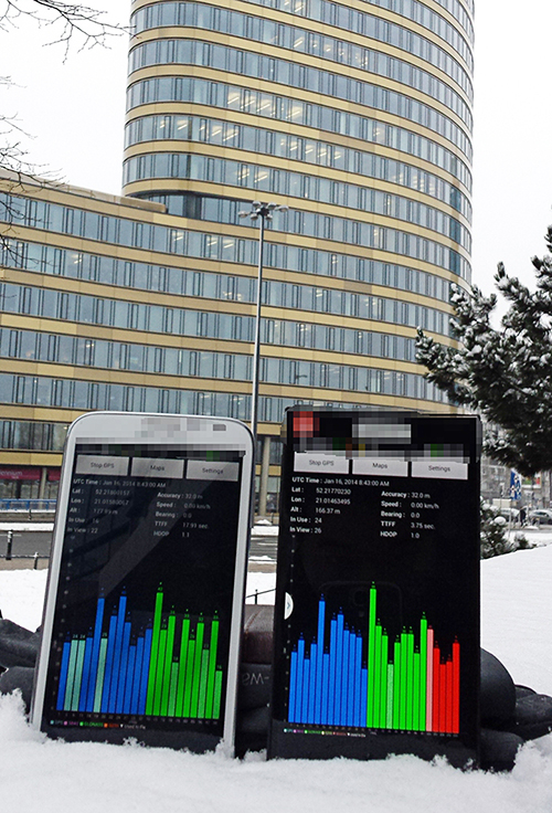
Broadcom has collaborated with leading smartphone manufacturers to launch the first wave of BeiDou enhanced consumer smartphones. Figure 10 shows one of these smartphones being tested in Europe. Note the number of BeiDou satellites in view. As predicted by the availability plots shown earlier, there are many BeiDou satellites in view (in this case, six).
Figure 10. GPS/GLONASS phone and GPS/GLONASS/BeiDou phone being tested in Warsaw, Poland. Note the six BeiDou satellites (red) that are seen and tracked by the BeiDou phone.
Interchangeability: Any Four
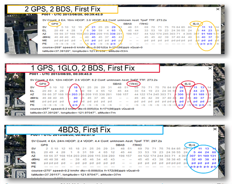
Now that we have addressed all of the major issues related to integrating different GNSS systems (in particular BeiDou), we can demonstrate the payoff.This is the achievement of interchangeability, where any GNSS satellites can be used together, as if they all belong to a single constellation. Figures 11 and 12 show assisted cold starts, where first fixes are obtained with no prior knowledge other than that provided by A-GNSS data. In each case, we show a different combination of satellites; including one satellite from each of four different constellations, and all four from BeiDou.
Figure 11. Interchangeability: Position fix with 1 GPS satellite, 1 GLONASS, 1 QZSS, and 1 BeiDou. The receiver is in Perth, Australia, where all of these constellations can be seen.Figure 12. Interchangeability: Assisted cold start, first fixes. Blue numbers show the satellites used in the position fix (top: two GPS and two BeiDou; middle: one GPS, one GLONASS, and two BeiDou; and bottom: four BeiDou only). The receiver is in San Jose, California, where four BeiDou satellites can be seen some of the time (some of the BeiDou GSOs can be seen and all the BeiDou MEOs can be seen for a few hours each day).
Multi-Constellation Robustness
While this article was being edited, the GLONASS system provided us with the most dramatic demonstration yet of the need for, and benefits of, multi-constellation receivers. On April 2, 2014, the GLONASS system failed spectacularly for a period of 11 hours. Receivers that used GPS and GLONASS had very large position errors, or no positions at all. While the receiver discussed in this article, the BCM47531, operated seamlessly. This receiver tracked GPS, GLONASS, QZSS and BeiDou satellites, correctly identified the faulty GLONASS satellites, and automatically stopped using them.
The details of the incident are as follows: The GLONASS control system uploaded incorrect orbit data to several satellites. When receivers used these satellites they had position errors of hundreds of meters, or no positions at all. At that time, the BCM47531 was being tested alongside a GPS/GLONASS receiver, and we have the data to show what happened. The receiver using only GPS/GLONASS suffered position errors of ten thousand meters, and long periods with no position at all; at the same time the multi-constellation receiver produced continual positions with normal accuracy. Figure 13 shows the test data — the left most image shows the route being driven, the middle image shows the data from the GPS/GLONASS receiver, and the right image shows the data from the BCM47531 multi-GNSS receiver. Figure 14 shows the details of the multi-GNSS receiver, you can see that no GLONASS satellites are being used.
FIGURE 13. Side-by-side tests of GPS/GLONASS receiver and multi-constellation receiver during the GLONASS incident of April 2, 2014. The GPS/GLONASS receiver produced errors of ten thousand meters and long periods with no position at all, while the multi-constellation BCM47531 operated seamlessly.FIGURE 14. Detail from the multi-constellation receiver when there is a problem with some satellites. The errors are recognized automatically by algorithms comparing the measurements to redundant measurements from the extra constellations, and the erroneous signals are not used.
This incident may raise the question: Why use GLONASS at all, why not just GPS? The answer is that in urban canyons, such as where this test was done, GPS alone does not have enough satellites to give the performance now expected in consumer products — for the reasons explained in the beginning of this article. Also, GPS, although it has been more reliable than GLONASS, is not immune to failures or jamming itself. The lesson of this incident is that reliability and accuracy comes from the combination of all the available constellations, with a receiver that can use the signals interchangeably.
Conclusion
We have shown the preferred architecture for a consumer GNSS receiver that includes all of the available constellations. We have addressed the major requirements of such a receiver for the consumer market, in particular, for cell phones and tablets. A receiver that meets these requirements is now available, the Broadcom BCM47531, has been designed into a new generation cell phones and tablets for 2014. Finally, we have shown how, with this receiver, the ultimate GNSS goal of interchangeability can be achieved.
Frank van Diggelen is vice president of technology at Broadcom Corporation, a consulting professor at Stanford University, and inventor of coarse-time GNSS navigation, co-inventor of Long Term Orbits for A-GNSS, and author of A-GPS: Assisted GPS, GNSS, and SBAS.
Kathy Tan is a senior principal engineer at Broadcom Corporation. She has worked on GNSS development and Assisted GNSS for Ashtech, Magellan, Global Locate and Broadcom. She received her MS and BS in electrical engineering from Fudan University, China.
Swiss u-blox introduces the surface-mount MAX-M5Q, a compact satellite positioning module that supports GPS and GLONASS, as well as Japanese QZSS satellite GNSS systems. High-performance GPS/GLONASS parallel operation is also supported to enhance positioning speed and accuracy.
Designed for use in rugged environments and wide temperature range, MAX-M5Q is intended for industrial machine-to-machine (M2M) applications as well as Russia’s ERA-GLONASS emergency call system. MAX-M5Q enhances positioning in poor GNSS satellite visibility conditions as well as in high latitude and polar regions, u-blox said.
“With parallel GPS/GLONASS operation, MAX-M5Q is able to track all 50 and more U.S. and Russian satellites to deliver incomparable speed, accuracy, and positional availability,” said Thomas Nigg, vice president of Product Marketing at u-blox, “Its compact size and high-reliability makes it an ideal positioning solution for mobile resource management and ERA-GLONASS emergency call applications.”
With dimensions of 9.7 x 10.1 x 2.5 mm, MAX-M5Q is the newest member of u-blox’ MAX GNSS LCC module series. Additional features include autonomous A-GPS that reduces warm start TTFF by as much as 90%, and an embedded data logger which can store location information to internal Flash memory for up to 16 hours at 15 second intervals.
Indoor location research and fielded developments currently focus on consumer-level applications, mostly using mobile phone handsets, but this work will hopefully also benefit professional and high-precision uses of GNSS. Indoor location technologies could be of particular interest in machine control for warehousing, industrial assembly, indoor and even underground mapping, underground mining, in forestry where dense canopy virtually cuts out GNSS, construction, and other areas where sky-view is limited or negligible.
Tune in to Indoor Nav Webinar Thursday
Tune in to GPS World’s webinar, “Indoor Positioning and Navigation: Results of the FCC’s CSRIC Bay Area Trials,” on Thursday, April 18. Speakers include Khaled Dessouky (Technocom); Ganesh Pattabiraman (NextNav); Norm Shaw (Polaris Wireless); and Greg Turetzky (CSR). Registration is free.
Professional users will want to keep abreast of developments in the E-911 area, and be aware as achievable accuracies begin to approach what could be possible for precision applications. Right now, that’s maybe a pretty big stretch, but taking a look periodically is a good idea. A recent round of landmark tests by the Federal Communications Commission (FCC) provides just such an occasion for a look-in.
The U.S., E-911 legislation put in place back in 2001 required that both landlines and cellphones should provide the location of callers to within specific accuracy levels. Location information was to be sent transparently to Public Safety Answering Points (PSAPs) which would allow fire/rescue/police personnel to be dispatched to the location of the 911 call. For mobile phones, cellphone manufacturers and network providers forged ahead and implemented a number of location strategies using differing technologies — all require being outdoors where a clear sky-view is available.
GPS and augmented GPS technologies were only part of the cellphone solution. Other implementations included use of the cell-signal itself, along with an extensive database that can contain, amongst other things, signal attributes and network asset locations. Turns out that, today, around 60 percent of mobile phone calls are made within buildings, so the FCC started to investigate how to bring E-911 capability to indoor calls.
In 2011, the FCC commissioned a group called the Communications Security, Reliability and Interoperability Council (CSRIC), and Working Group 3 (WG-3) is the one currently investigating what can be done for indoor E-911 location. Drawn from interested industry participants, the WG-3 Location-Based Services (LBS) sub-group set about finding what technologies exist, how well they work, and how they could be applied to E-911. Now, there are a lot of people trying to crack this problem and many, many ways that it’s been tackled — all of which are at different stages of development and with differing levels of capability. In order to make definitive progress, WG-3 LBS decided that a test-bed was the best way to evaluate and compare what’s currently available.
Seven vendors signed up initially, but only three — NextNav, Polaris Wireless, and Qualcomm — completed the rigorous testing, which set out to basically establish horizontal and vertical accuracy, speed of location, and reliability and consistency of results for each system. The trial tested the performance of location systems across urban, suburban and rural areas in the San Francisco Bay Area. More than 13,000 test calls were placed from various tested technologies in 75 different indoor locations selected by participating public safety organizations from around the U.S. Click here for the full report.
In the tests, Polaris Wireless used an RF pattern matching/fingerprinting technique, Qualcomm used a hybrid Assisted-GPS (A-GPS)/Advanced Forward Link Trilateration (AFLT) system, and NextNav used wireless beacon technology. NextNav came out on top, and largely within the magical 50-meter “search ring” requirement, and was the only vendor to provide vertical location capability.
NextNav uses pressure transducers in its beacons and in the handheld units to accurately measure calibrated altitude — within about 2 meters — so it can actually report the floor where the handheld is located; it’s the only system tested that was able to do so. Apparently the use of MEMS pressure sensors in cellphones is forecast to increase to 681 million units in 2016, so this could be the right approach.
NextNav is focusing on the San Francisco market, where the company has fielded a significant number of beacons, but it has also placed beacons in another 40 metropolitan locations across the U.S. NextNav has acquired appropriate spectrum rights to transmit a 900-MHz “GPS-like” signal that’s synchronized to GPS. This enables good penetration into most urban buildings — both high-rise and those with fewer floors.
To support adoption of its solution, NextNav is working with a chipset manufacturer to incorporate processing of its location signal within an upcoming spin of an embedded cellphone chipset. While other solutions have adopted Wi-Fi and cell-signal solutions, NextNav contends that its approach is the most cost effective, as beacon deployment is geographically less dense and can be amortized over so many users.
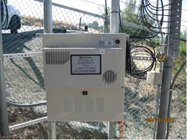
NextNav Beacon.
Other solutions also apparently rely on the use of databases that store signal characteristics and a number of other parameters – the CSRIC report highlights the complexity this brings to database management and maintenance. NextNav also has a database, but this is basically to store records of location, cable configurations and calibration data. This is only used to ensure consistent performance of their system; it’s not required for network operation or location.
Higher precision applications would also benefit from this type of augmentation in the same way that WAAS users achieve higher accuracies, except this system uses local beacons, and there could be the potential for even higher precision with known fixed beacon locations within urban environments. As commercial UAV applications grow, it’s not impossible that there will be higher precision flight applications within cities, for geo-location surveying, building and outside appliance inspections, signal mapping, traffic mapping, road-work repair monitoring — in fact, many of the monitoring activities we see daily in towns and cities where a view of the sky can be particularly restricted.
The CSRIC participants are not the only ones pursuing the holy grail of indoor location. As mentioned, seven different location vendors/technologies began the process to demonstrate their performance indoors through the common test bed, but only three completed the process. The others remain highly motivated and involved, however, and at work tuning their varied solutions. The WG3 report states, “The following location vendors showed initial interest in having their technologies tested and highlighted through the test bed process, but ended up not participating in the Stage 1 test bed, for a variety of reasons.
LEO Iridium Satellite-based Positioning (BoeingBTL).”
Meanwhile, promising indoor location research goes on at a number of commercial and academic institutions, such as the University of Calgary PLAN group, which has focused on integration of Wi-Fi and GPS. An upcoming paper reports that Wi-Fi, using the 802.11 standards, can be employed in several different ways as a complementary positioning technology for GPS/GNSS navigation, and the two can be used in an integrated framework to provide a continuous and robust positioning service.
Another promising component for indoor location could be the recent release of a software application by Baseband Technologies, which can provide rapid ephemeris for up to 28 days, between ephemeris downloads from GPS directly or over cellphones from the Internet. But indoor location warrants much more extensive treatment than these few random comments — what’s summarized here are only some recent developments in E-911.
There will likely be another round of E-911 test-bed activities if funding and management issues are resolved. See CSRIC WG-3 LBS Subgroup member Greg Turetzky’s “Expert Advice” column from GPS World for perspective and a forward look. We can anticipate even wider participation by differing technologies and even greater levels of performance in future. Longer term progression towards higher precision professional applications seems to be inevitable.
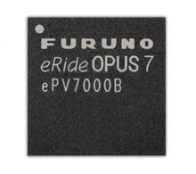
Furuno Electric Co., Ltd., has announced that new multi-GNSS receiver chips eRideOPUS 6 and eRideOPUS 7 will be available in August. The new receiver chips are multi-GNSS compliant single-chip LSIs, capable of concurrently receiving signals from multiple satellites in GNSS systems and satellite-based augmentation systems, as well as Japan’s Quasi-Zenith Satellite System. Both chips receive signals from GPS and Galileo; the eRideOPUS 7 also receives GLONASS signals.
The ability of concurrently receiving GNSS/GNSS augmentation signals from multiple satellites from different satellite services means that the receivers have more probability of acquiring a greater number of satellites at any single time. Subsequently, position stability as well as accuracy will be greatly improved, minimizing the chance of a position lost. Also, the receiver chips incorporate an enhanced level of noise rejection capability, implementing the anti-jamming function as well as the improvement of multipath mitigation.
Time-to-first-fix capability of the existing eRideOPUS 5 (no more than 1 second when hot started) is retained in these new receiver chips with a combination of A-GPS compatibility and self-ephemeris extraction. Moreover, the position update rate of the new receiver chips is greatly improved, achieving a 10-Hz update (every 0.1 second), which is twice as fast as the capability achieved by eRideOPUS 5.
The new receiver chips are capable of dead-reckoning navigation, using a gyro sensor and vehicle speed pulse signals, a gyro sensor and an acceleration sensor, and wheel tick data taken from a CAN-Bus network, achieving high positioning accuracy even in locations where satellite signal reception is not available, such as inside tunnels.
In May 2013, Furuno is planning to start the delivery of evaluation kits for the receiver chips so that third-party manufacturers can evaluate the feasibility of incorporating the receiver chips into their products, and in August 2013, the new compact GNSS receiver module GN-86/GN-87 as well as
dead-reckoning-capable GV-86/GV-87, using these new receiver chips, will be made available for automotive navigation systems as well as eCall systems.
u-blox, the Swiss positioning and wireless chip and module company, has received approval for its LISA-U110 UMTS/HSPA wireless module from SK Telecom, Korea’s largest mobile telecom operator with more than 50 percent market share. SK Telecom provides multimedia services and connectivity to 24 million customers throughout South Korea.
The certification allows the LISA modem to be used in a wide range of consumer and M2M applications operating over SK Telecom’s nation-wide 3G network including vehicle infotainment, supply chain management, industrial automation, metering, security, and location-based services.
“We are very pleased that SK Telecom has chosen to work with us on this 3G approval. Our compact and high-speed LISA 3G module is a perfect fit with their strategy to provide converged wireless services supporting entertainment, business and financial applications. Our local support in Korea was a key factor in obtaining this certification” said Samuel Ji, u-blox Country Manager, Korea.
The LISA-U110 is an embedded wireless UMTS/HSPA module delivering high data rates in 3G networks intended for consumer, automotive and industrial applications. For telematics applications, the series provides easy integration with u-blox GPS, GLONASS and QZSS receivers.
LISA modules come in SMT form factor and have a very small footprint, allowing easy mounting on any application board. The LISA form factor enables easy manufacturing, u-blox said, as well as simple migration from u‑blox’ GSM/GPRS modules. Support for A-GPS and u-blox’ CellLocate positioning technology is embedded to facilitate advanced telematics applications including indoor positioning.
Features include compatibility with quad-band GPRS/EDGE, low power (idle mode less than 2 mA) and operating temperature -40 to +85 deg. Celsius. RIL software for Android and Embedded Windows is available free of charge.
LISA modules are manufactured in ISO/TS 16949 certified sites and are fully qualified according to ISO 16750 — Environmental conditions and electrical testing for electrical and electronic equipment for road vehicles to provide high durability and reliability.