The approval paves the way for Orolia’s ELT-DT to play essential roles in meeting the aviation industry’s advanced safety mandates worldwide
The Ultima-DT emergency locator. (Photo: Orolia)
Orolia is the first company to receive certification from Cospas-Sarsat and the European Union Safety Agency for its new-generation distress tracking emergency locator transmitter, the Ultima-DT.
The approval verifies Orolia’s continuous advancements in global beacon technology, including securing a single source, multi-year program contract to supply ELT-DTs for all Airbus aircraft programs.
Cospas-Sarsat is an international, humanitarian search-and-rescue system that uses space-based technology to detect and locate model 406 emergency beacons carried by ships, aircraft or individuals venturing into remote areas, often inaccessible by GNSS signals. The system consists of a network of satellites, ground stations, mission control centers (MCCs), and rescue coordination centers (RCCs) that work together when a 406 beacon is activated.
“Being the first company to certify a distress tracking ELT shows again Orolia’s unique ability to provide the industry with the most innovative safety solutions,” said Jérôme Ramé, Orolia’s aviation and military product line director. “With Ultima-DT, we address the EASA-mandated requirement for the location of aircraft in distress, but also the market need for an ELT meeting the most recent safety standards.”
Orolia developed the Ultima-DT in response to aviation safety mandates to improve global aircraft tracking. As per the ICAO Global Aeronautical Distress and Safety Systems (GADSS) recommendation and European Union mandate, all new aircraft delivered from January 2024 shall be able to autonomously report their location anywhere in the world and determine the end-of-flight location to help rescue teams rapidly locate the aircraft and recover flight recorders.
Unlike traditional automatic fixed ELTs and stand-alone units, the Ultima-DT is tightly connected to the avionics system. It activates upon detecting a potential distress condition and starts transmitting automatically while the aircraft is still in flight. This next-generation ELT autonomously acquires the aircraft’s location and sends a 406-MHz message in real-time, including the accurate location, to the Cospas-Sarsat distress alert organization.
The Ultima-DT is also the first ELT to fully comply with the latest EASA/FAA safety requirements for non-rechargeable lithium battery-powered equipment through (E)TSO-C142b. As part of its efforts to support airlines in their regulatory compliance projects, Orolia is also offering its portable Ultima-S ELT, which aims to meet these special conditions.
Global corporation VIAVI Solutions Inc. has completed the acquisition of Jackson Labs Technologies, a leader in positioning, navigation and timing (PNT) solutions for critical infrastructure serving both military and civilian applications.
Jackson Labs develops and supplies modules, subsystems and box-level solutions that include front-end receivers, transcoders, rack-mounted equipment, and patented retrofit technology. Their broad customer base includes armed forces, defense contractors, energy distribution infrastructure, low-Earth-orbit (LEO) operators and 5G service providers.
Jackson Labs’ next-generation M-code solutions complement and advance VIAVI’s timing and synchronization portfolio at a time when PNT requirements for defense, space, commercial aviation, transportation and telecommunication networks are expanding and becoming increasingly critical.
“As telecommunications, avionics and mission-critical infrastructure adopt next-generation technology, legacy timing and synchronization protocols are no longer sufficient. Jackson Labs is a trusted provider of PNT solutions in these markets, and we look forward to addressing these opportunities together,” said Oleg Khaykin, president and CEO of VIAVI. “With this acquisition, we are continuing to drive operational scale via the addition of advanced technology and high-performance products that address market segments with strong growth and profitability.”
“Being a part of VIAVI will significantly expand Jackson Labs Technologies’ market reach worldwide, and allow us to further deliver world-class solutions for the rapidly developing PNT landscape as it enters a new era,” said Said Jackson, CEO of Jackson Labs Technologies.
DelMorgan & Co. acted as the exclusive financial advisor to Jackson Labs in connection with the transaction. Terms of the transaction are not being disclosed.
About VIAVI
VIAVI s a global provider of network test, monitoring and assurance solutions for communications service providers, enterprises, network equipment manufacturers, original equipment manufacturers, government and avionics. It helps customers harness the power of instruments, automation, intelligence and virtualization.
VIAVI is also a leader in light management solutions for the anti-counterfeiting, consumer electronics, industrial, government and automotive markets.
VIAVI operates offices throughout North, Central and South America, Europe, Africa, the Middle East, and the Asia-Pacific, including China and Japan.
By Brandon Weaver, Gianluca Zampieri and Okuary Osechas
Innovation Insights with Richard Langley
IT’S A FACT. GPS and its brethren global (and regional) navigation satellite systems are susceptible to outages caused by both natural and engineered events. Several reports issued in the past couple of decades have documented the vulnerability of GNSS. Twenty years ago this past August, the U.S. Department of Transportation’s John A. Volpe National Transportation Systems Center issued a report, commonly referred to as the Volpe Report, in which they found that “GPS service is susceptible to unintentional disruptions from ionospheric effects, blockage from buildings, and interference from narrow and wideband sources.” Although not explicitly mentioned in the report, besides emissions from communications systems, wideband interference can come from solar radio noise storms overpowering GPS signals. The report also highlighted that the “GPS signal is subject to degradation and loss through attacks by hostile interests. Potential attacks cover the range from jamming and spoofing of GPS signals to disruption of GPS ground stations and satellites.”
The Volpe Report recommended a number of actions to mitigate the vulnerabilities of the GPS signal to disruption or loss, including the need for backups for positioning, navigation and timing — particularly for GPS applications involving the potential for life-threatening situations such as the loss of GPS use for safety-of-life navigation, which would include, for example, aircraft navigation.
With the introduction of GPS (and subsequently the other GNSS and their augmentations) and its widespread adoption by the aviation industry, legacy navigation systems such as Omega, aviation radiobeacons, VHF Omnidirectional Range (VOR) and Distance Measuring Equipment (DME), were either shut down, reduced in their number of installations, or displaced as the primary method of navigation. These systems could not offer the same capabilities as GNSS, and that has led to the high reliance now on GNSS for getting aircraft safely from one airport to another.
But as the Volpe Report pointed out, GPS and (by inference) all other GNSS are susceptible to outages, and so a reliable alternative PNT system that can be readily used for aircraft navigation is needed. Deutsche Flugsicherung, the German air traffic control organization, has proposed such a system, called Mode N. It builds on some aspects of existing navigation systems and aviation-certified signals not originally intended for navigation, including some used for communications and surveillance.
In this month’s column, a team of researchers from the German Aerospace Center introduce us to Mode N, looking at its signal format, required ground infrastructure, aircraft avionics and the potential position accuracy this system could offer.
To accommodate the continued growth of air traffic, air navigation service providers (ANSPs) are planning and implementing programs to increase the capacity and efficiency of airspace. These programs, which include the Next Generation Air Transportation System (NextGen) led by the U.S. Federal Aviation Administration (FAA) and the Single European Sky ATM (Air Traffic Management) Research Programme (SESAR) commissioned by the European Union, heavily rely on GNSS to enable certain capabilities to reach program goals. While intended to serve as the primary source of positioning, navigation and timing (PNT) for aviation services going forward, GNSS is vulnerable to sources of interference. For this reason, efforts have been taken to identify and develop an alternative PNT (APNT) system that can maintain capabilities supported by GNSS when a GNSS outage occurs.
The ANSP for Germany, Deutsche Flugsicherung (DFS), has proposed a concept for such a system that they call Mode N. The proposed design leverages current navigation and surveillance technology to provide a completely new solution to navigation. As the current APNT environment is filled with a variety of proposed solutions spanning the entire field of communications, navigation and surveillance (CNS) technologies, it is useful to describe Mode N within the context of these other APNT systems. This contextual description serves to highlight the interaction of Mode N with current aviation systems — an important consideration for any system intended to serve aviation users. Additionally, as the Mode N design uses similar technological principles as other navigation and surveillance systems, the extensive research performed for APNT can be applied to the Mode N design to provide a preliminary assessment of its navigation performance over Germany.
Development of APNT
The current state of aviation navigation can be simplified by acknowledging that GNSS has replaced legacy navigation systems such as Distance Measuring Equipment (DME) and VHF Omnidirectional Range (VOR) beacons as the primary method of navigation for aircraft. GNSS PNT services enable many capabilities in the airspace that are relied upon by modernization efforts to accommodate the expected increase in air traffic in a safe and efficient manner. Because of GNSS vulnerabilities outlined in the 2001 Volpe Report, it was recognized that an alternative system that could enable the same capabilities as GNSS would be necessary to continue safe and efficient operation of airspace as envisioned if GNSS is unavailable.
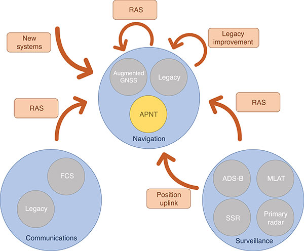
Proposed APNT solutions are generally sourced from the existing CNS environment. A common strategy is to use an aviation-certified signal not originally intended for navigation, which we have termed repurposed aviation signals (RAS). Other proposals include improving legacy systems, transmitting the ground-computed position to an aircraft, and creating new systems entirely. These sources of APNT are summarized in FIGURE 1 with explanations of the abbreviations to follow.
FIGURE 1. Sources of APNT for navigation. (Image: Weaver et al)
A natural candidate for APNT is the use of existing non-GNSS navigation infrastructure. Prior to GNSS, VOR beacons providing beacon-relative heading information and DME navaids supplying two-way range information were the primary navigation infrastructure. Improvement in DME avionics enabled tracking of multiple DME stations, providing a DME-only position solution referred to as DME/DME. Adding DME ground stations and upgrading existing hardware to increase accuracy and coverage of DME/DME positioning was therefore an attractive APNT option.
Another option sourced from the existing navigation infrastructure was to use RAS for positioning. One such RAS is that of the DME reply signal to a non-existent aircraft. By triggering DME responses in a desired fashion, aircraft can use the triggered responses for passive ranging without any change to the DME ground stations.
Communication systems for aviation are also undergoing modernization efforts. Future communication systems (FCS) are being developed to provide broadband communication capability between aircraft and controllers.
Surveillance is the domain of ground-based systems that determine the position of remote objects and is fundamental to allowing safe spacing of aircraft. Its origins reside in the development of primary radar, which was then complemented with secondary surveillance radar (SSR). Both primary radar and SSR use a rotating antenna to measure range and bearing to determine the location of the remote objects. Radar systems tend to be clustered around airports, limiting their area of coverage. To expand coverage in challenging terrain where radar is difficult to install, a technique known as multilateration is used, where a surveillance ground system can receive a signal from an aircraft and determine its position by comparing the time of arrival (TOA) of the signal between its ground stations. These systems were considered as a source of APNT by providing the aircraft position computed on the ground back to the aircraft via data uplink, but timely authentication and integrity concerns have stalled this approach in the United States.
Surveillance RAS for APNT. The other branch of surveillance-sourced APNT is by using RAS, and this is very relevant to the design of Mode N. The system providing many of the RAS for navigation is ADS-B. With this service, an aircraft broadcasts its GNSS-derived position (ADS-B Out) to ground-based stations and any aircraft capable of receiving ADS-B transmissions. ADS-B is an important part of airspace modernization strategies; it is mandated for aircraft operating in most U.S. airspace, with European mandates following suit. ADS-B ground stations, referred to as ground-based transceivers (GBT) or radio stations (ADS-B RS), collect ADS-B Out messages for use by air traffic operators. These ADS-B RS also provide their own transmissions for use by aircraft that can receive ADS-B broadcasts (ADS-B In capability) and include weather information, nearby air traffic and so on.
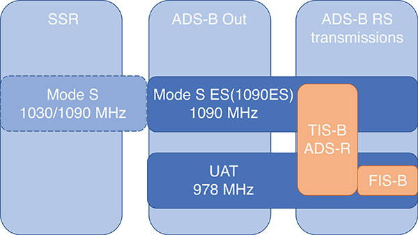
ADS-B can use different protocols to transmit its signals. The Mode S (S for selective) protocol was designed to allow SSR ground stations to selectively interrogate aircraft in their coverage area, reducing congestion on the reply frequency. The Mode S reply format consists of a four-pulse preamble and a data block containing either 56 or 112 information bits for the aircraft to provide information dependent on the interrogation received. Mode S is internationally standardized, and an extended format known as Mode S Extended Squitter was adopted for Automatic Dependent Surveillance Broadcast (ADS-B) services. Mode S Extended Squitter or 1090ES (as it’s transmitted exclusively on 1090 MHz) is also used by the ADS-B RS that rebroadcast ADS-B Out (ADS-R) and provide traffic information services (TIS-B) to nearby aircraft with ADS-B In capability.
Another protocol, used in the United States, is the Universal Access Transceiver (UAT) format. Like 1090ES, UAT is used by certain aircraft to transmit their ADS-B Out messages. Similarly, ADS-B RS transmits TIS-B and ADS-R messages with the UAT protocol; it also includes additional information that it transmits with the Flight Information Service – Broadcast (FIS-B). UAT signals are transmitted in the United States on an unused DME channel frequency of 978 MHz. FIGURE 2 summarizes the relationship between these surveillance signals and the services that use them.
FIGURE 2. Services using Mode S and UAT signal formats.(Image: Weaver et al)
Research investigating the ground-transmitted (ADS-B RS) 1090ES and UAT signals for ranging measurements greatly supports the assessment of Mode N presented here, as the Mode N system operates on a similar basis with a signal that blends characteristics of 1090ES and UAT.
Mode N Overview
Mode N (N for navigation) is a passive ranging system concept from DFS that seeks to provide APNT while reducing the spectrum congestion caused by existing aeronautical navigation and surveillance systems. The design includes the possibility for two-way and air-to-air ranging, but this overview focuses on the preferred passive mode of operation. It is designed around the Mode S format, which as mentioned, is used for SSR and ADS-B services. Despite early references to an SSR/N system, Mode N is not a new SSR mode but rather a new navigation system.
The basic concept is for Mode N ground stations to transmit on a single frequency signals that include ground station ID/coordinates, allowing aircraft with Mode N avionics to receive those signals and determine position in a similar manner to GNSS. As a single frequency is desired to minimize spectrum usage, the ground stations would space their transmissions apart to avoid intersystem interference. This scheme, known as time division multiple access (TDMA), would require information within the signal message on the scheduled time a ground station transmits, which the Mode N format allows.
Because Mode N shares many design aspects with Mode S, DME and other surveillance RAS, it is able to leverage previous APNT work for the benefit of its own analysis. Therefore, the overview of the design is described here relative to other APNT systems, as this is the basis of the preliminary performance assessment we present.
The Mode N Signal. The Mode N design proposes using the Mode S downlink signal format as the basis for its ranging signal to be used by the aircraft for passive position determination, with some key differences. The frequency channel on 1090 MHz is too congested to accommodate more signals; thus, the first difference is that Mode N intends to transmit on a different frequency. While the channel selection is still ongoing, unused DME channels have been identified as options for frequency allocation.
The second difference is the message content. As the Mode S downlink format transmits mainly aircraft-specific information, Mode N ground transmitters would instead populate their messages with information needed for passive ranging: ground station coordinates and time of transmission (TOT). The study of 1090ES messages (which also contain aircraft-specific information despite being transmitted by ground stations) as RAS required some special techniques to first identify which station was transmitting the message. The TOT is not present in 1090ES signals, but more importantly the time of transmission is not synchronized to any consistent reference. Aside from transmission frequency and message content, the Mode N signal design follows the Mode S downlink format (modulation, pulse shape and so on).
The Mode N signal also shares some aspects with the UAT signal, particularly the FIS-B segment. First, UAT is also transmitted in the United States on an unused DME channel. The FIS-B message, which provides weather information, transmits the ground station coordinates and information that can be used to estimate the TOT. Specifically, UAT messages are synced to UTC, and each ADS-B RS has a designated time slot within a one-second interval where it transmits its FIS-B message. This time slot is included in the message, and can be used to determine the TOT of the signal. Mode N is designed to work in this exact manner, minus the weather information. One crucial difference between UAT and the Mode N design is the type of modulation. Like Mode S, Mode N proposes using pulse-position-modulation (PPM) or on-off keying (OOK). The resulting wider bandwidth — estimated to be less than 4.6 MHz at –3dB — has better resistance to multipath, whereas UAT is frequency modulated to maintain a narrow bandwidth to avoid interference with DME and is more susceptible to multipath. Research on UAT signals for pseudoranging capability (also determined at a higher update rate than once per second) would be necessary for navigation, an important consideration for the final Mode N design.
Ground Infrastructure. The Mode N design, while based on RAS from the surveillance capability, requires new ground stations to transmit the Mode N signal. Requirements for the ground stations are that they provide adequate coverage to meet the requirements of an APNT system and that they are sufficiently synchronized in time. An initial time-synchronization scheme is the use of a radio frequency (RF) network consisting of the ground stations themselves, which requires radio line-of-sight of stations throughout the network. DFS performed a study and found that additional time-beacon stations would be necessary to maintain this RF time network, even though navigation coverage was provided using existing DME sites as hypothetical Mode N stations. Since these aspects of the design are still developing, the preliminary assessment we present assumes a network layout and time synchronization tolerance. As the Mode N design blends various CNS principles, a natural baseline design for the ground station locations consists of existing DME and surveillance sites in Germany. Using these locations for the ground stations enables computation of a horizontal dilution of precision (HDOP) at discrete locations throughout Germany. The assumed time synchronization is discussed further when developing a model of the Mode N ranging accuracy.
Avionics. An interesting aspect of the Mode N design is its proposed avionics unit. The Mode N avionics must be capable of receiving Mode N messages, which it can do with the existing DME antennas on aircraft. The Mode N avionics unit must then decode the messages for position determination. Its active mode for two-way and air-to-air ranging would require the Mode N avionics to transmit Mode N messages, again using the existing DME antenna.
Recognizing the continuing investment in the DME network by multiple countries, the Mode N avionics sensor is essentially built around a fully functional DME unit. This is intended to provide a seamless transition as Mode N stations are brought on line. The design of the avionics has little effect on the coverage assessment, aside from guaranteeing a minimum level of performance based on the current DME network, but is an important part of the implementation strategy. Furthermore, this blend of avionics has also been proposed for a unit compatible with DME and ADS-B (1090ES and UAT) signals.
Preliminary Coverage Assessment
Preliminary coverage assessments are a typical method to determine the feasibility of a proposed system to provide the required level of performance over a given area. A simple method of characterizing the position performance is in terms of the linear relationship between range error and DOP, where the range errors are assumed to be zero-mean, uncorrelated, and have identical distributions.
As the aircraft is assumed to have additional sensors for determining its altitude, HDOP is commonly used to characterize the expected horizontal position performance.
With range measurements, HDOP is a function of the transmitter geometry available to an aircraft at a given point. It is a straightforward computation to perform for a grid of points over the area of interest. The HDOP computation does depend on the type of range measurement, so passive (pseudo-) range, two-way range, and time difference of arrival (TDOA) measurements all have their corresponding DOP computation. Determining a model for the range error is less straightforward, and assessing the coverage potential of Mode N requires an estimation of the expected range error.
Modeling Mode N Range Accuracy. As Mode N is not an existing system, abundant quantities of real measurements are unavailable for empirically characterizing the range performance. However, since Mode N is heavily based on the Mode S signal format and functions similarly to the DME and UAT signals, which all exist and have been measured extensively, research investigating those signals can help derive the model for the Mode N range performance.
An alternate approach is to reference the standards for a specified performance level. For example, ICAO documentation specifies that the Airborne Collision Avoidance System (ACAS) logic use a zero-mean normal distribution range error model with a standard deviation of 50 feet, or about 15 meters. As ACAS also uses the Mode S signal format, this appears to be a reasonable source for the Mode N range error. However, since ACAS is an airborne two-way surveillance method, it does not exactly translate to a ground-based passive TDOA system such as Mode N. The 15-meter standard deviation is still useful, as it provides a check on the estimated Mode N accuracy. Other specifications suffer from similar drawbacks — Mode N does not directly apply to any single system. Thus, we apply the blended approach using previous APNT research.
The fundamental measurement for the passive ranging mode of Mode N is the TDOA between pairs of ground stations. This measurement is in seconds, and is translated to a range difference by using the speed of radio signal propagation in a vacuum. (See our conference paper for further details.)
Errors can be present in the TOA measurement, synchronization of the nominal TOT of the signals, and parsing of the time slot data field. The TOA measurement can have errors by inaccurate determination of the actual TOA due to noise or multipath and by the actual TOA differing from the nominal arrival time of the signal due to atmospheric delay. For terrestrial systems, propagation errors are considered to be dominated by multipath, so we don’t consider atmospheric effects here. Time synchronization errors are very important to the ranging accuracy, but it is assumed the time slot data field is parsed accurately. Other sources of error, such as inaccurate ground station coordinates, can affect the position error but have no effect on the range error. Additionally, the error originating from the change in aircraft position between reception of signals at ground stations is not considered in this article. The model of range accuracy can then be expressed as the root-sum-square (RSS) of the dominant individual error components.
We studied each error component in isolation, selecting the applicable APNT research to leverage based on the Mode N design aspect that most corresponds with that error.
Since the Mode N design also uses a pulsed signal, the evaluation of DME (specifically, DME/N) ranging performance is the starting point for estimating the TOA noise error. Part of the APNT effort was evaluating current DME performance, as it was thought it exceeded the specified performance in standards. A study found that current DME performance allowed a budgeted TOA error of 15 meters, 2σ.
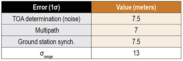
For the Mode N error model, a 7.5-meter error is an attractive option to choose as it is the average of two other sources and is the most recent. This value is a conservative estimate of the TOA accuracy for Mode N because the Mode N/S pulse shape is narrower than the DME pulse with a greater bandwidth, improving theoretical accuracy. For the preliminary coverage assessment, a conservative estimate is desired, because the actual TOA accuracy will vary over an area depending on transmitter distance — which impacts the level of signal noise. Note that the DME TOA errors are not divided by two as is done for the total DME error as they apply to a one-way TOA measurement.
After assessing the relevant studies, we modeled the multipath component of the error following that from Mode S as 7 meters, 1σ.
The final error component to estimate for Mode N is that of the synchronization of the ground stations. Based on the results from studies of the UAT signal and those from eLoran, we set a 15-meter maximum bias as a 2σ error component in the Mode N error model.
Our error analysis is summarized in TABLE 1.
TABLE 1. Predicted Mode N range accuracy. (Data: Weaver et al)
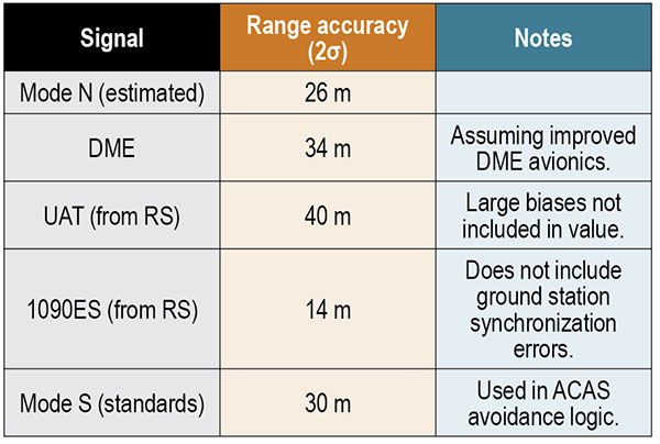
A total 2σ error for current DME performance of 92 meters has been established, which translates to 46 meters of range accuracy after dividing by two (since the DME signal is a two-way range). A substantial part of this error derives from the avionics bias, which is minimized for a “potential” DME error budget due to an assumed improved avionics performance. This results in a DME range 2σ error of 34 meters. We chose this value to compare as the effect of avionics has less of an impact in a passive ranging system such as Mode N.
Range performance for UAT signals was evaluated with measurements showing 20-meter (1σ) error when compared to GNSS truth, not including large biases attributed to ground station synchronization or processing errors. The 1090ES signals do not have an inherent ranging capability, so the TDOA measurement error of two ground station signals to one receiving station is difficult to measure. Instead, researchers have measured the differential TOA (DTOA) of one ground station signal received by two (GPS-synchronized) receiving stations to first identify which station transmitted the signal. When compared to the true DTOA based on ground station and receiving station coordinates, the measurements contained small biases around 10 meters with a standard deviation also less than 10 meters. Being DTOA measurements, these do not contain ground station synchronization errors, so the reported standard deviations correspond mostly with propagation and determining TOA. The 10-meter DTOA 1σ error can still be converted to a range error resulting in 14 meters (2σ). These results are summarized in TABLE 2.
TABLE 2. Comparison of Mode N with other APNT signals. (Data: Weaver et al)
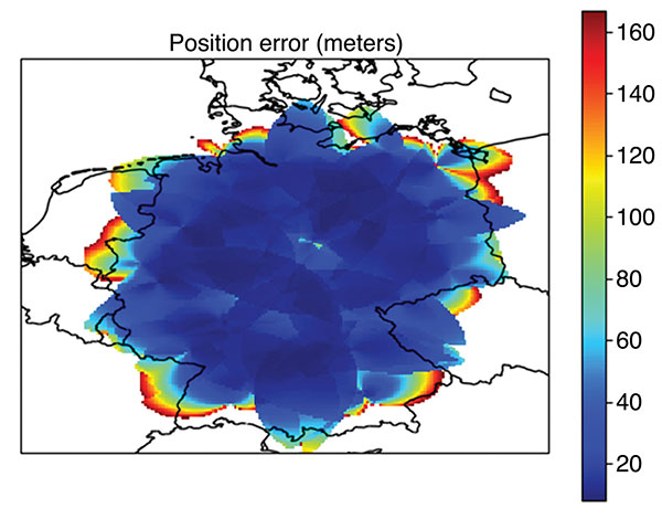
Coverage Assessment. With the estimated ranging accuracy, a preliminary coverage over Germany could now be assessed. Using the current 29 surveillance site locations in Germany and assuming that a minimum of three stations is necessary for positioning, the estimated position accuracy is shown in FIGURE 3.
FIGURE 3. Estimated position error (in meters) for aircraft within a 100 nautical mile coverage radius using existing surveillance sites as installation locations for Mode N ground stations. (Image: Weaver et al)
The coverage assessment used a “flat” Germany model with the estimated range accuracy from the preceding section (13 meters, 1σ). Atmospheric and terrain considerations were not applied in the assessment. It is important to note that this level of coverage would degrade at lower altitudes.
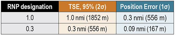
To determine whether this level of accuracy is sufficient for the airspace modernization efforts in Europe, the desired Required Navigation Performance (RNP) accuracy requirement must be examined. For RNP 1.0, where 1.0 refers to the required 95% or 2σ total system error (TSE) accuracy in nautical miles, the position error allocation is assumed to be 30% of the RNP/TSE value. The required position accuracy is shown in TABLE 3.
TABLE 3. RNP required horizontal position accuracy. (Data: Weaver et al)
From Figure 3, aircraft at altitudes within the service volume supported by a 100-nautical-mile coverage radius are capable of meeting the accuracy requirement for RNP 1.0 and 0.3 within most of Germany. Coverage along the border is unavailable as only German surveillance site locations were used.
Conclusions
Although our derivation of accuracy and the coverage assessment method we used made several simplifying assumptions, the results indicate that Mode N has the potential to be a feasible APNT system. To be a part of the modern airspace navigation infrastructure, additional accuracy requirements must also be met. The integrity requirement is harder to meet than accuracy, and requires either redundant information available to the aircraft for a receiver autonomous integrity monitoring-like algorithm or a ground-based monitoring/augmentation system. Perhaps the biggest challenge to implementing the Mode N infrastructure is maintaining an RF-based time synchronization network. Convincing aircraft operators to update their avionics is another challenge to Mode N implementation, although the inclusion of DME functionality in the Mode N avionics seeks to ease that transition.
DISCLAIMER
The views expressed herein are those of the authors and are not to be construed as official or reflecting the views of Deutsche Flugsicherung.
ACKNOWLEDGMENT
This article is based on the paper “An Overview of the Proposed Mode N System in the Context of Alternative Position, Navigation, and Timing (APNT) Development” presented at ION ITM 2021, the virtual 2021 International Technical Meeting of The Institute of Navigation, Jan. 25–28, 2021.
BRANDON WEAVER is a researcher at the German Aerospace Center (DLR) and works on alternative navigation systems.
GIANLUCA ZAMPIERI joined the Alternative Navigation Systems Group at DLR’s Institute for Communication and Navigation in 2019.
OKUARY OSECHAS leads the Alternative Navigation Systems Group in the Institute of Communications and Navigation at DLR.
SiTime Corp. has unveiled its Endura micro-electro-mechanical system (MEMS) timing solutions for aerospace and defense applications including precision GNSS, as well as field and satellite communications, avionics and space.
The Endura products are engineered to provide high performance in harsh conditions — severe shock, vibration and extreme temperature — that are routinely experienced in these applications.
SiTime offers customers 5 million possible part numbers that can be created from 17 programmable products.
“When exposed to high levels of shock, vibration, and extreme temperatures, legacy timing components have been prone to failure, degrading system performance and reliability,” said Piyush Sevalia, executive vice president of marketing. “To solve these problems, SiTime created an oscillator system of silicon MEMS, analog circuits, compensation algorithms, and advanced packaging, which is designed to outperform any other available timing solution in harsh environments.
“For example, Endura precision TCXOs deliver 4 parts per trillion per g (ppt/g) of acceleration sensitivity, which is 50 times better than legacy quartz-based solutions. With such performance, we believe that Endura will transform the oscillator landscape in aerospace and defense.”
Highlights of the company’s solutions include:
4 parts per trillion per g force of acceleration (50 times better than quartz)
Supports –55 degreesCelsius and +125 degrees Celsius operation
Key timing specifications conform to MIL-PRF-55310
Five million possible part numbers
Endura Super-TCXOs (temperature compensated oscillators) for use in high-speed communications and GNSS applications include:
SiT5146/SiT5147 – 1 to 220 MHz, ±0.5 to ±2.5 ppm, -40 degrees Celsius to +105 degrees Celsius
SiT5346/SiT5347 – 1 to 220 MHz, precision ±0.1 to ±0.25 ppm, -40 degrees Celsius to +105 degrees Celsius
SiT5348/SiT5349 – 1 to 220 MHz, ultra-precision ±0.05 ppm
SiTime’s portfolio of commercial off-the-shelf (COTS) Endura products spans six oscillator types and 17 products. All devices offer programmable options such as frequency, operating voltage and stability.
In addition, some devices offer specialized programmable features such as spread spectrum, pull-range, and differential output type.
Endura products are available with up to two grades of acceleration sensitivity, as low as 4 ppt/g (typical). This breadth of products provides customers with a large selection and the ability to configure each device for their application requirements.
Endura products are also designed for continuity of supply for long-life programs.
GE Aviation has introduced a new advanced avionics computer specifically built for military and commercial unmanned vehicles. This new computer provides an open architecture design that integrates vehicle management and advanced mission processing into a compact, lightweight design.
GE Aviation made the announcement at AUVSI Xponential, taking place April 29-May 2 in Chicago.
“Our customers have told us that they require an integrated vehicle and mission processing solution that is secure, rugged, low size, weight and power and capable of meeting the needs of demanding autonomous platforms,” said Alan Caslavka, president of avionics for GE Aviation. “This new system hits it out of the park in this regard and then builds from there in terms of bringing new capabilities to the next generation of unmanned systems.”
This new system incorporates the processing power required for mission functions such as sensor processing at the edge and hosting autonomy enabling algorithms and then also embeds an inertial/GPS package, software defined radio, datalink and an optional solid-state storage device.
Caslavka added, “The new system incorporates diverse processing that’s capable of performing safety critical and non-critical functions while bringing a new level of security to legacy and future platforms.”
The system integrates the functionality traditionally provided by up to six separate electronic units into a single package which drives out weight, power, and cost while meeting the security, exportability, ruggedness and processing needs of our customers.
GE’s advanced avionics computer has undergone flight testing and is in use by a number of military and civil customers. The computer incorporates a hardware and software open architecture approach that offers flexibility and scalability. This design also provides the capability to host GE, customer and third-party software applications to maximize its versatility.
Foxcom, a subsidiary of Global Invacom, has launched a solution that enables aircraft ground engineers to undertake 24/7 avionics testing of Inmarsat, Iridium and GPS satellite signals indoors.
The Hangar Repeater Solution enables engineers involved in maintenance, repair and overhaul (MRO) of aircraft to undertake testing 24/7 regardless of the weather, without having to move aircraft in and out of a hangar, as is the current practice.
The dedicated repeater greatly reduces aircraft-on-ground time, work hours and overall maintenance costs, providing a rapid return on investment.
While Inmarsat and Iridium satellite equipment has been deployed worldwide, its use was limited to outdoor, as building structures block satellite signals. Foxcom’s unique and all-inclusive repeater solution provides communication inside buildings or underground without the need for a direct line of sight to the sky. An existing Foxcom repeater can be easily upgraded to add Inmarsat compatibility.
Beyond the aviation sector, GPS, Inmarsat and Iridium repeaters can be deployed across a range of locations and industries, such as underground civil defence and military bunkers, oil rigs and ships and large buildings.
Foxcom launched its first range of repeaters in 2013. Established in 1993, Foxcom specializes in radio frequency over fiber equipment. It is a top supplier to satellite operators, broadcasters and integrators worldwide, with products that offer high performance, bandwidth and reliability.
A FreeFlight Systems SBAS/GNSS receiver has been selected to provide ADS-B position source information as a part of an upcoming ADS-B modification and compliance program for the United States Air Force HH-60G helicopter fleet.
Strategic Enterprise Solutions Corp. (SESC) of Warner Robins, Georgia, was awarded the modification program, which includes installation of the 1203C SBAS/GNSS receiver and the AN/APX-119 Mode S Extended Squitter transponder with Mode 5 capability to provide a complete ADS-B Out solution for more than 100 helicopters.
An HH-60 Pave Hawk helicopter lands in Afghanistan; a UH-60 Blackhawk is in the background. (Photo: U.S. Air Force photo/Senior Airman Brian Ferguson)
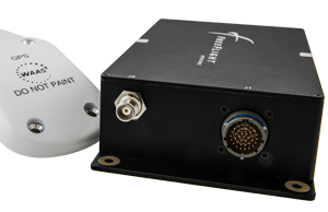
The FreeFlight Systems 1203C SBAS/GNSS receiver is a certified, high-integrity position source in a compact, lightweight package that was designed to be modular and able to be integrated with various other avionics.
The 1203C pairs seamlessly with certified Mode S Extended Squitter transponders for a fully rule-compliant ADS-B Out system, FreeFlight said.
More than a war hawk. The primary mission of the HH-60G Pave Hawk helicopter is to conduct day or night personnel recovery operations into hostile environments to recover isolated personnel during war.
The HH-60G is also tasked to perform military operations other than war, including civil search and rescue, medical evacuation, disaster response, humanitarian assistance, security cooperation/aviation advisory, NASA space flight support, and rescue command and control.
The 1203C in service. With several hundred 1203Cs in service across airline transport, military, business aviation and rotorcraft platforms, these receivers are known for their high performance, ease of installation, operational reliability and longevity, FreeFlight said.
The 1203C SBAS/GNSS receiver and antenna (Photo: FreeFlight Systems)
The 1203C can also serve as the approved position source for select manufacturers of TAWS/FMS, RNP and other NextGen applications, and allows customers to take advantage of the operational and safety benefits provided by the NextGen airspace transformation without the need for extensive and costly avionics upgrades.
With the ADS-B mandate now only 17 months away, aircraft operators need to prioritize ADS-B installations.
Significant portions of today’s airline, business, and military aircraft fleet will remain in service long after 2020, and in many cases an STC’d retrofit solution comprising of a transponder upgrade and the addition of a dedicated SBAS/GNSS receiver like the 1203C is the simplest and most cost-effective way to achieve mandate compliance, FreeFlight said.
Aspen Avionics and Sensurion Aerospace have entered a co-development partnership to bring certified avionics to the burgeoning UAS and unmanned air-taxi marketplace.
The companies are focusing on U.S. Federal Aviation Administration (FAA) certified autopilots, communications, navigation and surveillance systems for small, medium and large UAS, including future cargo and passenger carrying aircraft.
With revenue estimates for commercial drone operations exceeding $100B in the next 10 years, and the demand for UAS with certified avionics filling a large gap between hobby drones and military platforms, this partnership will create jobs and fill the void in commercial UAS avionics.
The current UAS operational environment needs to evolve to meet, what experts believe, is the next great global innovation — unmanned air-taxi and personal vehicles.
Initial product development from the team will include an autopilot/flight controller, FAA Technical Standard Order (TSO) authorized GPS/GNSS and surveillance systems, including ADS-B.
“The real winners in this partnership are the UAS users, system integrators and manufacturers,” said Aspen President and CEO John Uczekaj, a 30-year veteran of the certified avionics industry. “Our consumers demand adaptability and a certifiable pedigree that can help get them to market quickly, operate with an extreme level of safety and include innovative architectures that combine certified avionics with today’s flying drone service/IoT data platforms, and near future cargo movers and people haulers.”
“Our UAS customer’s return on investment calculations turn profitable most quickly when they can operate beyond visual line of sight,” said Sensurion CEO Captain Joe Burns. “What they are asking for are proven systems that do not cost a fortune, meet governing authority standards, are able to evolve with the pace of global digitization, and most importantly offer a safer integration path into our airspace. Our roadmap is clear. We are combining the talents, agility and pedigree from two industry leaders, to bring UAS consumers what they want, with a value proposition that puts safe drone technology to work across many industries.”
Becker Avionics Diversity Mode S Transponder with ADS-B certified.
Avionics technology provider Becker Avionics has received certification for the company’s BXT6500 family Mode S transponder, designed for the rigorous flying environment characteristic of helicopter operations.
Paired with a FreeFlight Systems’ 1203C SBAS/GNSS sensor, the remote-mounted solutions provide helicopter operators a complete and cost-effective way to equip with ADS-B Out for the upcoming Jan. 1, 2020, mandate.
The Becker BXT6500 family Mode S transponder is diversity-capable and available for installation on non-TCAS equipped aircraft. A non-diversity option is also available.
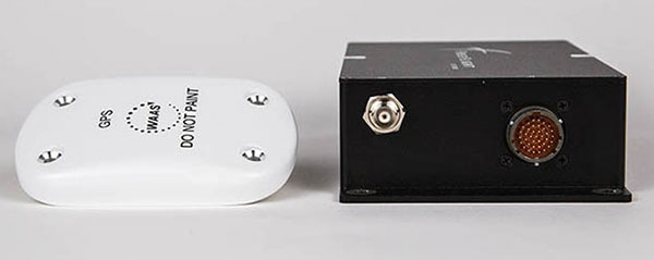
The FreeFlight SBAS/GNSS (WAAS/GPS) 1203C sensor.
In addition to providing clients with ADS-B compliance, the system features enhanced privacy settings that can disable both ADS-B and Mode S transmissions — a feature unique to the BXT6500 family.
“We are pleased to announce this new milestone in our transponder product line,” said Forrest Colliver, managing director. “This new system showcases how we tailor our compact, robust and durable avionics to our clients’ requirements in order to provide the best solution for where and how they fly.”
The system is a part of the company’s robust BXT6500 line of ADS-B Mode S transponders. Manufactured with a standard ARINC 429/743 output, this transponder easily integrates with the FreeFlight Systems Model 1203C SBAS/GNSS sensor for complete ADS-B Out compliance, and can be installed either as dual installation for primary transponder interrogations or as single install for a dedicated ADS-B transmission.
For more information, visit with Becker Avionics at booth C4935 and FreeFlight Systems at booth C1137 during HAI’s Heli-Expo happening this week in Las Vegas, Nevada.
The next generation of Europe’s satellite navigation overlay service, EGNOS, will combine use of GPS and Galileo signals to improve accuracy and robustness of navigation for air traffic and other uses where lives are at stake.
A contract was signed Jan. 26 at ESA’s technical centre in the Netherlands for the second generation of the European Geostationary Navigation Overlay Service, EGNOS V3, planned to enter service in 2025.
ESA Director of Navigation Paul Verhoef signs the EGNOS V3 contract Jan. 26 with Senior Vice President of Airbus Defence and Space, Mathilde Royer Germain. (Photo: ESA)
ESA Director of Navigation Paul Verhoef signed the contract with the senior vice president of Airbus Defence and Space, Mathilde Royer Germain, in the presence of senior managers of the European Global Navigation Satellite System Agency (GSA) and of the European Commission.
This improved version of the service will take advantage of in-operation Galileo signals as well as new frequencies from an improved class of GPS satellites. Use of the L5 second frequency will improve service robustness against errors and propagation delays caused by the ionosphere, an electrically active outer layer of Earth’s atmosphere.
“This will be the first such regional satellite augmentation systems worldwide to employ dual frequency, GPS and Galileo signals,” comments Didier Flament, overseeing EGNOS development for ESA.
For aircraft with the latest avionics, EGNOS V3 will be able to guide them accurately and safely down to Category 1, a 10 m Vertical Alert Limit (also called Cat1 Autoland capability), while also providing legacy users equipped with current avionics a more robust version of the current LPV200, or 35 m vertical limit vertical guidance service.
As well as improving services for civil aviation, the plan is to introduce new services for other sectors such as maritime navigation and rail, and extend service coverage from the European continent to link up seamlessly with other interoperable augmentation systems worldwide.
EGNOS is Europe’s other satellite navigation system, next to the global Galileo system. Comparable to the US WAAS, the Wide Area Augmentation System, and other regional augmentation systems in the rest of the world, EGNOS is an overlay system based on a network of ground stations and transponders on geostationary satellites. These stations gather data on the current accuracy of US GPS signals and embed correction data in the EGNOS signal, which is uplinked via geostationary satellites to EGNOS users.
The current EGNOS augments the accuracy of GPS signals across Europe and informs users of their current reliability level within six seconds. EGNOS belongs to a family of systems called Satellite Based Augmentation Systems (SBAS); the EGNOS V3 second generation will augment both GPS and Galileo.
Designed against global standards set by the International Civil Aviation Organisation, EGNOS began offering its Open Service for non-safety-of-life uses in October 2009. In March 2011 its Safety-of-Life Service became available for aircraft navigation.
Dozens of European airports are today employing EGNOS for vertical guidance approaches, as an economic alternative to ground-based infrastructure, like Instrument Landing Systems. It is estimated that that around 110 000 aircrafts worldwide are today equipped and using SBAS systems.
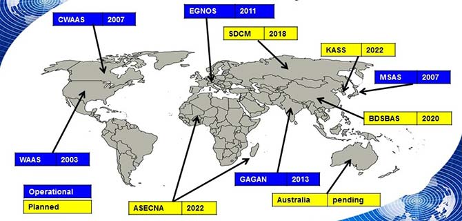
The development of satellite-based augmentation systems around the world is being coordinated in particular by the international SBAS Interoperability Working Group, which last week held its 33rd meeting at ESA’s centre in Madrid, chaired by ESA and the US Federal Avigation Authority, joined by current or planned service providers from Africa, Australia, Canada, China, India, Japan, Russia and South Korea.
Initiated by ESA in cooperation with the EU and Eurocontrol, the EGNOS Exploitation phase is managed by GSA and funded by the EU. ESA manages the EGNOS development under a working arrangement signed between GSA and ESA.
Rockwell Collins new generation GPS-4000-100 receiver
It’s still exceptionally difficult to qualify GNSS receivers for airborne use so there are only a few existing suppliers.
They include CMC Electronics with its line of OEM and enclosure products, Rockwell Collins with a new generation of airborne receivers just entering the market, Thales in Europe continuing to offer ARINC standard and multi-mode packaged receivers, Garmin still leading the panel-mount market for business aviation, Trimble/Ashtech continuing to promote its GPS/GLONASS airborne receiver, and newer entrants including Aspen/Accord with the NexNav GNSS line, and Avidyne with a home-grown embedded receiver in its flight management systems.
It’s been a while since we reviewed the status of certified airborne receivers, and I was prompted to do so by news that Rockwell Collins has a new generation of receiver which has just received Technical Standard Order (TSO) approval from FAA.
Rockwell Collins has fielded GPS products for 20+ years, and the GPS-4000S — with SBAS capability — has been fielded for more than 8 years, so parts obsolescence may become an issue. With new constellations, and with more countries implementing Space Based Augmentation Systems (SBAS), the 10 channel + 2 SBAS design needed an update. So Rockwell Collins undertook a bold step to develop and certify a radically new architecture for airborne applications — a software defined receiver.
Some Members of the Rockwell Collins Navigation Center of Excellence, in Melbourne FL (L-R); Jeremy Kazmierczak – Senior Systems Engineer; Eyal Wilamowski – GNSS Project Engineer; De Yao – Senior Electrical Engineer; Angelo Joseph – GNSS Architect, Technical Project Manager; and Principal Systems Engineer Vikram Malhotra – Senior Systems Engineer
A multi-frequency prototype first came together during two years of intense work by a couple of individuals, led by Angelo Joseph, an ex-NovAtel Aviation Group engineer with 15 years of GNSS design experience. When this proof-of-concept receiver demonstrated the required capability, a new GNSS receiver team was put together in Melbourne, Florida, to develop a fully qualified receiver, designed and built to stringent airborne standards.
Over the next six years, hardware was proven to meet performance, environmental, electrical, safety, high-integrity and reliability standards, and software was carefully developed and tested to meet the highest aviation qualification requirements — referred to as “Level A.”
In the process, a number of patents were generated — two have so far been approved in the United States:
Low-cost high integrity integrated multi-sensor precision navigation system, US 9513376 B1
Universal channel for location tracking system, US 9702979 B1
The universal-channel technique enables the new receiver to be configured to track any satellite navigation signal on all 14 + 4 SBAS channels (ultimately, this GNSS engine is anticipated to be able to track 100+ GNSS satellite signals), so the receiver is ready for when other constellations are approved for airborne navigation — for instance, European approval for Galileo use may be high on the list of new capabilities.
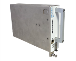
CMA-6024 GPS/SBAS/GBAS sensor
The new receiver is capable of LPV (localizer performance with vertical guidance) precision approaches to CAT I (down to ~200ft height in ~1/2 mile visibility). It features combined Required Navigation Performance (RNP) and approach capability, 10-Hz deviation output computations (20-Hz outputs), plug-and-play replacement for existing Rockwell Collins GPS receivers. It is Automatic Dependent Surveillance (ADS-B) compliant and has fast cold-start (<2 mins @ low SNR).
With production spooling up in Melbourne, Florida, it is available now for installation on business and regional aircraft.
An additional TSO application is underway to enable anticipated installations on Airbus and Boeing commercial transport aircraft. Work on the Rockwell Collins Next Generation Multi-Mode Receiver, the GLU-2100, is well advanced with an estimated availability at the end of this year.
In Europe, Thales markets the TopStar-C certified GNSS receiver solution for aircraft and helicopter navigation and approach, providing LPV, RNP and ADS-B, with Ground Based Augmentation System (GBAS) capability promised in the near future. Compliant with all these latest navigation functions, TopStar-C is available as both standard fit (installed as basic fit on a new aircraft) and for retrofit on aircraft and helicopters alike.
CMA-4124 GNSSA Precision Approach Receiver
The Thales Multi-Mode Receiver (MMR) is part of the TopFlight Line, which includes comprehensive solutions for communication, navigation and surveillance. The MMR is configured with GNSS landing system (GLS) and navigation capability, Instrument Landing System (ILS) and Microwave Landing System (MLS) receivers in one package.
ILS still provides Cat III precision landing system (effectively 700 ft visibility of the runway down to 50 ft) capability at a few key airports where severe weather can really disrupt scheduled airline operations. Nevertheless, ILS may encounters integrity problems due to FM interference and multipath reflection, which may degrade landing capabilities under low-visibility conditions — just when its most needed. MLS can provide Cat. III B (effectively 600 ft visibility of the runway down to 35 ft) landing alternative to ILS, but is fielded at very few airports.
Meanwhile, GLS is part of the international strategic plan to provide precision approach capability worldwide to an increasing number of runways. So airlines may soon have a number of precision-landing options at airports around the world — ILS, MLS or GLS — and the Thales MMR provides all three capabilities.
Garmin GTN-650 panel-mount Nav/Comm System
CMC Electronics introduced the CMA-6024 GPS Satellite Based Augmentation System and Ground Based Augmentation System (SBAS/GBAS) CAT-l/ll/lll Precision Approach Solution at the National Business Aircraft Association show in November 2016. CMC has been in the business of supplying certified GPS receivers for commercial air transport, business aviation and helicopter markets, either directly or through Honeywell and other partners for over 35 years — almost as long as GPS has been around! The CMC family of airborne receivers also has another connection with NovAtel — they were developed as a collaborative effort with NovAtel and incorporate patented Narrow Correlator signal tracking technology.
The CMA-6024 aviation GPS/SBAS/GBAS sensor has an embedded VHF Data Broadcast (VDB) receiver and an integrated GPS navigation sensor, is self-contained, and fully certified Precision Approach and navigation GBAS/GLS solution, certified to Design Assurance Level A.
Garmin GPS/Nav/Comm/Multi-Function Display.
The CMA-6024 provides a navigation solution that is fully compliant with Automatic Dependent Surveillance-Broadcast (ADS-B) and Required Navigation Performance (RNP). It comes with SBAS Localizer Performance/Localizer Performance with Vertical Guidance (LP/LPV) and GBAS Global Navigation Satellite System Landing System (GLS) GAST-C/D Precision Approach guidance for all aircraft. And it meets or exceeds the most stringent environmental requirements set out in RTCA/DO-160G, meeting additional requirements for specific aircraft, such as higher vibration levels for helicopters.
CMC’s family of GPS products includes the CMA-5024 GPS Landing System Sensor that meets the requirements for Instrument Flight Rules (IFR), civil certified GNSS, and also the CMA-4124 OEM GNSSA receiver card for embedded applications.
An SBAS/WAAS-certified, 15-channel GPS with 5-Hz outputs is embedded in the Garmin GTN-650 Nav/Comm unit, enabling GPS-guided LPV glide-path instrument approaches down to 200 ft. The system also includes VHF navigation capabilities, with a 200-channel VOR (VHF Omnidirectional Range) and ILS receiver for approaches with ILS localizer and glideslope. VOR navigation using the extensive ground VOR beacon system uses radial direction and distance to each VOR beacon within receiver range.
FreeFlight FMS/GPS
In addition, course deviation and roll steering outputs may be coupled to compatible autopilots so that IFR flight procedures may be flown automatically. And, when coupled with a flight display and compatible autopilot, the aircraft can fly fully coupled missed approaches, including heading legs as well as holds and search and rescue patterns.
In 2015, Aspen Avionics acquired Accord Technology, an Indian company which claims to have developed the first GPS WAAS airborne sensor to be authorized under US FAA TSO-C145c. These receivers are now marketed as the ‘NexNav’ product line. This receiver was apparently the first to comply with FAA AC20-165A for ADS-B GPS position source and is also sold as an OEM GPS SBAS card-level receiver authorized to TSO-204.
There are currently three NexNav receiver versions:
Mini (TSO-C145c SBAS Class Beta-1 only)
Max (TSO-C145c SBAS Class Beta -1, -2, -3) and
Micro-i GPS SBAS for TSO-C199 TABS for aircraft and experimental aircraft.
SBAS/GNSS (WAAS/GPS) 1201 Sensor
All NexNav GPS WAAS receivers are compatible with other SBAS systems around the world, including the European EGNOS, Japanese MSAS and Indian GAGAN.
FreeFlight also markets two GNSS sensors and a suite of aircraft avionics.
The 1203C sensor houses a high-performance 15-channel GPS engine with advanced interference protection and quick update rates, and is designed for business, regional, airline transport and heavy rotary-wing aircraft. The 1203C is certified to TSO-C145c and meets position source requirements for ADS-B and Required Navigation Performance (RNP) and other L-NAV operations. Another 1201 Sensor GNSS is specifically for General Aviation aircraft.
Bendix/King KSN 770 Flight Information Management System
Bendix/King GNSS navigation capability, like other General Aviation avionics suppliers, is often buried within a cockpit display system that serves to tune radios, and display information from weather radar, Enhanced Ground Proximity Warning System (EGPWS), XM Datalink Weather, Terrain awareness and warning System (TAWS) and Traffic Collision Avoidance System (TCAS).
Nevertheless, the KSN 770 features Wide Area Augmentation System (WAAS) and Localizer Performance with Vertical Guidance (LPV), and is specified as a “WAAS GPS enroute and approach navigation system.”
Ashtech, now a Trimble subsidiary, still lists the venerable GG12 OEM GPS/GLONASS receiver on its website, now somewhat updated to include SBAS as the GG12W.
Ashtech is careful to describe its OEM receiver as “capable of being qualified” within a TSO-ed FMS systems — presumably the approach has been to provide all the required qualification data to integrator companies, who include this receiver within the FMS as the GNSS navigation and approach receiver. The integrator then submits the Ashtech data to FAA to support their system TSO application.
Avidyne now integrates its own in-house-developed GNSS receiver into its line of cockpit mount FMS and related GNSS navigation and approach systems. And here there is another connection with Angelo Joseph — his work at Avidyne before he went to Rockwell Collins was to develop this Avidyne receiver to replace a bought-out embedded OEM GNSS receiver. The FMS has been certified using this new receiver to TSO-C146d — Stand-Alone Airborne Navigation Equipment using GPS augmented by WAAS, including Airborne Supplemental Navigation Equipment using the Global Positioning System (GPS) — Gamma 3.
Avidyne IFD540 display
There are clearly other companies who supply avionics for GA and Commercial Air Transport aircraft, but this article has attempted to capture a cross-section of GNSS offerings. Other notables include Sagem/Safran in France, Universal Avionics in Tucson, and quite possibly several others that we will no doubt hear about shortly!
As aviation agencies move towards adding the use of other constellations beyond GPS into approved, international navigation standards, there surely has to be significant change across the board for aviation as a whole as improved integrity and availability provide more options and capability. The existing avionics suppliers should be able to maintain market by offering more capability, and there might even be more opportunity for new entrants to come into the market with disruptive products, but for sure the future looks good for the industry.
A controlled radiation-pattern antenna can preserve GNSS positioning while providing at least an azimuth angle towards an interference source. If integrated with an attitude and heading reference system (AHRS), only a few lines of position pointing towards the RFI source could provide a fast indication of the probable ground location.
By Gerhard E. Berz, Pascal Barret, Brent Disselkoen, Michael Richard, Vincent Rocchia, Florence Jacolot, Todd Bigham and Okko F. Bleeker
GNSS is an essential enabler for many aviation applications that rely on either accurate position or time synchronization. While the idea of “sole means” GNSS is disappearing, it remains challenging to match the performance and coverage of GNSS with terrestrial systems. This is why aviation is working on Alternate Positioning, Navigation and Time (A-PNT) to cope with the potential for a wide-area GNSS outage. Current navigation aids are clearly part of this approach in the short term. We will continue to need a terrestrial capability for some time, but we don’t expect that it will support the same level of performance as GNSS. Even if we have back-up, we must be able to resolve GNSS outages efficiently.
Among principal GNSS vulnerabilities — constellation performance issues, space/solar weather and radio-frequency interference (RFI) — RFI is the one where observability on the ground is often limited. While the protection of radio services from interference is a state responsibility typically assigned to a telecommunications or other government agency, it is in the interest of an air navigation service provider (ANSP) to be able to request help and enforcement action from the telecommunications regulator in an efficient manner.
As a part of its contribution to Single European Sky ATM Research (SESAR, a collaborative project to improve European airspace and its air traffic management), Eurocontrol has developed an RFI Mitigation Plan as a guidance framework with the objective to maintain risks to GNSS and the associated operations at tolerable levels. The document will be published by ICAO in its GNSS Manual in the new 2017 edition.
MITIGATION PLAN
RFI can be a security issue. Consequently, a commonly used philosophy in the security domain was used in the mitigation plan: there are many potential threats, but not necessarily all of them translate into operationally relevant risks. Threats are thus sort of dormant risks, which, if left to develop unmitigated, could develop into risks to aviation. The mitigation process monitors threats, assesses risks, and then implements suitable mitigation to stop threats from developing into risks. Three successive stages have been identified where such barriers can be applied:
Prevent transmission of RFI, mostly through radio regulatory actions and coordination;
Prevent interruption of positioning and navigation capabilities in the presence of RFI. This is achieved at the avionics level by making sure receivers can tolerate some RFI as well as redundant capabilities;
If interruption cannot be avoided, ensure that other communication, navigation and surveillance capabilities provide continued safety while being able to detect, locate and eliminate an RFI source efficiently.
This third barrier is where flight inspection or other aerial work platforms can play a significant role. However, this role is not limited to risk mitigation. Aerial measurement capabilities can also play a role in threat monitoring by getting data on RFI emissions that are too weak to pose operational risks, and facilitate risk assessment by providing a reliable reference of the impact of such signals on an aircraft in flight.
FLIGHT INSPECTION
Similar to the subject of flight validation, airborne GNSS signal-in-space testing must not necessarily rely on traditional flight inspection capabilities. Other aerial work capabilities can be used, and it is hoped that, over time, data from regular aircraft operations and event recording systems can be used at least for threat-monitoring purposes. However, as soon as a significant RFI occurs, purpose-built aerial detection and localization capabilities are hard to beat. Given that aviation is carrying the risks related to RFI, and telecom regulators are unlikely to have such capabilities, this naturally points to the experience and resources of flight inspection aircraft and their crews.
Even if a significant amount of ground-based RFI sensors are available, local building shadowing can make it difficult to impossible to detect and locate an RFI emitter. Aircraft-provided data can be superior to ground data, and a rough aircraft-based localization can greatly increase efficiency of ground-based localization and source elimination efforts. Aerial RFI localization capabilities offer unique strengths in an overall cooperative process.
EVOLVING SIGNALS
GNSS manifests the transition from analog signals of conventional navigation aids to digital ones. A common characteristic of digital signals is their better use of a frequency channel by spreading the carrier energy such that distinct carrier or subcarrier tones become difficult to observe. Unfortunately, RFI sources have kept up with this, and now most commonly employ swept CW signals, easy to produce but still looking essentially like broadband signals. Many unintentional RFI sources also look like broadband.
Because GNSS is a multi-modal system not uniquely used by aviation, a new type of RFI threat is becoming more common: intentional RFI, which is not directed at aviation, but may nonetheless have an impact. Because there is no direct intent to harm aviation, the nature of these signals and RFI scenarios can become diverse and unpredictable. Furthermore, given the prevalent and ubiquitous nature of GNSS, the number of potential RFI threats is more significant and will evolve more dynamically than aviation capabilities.
A recent effort collecting GPS outage data reported by pilots revealed that a small but surprising number of outages that could potentially be linked to RFI occur on a regular basis, even during en-route operations in some limited regions of the world. For flight inspection, this implies it would be useful to increase the sensitivity of RFI source detection commensurate with the digital nature of GNSS and consistent with the power levels that can impact receivers.
Another particular challenge comes from the specification of an interference mask for GNSS. Other navigation systems do not have such a mask, or any kind of minimum signal-to-noise ratio standard. The mask represents a realistically achievable interference environment. It has been adopted as a global benchmark where receivers experiencing signals above the mask may not produce misleading information, but may stop operating.
However, in practice, little is known about by how much typical receivers exceed the minimum masks. Some tests have reported a margin as significant as 23 dB to CW and 10 dB to broadband signals. This means that an RFI which may not bother one type of receiver at all could be a significant problem for another, limiting the possibility to rely on observed receiver performance. It also implies that signal-in-space effects should be detectable at the low levels of the ICAO receiver RFI mask.
CRPA LOCALIZATION
For civil aviation as opposed to military operations, a CRPA could make sense provided that it outperforms current RFI localization methods at a reasonable price. In military applications, the exact location of the RFI source may be of a secondary nature, as long as desired signal tracking can be maintained.
However, by steering a null (negative gain) towards the angle of arrival of an undesired signal source, a line or sector of possible source positions can be obtained. In this case, the main objective would not be to null a deliberate interferer or jammer, but to obtain a bearing on the type of the interferer. The main scenario we worry about that leads to low-power events are those where aviation is not the desired target, such as a PPD. Unintentional cases can be a mix of high- or low-power cases. The use of a GNSS-specific antenna is expected to provide the required sensitivity, while being able to profit from the military off-the-shelf development. When further integrated with standard flight-inspection sensors such as an attitude and heading reference system (AHRS) and additional geolocation software, this approach has the potential to increase the reliability, accuracy and speed of geolocation while reducing operator effort and flying time. An additional potential benefit is the preservation of ownship position when flying into an area of significant RFI.
The suggested use of military technology brings with it the question on how such use could be authorized. CRPA antennas and associated antenna electronics manufactured in the United States fall under the International Traffic in Arms Regulation (ITAR). While this is a solvable but, nonetheless, cumbersome issue, the approach taken by this project was first to evaluate possible benefits from using a CRPA before worrying about the ITAR issue.
This study was conducted by Eurocontrol in the frame of a SESAR Project on GNSS, including a contract with Rockwell Collins for a feasibility study of the CRPA RFI localization concept. The French (DSNA/DTI) and U.S. FAA Flight Inspection service supported the project with expertise and in-kind contributions. The FAA conducted an overflight with a direction-finding-equipped aircraft for direct comparison between the CRPA approach and other, non-GNSS specific, commercial solutions.
TECHNOLOGY OPTIONS
Current, common GNSS CRPAs come in either 4- or 7-element variants. CRPAs always require antenna electronics for further processing of the RF inputs, and perform either nulling (steering negative gain towards RFI sources) or beamforming (steering positive gain towards GNSS satellites), or both. The most performant system is a 7-element CRPA in combination with digital beam-former antenna electronics. The 7-element CRPA has a diameter of 36 cm (14 inches), which is of some concern for installation on a typical flight-inspection aircraft such as the Beech King Air. But for a feasibility study, it makes sense to first evaluate the most-performing option. If there is unnecessary margin, the solution can be simplified afterwards.
A top-mounted solution on the airplane fuselage was retained due to experience with military anti-jam performance suggesting that RFI localization performance would be sufficient while retaining the benefit of stable ownship position. A key element of the assessment focused on how to best use aircraft banking to facilitate geo-localization.
As shown in Figure 1, the CRPA is connected to the Digital Integrated GPS Anti-Jam Receiver (DIGAR). As there is one RF cable per CRPA element, it is useful to install the DIGAR as close as possible to the CRPA. The standard military-production DIGAR contains not only the antenna electronics but also the receiver including baseband processing. For civil purposes, either a civil receiver would need to be integrated into the DIGAR or, alternatively, a single RF output is available to connect a standard civil GPS receiver. The DIGAR will also feed angle-of-arrival information into a direction-finder software.
Figure 1. System configuration. Source By Gerhard E. Berz, Pascal Barret, Brent Disselkoen, Michael Richard, Vincent Rocchia, Florence Jacolot, Todd Bigham and Okko F. Bleeker
The software provides angle-of-arrival information with respect to the antenna/aircraft reference frame. To provide a geolocation capability, this must be combined with ownship position and aircraft attitude. As most flight inspection aircraft are equipped with an AHRS, this is not expected to be a problem. Project resources did not permit full integration, so testing was done using the direction-finder display only. The AHRS would need to provide 10–50 Hz updates with an error of not more than ±2 degrees.
Figure 2 shows an example of the direction-finder output. Lighter areas show where the antenna electronics produce negative gain, while darker areas represent stronger positive gain. The red dot indicates a potential interferer has been identified. Source location is at about 280 degrees of azimuth with respect to aircraft nose.
Figure 2. Excerpt from direction finder polar display of RFI signal angle of arrival. Source By Gerhard E. Berz, Pascal Barret, Brent Disselkoen, Michael Richard, Vincent Rocchia, Florence Jacolot, Todd Bigham and Okko F. Bleeker
Correct detection probability will depend on the sensitivity threshold and associated false detection probability being considered acceptable. A visual localization may still be possible at carrier-to-noise density ratios (C/N0) below those needed to produce the red dot here, especially if the visible ambiguity can be removed through some aircraft maneuvering. It can be inferred from the system description that once the full integration is accomplished, the provision of a direct output using only a few lines of position to find a probable RFI source location in terms of approximate lat/long coordinates should be straightforward.
SIMULATOR TESTING
A well-calibrated simulator capable of feeding the seven RF inputs was used to assess detection performance for different flight patterns near an RFI source. The tested patterns include a rectangular, a circular and an oscillating, S-shaped trigger-and-hunt trajectory. A variety of different encounter scenarios in terms of power levels and free space path loss were tested. Power levels were adjusted to produce a 1-dB reduction in the C/N0. Both a continuous wave (CW) interferer at the L1 center frequency and a broadband (BB) interferer were simulated (using a 20-MHz-wide PSK signal). Figure 3 shows an example of achieved detection accuracies in both azimuth and elevation angle.
Figure 3. Example result of angular detection performance. Source By Gerhard E. Berz, Pascal Barret, Brent Disselkoen, Michael Richard, Vincent Rocchia, Florence Jacolot, Todd Bigham and Okko F. Bleeker
While there is a strong peak within ±10 degrees of azimuth, there are also significant outliers. For the elevation (note the normalized scale), however, the main peak is thinner with even stronger sidelobes. Due to the installation of the antenna on top of the aircraft fuselage, the simulation results indicate that the elevation angle output is not very useful for detection. The time series result for the azimuth is given in Figure 4, where it can be seen that there are many good detection matches but also some “sympathetic nulls” that move in the opposite direction of the ground track truth reference (circled in grey). It is expected that with additional software processing, these sympathetic nulls can be filtered out.
Figure 4. Azimuth Time Series Result Corresponding to Figure 3. Source By Gerhard E. Berz, Pascal Barret, Brent Disselkoen, Michael Richard, Vincent Rocchia, Florence Jacolot, Todd Bigham and Okko F. Bleeker
For all tested scenarios (assuming additional filtering), azimuth detection capability was better than ±10 degrees (one standard deviation), and in some cases as accurate as ±2 degrees. There was no significant difference between CW and BB results. As could be expected, simulated aircraft banking significantly improved detection capability. Consequently, the use of orbits seems to be the best search strategy. The simulator testing used a figure-eight pattern with one of the orbits passing over the interference source.
LIVE-SKY VAN TESTING
Rockwell Collins has an authorization to broadcast RFI test signals at the GNSS L2 frequency. Previous work showed that the results at L2 can be applied equally to L1. Figure 5 shows the test area, including a –100-dBm signal level boundary. The interferer was installed on a tripod and fed by a signal generator using a normal GPS fixed radiation pattern antenna (FRPA).
Figure 5. Live-sky test area. Source By Gerhard E. Berz, Pascal Barret, Brent Disselkoen, Michael Richard, Vincent Rocchia, Florence Jacolot, Todd Bigham and Okko F. Bleeker
Locations B and C were used to both calibrate the RFI level and as check points for the van trajectory. The test van included a fixture that allowed a tilting of the CRPA by 30 degrees from zenith to either side. Figure 6 shows a schematic of the tilt fixture. It can be seen that this set up creates a realistic RFI path that arrives with an elevation slightly below the horizon at the unit under test. Two sets of tests were performed: one where the van drove straight into or out of the area of interference to determine overall equipment sensitivity, and varied paths to quantify angular detection performance. Again, both CW and BB RFI signals were evaluated.
Figure 6. CRPA with tilt fixture. Source By Gerhard E. Berz, Pascal Barret, Brent Disselkoen, Michael Richard, Vincent Rocchia, Florence Jacolot, Todd Bigham and Okko F. Bleeker
Not surprisingly, elevation angle results turned out not to be very reliable given the below horizon signal path. But azimuth errors were slightly greater than obtained during the wavefront simulator testing (±12 degrees, one sigma). This can be attributed to both multipath and a less accurate heading truth reference. Taking these additional factors into account, the results are very consistent. Tilting the antenna by 30 degrees towards the RFI source significantly improves azimuth resolution (to about ±8 degrees) while also reducing sympathetic nulls. When the tilted antenna points away from the RFI source path, azimuth accuracy will decrease, which is considered helpful in avoiding false detections.
Summary. Even if a good bit of integration work remains necessary to produce a production-ready system for flight inspection or other similar aircraft, the approach shows promise. Further testing, especially using an actual aircraft installation, is recommended. Installation of a 7-element CRPA will be challenging on a typical Beech King Air, but possible. Antenna calibration requirements are expected to be manageable with a standard network analyzer. To avoid further complications with export regulations, the use of a separate civil GNSS receiver is recommended. The overall system is, at this stage, still on the costly side.
While a 4-element CRPA could be used, this was estimated to double or triple angular azimuth detection errors and reduce the detection distance, and consequently not likely to be worth the additional cost. While smaller 7-element CRPAs than the one used are available, their performance would need to be assessed.
For a top-mounted CRPA, aircraft banking is essential to ensure good performance. This could increase the amount of airspace required for detection and lead to operational complications. Furthermore, since the aim is to increase detection sensitivity to geo-locate weak power sources such as personal privacy devices, maintaining ownship position is not that critical, as it can be managed by maintaining an appropriate distance from the RFI source if needed. Consequently, both DSNA and FAA recommend using a bottom-mounted CRPA. In addition to adding 10 dB of detection sensitivity on average and reducing the need for maneuvering, it may restore the utility of the elevation output, thereby potentially further reducing search time. Either way, it will be useful for equipped aircraft to have alternate positioning capabilities to GNSS both for aircraft guidance and truth reference systems.
The system required a 15-dB stronger signal to transition from detection to localization. However, this is dependent on the accepted false-alarm rate. A tunable procedure can be envisaged where the software accepts a higher false-alarm rate at first to maximize search capability and moving to a lower alarm rate to confirm suspected RFI source locations later. Both the potential of the additional filtering software and any human-machine interface aspects would need to be further evaluated.
GENERIC CAPABILITIES
The two common options for in-flight detection of RFI sources in any relevant frequency band are the use of either a spectrum analyzer or, if available, a direction finder. The spectrum analyzer approach depends on connection to a suitable antenna, preferably with some directionality. In this way, the aircraft can be maneuvered to point the antenna either towards or away from the RFI source. Normally there is very little directivity, making this a challenging search. A direction finder is a significant improvement. Figure 7 shows the L-band antenna array used by a DF-4400 as installed on the bottom of the aircraft.
Figure 7. CRPA with tilt fixture. Source By Gerhard E. Berz, Pascal Barret, Brent Disselkoen, Michael Richard, Vincent Rocchia, Florence Jacolot, Todd Bigham and Okko F. Bleeker
Newer generation spectrum analyzers with a good GNSS-specific pre-amplifier, using digital sampling with a fast A/D converter, could provide useful capability. However, the subject is beyond the scope of this discussion, and we focus here on comparing the CRPA approach with a standard direction finder.
The FAA Flight Inspection service conducted complementary flights during the Rockwell Collins live-sky van testing. The flights included orbits and a direct overflight of the RFI source. This was complemented by additional laboratory calibration to ensure that results could be compared. The sensitivity results of the CRPA approach are more meaningful in comparison with a generic direction-finder capability. Since test data is only available for a top-mounted CRPA, the comparisons here are made for the preferred bottom-mounted CRPA using engineering estimation.
The key finding was that while direction-finding capability was quite comparable between the CRPA- system and the DF-4400 for CW, the CRPA-system outperforms the DF-4400 by a significant margin when encountering broadband signals. This is considered to be a significant improvement given the expected nature of RFI sources. During the FAA overflight, the aircraft did not manage to detect the broadband signal. Consequently, the values given here are reconstructed from laboratory analysis. Table 1 compares the estimated achievable sensitivities.
Table 1. Comparison of direction-finding sensitivity. Source By Gerhard E. Berz, Pascal Barret, Brent Disselkoen, Michael Richard, Vincent Rocchia, Florence Jacolot, Todd Bigham and Okko F. Bleeker
In view of the limitations of the data analysis performed, these values must be interpreted with caution. In general, we can conclude that the direction-finding sensitivity of the CRPA system is relatively insensitive to the encountered modulation of the RFI signal, and that the bottom-mounted CRPA system outperforms the DF-4400 system by a small margin in the CW case and by a large margin in the broadband case. How many additional dBs can be gained by both approaches through further optimizations is for future analysis. The performance improvement of the CRPA system does come at a cost, as could be expected.
DETECTION
Before the search for an RFI source can begin, it must be detected. Normally it should be easier to detect an RFI source than to locate it, since direction-finding requires a certain signal strength to obtain bearing information. However, given the directionality of DF arrays, this may not necessarily be true. Another potential factor is the reliance on a spectrum analyzer to detect RFI, which may not achieve the corresponding noise floor, especially when using a broad scan across a wide frequency range. The direction-finder system needs about a 15-dB difference between detection and localization ability.
Figure 8 shows the detection ranges for the top-mounted CRPA system for a given ground-based emitter while the aircraft altitude is assumed at 2000-ft AGL. The bottom mounted system would improve the minimum detection threshold further. Given that 15 dB can translate into a significant difference in free space path loss distance, concepts for efficient direction finding once an RFI source is detected deserve further attention.
Figure 8. Detection ranges for top-mounted CRPA system. Source By Gerhard E. Berz, Pascal Barret, Brent Disselkoen, Michael Richard, Vincent Rocchia, Florence Jacolot, Todd Bigham and Okko F. Bleeker
HUMAN FACTORS
During the FAA overflight, the broadband RFI couldn’t be detected by either the spectrum analyzer in use or the DF-4400. Part of the challenge was using the right equipment settings. For the DF-4400, it was found that best performance could be obtained for detecting broadband RFI when using the FM wide mode of demodulation. Similar findings were obtained for the use of the spectrum analyzer, where specific skills are necessary to use the equipment to its fullest capability. Similar issues are expected when having to interpret the display of a CRPA-based system. This means that regardless of the RFI source geo-location approach used, specific training should ensure that aircraft operators have the greatest chance of success in finding RFI sources.
CONCLUSIONS
An approach using a CRPA antenna, electronics and processing software proved superior to current, generic direction-finding capabilities, especially with respect to broadband signals. Maintaining ownship position in the presence of RFI is a secondary objective when looking for the expected weak signal sources, and the use of a bottom-mounted CRPA system is preferred. Additional filtering to eliminate sympathetic nulls and other issues require further investigation.
Significant benefit derives from employing aerial work aircraft in cooperation with ground-based capabilities. We recommend that equipment manufacturers further study all aspects of GNSS RFI geo-location and improve their capabilities. Such capabilities are expected to limit the exposure time to RFI cases and allow a more efficient deployment of ground-based spectrum enforcement resources. These studies should include the improvement of detection and localization equipment, and the development of corresponding operational procedures for flight crews.
ACKNOWLEDGMENTS
The Eurocontrol-funded contract with Rockwell Collins is part of the Eurocontrol contribution to SESAR Project 15.3.4, GNSS Baseline and the GNSS RFI Vulnerability Mitigation Task.
Rockwell Collins provided the DIGAR and Direction Finder Software.
This article is based on a paper presented at ION-GNSS+ 2016.
Disclaimer. This article does not contain any official Eurocontrol, SESAR, FAA or DSNA position or policy. It does not constitute any endorsement of a particular product, or a statement of any kind relating to any future procurement activity.
GERHARD BERZ and PASCAL BARRET work at Eurocontrol, Belgium; VINCENT ROCCHIA and FLORENCE JACOLOT with Direction des Services de la Navigation Aerienne, France; BRENT DISSELKOEN and MICHAEL RICHARD at Rockwell Colins, U.S; Okko F. Bleeker with OFBConsult System Engineering, the Netherlands; and TODD BINGHAM with the U.S. Federal Aviation Administration.