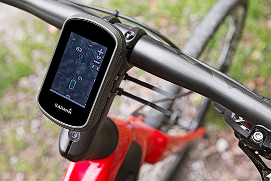
The Garmin eTrex can be mounted on bicycles, boats, ATVs or in the car.
Garmin International this summer is releasing the eTrex Touch 25, 35 and 35t, adding new touchscreen models to its line of outdoor handhelds.
The eTrex Touch series has a completely updated user interface, improving the ease-of-use of the device, as well as a 2.6-inch capacitive touchscreen display, the largest display that’s ever been put on an eTrex device. The eTrex Touch series also features new activity profiles for easy-to-use navigation for multiple activities and an enhanced track manager to easily start and stop recording.
The new eTrex Touch series has a high-sensitivity, WAAS-enabled GPS receiver with GLONASS support and HotFix satellite prediction to locate users’ position quickly and precisely, even in heavy cover and deep canyons.All units in the eTrex Touch series have a built-in 3-axis tilt-compensated electronic compass, which gives directional information even when standing still. The eTrex 35 and 35t also have a barometric altimeter to get more accurate altitude, elevation and climb information, as well as indications of pending weather changes.
The eTrex Touch 25, 35 and 35t are compatible with an array of mounts that are easy to use on bicycles, boats, ATVs or in the car, and offer a long-lasting 16-hour battery life, and a rugged ergonomic design to withstand the elements.
The eTrex Touch series integrates a variety of new activity profiles. The device remembers how each profile is set up to each activity, and will set it up for users the same way every time, making it comfortable, quick and intuitive to use the same device for entirely different purposes. No matter if users are out rock climbing, hiking, hunting, cycling, geocaching or fishing, with an eTrex Touch, switching between activities is easier than ever, even if they’re done all in one afternoon.
The eTrex Touch series comes preloaded with a worldwide shaded relief basemap, 4 GB of internal memory on the 25 and 35 models and 8 GB of internal memory on the 35t. The eTrex 35t also comes preloaded with TOPO U.S. 100K. With the built-in microSD card slot, users can install even more maps, like HuntView to see public and private land data while hunting, BirdsEye Satellite Imagery or TOPO U.S. 24K. All models come preloaded with 250,000 geocaches from Geocaching.com, so right out of the box users can start their geocaching adventure virtually anywhere in the world.
The eTrex 35 and 35t incorporate wireless ANT+ connectivity to accessory sensors like heart rate monitors, the Tempe temperature sensor, Chirp geocaching beacon, or the cycling speed sensors and cadence sensors. The eTrex 35 and 35t can also act as a wireless remote control for the VIRB line of action cameras. The eTrex 35 and 35t can connect via Bluetooth to compatible smartphones to receive smart notifications and stay connected out on the trail, but keep their phone safely packed away from the elements. Additionally, these units are compatible with the the Garmin Connect mobile app, for features such as LiveTrack. With LiveTrack, users can pair their device with the app, and invite friends and family to follow their activity in real time. This provides peace of mind, especially if users are alone.
The eTrex Touch 25 will have a suggested retail price of $249.99, the eTrex Touch 35 will have a suggested retail price of $299.99 and the eTrex Touch 35t will have a suggested retail price of $349.99.
Antenova announces its first antenna for consumer applications — the tiny Weii 2.4-GHz ceramic antenna. Measuring 1 mm x 0.5 mm x 0.5 mm, the company believes the Weii could be the smallest antenna in the world.
The new Weii miniature ceramic antenna is designed for 2.4-GHz, Bluetooth, Wi-Fi, Zigbee and industrial, scientific and medical (ISM) applications.
While all of Antenova’s antennas and antenna module products are small surface mounted devices, this antenna is the smallest that Antenova has created so far. It is designed specifically for the consumer, Internet of Things (IoT) and machine-to-machine (M2M) markets.
Colin Newman, Antenova’s director and vice president of sales, explains how Antenova has miniaturized the antenna. “Ceramic antennas offer low dielectric losses and high isolation. Our engineers have used this technology to greatly reduce the antenna volume without sacrificing performance. The challenge in building antennas for today’s small consumer devices is to achieve high isolation and frequency selectivity while maintaining good efficiency. This antenna is resistant to detuning from environmental effects, and combining this with its ultra-small size, makes it ideal for today’s wearable products.”
The Weii is an omni-directional, surface-mount device (SMD) mounted dielectric antenna that can be used to add wireless connectivity to any small electronic device, such as wearables, headsets, medical devices, personal navigation devices, dongles and sensors.
A ceramic antenna offers several advantages for these emerging applications. Its tiny footprint is designed for the new, scaled-down printed circuit boards (PCBs) that are being developed for consumer devices in M2M. It offers a highly efficient antenna that is powerful over indoor ranges, and that performs well when sited close to the human body, Antenova said.
Antenova says it takes a unique approach to the design of antennas, which it calls “Design For Integration” (DFI). Because the antennas are always embedded within a customer’s design, the successful operation of the customer’s device depends upon obtaining the correct performance from the antenna when it is placed on the PCB; therefore, Antenova is designing its antennas with this difficult RF integration in mind.
The Weii is designed to be easily integrated into all kinds of PCB designs and various ground plane sizes — it has been engineered so that it can simply be dropped into the design, using CAD footprint files, which are provided free of charge. To ensure that customers can harness the antenna successfully and achieve the optimal performance of the antenna, Antenova provides engineering assistance along with advice on RF design layout and the integration of the antenna, and customer support.
The antennas are available through distributors worldwide. See www.antenova-m2m.com for more details, or to request a sample board for the Weii antenna.
InvenSense Inc. is making available its InvenSense Positioning Library (IPL) software, designed to provide sensor-assisted positioning in places where GNSS alone cannot provide desired accuracy. Invensense is a provider of intelligent sensor system on chip for motion and sound in consumer electronic devices.
InvenSense made the announcement at Mobile World Congress, taking place in Barcelona, Spain March 2-5.
The IPL incorporates advancements in sensor-assisted positioning algorithms that allow use of inertial sensors to improve GNSS positioning in urban areas where satellite signals are either blocked or distorted by multipath, enabling continuous location availability while driving in underground parking lots, tunnels, or walking in urban canyons. The IPL enables continuous and accurate position, velocity and orientation in challenging operating environments.
These sensor-assisted positioning algorithms have been designed to operate under normal pedestrian and driving use without restrictions on the device orientation. Supported pedestrian use includes handheld, hand swinging, in pocket, call mode and belt holster. The algorithms also allow any use within the vehicle, such as in cradle, cup holder or simply left on a seat. The software was designed in a way to maximize accuracy and minimize constraints on the user.
The IPL is designed to operate with an IMU and GNSS receiver as minimum hardware. Integration with a magnetometer, barometer, and vehicle speed sensor is also available, which provides additional heading integrity as well as height and velocity accuracy for sensor-assisted positioning.
IPL is designed for smartphones using Android, iOS, Windows and general Linux operating systems and has already started shipping commercially. The underlying navigation technology comes from years of development at Trusted Positioning Inc., which was acquired by InvenSense this past summer.
“With more consumers using their smartphones for turn-by-turn navigation on foot or in vehicle, one of the most frustrating user experience issues is losing your GPS (GNSS) signal in an unfamiliar location or being re-routed erroneously due to multipath errors,” said Ali Foughi, vice president of Marketing and Business Development at InvenSense. “With IPL technology, high-accuracy location guidance is always available and provides smartphone OEMs with a differentiated user experience and consumers with a more reliable navigation solution.”
The InvenSense Positioning Library is available immediately.
InvenSense is exhibiting in booth #D61 in Hall 7 at Mobile World Congress.
A new module produced by a Chinese company combines GPS and BeiDou for civilian positioning, especially for automobiles. The module has been in development for years, and offers improved accuracy and reliability, according to its makers.
“GPS is a single-mode application. But we what are offering with our new module now is a system that can combine Beidou and GPS services, so that the accuracy and reliability can be improved,” Lin Hongzheng, China Electronics Tech. Group Corporation, told CCTV.
The module is expected to improve accuracy to better than one meter, which is now achievable by the current BeiDou system, according to the module’s developers. Ground stations would improve the accuracy even further. “Hopefully, it will be able to position vehicles in different lanes of a road,” said Hu Jinmin, Shenzhen Road Rover Technology.
Pricing has always been a struggle for Beidou hardware, CCTV said. The market price of the new module has come down to less than 30 yuan, or US$5, similar to that of a GPS module.
“This year, from modules to end products, the Beidou system is ready for massive production and ready to compete in the market,” Hongzheng told CCTV.
ION GNSS+, sponsored by The Institute of Navigation, is considered the world’s largest technical meeting and showcase of GNSS technology, products and services. This year’s conference takes place September 8-12 at the Tampa Convention Center in Tampa, Florida.
ION GNSS+ will bring together international leaders in GNSS and related positioning, navigation and timing fields to present new research, introduce new technologies, discuss current policy, demonstrate products and exchange ideas.
Pre-conference events held Monday and Tuesday, September 8-9, include tutorials and the CGSIC meeting. The conference itself kicks off Tuesday with the plenary session, held 6:30-8:30 p.m.
This year, the plenary speaker is Tristan Gooley, navigator and explorer, who will discuss “The Wonderful World of Natural Navigation.” Gooley has led expeditions in five continents, climbed mountains in Europe, Africa and Asia, sailed small boats across oceans and piloted small aircrafts to Africa and the Arctic. He has walked with and studies the methods of the Tuareg, Bedouin and Dayak in some of the remotest regions on Earth. Gooley will describe how his love of the subject grew over time and explains how he learned to find his way using the sun, moon, stars, weather, plants and animals. He has used natural navigation in the Sahara desert, in jungles, on ice, on oceans and in the English countryside. He will explain how these ancient techniques can be used by anyone willing to try something new and how natural navigation can enrich all journeys, large or small.
Gooley’s talk will be followed by Panel Discussion Lightning Talks moderated by GPS World Publisher Alan Cameron. Presenters include Dr. John Betz, The MITRE Corporation; Didier Faivre, European Space Agency, France; Dr. Frank van Diggelen, Broadcom; Glen Gibbons, Inside GNSS; Oscar Pozzobon, QASCOM S.R.L., Italy; Dr. Frank van Graas, Ohio University; Dr. Todd Humphreys, The University of Texas at Austin; Dr. Dorota Grejner-Brzezinska, The Ohio State University; and Dr. Didier Flament, European Space Agency, France.
Technical sessions will be held Wednesday, Thursday and Friday. This year, a new commercial track has been added.
This integrated circuit supports simultaneous reception and processing of the GPS L1/L5, Galileo E1/E5a, and GLONASS G1 signals with 40 tracking channels. The dual-band analog RF front-end is integrated on the same mixed-signal chip as the baseband hardware, including an embedded processor to close the tracking loops: overall, a compact, low-power, and low-cost solution.
By Fabio Garzia, Stefan Köhler, Santiago Urquijo, Philipp Neumaier,Jörn Driesen, Sybille Haas, Thomas Leineweber, Tao Zhang, Sascha Krause, Frank Henkel,Alexander Rügamer, Matthias Overbeck, and Günther Rohmer
Multi-constellation multi-band global navigation satellite system (GNSS) receivers can efficiently exploit the advantages derived from the modernization of existing GNSS constellations, such as GPS and GLONASS, as well as from the launch of new ones like Galileo and BeiDou. Utilizing multiple systems can significantly improve the availability of a navigation solution in urban canyons and heavily shadowed areas. Increased satellite availability also guarantees higher measurement redundancy and improved reliability. Moreover, the excellent inherent noise and multipath mitigation capabilities of the new and modernized wideband signals in the L5/E5a band, combined with the ionosphere error mitigation given by frequency diversity, significantly improves the accuracy in both measurement and position domains.
Still, most commercial fully-integrated single-chip mass market GNSS receivers use only a single-frequency band for their positioning, velocity, time (PVT) solution: either GPS L1 C/A or Galileo E1 and GLONASS G1. For example, the Teseo chips are single-chip solutions that support multiple constellations but only on one frequency band. This approach reduces design costs and enables the lowest consumption of power, but neglects the advantages of wideband signal processing – which offers increased robustness thanks to two simultaneous frequency band receptions and the capability of mitigating the ionosphere error.
Another approach for realizing multi-constellation multi-frequency solutions is to combine different chips for the analog front-end and the digital baseband. One fully integrated single-chip analog multi-band front-end for the simultaneous reception of GPS L1/L5, Galileo E1/E5, and GLONASS has been presented. However, this chip included only the front-end and requires an additional, separate digital-baseband solution.
The purpose of the NAPA project (NAvigation chip for Pedestrian navigation and higher precision Applications) is to close this gap by providing a fully integrated, compact, low-power, and low-cost solution in which the analog and digital parts of the GNSS receiver are integrated together on the same chip. The NAPA receiver offers all the advantages of multi-constellation reception with additional dual-frequency support.
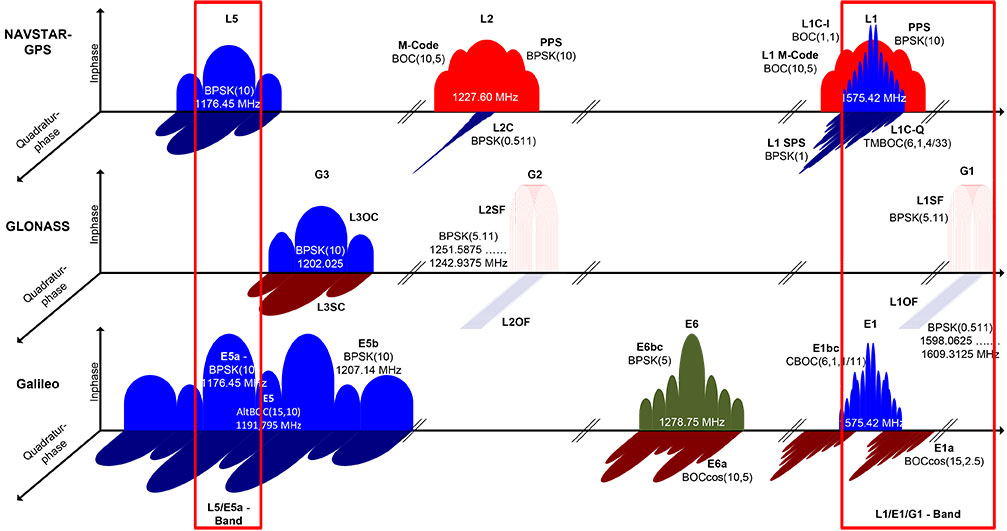
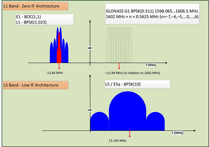
The NAPA chip features a monolithic, single mixed-signal chip implementation of a multi-system, multi-band analog front-end and the related digital baseband core, including an embedded processor. The NAPA chip can be used as a stand-alone GNSS sensor, because no additional components are required to obtain a PVT solution. The ASIC was implemented in a low-power technology and adopts some ad-hoc low-power architectural features. In regard to costs, an ASIC solution is more convenient than FPGA, provided the non-recurring engineering costs (NRE) are amortized by the amount of chips manufactured and sold. The NAPA chip supports multi-system (GPS, Galileo, and GLONASS) and multi-band (GPS/Galileo L1/E1, L5/E5a, GLONASS G1) processing. Figure 1 shows the frequency band being selected for receiving and processing in the NAPA chip. With two fully deployed GNSS — GPS and GLONASS — NAPA chips can already be used in many commercial applications. Thanks to the spectral overlay of the GPS L1/L5 and Galileo E1/E5a signals, the chip is also ready for Galileo. The frequency selection features both the narrow-band legacy signals L1/G1, which can be used for fast acquisition. For highest tracking accuracy, the wideband GPS L5 and Galileo E5a BPSK(10) modulated signals can be utilized.
Figure 1. GNSS signals received and processed by the NAPA chip.
The higher accuracy is obtained primarily by the attenuation of the ionospheric error. The ionosphere is a dispersing media that can introduce a bias error between 1 and 20 m. Forming a linear combination of two independent frequency-band measurements, the ionospheric bias can be measured and almost completely removed. In addition, Precise Point Positioning and Wide/Narrow-laning combinations are possible, thanks to the second received frequency band. The first allows for the combination of precise satellite positions and clocks with multi-frequency measurements, providing cm/dm solutions. The second adopts fast ambiguity solutions for carrier-phase positioning and cycle-slip detection.
In this article, we present the NAPA chip in detail. We describe the architecture of the analog front-end and its digital counterpart and the innovative features of each. Then we provide details about chip implementation, manufacturing, and test setup. Finally, we present the first verification results and draw conclusions.
Architecture Overview
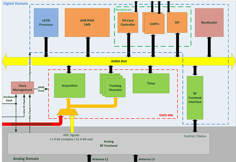
The NAPA chip architecture, depicted in Figure 2, is composed of two separate blocks integrated on the same silicon die: the analog core provides the functionality of a two-frequency radio-frequency (RF) front-end, whereas the digital part implements the main GNSS processing tasks, including the correlator channels and an embedded processor, and takes care of the RF front-end control. The interface between the two blocks is completely digital and provides synchronizers to ensure a valid clock domain crossing (CDC).
Figure 2. Overall NAPA architecture with emphasis on the digital core blocks.
Analog Front-End. The analog RF front-end supports the simultaneous reception of GPS L5 / Galileo E5a and GPS L1 / Galileo E1 / GLONASS G1 signals as well as modes where only one reception path is activated.
Both passive and active GNSS antennas are supported, thanks to integrated low noise amplifiers (LNA). There are two separate signal reception paths for the two frequency bands. The L1/E1/G1 path is characterized by a quasi-zero-IF conversion that mixes the middle frequency between L1/E1 and G1 to zero frequency. The L1/E1 reception bandwidth is up to 14 MHz so as to incorporate the MBOC modulations of Galileo E1 and future GPS L1C signals. A programmable automatic gain control (AGC) controls the complex analog baseband signals before they are digitized with a 4-bit dual-channel analog digital converter (ADC).
The second reception path receives an L5/E5a signal with up to 20 MHz bandwidth for the BPSK(10) modulated signals. This path uses a low-IF architecture. The signal is down-converted to an intermediate frequency (IF) of 15.345 MHz. The image frequency is suppressed by a polyphase filter. The real-valued analog signal is controlled by an AGC and converted to the digital domain using a single 4-bit ADC. A common phase locked loop (PLL) is used with specific L1/E1/G1 and L5/E5a dividers to generate the mixers’ local oscillator (LO) frequencies. The PLL loop filter is integrated on-chip to minimize external elements. Moreover, automatic filter and voltage-controlled oscillator (VCO) calibrations are included to mitigate process tolerances. The PLL can handle input clock frequencies between 10 and 80 MHz with a recommended clock frequency of 36.115 MHz.
An SPI core was implemented on the front-end part to facilitate control of the different front-end features. This means it is possible to tune the PLL, to switch off a complete front-end path if the second frequency band is not used and to activate different on-chip calibration procedures.
The frequency plan of the front-end is depicted in Figure 3. Due to the quasi zero-IF architecture, the complex L1/E1 baseband signal is located on an IF of -13.64 MHz and the GLONASS G1 frequency division multiple access (FDMA) signals on an IF of +12.94 MHz, with respect to the GLONASS G1 center frequency of 1602 MHz. The real-valued L5/E5a signals are provided by the second ADC and located on an IF of 15.345 MHz.
Figure 3. RF front-end frequency plan.
The ADC samples are generated with a frequency of 74.4871875 MHz for both the single channel L5, as well as for the dual-channel L1/E1/G1 ADCs. The ADC clock is also directly connected to the baseband digital core and is used as the main clock for the GNSS hardware modules. The embedded processor in the digital core receives a second clock, which is twice as fast as the GNSS hardware one.
Digital Baseband SoC. The baseband is characterized by a system-on-chip (SoC) architecture based on a SPARC-compatible 32-bit LEON2 microprocessor running at approximately 150 MHz. The GNSS functionality, including acquisition and tracking, are implemented using dedicated hardware modules.
The processor’s primary functions are to correctly configure the RF front-end and control the different parts of the receiver. In particular, it triggers acquisition, initializes, and starts the tracking channels with the signals detected during acquisition and takes care of closing the frequency/phase/delay locked loops (FLL/PLL/DLL) used for signal tracking. The tracking loops have strict real-time constraints; communication between the channels and the processor features a high-speed infrastructure.
Structurally, the processor is connected to a hierarchical on-chip Advanced Microcontroller Bus Architecture (AMBA) composed of a high-performance bus (AHB) and a peripheral bus (APB). The AHB provides a direct connection between the processor, the real-time GNSS modules, and the system memory, a monolithic 1 MByte block that hosts the main program at run-time. Different programs can be loaded if needed by using the external SD-card interface.
In addition to the processor, there are four additional AHB masters: the bootloader, the SD-card controller, the real-time GNSS modules, and the on-chip processor debugger. The bootloader is in charge of the bus control at system start-up. The SD-card controller has integrated direct-memory access (DMA) capabilities to move data between the SD card and the system memory. The real-time GNSS modules can write the tracking results directly to the system memory. Finally, the integrated processor debugger allows real-time debugging and is used mainly in the verification phase. The APB provides a connection to generic peripherals, and control and status interface of the GNSS modules without real-time constraints, as well as the control and status interface of the RF front-end. Since the GNSS modules operate in a separate clock domain that runs at half the frequency of the processor domain, some synchronization logic is necessary to ensure correct CDC.
The adoption of an SoC architecture provides higher flexibility than conventional static hardware solutions. In addition to typical GNSS applications, the user can also implement some signal monitoring and processing algorithms in software. The eCos-embedded operating system is provided to ease software development.
Generic Peripherals. The digital core is equipped with several peripherals that enable the communication with the outside world. The two separate universal asynchronous receiver/transmitter (UART) interfaces can run at 115.2 kbps. A dedicated serial peripheral interface (SPI) master is also provided with a maximum of 10-MHz clock frequency. For example, these interfaces can be used to provide NMEA data to some external display device or raw data (pseudoranges, code phases) in order to calculate a PVT solution. It is also possible to directly access the measurements generated from the correlator hardware and to control the tracking NCOs, which means users can choose their own algorithms for the loop closure. A possible application is the realization of vector-delay tracking using the NAPA ASIC and an external processor.
The SD-card interface facilitates the loading and storage of large amounts of data, for example, memory codes and almanacs. The possibility of making signal snapshots periodically and saving them to an SD card for later analysis has also been foreseen. This could be useful in special applications in which the receiver hardware is not accessible to the user all of the time.
In addition, 10 general-purpose I/O pins (GPIO) are provided. They can be controlled via software and can provide a very basic interface (for example, to connect to external LEDs or switches).
Acquisition Module. The acquisition module adopts a parallel code phase search in the Fourier domain by using a 16-k Samples Fast Fourier Transform (FFT) core. The adopted algorithm is known as parallel code-phase search.
The L1/E1/G1 signals coming from the front-end are first filtered and then sent to the acquisition module to allow a fast detection of the satellites in the L1/E1/G1 bands with their respective code delays and Doppler frequencies. The acquisition of GLONASS G1 FDMA signals is possible thanks to a software-configurable hardware mixer that can be set with the different G1 carrier frequencies. No direct hardware acquisition is supported for the L5/E5a band signals. The tracking of L5/E5a band signals is possible by performing a hand-over from L1/E1 band or a Tong search using the tracking channels.
The acquisition process is performed iteratively over all the possible satellites and over a set of Doppler values. These values are obtained by dividing the complete range of possible Doppler variations into bins. The smaller these bins are, the more accurate the acquisition result, but the more time is required to complete the entire process.
The acquisition has an additional layer of configurability because of the adoption of coherent and incoherent accumulations. These accumulations are supported in hardware but are completely software-controlled. This provides another possibility for achieving higher accuracy, but at the cost of a larger execution time due to an increase in the amount of accumulations.
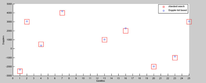
To speed up acquisition, we introduced a dedicated logic based on a novel patented algorithm. With this algorithm, we are able to detect the Doppler of the L1/E1 satellites present in the signal with an accuracy of 2 Hz. By performing this Doppler search step before the actual acquisition, we are able to generate a list with Doppler values that can be used instead of the bins. This gives more accurate results thanks to the algorithm’s inherent accuracy (see Figure 4) and allows a reduction in the acquisition time since the amount of Doppler values are usually smaller than the bins. Another advantage of this algorithm is the possibility to detect the transition to an indoor context (such as where there is a lack of satellite signals) by simply looking at the Doppler list, without performing any acquisition.
Figure 4. Comparison between standard and Doppler-list based acquisition of an L1 signal.
A single iteration step for the acquisition of a GPS L1 signal requires no more than 1 ms for each accumulated epoch. To achieve a good compromise between accuracy and speed, we typically use four epochs of incoherent accumulation, which means approximately 4 ms execution time. For Galileo L1 with four incoherent accumulations, an iteration step takes approximately 16 ms. This time has to be multiplied by the number of satellites and bins to estimate the execution time of the complete process.
Integrated Acquisition Memories. The acquisition module is characterized by dedicated memory blocks used for the fast FFT processing. It also provides the possibility to use these on-chip memories to store a snapshot of the incoming signals. In particular, we can store up to 81,920 samples of raw data for the complex L1 and real L5 IF signals for further analysis or processing, even off-chip. This enables sophisticated spoofing detection methods, for example, as well as interferer detection and characterization methods. Spoofing detection can be implemented by monitoring the 2D-acquisition search space. Interferer detection and characterization can employ short-time Fourier transforms (STFT) on the snapshot.
Using the chip as a simple snapshot receiver without having to use the on-chip dedicated GNSS hardware is also a possibilty. For this purpose, the integrated peripherals like UART and SPI ports are provided as interfaces.
Tracking Module. The 40 versatile tracking channels can be mapped to any combination of GPS, Galileo, and GLONASS signals on the two reception bands. One possible combination would be to track 10 GPS and 10 Galileo satellites simultaneously on both L1/E1 and L5/E5a bands. Alternatively, the user can include GLONASS signals by using fewer GPS / Galileo combinations. The assignment of these tracking channels to the actual GNSS signals can be changed at run-time in order to adapt to different reception situations or to assist the selected signal processing methods.
Each channel is characterized by a five-tap correlator. For the BPSK modulated signals without side peaks, such as GPS L1/L5, Galileo E5a, and GLONASS G1, we use only three values (early, late, and prompt). For Galileo E1 BOC(1,1) signals, five values are foreseen (very early and very late in addition to the previous), so that false peak lock conditions can be detected and a bump-jumping algorithm can be applied. The switch between these modes can be done at run-time and determines the amount of correlation values to be exchanged between correlators and processor.
Low-Power Features. The GNSS modules operate in their own clock domain. This clock domain is divided in clock-gated regions. There is a common region for the bus interfaces, one region for the acquisition, and one for each tracking channel. This allows a fine-grain shut-down of the GNSS modules that are not currently in use. For example, the acquisition can be deactivated when there are enough signals in tracking or the unused tracking channels can be disabled. This allows a reduced power consumption for the idle modules. This activation/deactivation procedure is controlled through a set of registers connected to the APB and is performed via software.
External Front-End Interface. To allow for more flexibility, we provided an additional RF front-end interface. The interface is also depicted in Figure 3. This interface features one 2-bit complex and an additional 2-bit real input, as well as a clock input. The user can decide to directly connect the digital baseband core to an external RF front-end with compatible sampling rate parameters, and exclude the on-chip RF front-end. This makes it possible to use the NAPA chip for validating other RF front-end devices, or it can be adapted to special customer needs.
Boot-Up Sequence. The SoC includes a hard-coded bootloader that is in charge of the bus control at start-up. In this phase, the processor is switched off. The bootloader loads a 24-kByte program from the SD-card to the system memory and starts the processor. In this phase, the processor runs with the external oscillator clock. Having performed the RF front-end initialization, the processor can switch to the front-end PLL generated processor clock that runs at approximately 150 MHz. This switch is completely transparent to the processor. Then the actual main GNSS receiver program is loaded into the system memory and executed.
The NAPA Chip
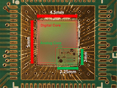
The NAPA chip has been manufactured in a low-power 1.2 V 65 nm TSMC technology. The 4.5 mm x 5.0 mm chip die was mounted in a QFN68 package; first test samples are available. The core requires a 1.2 V power supply, the pads 1.8 V. Figure 5 shows a picture of the die and its interconnections. The two parts, the analog core and the digital baseband, are clearly distinguishable. The chip is currently in the verification phase.
Figure 5. NAPA chip.
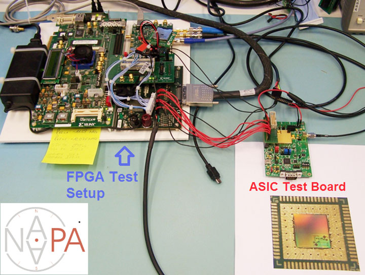
Within the project, the development and testing of the NAPA design was carried out on basically two platforms. During the hardware development phase, the baseband core has been prototyped on a FPGA device and tested using a special file-player setup, as explained in the following section. Having taped out the chip and received the first samples from the foundry, a test board has been developed in order to verify NAPA chip functionality.
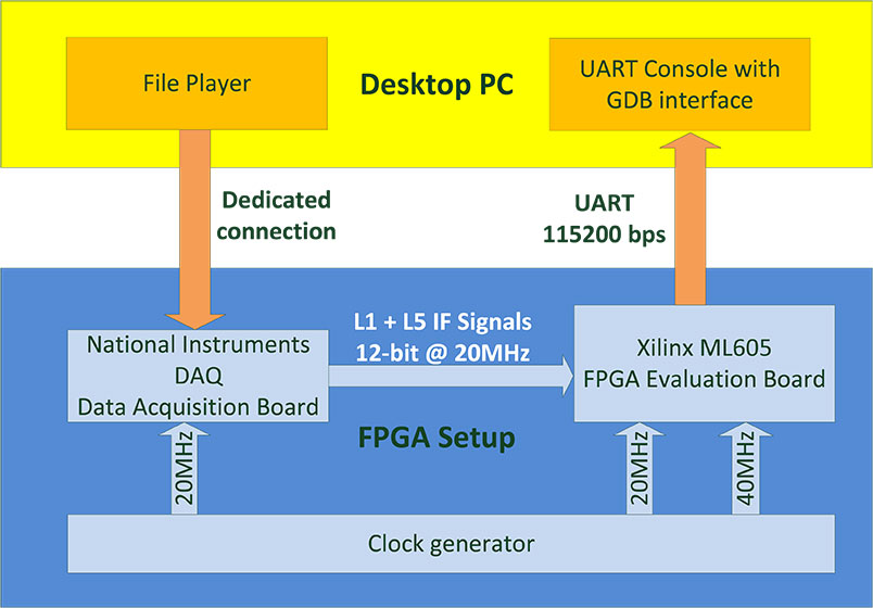
FPGA Test Setup. In the development phase, the NAPA baseband core has been implemented on a Xilinx Virtex6 FPGA device. A Xilinx ML605 development board has been used for the test setup. The main limitation of the testing in this phase was the lack of an analog RF front-end prototype. In order to make early testing of GNSS functionality possible, we adopted a file player developed by Fraunhofer IIS in a previous project. This file player uses a desktop PC to reproduce a digital signal data-stream stored in a binary file on the PC. The stream is sent through a dedicated interface to a commercial digital acquisition board. This board receives a clock synchronized with the baseband core’s clock in the FPGA and delivers the signals directly to the FPGA pins. The complete setup is depicted in Figure 6. The setup in use can be seen on the left part of the opening figure.
Figure 6. FPGA test setup.
Test Board. In the verification phase, which is currently ongoing, the first unpackaged test chip dies have been glued directly to the test PCB and bonded on board without any housing. After receiving the packaged chips, the QFN68 could be regularly soldered on the PCB. A block diagram of the board is depicted in Figure 7. The board hosts the typical switch buttons and LEDs for quick control and status detection as well as some specific interfaces. The clock can be provided through a dedicated SMA clock connector as well as a discrete oscillator. Two sub-miniature push-on (SMP) connectors are also provided for separate the L1 and L5 antenna inputs. The two UART ports, the debugger UART, and the SPI master port are connected using a FTDI chip. This chip allows the simultaneous connection of these ports to a desktop PC’s USB port. A parallel connector is provided to interface external front-end ADC signals and clock. The GPIOs are accessible through the same connector. A dedicated socket is added for a mini-SD card.
Figure 7. Block diagram of NAPA test board.
Preliminary Results
The chip on the test board was first tested using the same file player of the FPGA setup. This way, we could evaluate the correct functionality of the digital baseband core without the need to activate and configure the on-chip front-end. After the successful tests, we focused on the on-chip front-end configuration, and we used the antenna connectors to provide valid GNSS signals. We tested the chip using three different configurations: a GNSS signal simulator, a static roof antenna, and a small active patch antenna.
In the three configurations, we successfully acquired GPS L1 and Galileo E1 signals. We were also able to perform tracking on GPS L1 and L5I, as well as Galileo E1b and E5aI. Figure 8 shows the spectrum of a snapshot of L1 and L5 paths made using the on-chip dedicated snapshot hardware and sent through the UART port with a dedicated binary protocol for offline processing. For this special test, we used an arbitrary waveform generator to provide noiseless Galileo and GLONASS signals in the L1 and L5 frequency bands, supported by the NAPA chip. After performing a FFT of the two snapshots, we can clearly see these signals. In the L1 plot, the E1b signal is present in the negative frequency range with the two peaks typical of the BOC(1,1) modulation. The FDMA GLONASS G1 is in the positive frequency range with its trapezoidal characteristic. It is also possible to see a side lobe of the E1a BOCcos(15,2.5) in the proximity of the zero frequency. In the L5 plot, we can see the main peak of BPSK E5a signal on the right and its mirrored image on the left, due to the fact that L5 signal path is real.
Figure 8. Spectrum of L1 and L5 band showing a Galileo E1 and E5a signal.
Acknowledgment
This project has been funded by the Bundesministerium für Bildung und Forschung (BMBF) (German Federal Ministry of Education and Research), which is gratefully acknowledged.
In the June issue’s cover story, “Interchangeability Accomplished,” is a paragraph headed, “Satellite Intersystem Biases,” which appears to assert that Galileo System Time (GST) is 3 seconds ahead of UTC.
However, in the version of the Galileo Signal In Space Interface Control Document posted at: http://ec.europa.eu/enterprise/policies/satnav/galileo/files/galileo-os-sis-icd-issue1-revision1_en.pdf, paragraph 5.1.2 appears to indicate that Galileo System Time (GST) was synchronized, at the second level, with GPS time on 22 August 1999 (that is, 13 seconds ahead of UTC). And, given that a) GST, like GPS time, does not step for announced leap seconds, and b) the IERS has, as of today, announced 3 leap seconds since 22 August 1999, such would appear to suggest that GST is presently roughly 16 seconds (vice 3 seconds) ahead of UTC.
— Stuart Eventhal Fountain, Colorado
Author Frank van Diggelen replies:
Yes! You are right, the article should have said 16 seconds for Galileo, not 3. Thanks for catching that. I’ve corrected the text that appears in the online version of the article, and the accompanying figure.
Media Scoop
The online article covering Javad Ashjaee’s input on the GLONASS situation makes a positive statement that clarifies what has been a horrible reporting job across the board by news channels.
Fox, CBS, NBC, and ABC should all be ashamed that GPS World scooped them on what appears to be a simple story.
Good work.
— Mark Silver IGage Mapping Corporation Salt Lake City, Utah
To Consumer-Grade GNSS Chip Manufacturers
I would like you to consider including a very simple feature in your GPS functionality that will permit elevation to be identified to decimeter level in many instances. The changes needed to the chip are simply the ability to accept an accurate latitude and longitude input, and an elevation calculation function that uses input latitude and longitude.
In addition to enabling instantaneous calculation of an accurate elevation, it may be that a “residual better accuracy” will remain for some time after the calculation, and that this will permit substantially improved latitude and longitude identification at a close distance.
The geo-location scene has evolved rapidly over the past 20 years. It is now very commonplace to be able to locate the latitude and longitude of a location extremely quickly and extremely accurately. For instance, the Google Earth image from the front of my house shows the dotted dividing line in the center of the road. Measuring one of these lines in Google Earth gives a size of 3.1 meters by 20 to 30 cm wide. The lines actually measure 3.0 meters by 12 cm wide. From within Google Earth I can identify the latitude and longitude of the end point on the centre of this line to within ±10 cm with a high degree of confidence. In addition there may be some other small errors in Google’s reporting of the latitude & longitude (for example due to placement of the image or distortion of the image), but these are hopefully minimal.
Now if I place my GPS unit on the end center of this line in the road, I am provided with a result that I know is erroneous. The GPS horizontal location shown in Google Earth is very rarely within two meters of my known location. It is known that altitudinal accuracy is always some two times worse than horizontal accuracy.
If I can simply tell the GPS unit that I am at this known horizontal location, it is a relatively simple calculation to recalibrate the clock and pseudoranges to provide my elevation, which will have an accuracy of a two times the accuracy of the horizontal position. Decimeter horizontal accuracy will provide 2-decimeter altitude accuracy. This is close to 100 times better than the elevation accuracy currently available on any consumer grade stand-alone device and is also effectively instantaneous!
This functionality is simple to implement. I would hope that it could be implemented with nothing more than an upgraded ROM which includes a new API function to allow the input of “I know this is my current horizontal location” and an enhanced calculation process which uses this horizontal location to calculate altitude.
I am unsure whether a residual improvement in accuracy can be attained. Even an improved accuracy for 1 minute after the fix would be useful in many situations, and an improved accuracy for 5 to 10 minutes would be a boon.
Tri-Band Multi-Constellation GNSS in Smartphones and Tablets
This article presents a single-chip BeiDou/Galileo/GLONASS/
GPS/QZSS/SBAS architecture for use in cell phones and tablets. The authors explain the advantages to end users of multiple constellations. They also examine the details of system interchangeability, multi-system issues, and how assisted-GNSS data operates with all constellations, including BeiDou.
By Frank van Diggelen and Kathy Tan
With GPS, GLONASS, SBAS, BeiDou, QZSS, and Galileo there are over eighty operational satellites. Why do we need all these satellites in the first place? The answer is simple: in urban environments we want a few (six to eight) good satellites with an unobstructed line-of-sight (LoS) to the receiver and good horizontal dilution of precision (HDOP). In order to achieve this, we need many more satellites in space than any single constellation. In this article, we address the following issues.
Receiver intersystem RF bias with a tri-band front-end. BeiDou uses a different RF section than GPS/Galileo/QZSS/SBAS and GLONASS. As a result, there is a receiver intersystem bias between BeiDou and each of these other systems—not just because BeiDou is on a different frequency, but because of the different RF path through the receiver. We explain how this bias is calibrated and removed.
In the space segment there are intersystem biases primarily caused by differences in time standards. We discuss time management and show how the different systems can be made interoperable.
BeiDou Assistance. In order to realize the benefits mentioned, we need infrastructure deployment for BeiDou assistance in accordance with 3GPP standards. We will discuss what is available, and what is left to do.
Coverage outside of China. Europeans can see more BeiDou satellites than Galileos. At the time of writing (March 2014) they could see approximately twice as many. Thus, when used in a multi-GNSS receiver, BeiDou is far from being just a regional system. We will provide coverage analysis, and live-test data, including a focus on Europe.
Finally, we will demonstrate all of the above in practice, explaining and showing how interchangeability is achieved, and where first fixes can be computed with no more than one of each satellite type.
Figure 1 illustrates the point referenced at the beginning, that we need many more satellites in space than any single constellation.
All of the lines in Figure 1 show signals that were actively tracked by the receiver at the position shown on the right. The orange lines are to satellites that are blocked, but the reflected signal is tracked. We do not want to use these measurements if we can help it, so we need many satellites to provide enough LoS signals.
Let’s look at the HDOP of the LoS signals. In this example, the HDOP for the three LoS GPS satellites was 50. For the three LoS GLONASS satellites, the HDOP was 45. However, with the combined GNSS constellation, the HDOP for the six LoS satellites was 2.2. In other words, we expect about a 20x accuracy improvement by using the combined constellation.
There are many places and times in cities where we see just one or two direct LoS signals from a particular constellation, and we need more than just GPS and GLONASS to get the desired number of good signals, thus explaining the desire and need for all available constellations.
We’ll now look at the coverage provided by BeiDou2, which has five Geostationary satellites (GEOs), five inclined Geosynchronous satellites (GSOs), and four Medium Earth Orbit satellites (MEOs). With this 14-satellite constellation, the global coverage is as shown in Figure 2. This figure shows the percentage of time in a day that four or more BeiDou satellites are visible above a 10-degree mask angle. In the Asia-Pacific region, where the GEOs and GSOs are positioned, the coverage is predictably 100 percent. In fact, there are seven or eight BeiDou satellites visible in much of this region most of the time.
Figure 2. BeiDou2 global coverage.
As shown in Figure 3, outside the Asia-Pacific region the coverage is also interesting. We see that at least four BeiDou satellites are available over Europe about half of the time. This is quite significant given the previous discussion; even one or two extra satellites can make all the difference in an urban environment. Another notable fact is that, for now at least, Europe can see more BeiDou than Galileo satellites.
Figure 3. BeiDou coverage over Europe. The different colors show the percent of time that four or more BeiDou satellites are visible above a 10° mask angle.
Technical Requirements
There are five significant technical requirements that we want to satisfy when creating a multi-GNSS receiver for consumer applications:
Three Separate RF Paths. To acquire and track all of the satellites already mentioned, we need three separate RF paths. Details follow in Section 3 (Front-End Architecture).
Search and Track capability for all visible GNSS satellites. The receiver must have the ability to search a very large number of code-frequency bins at once.
Host-Based. As much as possible, we want to make use of the host application processor (AP) and memory. This allows for tight integration with assistance data (which is coming from the host), other sensors, and other wireless data (such as Wi-Fi and Bluetooth for indoor locations). A host-based architecture also keeps size and cost as low as possible.
With Host-Offload. A significant trend in location applications is the need for “always-on low power” location. The host AP cannot be used for continuous position updates, since it draws too much power. So, while we want host-based location when the host AP is active (such as when navigating with turn-by-turn directions and a map), we also want a host-offload capability so that the GNSS chip can compute positions internally while the host is asleep.
Interchangeability. The ultimate requirement for multi-system GNSS is the ability to use any combinations of satellites as if they were all in the same constellation. This is summarized as “any four satellites will do.”
Front-End Architecture
From a cell phone/tablet perspective, the signals in space are all in the L1 band, with frequencies as shown in Figure 4. The key architecture feature of the GNSS front-end is that it should have three separate RF chains for the three separate frequencies-of-interest; see Figure 5.
Figure 4. Frequencies-of-interest for GNSS in cell phones.Figure 5. Front-end architecture showing three RF chains.
Baseband Architecture
The preferred architecture of a chip, as shown in Figure 6, is host-based to take advantage of the large host CPU when it is active. When the host CPU is asleep, a small, low-power, on-chip CPU is leveraged for background “always on” location. This enables applications such as geofencing to run without significantly reducing battery life.
Figure 6. Block diagram of the preferred architecture, showing a host-based configuration that includes a host-offload capability for geofencing and position caching on-chip when the host is asleep.
When the host is active, such as when you are actively using the phone for turn-by-turn navigation, the host AP is on and we want to make as much use as possible of the host AP and memory. This allows for tight integration with assistance data coming from the host, other sensors, and other wireless data (such as Wi-Fi and Bluetooth for indoor locations). A host-based architecture also keeps size and cost as low as possible, even with host-offload capability, which adds very little to the size of the chip.
Receiver Intersystem RF Biases
With the three different bands of frequencies, we will get RF group delays in the receiver front-end. These must be calibrated out by the receiver’s designer as part of the chip’s system design. If the group delay between BeiDou and GPS is not calibrated, it will lead to approximately three meters of bias between the two systems (Figure 7). Once it is calibrated, there is essentially no bias.
Figure 7. L1 frequency spectrum for BeiDou2, GPS, Galileo, QZSS, SBAS, and GLONASS.
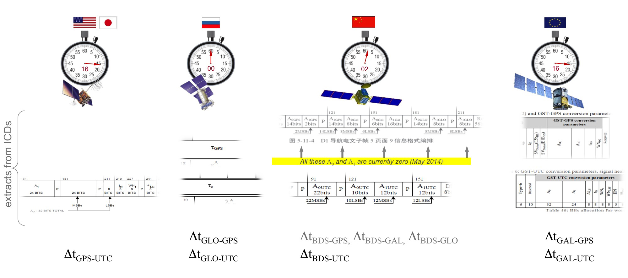
Satellite Intersystem Biases
Different GNSS constellations run off their own master clocks; referenced to different realizations of UTC. GPS is referenced to UTC (USNO), QZSS is referenced to UTC (NICT), GLONASS to UTC (SU), BeiDou to UTC (NTSC), and Galileo to UTC (INRIM). GLONASS UTC (SU) differs from the others by 3 hours.
Furthermore, different systems treat leap seconds differently. This is indicated by the red arrows in the clocks in FIGURE 8. GPS, QZSS, BeiDou and Galileo system times are continuous and ignore leap seconds. Thus, each system time is ahead of UTC by a number of leap seconds. GPS time started in 1980 in synch with UTC; there have been 16 leap seconds since, so now GPS is 16 seconds ahead of UTC. QZSS and Galileo system times were started in synch with GPS. BeiDou system time was started in 2006 in synch with UTC; there have been 2 leap seconds since, so now BeiDou is 2 seconds ahead of UTC. GLONASS system time, on the other hand, includes leap seconds.
Apart from this, each of the different realizations of UTC is within several nanoseconds of the others.
To combine measurements from these different systems and avoid any time-induced intersystem biases, we need to resolve the time offsets. Each system transmits the delta-time between its system time and the systems that preceded it, as listed in Figure 8. To combine the systems, we either need to decode these data messages or obtain the delta-time values from Assisted GNSS.
Figure 8. Intersystem time differences and broadcast delta-time values from each system.
Note, however, that in the BeiDou broadcast Nav message the intersystem time-offset data values are all set to zero (even though the true offsets are not zero).
Assisted-GNSS Including BeiDou
Assisted GNSS, or A-GNSS, increases sensitivity and decreases the time-to-first-fix of a receiver by providing assistance data in the form of the receiver’s approximate position, time and frequency, as well as all data that the receiver might decode from the broadcast signals. The assistance data may also include data beyond what is broadcast, in particular, let’s focus on BeiDou time offsets. The BeiDou time offset to the other systems is included in the BeiDou broadcast Nav message as shown in Figure 8; however, at present these data values are all set to zero (even though the true offsets are not zero). Thus, in order to get these offsets and integrate BeiDou properly into a combined GNSS system, one must compute the offsets at a reference station and provide them as part of the assistance data, as shown in Figure 9.
Figure 9. A-GNSS provides broadcast satellite data over some other wireless network, as well as time-offsets between the different pairs of systems.
Commercial Implementation
The preferred architecture described in this article has been implemented in a commercial GNSS receiver that is now available for commercial host-based products, such as cell phones and tablets. The chip, Broadcom’s BCM47531, is the first consumer GNSS chip with a tri-band front-end capable of acquiring and tracking satellites from GPS, SBAS, QZSS, GLONASS, and BeiDou constellations, simultaneously; and operating in host-based mode for navigation and in host-offload mode for Always-On location.
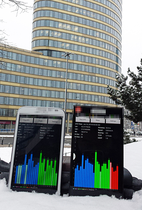
Broadcom has collaborated with leading smartphone manufacturers to launch the first wave of BeiDou enhanced consumer smartphones. Figure 10 shows one of these smartphones being tested in Europe. Note the number of BeiDou satellites in view. As predicted by the availability plots shown earlier, there are many BeiDou satellites in view (in this case, six).
Figure 10. GPS/GLONASS phone and GPS/GLONASS/BeiDou phone being tested in Warsaw, Poland. Note the six BeiDou satellites (red) that are seen and tracked by the BeiDou phone.
Interchangeability: Any Four
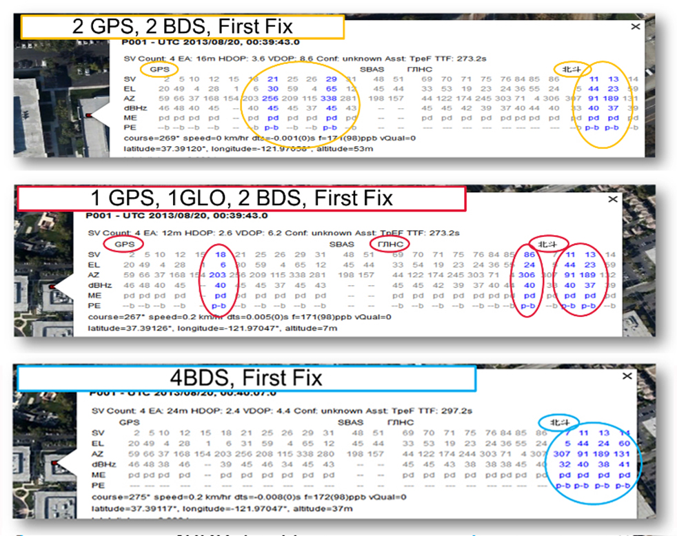
Now that we have addressed all of the major issues related to integrating different GNSS systems (in particular BeiDou), we can demonstrate the payoff.This is the achievement of interchangeability, where any GNSS satellites can be used together, as if they all belong to a single constellation. Figures 11 and 12 show assisted cold starts, where first fixes are obtained with no prior knowledge other than that provided by A-GNSS data. In each case, we show a different combination of satellites; including one satellite from each of four different constellations, and all four from BeiDou.
Figure 11. Interchangeability: Position fix with 1 GPS satellite, 1 GLONASS, 1 QZSS, and 1 BeiDou. The receiver is in Perth, Australia, where all of these constellations can be seen.Figure 12. Interchangeability: Assisted cold start, first fixes. Blue numbers show the satellites used in the position fix (top: two GPS and two BeiDou; middle: one GPS, one GLONASS, and two BeiDou; and bottom: four BeiDou only). The receiver is in San Jose, California, where four BeiDou satellites can be seen some of the time (some of the BeiDou GSOs can be seen and all the BeiDou MEOs can be seen for a few hours each day).
Multi-Constellation Robustness
While this article was being edited, the GLONASS system provided us with the most dramatic demonstration yet of the need for, and benefits of, multi-constellation receivers. On April 2, 2014, the GLONASS system failed spectacularly for a period of 11 hours. Receivers that used GPS and GLONASS had very large position errors, or no positions at all. While the receiver discussed in this article, the BCM47531, operated seamlessly. This receiver tracked GPS, GLONASS, QZSS and BeiDou satellites, correctly identified the faulty GLONASS satellites, and automatically stopped using them.
The details of the incident are as follows: The GLONASS control system uploaded incorrect orbit data to several satellites. When receivers used these satellites they had position errors of hundreds of meters, or no positions at all. At that time, the BCM47531 was being tested alongside a GPS/GLONASS receiver, and we have the data to show what happened. The receiver using only GPS/GLONASS suffered position errors of ten thousand meters, and long periods with no position at all; at the same time the multi-constellation receiver produced continual positions with normal accuracy. Figure 13 shows the test data — the left most image shows the route being driven, the middle image shows the data from the GPS/GLONASS receiver, and the right image shows the data from the BCM47531 multi-GNSS receiver. Figure 14 shows the details of the multi-GNSS receiver, you can see that no GLONASS satellites are being used.
FIGURE 13. Side-by-side tests of GPS/GLONASS receiver and multi-constellation receiver during the GLONASS incident of April 2, 2014. The GPS/GLONASS receiver produced errors of ten thousand meters and long periods with no position at all, while the multi-constellation BCM47531 operated seamlessly.FIGURE 14. Detail from the multi-constellation receiver when there is a problem with some satellites. The errors are recognized automatically by algorithms comparing the measurements to redundant measurements from the extra constellations, and the erroneous signals are not used.
This incident may raise the question: Why use GLONASS at all, why not just GPS? The answer is that in urban canyons, such as where this test was done, GPS alone does not have enough satellites to give the performance now expected in consumer products — for the reasons explained in the beginning of this article. Also, GPS, although it has been more reliable than GLONASS, is not immune to failures or jamming itself. The lesson of this incident is that reliability and accuracy comes from the combination of all the available constellations, with a receiver that can use the signals interchangeably.
Conclusion
We have shown the preferred architecture for a consumer GNSS receiver that includes all of the available constellations. We have addressed the major requirements of such a receiver for the consumer market, in particular, for cell phones and tablets. A receiver that meets these requirements is now available, the Broadcom BCM47531, has been designed into a new generation cell phones and tablets for 2014. Finally, we have shown how, with this receiver, the ultimate GNSS goal of interchangeability can be achieved.
Frank van Diggelen is vice president of technology at Broadcom Corporation, a consulting professor at Stanford University, and inventor of coarse-time GNSS navigation, co-inventor of Long Term Orbits for A-GNSS, and author of A-GPS: Assisted GPS, GNSS, and SBAS.
Kathy Tan is a senior principal engineer at Broadcom Corporation. She has worked on GNSS development and Assisted GNSS for Ashtech, Magellan, Global Locate and Broadcom. She received her MS and BS in electrical engineering from Fudan University, China.
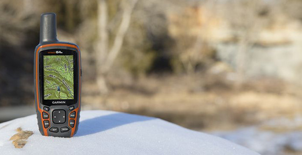
Garmin International Inc., a unit of Garmin Ltd., today announced the GPSMAP 64 series of rugged outdoor handhelds. The GPSMAP 64 series brings a dual GPS and GLONASS receiver, preloaded geocaches and smartphone connectivity for LiveTrack and Smart Notification to its product line for hikers, hunters, and geocachers.
“Building on the popularity of the GPSMAP series, the new GPSMAP 64 series improves functionality to make a top-notch device even better,” said Dan Bartel, Garmin vice president of worldwide sales. “The GPSMAP 64 is ideal for anyone, no matter if it’s their first handheld, or if they’ve used Garmin for years. It combines trusted Garmin technology with the comfort of a device people know and love.”
The GPSMAP 64 series has a 2.6-inch sunlight-readable transflective color display and a high-sensitivity GPS and GLONASS receiver with a quad helix antenna for superior reception. With the addition of GLONASS satellites, the time it takes for the receiver to lock on to a position is (on average) approximately 20 percent faster than using GPS alone. This allows users to get their position quickly and precisely even in heavy cover and deep canyon.
The GPSMAP 64 series features three distinct water-resistant (IPX7) models to suit various activities and interests. The basic GPSMAP 64 includes a built-in worldwide basemap with shaded relief, and supports BirdsEye Satellite imagery and TOPO U.S. 24K maps. The GPSMAP 64s adds a 3-axis electronic compass and barometric altimeter. Additionally, the 64s adds wireless connectivity for data transfer between other compatible Garmin handhelds and mobile apps, and for Smart Notification technology. With this, users can receive emails, texts and alerts on the device (when paired with an iPhone 4S and later). This allows users’ smartphones to be safely protected from the elements. The 64s also comes with a one-year subscription of BirdsEye Satellite Imagery. The GPSMAP 64st includes preloaded U.S. 100K topographic maps. With this, users will be able to search for points of interest by name or proximity to their location and view descriptive details for terrain contours, topo elevations, summits and geographical points.
For outdoor adventurers, the rugged GPSMAP 64 devices are compatible with BaseCamp, a free software download that allows users to view and organize maps, waypoints, routes and tracks. The 64s and 64st models are compatible with the BaseCamp mobile app for data transfer, and the Garmin Connect mobile app, for features such as LiveTrack. With LiveTrack, users can pair their device with the app, and invite friends and family to follow their activity in real time. This provides peace of mind, especially if users are alone. Through ANT+, the 64s and 64st models are also compatible with external sensors such as an external temperature sensor and heart rate monitor. With ANT+, the 64s and 64st models can act as a remote for the new VIRB and VIRB Elite action cameras.
Each device comes preloaded with the locations of 250,000 geocaches from Geocaching.com. Devices store and display key information to find the hidden containers including the geocache coordinates, terrain rating, its difficulty, hints and descriptions, so users no longer have to manually enter coordinates or print out geocache info. By going paperless, users are helping the environment, and improving their efficiency. If users would like to continue geocaching beyond the preloaded geocaches, when they register their device they can sign up for the free premium membership trial through Geocaching.com, and download more geocaches. The GPSMAP 64 devices can store millions more, so users will no longer have to pick and choose which geocaches they want to load on their device.
All of the devices in the GPSMAP 64 series have a dual-battery system, where both standard AA batteries and a rechargeable NiMH battery pack (sold separately) can be used. The devices have internal memory (4GB for 64/64s and 8GB for 64st), and a microSD card slot to store additional data and maps.
The new GPSMAP 64 series will be available this month. The GPSMAP 64 will retail for $299.99, the GPSMAP 64s will retail for $399.99, and the GPSMAP 64st will retail for $499.99.
Phones sold in Russia will have to use GLONASS or GLONASS + GPS as of 2014, according to a report from the Voice of Russia. Phones with only GPS will be illegal in Russia, and any mobile devices imported will have to support GLONASS.
A new bill claims that in order to guarantee stable operation of a unified telecom network in Russia regardless of conditions, it’s necessary that the satnav system used be the one controlled by the Russian Federation. New requirements for mobile devices with satellite navigation capabilities are expected to follow.
The authors of the bill note that after the bill is adopted, its requirements will cover all manufacturers and vendors of cellphones, making it impossible to sell a mobile device without GLONASS support.
The Telecom Ministry and industry watchdog Roskomnadzor will oversee the changes.
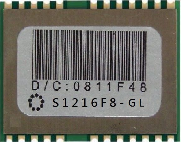
SkyTraq Technology, Inc., a fabless GNSS positioning technology company, has introduced its fast consumer-grade 50-Hz update rate S1216F8 GPS receiver module. The module supports GPS, QZSS, WAAS, EGNOS, MSAS, and GAGAN satellite signal reception. The S1216F8 receiver is based on SkyTraq’s newest 55-nm Venus 8 GPS/GNSS chipset.
The Venus 8 is a low-cost commercial GPS/GNSS chipset incorporating an IEEE-754 compliant FPU. With RISC/FPU running at 100 MHz, the S1216F8 GPS receiver module has industry leading 50-Hz update rate, very fast and accurate position/speed response, suitable for UAV, RC plane flight logging, and high-performance race car or speed boat data logging applications. When running at lower 1 Hz, 5 Hz, or 10 Hz update rate, the S1216F8 receiver can be used as a typical GPS receiver module currently available on the market.
The S1216F8 GPS receiver module measures 12mm x 16mm and consumes 26mA @ 3.3V during continuous navigation at 50-Hz update rate.
The S1216F8 is among SkyTraq’s S1216 family of form factor compatible, high-performance, low-cost GNSS modules. The S1216F8-GL GLONASS/GPS module and S1216F8-BD Beidou/GPS module both have a 20-Hz update rate.
The S1216 family of 50-Hz GPS, 20-Hz GLONASS/GPS, and 20-Hz Beidou/GPS receiver modules are in production. Datasheet, engineering sample, evaluation kit and reference design are available.
DJI, developer and manufacturer of UAV systems, today announced the launch of the Phantom, the company’s first easy-to-fly, consumer quadcopter. Accorrding to DJI, before the Phantom, building and flying multi-rotor aircraft was a complex task only performed by professionals and extreme hobbyists. With the Phantom, DJI brings professional-level multi-rotor flight control technology to the average person by incorporating DJI’s intelligent, GPS-based autopilot system into the Phantom. This provides for simple, ultra-stable and reliable flight characteristics right out of the box. Priced at $679, the Phantom is also half the price of competing units that require complex building and soldering to assemble.
The Phantom comes with a remote-control unit containing pre-programmed autopilot parameters and a GoPro camera mount, making aerial cinematography easy for almost anyone, the company said. With the built-in DJI Naza-M autopilot system with GPS module, the Phantom has both GPS Attitude and Attitude Control Mode. Pilots can switch between the two modes to achieve particular flight experiences. Also incorporated are safety parameters, such as a failsafe feature that will bring the Phantom back to its take-off point and land itself if it loses signal from the remote control unit for any reason.
Features of the Phantom:
Highly integrated design with high intensity orientation-aiding LED indicators
Ready-to-fly right out of the box – no programming needed
Stable and easy to fly with agile performance
Multiple flight modes, including GPS position hold
Intelligent Orientation Control (IOC)
Failsafe and auto go-home/landing
Camera mount included for GoPro.
“DJI has always been at the forefront of both UAV flight control systems and innovative airframe technology,” stated Colin Guinn, CEO of DJI North America. “The PHANTOM is more than an evolution of our existing technology, it is a quantum leap forward in bringing professional-level, multi-rotor aircrafts to the average consumer.”