Quectel Wireless Solutions has launched the SG865W-WF, a new generation of flagship Android smart module. The module is equipped with Qualcomm’s QCS8250 system-on-chip (SoC), which offers powerful performance and rich multimedia functions to meet industrial and consumer artificial intelligence IoT (AIoT) scenarios.
Quectel made the announcement at the Consumer Electronics Show (CES) taking place this week in Las Vegas.
With various peripheral interfaces such as dual USB, multiple PCIe and UART, the product can seamlessly integrate with cellular and GNSS modules such as Quectel’s EC20 LTE module, and the RG500Q 5G module, allowing customer terminals to be connected flexibly to 4G/5G networks and achieve faster and more accurate positioning.
The SG865W-WF module will accelerate the efficient deployment of high-end AIoT applications such as video conferencing, cloud gaming, digital signage, unmanned aerial vehicles (UAVs), robots and smart retail.
With 106 operational GNSS satellites flying today (or was that yesterday’s number?) satnav’s backbone is robust, variegated, supportive of growth across many industries — and poised to leverage even more prosperity. I’ve seen forecasts of as many as 400 satellites, well beyond GNSS proper and involving low-Earth orbit telcomm constellations, constantly patrolling space above us and beaming down positioning, navigation and timing (PNT) intelligence.
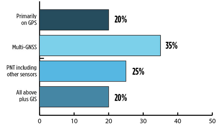
Where do you see your efforts focusing primarilly over the next decade? (Source: GPS World’s 2018 State of the Industry survey)
A draft headline for the cover of this issue — The Sky’s the Limit! — actually underestimated. Not even the sky is the limit.
Mobile. GNSS-enabled tablets and smartphones provide navigation, traffic and congestion maps to billions. These features will continue to drive demand for GNSS in all electronic equipment. As we move from the internet to the internet of things (IoT) as the dominant paradigm of advanced and developing societies, GNSS will boom louder than we have heretofore known it to do.
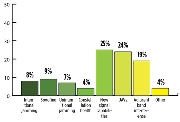
What is the industry “Issue of the Year?” (Source: GPS World’s 2018 State of the Industry survey)
Communication and location-enabled transportation services such as Lyft and Uber provide only one example of novel GNSS uses that have become the norm.
Tracking devices, whether personal, vehicular, or affixed to large assets, constitute a quiet though muscular growth market. The GPS tracking device generates high demand from industries such as information technology (IT), transportation, and telecommunication, providing real-time intelligence and advance diagnoses about products, vehicles and people, valued by consumers and businesses, enhancing security and safety — key concerns that will only grow in an increasingly vulnerable world.
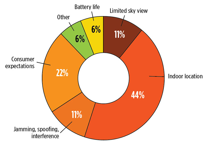
What is the key challenge for positioning and navigation in the wireless and consumer space? (Source: GPS World’s 2018 State of the Industry survey)
Volume! The GPS tracking segment alone is expected to reach $2.53 billion by 2023, nearly 12% annual growth. Other mobile segments will increase in parallel. Don’t be deceived by the low-cost of low-accuracy tracking devices. Volume! Volume! Volume! is just as powerful a mantra as Location! Location! Location!
With the wireless carriers and IoT behind it, GNSS will see growth a-plenty and virtually no downside. U.S. cell carriers are now selling access to your real-time phone location data, a key signal that economic giants put high value on the technology.
For more results from the 2018 State of the GNSS Industry, see this page.
By Changfeng Yang, Chief Architect of BeiDou Navigation Satellite System
Changfeng Yang
As one of the four major GNSS providers, the establishment of BeiDou Navigation Satellite System (BDS) has been steadily developed, following a three-step strategy. By around 2020, BDS will form a nominal space constellation consisting of 30 satellites, including three satellites in geostationary Earth orbit (GEO), three satellites in inclined geosynchronous satellite orbit (IGSO) and 24 satellites in medium Earth orbit (MEO). It will provide global users with open and high-quality services free of charge, including navigation, positioning, timing, short message communication, search and rescue and so on.
BDS is aimed at developing into a world-class global navigation satellite system, with innovative and advanced technologies, extraordinary user experience, international development and worldwide presence, which can provide fundamental time and space reference for national defense and economic-social development, and advance the progress of high-tech and IT industries.
BDS has initiated several innovative attempts in the fields of both international satellite navigation and domestic aerospace for the first time, and paved a unique development path of a satellite navigation system, with an eye on the state conditions and distinctive features. On Jan. 9, 2017, the BD-2 Project won the top National Scientific and Technological Progress Award. In 2017, BDS achieved fruitful results in the aspects of system construction, integrated applications and international development.
System Construction
Through upgrading and reconstructing the ground system, the service performance, stability and availability of the BD-2 constellation have been improved. To achieve user-oriented services, the updated Interface Control Document (ICD) for B1C and B2a open service signals (Version 2.1) was released in accordance with the constellation change.
The international GNSS Monitoring and Assessment System (iGMAS) has been built, consisting of eight domestic monitoring stations and 16 overseas stations, to monitor and assess the service performances of BDS, GPS, GLONASS and Galileo at real-time worldwide. It has taken all factors into consideration, including constellation status, signal-in-space, navigation message, service performance and high-precision products, and so on. According to its analysis results, the nominal positioning accuracy of the BD-2 system in the coverage area has been optimized from 10 meters to 8 meters.
Development of the BD-3 System. On Nov. 5, the first pair of the 24 BD-3 MEO satellites were successfully launched, while another pair is planned to be launched by the end of the year.
Liftoff of the first pair of the BD-3 MEO satellites on Nov. 5, 2017. (Credit: Xinhua)
The BD-3 satellites are equipped with B1C and B2a signals with optimized performance, which are compatible and interoperable with other GNSS signals. The interface control document of B1C and B2a signals (beta version) was released in September. The BD-3 satellites also adopt the higher-performance rubidium atomic clock with stability of E-14 and hydrogen atomic clock with stability of E-15. By utilizing new technologies, the signal-in-space (SIS) accuracy will be superior to 0.5 m; the position accuracy will be doubled or quadrupled, and reach 2.5 m to 5 m.
The BD-3 system will retain the short message communication service of its predecessors, and further enhance basic positioning, navigation and timing (PNT) service capabilities. Satellite-based augmentation system (SBAS) and search-and-rescue (SAR) services will be added and developed according to international standards.
After in-orbit tests and networking validation, the BD-3 satellites will be able to provide operational services, and accelerate the global coverage of BDS.
Ground-Based Augmentation. The Phase I construction of the BDS/GNSS ground-based augmentation system has been completed, consisting of 150 framework reference stations, 1,200 reference stations of higher density network, national data processing center, six industrial data-processing centers, and manufacturing of user terminals. This system has achieved basic service capabilities, and its service performance standard (version 1.0) has been released. Through integration with the internet, a cloud platform has been established to provide high-precision space-time information services, including real-time navigation services at meter-level and decimeter-level, as well as precise positioning services at centimeter-level and millimeter-level.
Satellite-Based Augmentation. Based on the International Civil Aviation Organization (ICAO) standards, system demonstration and validation work on the BeiDou Satellite-Based Augmentation System (BDSBAS) has been completed, and the technical status of the system has been confirmed in accordance of the next-generation SBAS Dual Frequency Multiple Constellation (DFMC) standards.
Integrated Applications
Currently, a great number of independent, self-controlled intellectual property rights on the fundamental BDS products have been achieved. World-class, advanced technologies have been developed. With the release of the first Chinese in-house developed meter-level fast positioning BDS chip, BDS applications have begun to embrace the era of meter-level positioning.
In 2017, the sales volume of BDS navigation chips and modules exceeded 50 million pieces, and that of high-precision surveying boards and navigation antenna captured 30% and 90% of market shares respectively. There are more than 14,000 enterprises (including more than 50 publicly listed companies), and more than 450,000 employees in China engaging in BDS-related business.
The annual output value of the publicly listed company in 2017 is more than RMB 50 billion (US $7.53 billion). The number of terminals produced by domestic enterprises surpasses 40 million pieces/sets. BDS has gained recognition from mainstream chip producers such as Qualcomm, Trimble, Hemisphere GNSS, Huawei, Samsung, u-blox, MTK, Broadcom, NovAtel and more, and the total number of terminals is estimated to surpass 300 million pieces or sets.
BDS continues to:
promote integrated applications and development of related industries;
bring GNSS high-precision services in combination with cloud computing, Internet of Things, big data and other technologies;
push forward the integration between BDS-related industries and high-end manufacturing, software, and integrated data industries.
BDS has been applied in the transportation, logistics, emergency rescue, marine fishing and other fields, which has greatly improved production efficiency, reduced resource consumption, and lowered pollution. For example, benefiting from the BDS applications in traffic management industry, the number of major accidents has decreased by 46.7%, and the death toll has been reduced by 48.9%. With BDS-based maritime applications, more than 10,000 lives have been saved.
BDS/GNSS augmentation services have been applied to precision agriculture, land mapping, monitoring on deformation and displacement of large-scale public facilities, and earthquake and geological hazard measurement and survey; the latter has provided important monitoring for public safety. As a result, the production of precision agriculture has increased by 5%, and the oil consumption by agricultural machinery has decreased by 10%. The time for surveying and mapping of national land is shortened from a few days to several seconds.
BDS has been fully put into mass applications. BDS-based navigation services have been adopted by various enterprises, such as Huawei, ZTE, Baidu, Autonavi, Alibaba, JD and others in the fields of manufacturing of mobile and smart terminals, location-based services (LBS), e-commerce, and so on. BDS-based LBS have been widely applied in the mass consumption sector and people’s livelihood, and many innovative applications have emerged, such as caring for seniors and children, shared vehicles, BDS-based logistics, and so on, which have been changing people’s lives and providing more convenience for the public.
International Development
At present, BDS has covered more than 50 countries and more than 3 billion people. BDS-related products have gained access to the markets of more than 70 countries and regions, more than 30 of which are along the (land-based) Belt and (maritime) Road (in line with the Belt and Road Initiative). Through joint applications with other compatible navigation satellite systems, BDS provides global users with diversified choices for better application experience.
Meanwhile, the iGMAS has contributed to the implementation of the Asia-Pacific Space Cooperation Organization project, iGMAS-International GNSS Service Pilot experimental project, and Sino-Russian monitoring and assessment cooperation, and has provided GNSS users with authentic third-party assessment results. China continuously pushes forward BDS to be recognized by the ICAO, International Maritime Organization (IMO), mobile communication standard Partnership Project and other organizations, to serve the world in line with international conventions.
In October, three PRN codes which are essential to the development of BDSBAS were assigned; the SBAS service provider identifier and UTC standard identifier have been assigned to BDSBAS by ICAO, which marks BDSBAS an official SBAS provider in the ICAO family, and lays the foundation for the follow-up construction of BDSBAS, as well as its provision of standard navigation services for the civil aviation sector.
In March, a multi-system (including GPS, BDS and GLONASS) ship-borne receiver standard was approved by the IMO. BDS has also been included in the PNT guidelines of maritime applications.
In the field of mobile communication, 26 technical standards that support the BDS positioning function have been adopted by the third- and fourth-generation mobile communication standard Partnership Projects.
Future Plans
BDS will keep improving its continuous stability and service accuracy. Two more BD-2 replacement satellites will be launched in 2018, ensuring its regional service performance will be remain stable and be enhanced.
Eighteen BD-3 MEO satellites and one BD-3 GEO satellite will be launched by around the end of 2018. Upon the deployment of those 19 satellites, BD-3 will possess the initial operational capability and serve the countries along the Belt and Road. The official version of ICD for B1C and B2a open service signals, as well as other system documents, will be released, in line with the operational status of BD-3 satellites, for the convenience of public applications.
In regard to augmentation systems, China plans to complete the construction of Phase II BDS/GNSS ground-based augmentation system in 2018, and advance the recognition of BDS-based high-precision services as public goods. In 2018, the first BDSBAS GEO satellite with the BDSBAS payload will be launched to start the deployment of the BDSBAS system.
In terms of applications and international development, China will give full play to the role of BDS in the integration procedure between industrialization and IT applications, to promote the development of information industry, adjustment and upgrading of industrial structure.
China will also strengthen the cooperation and communication with other navigation satellite system providers, carry out coordination under the framework of international organizations and multilateral platforms, improve the international development of BDS, provide better services for users along the Belt and Road, and expand BDS services to serve users worldwide.
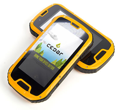
The CT4 and other rugged handhelds by Cedar Tree Technologies will now be available through Juniper Systems.
Juniper Systems is merging its subsidiary company, Cedar Tree Technologies, into Juniper Systems. The move will allow customers to purchase Cedar’s Android-operated rugged handhelds directly from Juniper Systems.
Juniper Systems launched Cedar Tree Technologies as a rugged handheld company in August 2014.
“With a reputation for top-of-the-line, ultra-rugged handheld computers, Juniper Systems aimed to expand its products to meet the needs of customers who may not need the outstanding level of ruggedness or support that Juniper handhelds provide. And that’s how Cedar Tree Technologies began. Cedar handhelds lie somewhere between consumer devices and Juniper Systems’ ultra-rugged handhelds, providing a mesh of both ruggedness and affordability,” said a statement from the company.
Cedar handhelds run on the Android operating system, offering access to thousands of business-ready apps and Google services via the Google Play Store. This provides users with an off-the-shelf product, eliminating the need to download third-party data collection software. Juniper Systems has published a blog post that outlines the differences between Cedar and Juniper handhelds.
The Cedar product line that Juniper Systems will now be carrying includes three new handheld devices:
CT7 Rugged Tablet. Featuring a large, 7-inch display, the CT7 tablet is IP67 waterproof and dustproof, and is priced at $899 USD.
CT4 Rugged Handheld. The CT4 handheld is a more compact device than the CT7. Featuring a 4.3-inch display and an IP68 waterproof and dustproof rating, it is priced at $489.
CMP1 Miniphone. The CMP1 Miniphone is rated IP65 (dustproof and resistant to water), and is ideal for swapping out a regular smartphone for outdoor excursions, for kids, or for use as an emergency phone. The CMP1 sells for $124.
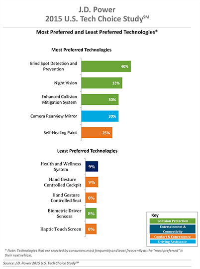
Three of the top five technologies consumers most prefer in their next vehicle are related to collision protection, according to a new J.D. Power 2015 U.S. Tech Choice Study.
Technologies that reduce the overall burden of driving and enhance the safety of the vehicle and its occupants receive the most consumer attention. Among the technologies consumers express most interest in having in their next vehicle are blind spot detection and prevention systems, night vision, and enhanced collision mitigation systems. These findings demonstrate growing customer acceptance towards the concept of the vehicle taking over critical functions such as braking and steering, which are the foundational building blocks leading to the possibility of fully-autonomous driving. The only non-collision protection technologies to crack the top five are camera rearview mirror, which falls into the driving assistance category, and self-healing paint, a comfort and convenience category.
In contrast, technologies in the navigation category have low preference across all vehicle price segments.
The inaugural study uses advanced statistical methodologies to measure preference for and perceived value of future and emerging technologies. A total of 59 advanced vehicle features are examined across six major categories: entertainment and connectivity; comfort and convenience; collision protection; driving assistance; navigation; and energy efficiency.
“There is a tremendous interest in collision protection technologies across all generations, which creates opportunities across the market,” said Kristin Kolodge, executive director of driver interaction and HMI research at J.D. Power. “In contrast, there is very little interest in energy efficiency technologies such as active shutter grille vents and solar glass roofs. Owners aren’t as enthusiastic about having these technologies in their next vehicle because of other efforts automakers are taking to improve fuel economy, as well as relatively low fuel prices at the present time.”
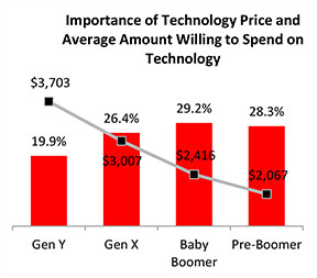
Gen Y Willing to Spend Most for Technology
Across all generations, price is the most important consideration for technology, accounting for 25.2 percent of importance. Gen Y is the least sensitive to technology price and shows a greater willingness to spend on new technologies than the other generations. Gen Y consumers, who have accounted for 27.7 percent of new-vehicle sales thus far in 2015 — second only to Boomers at 37.1 percent — are willing to spend an average of $3,703 on technology for their next vehicle. Gen X is willing to spend $3,007, while Boomers, who show the greatest price sensitivity, and Pre-Boomers are willing to spend only $2,416 and $2,067, respectively.
Importance of Technology
A certainty in the automotive domain is the impact the consumer electronics world has had upon it. From shifting consumer expectations of user interaction, to the rapid pace of technology introduction and importance of keeping software up to date, to the miniaturization and creation of cost-effective solutions for sensors and cameras, “the auto industry is standing on its head to keep technology up to consumers’ new standards,” said Kolodge. “Those who haven’t done so have seen negative feedback from consumers.”
Apple CarPlay vs. Google Android Auto
Smartphones play an increasingly vital role in everyday life, and vehicle technology is beginning to mirror what is offered on those devices, yet Apple CarPlay and Google Android Auto technologies consistently have among the lowest preference scores across all generations.
Consumer preferences for Apple CarPlay and Android Auto are uniquely dependent on which smartphone they own. Those who currently own a smartphone that is compatible with one of these technologies would choose the technology compatible with their phone at only a moderate rate, while those with the opposite brand of smartphone will rarely, if ever, choose that technology. For example, Android owners indicate that Apple CarPlay is “unacceptable” nearly twice as often as they indicate that solar glass roof is unacceptable.
Similarly, Apple phone owners indicate that Android Auto is “unacceptable” nearly twice as often as solar glass roof.
Kolodge noted that “lukewarm interest in these technologies that connect your phone to your vehicle coupled with consumer loyalty to their phone poses a unique challenge for automakers, which could be remedied by knowing their customers’ phone preferences.”
“Owners of luxury vehicles tend to own iOS devices, 1 so for many luxury brands, offering Apple CarPlay may be the best option, realizing they may be leaving out a portion of the market,” said Kolodge. “For nonluxury vehicle brands, the ownership of Apple and Android devices is much closer to an equal split. The solution for those brands may be to offer both operating systems and allow customers to select the option best suited for them.”
Key Findings
Full self-driving automation technology, part of the collision protection category, is designed to perform all safety-critical driving functions and monitor roadway conditions. The younger generations (Gen Y and Gen X) have substantially higher preference for the technology than the older generations (Boomer and Pre-Boomer). The Pre-Boomer generation, in contrast, has a greater preference for lower levels of automation, such as traffic jam assist.
Blind spot detection and prevention has high preference across the range of vehicle price segments. In contrast, reverse auto braking systems have low preference across the vehicle price segments and preference wanes as vehicle prices increase.
Advanced sensor technologies, such as hand gesture controlled seats, biometric driver sensors or haptic touch screens have low preference.
Technologies in the navigation category have low preference across all vehicle price segments.
The 2015 U.S. Tech Choice Study was fielded in January through March 2015 and is based on an online survey of more than 5,300 consumers who purchased/leased a new vehicle in the past five years.
Amazon.com is warning the Federal Aviation Administration (FAA) that it will move its drone research abroad if it doesn’t get permission soon to test-fly in the United States, reports TheWall Street Journal. Amazon has already begun researching drone flights in the United Kingdom.
“Without the ability to test outdoors in the United States soon, we will have no choice but to divert even more of our [drone] research and development resources abroad,” wrote Amazon’s vice president of global public policy Paul Misener in a letter to the FAA, according to The Wall Street Journal. “I fear the FAA may be questioning the fundamental benefits of keeping [drone] technology innovation in the United States,” Misener wrote.
The FAA is required by U.S. Congress to frame a “safe integration” plan for the commercial use of UAS by Sept. 30, 2015. Changes in the law could restrict users of commercial UAVs by requiring licenses, with licenses issued to users only after many hours in the cockpit of a manned aircraft, comparable to traditional pilot licenses. The new rules would also limit flights to under 400 feet and within sight of the person at the controls, which is the current rule for hobbyists.
One of the FAA’s concerns is conflicts with manned aircraft. FAA data shows dozens of dangerous encounters around the country over the past six months, according to the Washington Post. Since June 1, commercial airlines, private pilots and air-traffic controllers have alerted the FAA to 25 episodes in which small drones came within a few seconds or a few feet of crashing into much larger aircraft. Many of the close calls occurred during takeoffs and landings at the nation’s busiest airports, presenting a new threat to aviation safety after decades of steady improvement in air travel.
Read one blogger’s account of a close call using a drone, partly caused by loss of the GPS signal.
Averna, a developer of test solutions and services for communications and electronics device-makers worldwide, has acquired U.S.-based Cal-Bay Systems, a privately owned provider of test systems, test and measurement solutions, automated testing and vibration monitoring tools. This move is intended to strengthen Averna’s presence in the consumer electronics, medical device, and vibration monitoring markets, as well as providing the company with strategic positioning on the U.S. West Coast.
Averna has acquired 100-percent share of Cal-Bay Systems for an undisclosed amount and will take on management of its U.S. and European offices. The current owners, Buck Smith and Patrick Kelly, will continue to participate in the day-to-day operations and expansion plans. Cal-Bay Systems, headquartered in San Rafael, California, brings to Averna 20 years of test expertise and customer relationships in comprehensive, automated test and measurement processes for mission-critical applications.
“We are thrilled with the acquisition of Cal-Bay, as it is very synergistic with our portfolio of test engineering services and expertise, and constitutes another building block of our growth plan,” said Averna President and CEO André Gareau. “Cal-Bay’s customer base and strategic location on the U.S. West Coast are a great addition to our current operations. This is also a fantastic growth opportunity for Cal-Bay’s team and we welcome them into the Averna family.”
Gareau continued, “These are exciting times for our company and shareholders. This acquisition brings a wealth of business opportunities for our company, and could not have been accomplished without the talented team that we have assembled.”
This integrated circuit supports simultaneous reception and processing of the GPS L1/L5, Galileo E1/E5a, and GLONASS G1 signals with 40 tracking channels. The dual-band analog RF front-end is integrated on the same mixed-signal chip as the baseband hardware, including an embedded processor to close the tracking loops: overall, a compact, low-power, and low-cost solution.
By Fabio Garzia, Stefan Köhler, Santiago Urquijo, Philipp Neumaier,Jörn Driesen, Sybille Haas, Thomas Leineweber, Tao Zhang, Sascha Krause, Frank Henkel,Alexander Rügamer, Matthias Overbeck, and Günther Rohmer
Multi-constellation multi-band global navigation satellite system (GNSS) receivers can efficiently exploit the advantages derived from the modernization of existing GNSS constellations, such as GPS and GLONASS, as well as from the launch of new ones like Galileo and BeiDou. Utilizing multiple systems can significantly improve the availability of a navigation solution in urban canyons and heavily shadowed areas. Increased satellite availability also guarantees higher measurement redundancy and improved reliability. Moreover, the excellent inherent noise and multipath mitigation capabilities of the new and modernized wideband signals in the L5/E5a band, combined with the ionosphere error mitigation given by frequency diversity, significantly improves the accuracy in both measurement and position domains.
Still, most commercial fully-integrated single-chip mass market GNSS receivers use only a single-frequency band for their positioning, velocity, time (PVT) solution: either GPS L1 C/A or Galileo E1 and GLONASS G1. For example, the Teseo chips are single-chip solutions that support multiple constellations but only on one frequency band. This approach reduces design costs and enables the lowest consumption of power, but neglects the advantages of wideband signal processing – which offers increased robustness thanks to two simultaneous frequency band receptions and the capability of mitigating the ionosphere error.
Another approach for realizing multi-constellation multi-frequency solutions is to combine different chips for the analog front-end and the digital baseband. One fully integrated single-chip analog multi-band front-end for the simultaneous reception of GPS L1/L5, Galileo E1/E5, and GLONASS has been presented. However, this chip included only the front-end and requires an additional, separate digital-baseband solution.
The purpose of the NAPA project (NAvigation chip for Pedestrian navigation and higher precision Applications) is to close this gap by providing a fully integrated, compact, low-power, and low-cost solution in which the analog and digital parts of the GNSS receiver are integrated together on the same chip. The NAPA receiver offers all the advantages of multi-constellation reception with additional dual-frequency support.
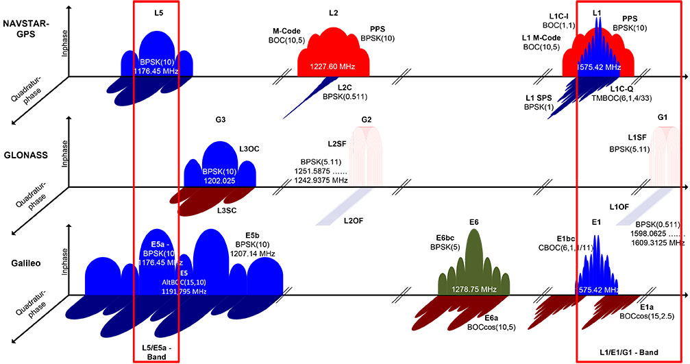
The NAPA chip features a monolithic, single mixed-signal chip implementation of a multi-system, multi-band analog front-end and the related digital baseband core, including an embedded processor. The NAPA chip can be used as a stand-alone GNSS sensor, because no additional components are required to obtain a PVT solution. The ASIC was implemented in a low-power technology and adopts some ad-hoc low-power architectural features. In regard to costs, an ASIC solution is more convenient than FPGA, provided the non-recurring engineering costs (NRE) are amortized by the amount of chips manufactured and sold. The NAPA chip supports multi-system (GPS, Galileo, and GLONASS) and multi-band (GPS/Galileo L1/E1, L5/E5a, GLONASS G1) processing. Figure 1 shows the frequency band being selected for receiving and processing in the NAPA chip. With two fully deployed GNSS — GPS and GLONASS — NAPA chips can already be used in many commercial applications. Thanks to the spectral overlay of the GPS L1/L5 and Galileo E1/E5a signals, the chip is also ready for Galileo. The frequency selection features both the narrow-band legacy signals L1/G1, which can be used for fast acquisition. For highest tracking accuracy, the wideband GPS L5 and Galileo E5a BPSK(10) modulated signals can be utilized.
Figure 1. GNSS signals received and processed by the NAPA chip.
The higher accuracy is obtained primarily by the attenuation of the ionospheric error. The ionosphere is a dispersing media that can introduce a bias error between 1 and 20 m. Forming a linear combination of two independent frequency-band measurements, the ionospheric bias can be measured and almost completely removed. In addition, Precise Point Positioning and Wide/Narrow-laning combinations are possible, thanks to the second received frequency band. The first allows for the combination of precise satellite positions and clocks with multi-frequency measurements, providing cm/dm solutions. The second adopts fast ambiguity solutions for carrier-phase positioning and cycle-slip detection.
In this article, we present the NAPA chip in detail. We describe the architecture of the analog front-end and its digital counterpart and the innovative features of each. Then we provide details about chip implementation, manufacturing, and test setup. Finally, we present the first verification results and draw conclusions.
Architecture Overview
The NAPA chip architecture, depicted in Figure 2, is composed of two separate blocks integrated on the same silicon die: the analog core provides the functionality of a two-frequency radio-frequency (RF) front-end, whereas the digital part implements the main GNSS processing tasks, including the correlator channels and an embedded processor, and takes care of the RF front-end control. The interface between the two blocks is completely digital and provides synchronizers to ensure a valid clock domain crossing (CDC).
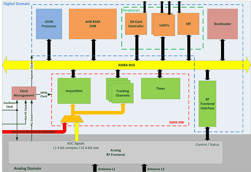
Figure 2. Overall NAPA architecture with emphasis on the digital core blocks.
Analog Front-End. The analog RF front-end supports the simultaneous reception of GPS L5 / Galileo E5a and GPS L1 / Galileo E1 / GLONASS G1 signals as well as modes where only one reception path is activated.
Both passive and active GNSS antennas are supported, thanks to integrated low noise amplifiers (LNA). There are two separate signal reception paths for the two frequency bands. The L1/E1/G1 path is characterized by a quasi-zero-IF conversion that mixes the middle frequency between L1/E1 and G1 to zero frequency. The L1/E1 reception bandwidth is up to 14 MHz so as to incorporate the MBOC modulations of Galileo E1 and future GPS L1C signals. A programmable automatic gain control (AGC) controls the complex analog baseband signals before they are digitized with a 4-bit dual-channel analog digital converter (ADC).
The second reception path receives an L5/E5a signal with up to 20 MHz bandwidth for the BPSK(10) modulated signals. This path uses a low-IF architecture. The signal is down-converted to an intermediate frequency (IF) of 15.345 MHz. The image frequency is suppressed by a polyphase filter. The real-valued analog signal is controlled by an AGC and converted to the digital domain using a single 4-bit ADC. A common phase locked loop (PLL) is used with specific L1/E1/G1 and L5/E5a dividers to generate the mixers’ local oscillator (LO) frequencies. The PLL loop filter is integrated on-chip to minimize external elements. Moreover, automatic filter and voltage-controlled oscillator (VCO) calibrations are included to mitigate process tolerances. The PLL can handle input clock frequencies between 10 and 80 MHz with a recommended clock frequency of 36.115 MHz.
An SPI core was implemented on the front-end part to facilitate control of the different front-end features. This means it is possible to tune the PLL, to switch off a complete front-end path if the second frequency band is not used and to activate different on-chip calibration procedures.
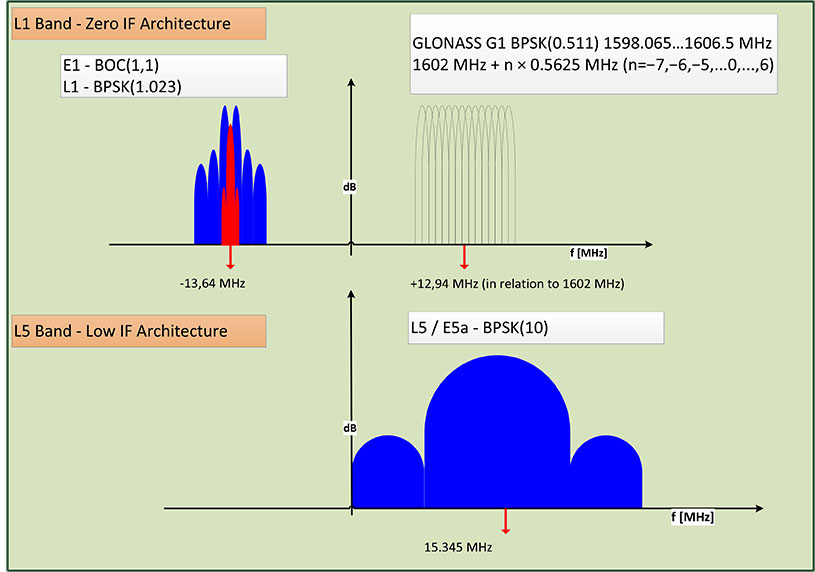
The frequency plan of the front-end is depicted in Figure 3. Due to the quasi zero-IF architecture, the complex L1/E1 baseband signal is located on an IF of -13.64 MHz and the GLONASS G1 frequency division multiple access (FDMA) signals on an IF of +12.94 MHz, with respect to the GLONASS G1 center frequency of 1602 MHz. The real-valued L5/E5a signals are provided by the second ADC and located on an IF of 15.345 MHz.
Figure 3. RF front-end frequency plan.
The ADC samples are generated with a frequency of 74.4871875 MHz for both the single channel L5, as well as for the dual-channel L1/E1/G1 ADCs. The ADC clock is also directly connected to the baseband digital core and is used as the main clock for the GNSS hardware modules. The embedded processor in the digital core receives a second clock, which is twice as fast as the GNSS hardware one.
Digital Baseband SoC. The baseband is characterized by a system-on-chip (SoC) architecture based on a SPARC-compatible 32-bit LEON2 microprocessor running at approximately 150 MHz. The GNSS functionality, including acquisition and tracking, are implemented using dedicated hardware modules.
The processor’s primary functions are to correctly configure the RF front-end and control the different parts of the receiver. In particular, it triggers acquisition, initializes, and starts the tracking channels with the signals detected during acquisition and takes care of closing the frequency/phase/delay locked loops (FLL/PLL/DLL) used for signal tracking. The tracking loops have strict real-time constraints; communication between the channels and the processor features a high-speed infrastructure.
Structurally, the processor is connected to a hierarchical on-chip Advanced Microcontroller Bus Architecture (AMBA) composed of a high-performance bus (AHB) and a peripheral bus (APB). The AHB provides a direct connection between the processor, the real-time GNSS modules, and the system memory, a monolithic 1 MByte block that hosts the main program at run-time. Different programs can be loaded if needed by using the external SD-card interface.
In addition to the processor, there are four additional AHB masters: the bootloader, the SD-card controller, the real-time GNSS modules, and the on-chip processor debugger. The bootloader is in charge of the bus control at system start-up. The SD-card controller has integrated direct-memory access (DMA) capabilities to move data between the SD card and the system memory. The real-time GNSS modules can write the tracking results directly to the system memory. Finally, the integrated processor debugger allows real-time debugging and is used mainly in the verification phase. The APB provides a connection to generic peripherals, and control and status interface of the GNSS modules without real-time constraints, as well as the control and status interface of the RF front-end. Since the GNSS modules operate in a separate clock domain that runs at half the frequency of the processor domain, some synchronization logic is necessary to ensure correct CDC.
The adoption of an SoC architecture provides higher flexibility than conventional static hardware solutions. In addition to typical GNSS applications, the user can also implement some signal monitoring and processing algorithms in software. The eCos-embedded operating system is provided to ease software development.
Generic Peripherals. The digital core is equipped with several peripherals that enable the communication with the outside world. The two separate universal asynchronous receiver/transmitter (UART) interfaces can run at 115.2 kbps. A dedicated serial peripheral interface (SPI) master is also provided with a maximum of 10-MHz clock frequency. For example, these interfaces can be used to provide NMEA data to some external display device or raw data (pseudoranges, code phases) in order to calculate a PVT solution. It is also possible to directly access the measurements generated from the correlator hardware and to control the tracking NCOs, which means users can choose their own algorithms for the loop closure. A possible application is the realization of vector-delay tracking using the NAPA ASIC and an external processor.
The SD-card interface facilitates the loading and storage of large amounts of data, for example, memory codes and almanacs. The possibility of making signal snapshots periodically and saving them to an SD card for later analysis has also been foreseen. This could be useful in special applications in which the receiver hardware is not accessible to the user all of the time.
In addition, 10 general-purpose I/O pins (GPIO) are provided. They can be controlled via software and can provide a very basic interface (for example, to connect to external LEDs or switches).
Acquisition Module. The acquisition module adopts a parallel code phase search in the Fourier domain by using a 16-k Samples Fast Fourier Transform (FFT) core. The adopted algorithm is known as parallel code-phase search.
The L1/E1/G1 signals coming from the front-end are first filtered and then sent to the acquisition module to allow a fast detection of the satellites in the L1/E1/G1 bands with their respective code delays and Doppler frequencies. The acquisition of GLONASS G1 FDMA signals is possible thanks to a software-configurable hardware mixer that can be set with the different G1 carrier frequencies. No direct hardware acquisition is supported for the L5/E5a band signals. The tracking of L5/E5a band signals is possible by performing a hand-over from L1/E1 band or a Tong search using the tracking channels.
The acquisition process is performed iteratively over all the possible satellites and over a set of Doppler values. These values are obtained by dividing the complete range of possible Doppler variations into bins. The smaller these bins are, the more accurate the acquisition result, but the more time is required to complete the entire process.
The acquisition has an additional layer of configurability because of the adoption of coherent and incoherent accumulations. These accumulations are supported in hardware but are completely software-controlled. This provides another possibility for achieving higher accuracy, but at the cost of a larger execution time due to an increase in the amount of accumulations.
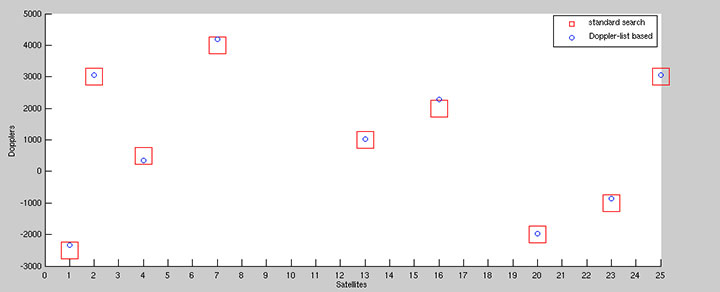
To speed up acquisition, we introduced a dedicated logic based on a novel patented algorithm. With this algorithm, we are able to detect the Doppler of the L1/E1 satellites present in the signal with an accuracy of 2 Hz. By performing this Doppler search step before the actual acquisition, we are able to generate a list with Doppler values that can be used instead of the bins. This gives more accurate results thanks to the algorithm’s inherent accuracy (see Figure 4) and allows a reduction in the acquisition time since the amount of Doppler values are usually smaller than the bins. Another advantage of this algorithm is the possibility to detect the transition to an indoor context (such as where there is a lack of satellite signals) by simply looking at the Doppler list, without performing any acquisition.
Figure 4. Comparison between standard and Doppler-list based acquisition of an L1 signal.
A single iteration step for the acquisition of a GPS L1 signal requires no more than 1 ms for each accumulated epoch. To achieve a good compromise between accuracy and speed, we typically use four epochs of incoherent accumulation, which means approximately 4 ms execution time. For Galileo L1 with four incoherent accumulations, an iteration step takes approximately 16 ms. This time has to be multiplied by the number of satellites and bins to estimate the execution time of the complete process.
Integrated Acquisition Memories. The acquisition module is characterized by dedicated memory blocks used for the fast FFT processing. It also provides the possibility to use these on-chip memories to store a snapshot of the incoming signals. In particular, we can store up to 81,920 samples of raw data for the complex L1 and real L5 IF signals for further analysis or processing, even off-chip. This enables sophisticated spoofing detection methods, for example, as well as interferer detection and characterization methods. Spoofing detection can be implemented by monitoring the 2D-acquisition search space. Interferer detection and characterization can employ short-time Fourier transforms (STFT) on the snapshot.
Using the chip as a simple snapshot receiver without having to use the on-chip dedicated GNSS hardware is also a possibilty. For this purpose, the integrated peripherals like UART and SPI ports are provided as interfaces.
Tracking Module. The 40 versatile tracking channels can be mapped to any combination of GPS, Galileo, and GLONASS signals on the two reception bands. One possible combination would be to track 10 GPS and 10 Galileo satellites simultaneously on both L1/E1 and L5/E5a bands. Alternatively, the user can include GLONASS signals by using fewer GPS / Galileo combinations. The assignment of these tracking channels to the actual GNSS signals can be changed at run-time in order to adapt to different reception situations or to assist the selected signal processing methods.
Each channel is characterized by a five-tap correlator. For the BPSK modulated signals without side peaks, such as GPS L1/L5, Galileo E5a, and GLONASS G1, we use only three values (early, late, and prompt). For Galileo E1 BOC(1,1) signals, five values are foreseen (very early and very late in addition to the previous), so that false peak lock conditions can be detected and a bump-jumping algorithm can be applied. The switch between these modes can be done at run-time and determines the amount of correlation values to be exchanged between correlators and processor.
Low-Power Features. The GNSS modules operate in their own clock domain. This clock domain is divided in clock-gated regions. There is a common region for the bus interfaces, one region for the acquisition, and one for each tracking channel. This allows a fine-grain shut-down of the GNSS modules that are not currently in use. For example, the acquisition can be deactivated when there are enough signals in tracking or the unused tracking channels can be disabled. This allows a reduced power consumption for the idle modules. This activation/deactivation procedure is controlled through a set of registers connected to the APB and is performed via software.
External Front-End Interface. To allow for more flexibility, we provided an additional RF front-end interface. The interface is also depicted in Figure 3. This interface features one 2-bit complex and an additional 2-bit real input, as well as a clock input. The user can decide to directly connect the digital baseband core to an external RF front-end with compatible sampling rate parameters, and exclude the on-chip RF front-end. This makes it possible to use the NAPA chip for validating other RF front-end devices, or it can be adapted to special customer needs.
Boot-Up Sequence. The SoC includes a hard-coded bootloader that is in charge of the bus control at start-up. In this phase, the processor is switched off. The bootloader loads a 24-kByte program from the SD-card to the system memory and starts the processor. In this phase, the processor runs with the external oscillator clock. Having performed the RF front-end initialization, the processor can switch to the front-end PLL generated processor clock that runs at approximately 150 MHz. This switch is completely transparent to the processor. Then the actual main GNSS receiver program is loaded into the system memory and executed.
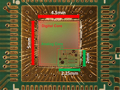
The NAPA Chip
The NAPA chip has been manufactured in a low-power 1.2 V 65 nm TSMC technology. The 4.5 mm x 5.0 mm chip die was mounted in a QFN68 package; first test samples are available. The core requires a 1.2 V power supply, the pads 1.8 V. Figure 5 shows a picture of the die and its interconnections. The two parts, the analog core and the digital baseband, are clearly distinguishable. The chip is currently in the verification phase.
Figure 5. NAPA chip.
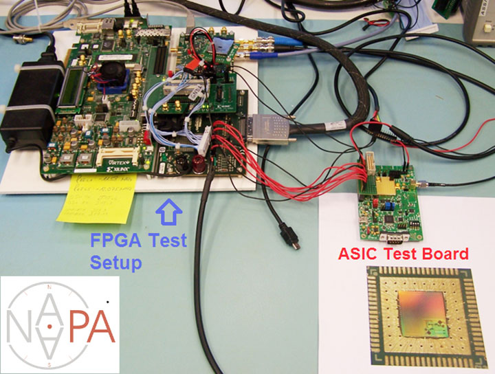
Within the project, the development and testing of the NAPA design was carried out on basically two platforms. During the hardware development phase, the baseband core has been prototyped on a FPGA device and tested using a special file-player setup, as explained in the following section. Having taped out the chip and received the first samples from the foundry, a test board has been developed in order to verify NAPA chip functionality.
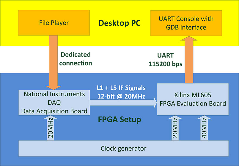
FPGA Test Setup. In the development phase, the NAPA baseband core has been implemented on a Xilinx Virtex6 FPGA device. A Xilinx ML605 development board has been used for the test setup. The main limitation of the testing in this phase was the lack of an analog RF front-end prototype. In order to make early testing of GNSS functionality possible, we adopted a file player developed by Fraunhofer IIS in a previous project. This file player uses a desktop PC to reproduce a digital signal data-stream stored in a binary file on the PC. The stream is sent through a dedicated interface to a commercial digital acquisition board. This board receives a clock synchronized with the baseband core’s clock in the FPGA and delivers the signals directly to the FPGA pins. The complete setup is depicted in Figure 6. The setup in use can be seen on the left part of the opening figure.
Figure 6. FPGA test setup.
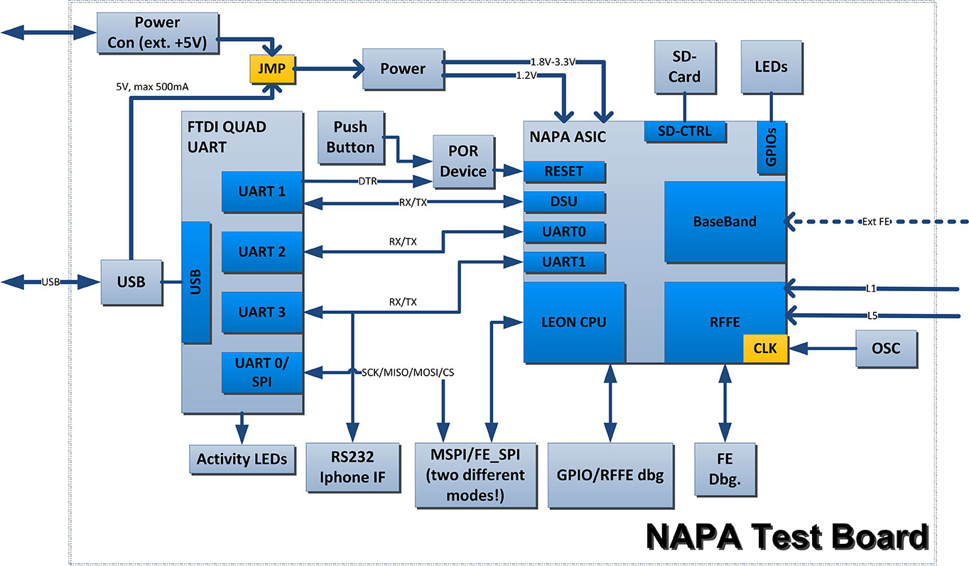
Test Board. In the verification phase, which is currently ongoing, the first unpackaged test chip dies have been glued directly to the test PCB and bonded on board without any housing. After receiving the packaged chips, the QFN68 could be regularly soldered on the PCB. A block diagram of the board is depicted in Figure 7. The board hosts the typical switch buttons and LEDs for quick control and status detection as well as some specific interfaces. The clock can be provided through a dedicated SMA clock connector as well as a discrete oscillator. Two sub-miniature push-on (SMP) connectors are also provided for separate the L1 and L5 antenna inputs. The two UART ports, the debugger UART, and the SPI master port are connected using a FTDI chip. This chip allows the simultaneous connection of these ports to a desktop PC’s USB port. A parallel connector is provided to interface external front-end ADC signals and clock. The GPIOs are accessible through the same connector. A dedicated socket is added for a mini-SD card.
Figure 7. Block diagram of NAPA test board.
Preliminary Results
The chip on the test board was first tested using the same file player of the FPGA setup. This way, we could evaluate the correct functionality of the digital baseband core without the need to activate and configure the on-chip front-end. After the successful tests, we focused on the on-chip front-end configuration, and we used the antenna connectors to provide valid GNSS signals. We tested the chip using three different configurations: a GNSS signal simulator, a static roof antenna, and a small active patch antenna.
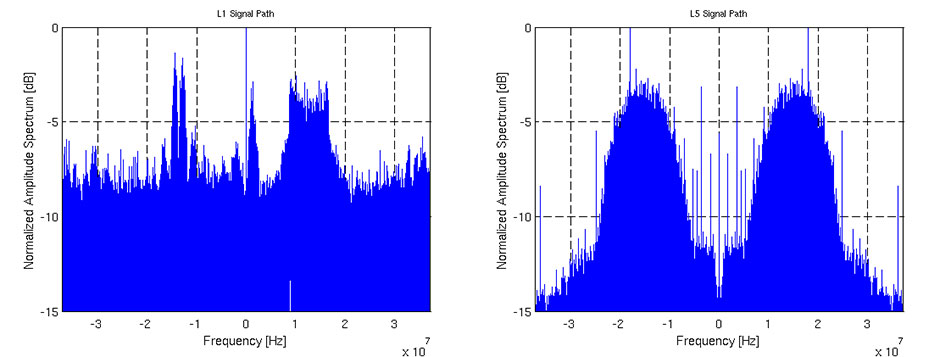
In the three configurations, we successfully acquired GPS L1 and Galileo E1 signals. We were also able to perform tracking on GPS L1 and L5I, as well as Galileo E1b and E5aI. Figure 8 shows the spectrum of a snapshot of L1 and L5 paths made using the on-chip dedicated snapshot hardware and sent through the UART port with a dedicated binary protocol for offline processing. For this special test, we used an arbitrary waveform generator to provide noiseless Galileo and GLONASS signals in the L1 and L5 frequency bands, supported by the NAPA chip. After performing a FFT of the two snapshots, we can clearly see these signals. In the L1 plot, the E1b signal is present in the negative frequency range with the two peaks typical of the BOC(1,1) modulation. The FDMA GLONASS G1 is in the positive frequency range with its trapezoidal characteristic. It is also possible to see a side lobe of the E1a BOCcos(15,2.5) in the proximity of the zero frequency. In the L5 plot, we can see the main peak of BPSK E5a signal on the right and its mirrored image on the left, due to the fact that L5 signal path is real.
Figure 8. Spectrum of L1 and L5 band showing a Galileo E1 and E5a signal.
Acknowledgment
This project has been funded by the Bundesministerium für Bildung und Forschung (BMBF) (German Federal Ministry of Education and Research), which is gratefully acknowledged.
A number of factors are holding the proximity marketing/indoor positioning markets back: standardization issues, consumer acceptance/privacy, retailer awareness and the technology itself. However, as one location executive put it, it may be the one way that retailers with brick and mortar stores can compete with Amazon and other online giants.
Indoor location and proximity marketing may be the way large and small brick and mortar stores can compete with online retailers in the future, said panelists at the New York Place conference, held July 22. But all of this indoor location market talk doesn’t mean much if consumers don’t find a need for it.
“I am in an aisle at a grocery store and you sent me a coupon for cat food, and I don’t have a cat, I am not going to be interested. The retailer gets to own the data by providing a great experience to the consumer, not the spontaneous ‘you are in a store — here’s some information,’” said John Dempsey, Datalogix head of mobile and video.
While having a broad picture of a consumer’s “mobile moment” is important, there is something to be said about bombarding a consumer with too many location-based applications, said Doug Kilponen, Wanderful Media chief operating officer. “There are a limited number of apps consumers are willing to have, but not 200 different ones. It’s one thing to have an app for say, Target, but trying to find out what is broadly available during shopping makes shopping too much work,” he said. “Trying to find out what’s available becomes too much work as there are too many options [for the consumer].”
From a retailer’s perspective, they want consumer’s data, and will share it with partners, but they also want control, said Catherine Lindner, Shelfbucks chief marketing and merchant officer, who was an executive at Walgreens. “If you think about your own shopping behavior, there is only a few places you actually go to and spend money — a grocer, drug store. That retailer wants your data, and it makes sense,” she said. “How do we spend the money to grow the business? The idea that there is one bucket of money to transfer is not going to happen.”
One company says that consumers don’t want to be “advertazed” by retailers. “Their job is to show you Calvin Klein, but sometimes there is not enough information or context. They hijack moments, rather than create them,” said Scott Townsend, Urban Airstrip director of agency programs.
Still, retailers are increasingly using indoor location as part of their mobile strategies. Jewelry chain Alex and Ani has three beacons in their Boston and New York stores, said Ryan Bonifacino, Alex and Ani vice president, digital strategy. “We really want to prove that this [indoor location] can really work. We really want to get in front of people who wouldn’t have discovered us,” he said.
Indoor Location Standardization? What Standardization?
Like any new technology and market, industry standardization will have growing pains, and a lot of the problem may be with the retailers, said panel members. “There are issues with standardization. If Walmart puts a [indoor positioning] in to its store — they don’t care if it works anywhere else,” said Don Dodge, Google developer advocate.
Indoor location is the classic chicken-before-the-egg situation, said Chris Goodall, Trusted Positioning founder and CEO. “There currently are no standards for indoor [positioning], maybe we need it. Databases are not standardized,” he said.
A lot of the reason that standardization has not be resolved is that no big application, the old killer app, has appeared. “Indoor is something that has not emerged yet, it’s a long tail story,” said Dan Ryan, ByteLight co-founder and CEO. “Every location company is trying to build a network — and naturally attract developers.”
Making Proximity and Indoor Location Relevant to Retailers
Some retail chains like Walgreens have used indoor positioning technology for years and are considered some of the major early adopters. However, making consumer-purchasing behavior data relevant to retailers is the only way for indoor marketing to take off.
The concept of geofencing each store has been tested in several locations. One company envisions an image of a celebrity greeting consumers in a store with an offer. “Walgreens focused on not invading people’s privacy. But they basically asked users, what’s important to them when they walk into a store,” said aisle411 founder and CEO Nathan Pettyjohn. “[Bluetooth Low Energy] beacons can do this very elegantly. When a consumer walks through a store, perhaps they see a celebrity popping out to greet them.”
In many successful mobile marketing campaigns, all have a common theme — proximity components always enhance sales, said James Smith, Verve chief revenue officer. “Every one of our studies says it drives sales. Sometimes we hear that geofences don’t work — my answer to that is they are in the wrong places,” he said. “A person can go into a place 15 days later and a beacon locks on them — the retailer is happy because it works. Consumers are more empowered because they have a research device in their hand to go where they want to go.”
Case Study: Walkbase
A Finland-based company is delivering market research to retailers that examines consumers’ in-store shopping behavior and loyalty patterns. Walkbase, which signed a deal with Helsinki airport operator Finavia, started in 2007 when it spun off from an indoor location company.
“It’s a retail tool that analyzes indoor performance of marketing campaigns and [sales] conversion. It measures when consumers come into a store — do they bounce out or are they engaged?” said Juha Mattsson, Walkbase vice president, sales and marketing. “A retailer can launch a campaign that is affected by a consumer’s indoor journey. Whether that is through coupons, or not, as some retailers don’t want that.”
Mattsson says that the company is operating primarily in Europe — and is waiting for what indoor technologies will win. “It is just a matter of time before the market takes off. Retailers are very interested in these types of consumer spending analytics,” he said. “We will be launching a U.S. white paper on in-store optimization as it’s all about education. We also are rolling out a version 2.0 of our product in the third quarter.”
In other LBS news:
According to published reports, Michael Halbherr, CEO of Nokia’s HERE mapping unit, will be stepping down. Halbherr, who is based in Berlin, steps down after eight years at the company. As recently as 2012, HERE, then called Navteq, had been losing money but had stabilized recently. Cliff Fox, HERE senior vice president, will be acting CEO until a replacement is found.
I will be covering CTIA’s Super Mobility Week in Las Vegas, Sept. 8-11. To arrange an interview with me for Wireless LBS Insider, or to submit press releases, contact me at [email protected].
CSR plc and OriginGPS have announced a series of high- performance GNSS modules using CSR’s SiRFstarIV and SiRFstarV product lines.
The new modules are 70% smaller than current solutions and deliver a 30% reduction in Time To First Fix (TTFF), making them ideal for health and fitness trackers, sports watches, medical devices, wearable action cameras, and digital still cameras. All modules, including the newly released 7 x 7 millimeter Multi Spider (ORG4572) solution, integrate the LNA, SAW filter, TCXO, RTC crystal and RF shield.
“To accelerate market adoption of location technologies in wearable devices and cameras, manufacturers must minimize the embedded GNSS module size without compromising on performance, sensitivity, or power consumption,” said Anthony Murray, senior VP, Business Group at CSR. “By leveraging CSR’s industry-leading GNSS solutions and collaborating with OriginGPS on module development, we have achieved this objective.”
The OriginGPS modules offer high sensitivity resulting in shorter autonomous and aided TTFF, better navigation stability, and higher accuracy in harsh environmental conditions. In real-life testing of the module in camera applications, TTFF performance improves by over 30 percent compared to other solutions. The module also delivers TTFF results in less than one minute over 90% of the time (cold starts).
In addition to its small footprint, the GNSS module’s ultra-fast geotagging capability dramatically improves the consumer experience. The GNSS antenna module’s outstanding sensitivity and OriginGPS’ proprietary Noise Free Zone (NFZ) technology for faster position fix and navigation stability provides geo-tagging availability even under challenging satellite signal conditions such as low signal areas, under dense foliage, in urban canyons, and during motion-based activities. Battery life is considerably extended as a result of CSR’s breakthrough low power Push-to-Fix (PtF) technology, which rapidly establishes a valid position fix enabling the module to hibernate for longer periods of time. Push-to-Fix is an intelligent periodic low power mode that adaptively changes power depending on the operating environment and motion conditions. Advanced algorithms and a powerful on-chip DSP processor maintain high accuracy (QoS) while achieving the lowest power level possible for the given environmental and motion conditions.
“As the wearable technology and action camera markets continue to grow, we must ensure that our solution meets the market’s need for high performance and small form factor GNSS modules,” says Gal Jacobi, CEO of OriginGPS. “It is our privilege to partner with CSR and its excellent engineering team to meet the market’s need. CSR’s leading multifunction semiconductor platforms and OriginGPS’ miniaturized high performance modules create a unique value proposition for customers in these markets.”
OriginGPS modules are currently in mass production, and additional information can be found at www.origingps.com.
All of us in the GPS industry know someone who only thinks of GPS as a feature of their smartphone. You might direct them to a new YouTube video presented by the U.S. Air Force, which summarizes the worldwide role of GPS. It also touches on the GPS modernization program and new signals.
The seven-minute video explains in simple terms how important GPS has become to everyday life — for aircraft and ship navigation, global financial transactions, precision agriculture, weather forecasting, disaster relief, and, of course, smartphones.