Services of the Quasi-Zenith Satellite System (QZSS) officially started on Nov. 1, according to a statement from Japan’s National Space Policy Secretariat, Cabinet Office.
Government and industry hope the turn-on will generate new services worth nearly 5 trillion yen ($44.4 billion) by 2025 as players like SoftBank Group, Mitsubishi Electric and Hitachi plan applications in automated driving, farming and more.
“Our lifestyles would be impossible without GPS,” Prime Minister Shinzo Abe said at initialization ceremony marking the start of the service. The Michibiki satellite constellation, known officially as QZSS, would let Japan turn “a new page in history,” he continued.
The system keeps at least one of the current four Michibiki satellites over Japan at all times, offering an advantage over GPS-only services with a precise bird’s-eye view uninterrupted by mountains or tall buildings. With special receivers, the satellites can narrow margins of error to 10 centimeters.
The signal is free for anyone with a device capable of receiving the signal.
Prime Minister Shinzo Abe delivers a congratulatory address as QZSS is officially launched. (Photo: Japan Cabinet Public Relations Office)
Japan’s cabinet and other government bodies have invested 120 billion yen in QZSS. Expectations are particularly strong for applications in the rapidly advancing field of automated driving, with some businesses estimating the market for positioning services in that field alone at roughly 500 billion yen.
QZSS offers lane-level positioning capability, is a key step towards auto autonomy.
Michibiki means guidance in Japanese. In his remarks, Abe said the satellite-based augmentation system (SBAS) “will guide us to Society 5.0, the society of the future. There are high hopes for the ever greater use of this satellite system in a wide range of fields. The government aims to expand the system to a seven-satellite constellation by FY2023, with the goal of achieving an even more stable positioning service.
“More than 10 years have passed since its conception. I am sure that taking on this challenge, the first of its kind in the world, must have required much hard work. I would like to express my utmost respect for the efforts of the engineers responsible for the development and all those involved with this project.
“To what degree will the ‘Michibiki’ change our lives? I hope to follow its progress with great excitement, together with you all.”
This month we bring you a guest column by Steffen Thoelert, André Hauschild, Peter Steigenberger and Oliver Montenbruck of the German Aerospace Center (DLR) and Richard B. Langley of the University of New Brunswick.
UPDATE:Since Sept. 10, continuously operating DLR receivers in Sydney, Australia, and Chofu, Japan, have been reporting measurements from QZSS satellite J07, which, according to the QZSS Interface Control Document, is the geostationary satellite QZS-3.
The second satellite of Japan’s Quasi-Zenith Satellite System (QZSS) has started transmitting navigation signals. QZS-2, or Michibiki-2, was launched on June 1, 2017, and joins its predecessor QZS-1 (Michibiki-1), which has been in orbit since September 2010.
Both satellites have been placed into inclined geosynchronous, elliptical orbits, which enable extended satellite visibility periods over Japan and are characteristic features for this regional navigation system.
The third satellite, QZS-3, was launched on Aug. 19, 2017, into a geostationary orbit. If all goes according to plan, a fourth satellite in an eccentric orbit will follow by the end of this year and complete the constellation.
QZS-2 Signal Tracking
It is not straightforward to tell when QZS-2 started signal transmission exactly. About four weeks after launch, on June 27 between 10:17 and 12:37 UTC, several Septentrio PolaRx GNSS receivers in the Asia-Pacific region recorded continuous L5 observations. About one week later, on July 4 shortly after 03:02 UTC, Javad and Trimble receivers picked up L1 C/A and L5 signals from QZS-2 for a few seconds. Then again, between 23:03 UTC on July 6, and 01:36 UTC on July 7, several receivers intermittently tracked the L1 C/A, L2C and L5 signals. Finally, on July 10, starting at approximately 01:03 UTC, these three signals were continuously tracked until approximately 04:00 UTC on July 12. Up until Aug. 1, signal tracking had remained intermittent, but has been stable since. This was presumably the result of interruptions in the signal transmission due to test activities.
Figure 1. QZS-2 signals tracked by GNSS receivers in Chofu, Japan, (top plot) and Sydney, Australia, (bottom plot). The plots depict the measured C/N0 for L1 C/A (black), L2C (red) and L5 (green) together with the observed pseudorange (grey). The frequent discontinuities in the pseudorange are due to the receiver clock adjustments. Both receivers exhibited a short tracking outage at approximately 06:00 UTC. The interruption in tracking at Chofu around 08:00 UTC is due to the low elevation angle of the satellite.
The plots in FIGURE 1 show QZS-2 signals as tracked by GNSS receivers in Japan and Australia on July 10. The two first sets of broadcast messages were transmitted on July 16 at 6:00 and 7:00 UTC. Regular transmission of broadcast ephemerides started on July 27 at 22:00 UTC, but deviations from the hourly update rate still occur from time to time.
Identical or Fraternal Twins?
At first glance, QZS-2 seems like a look-alike of QZS-1, but there are many differences between the two spacecraft. Most apparent is the presence of an additional auxiliary antenna. Like QZS-1, QZS-2 transmits its navigation signals on the L1, L2, L5 and L-band Experiment (LEX) frequencies through the main antenna, while the augmentation signal L1S (formally known as Submeter-class Augmentation with Integrity Function or SAIF) is transmitted from a separate antenna. However, the new L5S signal, which is introduced with QZS-2, is transmitted with yet another antenna.
The new satellite also has a shorter “wingspan” of only 19 meters, since it is equipped with two solar panel segments on each side, compared to three segments for QZS-1 with a width of 25.3 meters. The second QZSS satellite also follows a different attitude model: Unlike QZS-1, which switches between yaw-steering mode and orbit-normal mode depending on the sun’s elevation angle with respect to the orbit plane, QZS-2 always remains yaw-steering except for short periods of time when orbit maneuvers are performed. Further differences will become apparent in the analysis of the signal spectra in the subsequent sections.
The Cabinet Office of the Government of Japan, which oversees QZSS as a national undertaking, has published QZSS satellite metadata information on its official website. At the time of writing, only one document for QZS-2 is available, which contains information about the satellite’s properties such as mass, dimension, attitude law and reference frame, but also antenna and laser retroreflector positions, antenna phase-center offsets and variations as well as signal group delays.
Additional documents containing metadata for QZS-1, -3 and -4 and further information about QZS-2 are in preparation.
Rubidium Clock
FIGURE 2 illustrates the stability of the QZS-2 rubidium atomic frequency standard (RAFS) by means of the Allan deviation (ADEV). Data from a global network of 150 GNSS stations was processed to estimate GPS and QZSS satellite orbit and clock parameters.
Figure 2. Allan deviation of the rubidium atomic frequency standards of GPS Block IIF satellite G32, QZS-1 (J01) and QZS-2 (J02).
However, whereas about 60 of these stations provide QZS-1 observations, QZS-2 is only tracked by 13 stations. ADEV values for QZS-1, QZS-2 and a GPS Block IIF satellite were computed from a daily solution for Aug. 3 with 30-second clock sampling.
At an integration time of 100 seconds, the QZS RAFS reaches an ADEV of better than 3 × 10-13.
At longer integration times, the QZS-2 clock almost reaches the stability of the GPS Block IIF RAFS.
Based on this preliminary analysis for only one day, the QZS-2 clock seems to perform as expected. The larger ADEV values compared to QZS-1 for integration times up to 1,000 seconds might be attributed to the significantly smaller number of tracking stations contributing to the QZS-2 clock solution. The quality of the clock solution will improve as soon as more stations are able to track QZS-2.
Signals with High-Gain Antenna
Complementary to the receiver measurements and analysis, the German Aerospace Center (DLR) has also recorded raw spectral and in-phase and quadrature (IQ) data of QZS-2 to get further insights into the transmitted signal structure and initial signal quality. FIGURE 3 shows a spectral measurement of the complete GNSS L-band frequency range, which shows the signal transmissions of QZS-2 in the L1, L2, L5 and L6 bands. The signal was captured with DLR’s 30-meter high-gain antenna at Weilheim, southwest of Munich, operated by DLR’s German Space Operations Center.
Figure 3. QSZ-2 L-band normalized power spectra recorded at Weilheim, Germany, on July 18, 2017 at 20:43 UTC.
This first view of the signal transmission shows a good spectral shape, appropriate band filtering and no out-of-band unwanted spurious emissions of the satellite. For further analysis, we looked closer at each signal-band spectrum and performed IQ-sample recording.
Comparing the QZS-2 spectra to that of QZS-1, we see differences in the signal structure for the L1 frequency band.
Figure 4. QZS-1 and QZS-2 L1 spectral flux density.
FIGURE 4 shows the L1 spectra of both satellites. The additional signal component can be seen at an offset of 6 x 1.023 MHz and 18 x 1.023 MHz from the L1 center frequency of 1575.42 MHz. This is the result of the new L1C-pilot modulation, which is based on the time-multiplexed binary offset carrier (TMBOC) modulation technique using a mixture of BOC(1,1) and BOC(6,1). See here for detailed information.
Another difference is present in the L6 band and can be seen within the signal time domain or the IQ domain. The new satellite transmits two components (one each for the I- and Q-channels) while QZS-1 transmits only one I-component. This observation is fully in line with the QZSS Interface Specification. On QSZ-2, an additional L6 signal component (Centimeter-Level Augmentation Message for Experiments, L6E) is implemented. FIGURE 5 shows the IQ constellation plots of QZS-1 and QZS-2 for the L6 band.
Figure 5. L6 IQ constellation plots for QZS-1 (left) and QZS-1(right).
Source: GPS World
Furthermore, the L5 band IQ plot of QZS-2 exhibits significant differences compared to QZS-1. These differences, which are illustrated in the plots of FIGURE 6, are due to an additional L5S signal transmitted by QZS-2.
Figure 6. L5 IQ constellation plots for QZS-1 (left) and QS-2 (right).
Source: GPS World
The QZS-2 L5 IQ diagram is fairly easy to understand as a coherent superposition of two distinct quadrature signals from two antennas. One signal is the GPS-like L5 signal transmitted from the main L-band antenna, while the other (L5S) signal originates from a new L5S antenna. This is illustrated in FIGURE 7.
Figure 7. QZS-2 L5 IQ constellation plot including demarcation of the L5 and L5S signals.
For illustration purposes, the dashed orange square in Figure 7 relates to the 10 MHz L5 signal, while the smaller red squares are the 10 MHz L5S signal.
A code generator has been setup according the QZSS L5 and L5S interface control document (ICD). An analysis of the correlations of possible pseudorandom noise (PRN) codes resulted in the detection of PRN 194 and PRN 196. Based on the information in the ICDs, PRN 194 is used for L5 and PRN 196 is used for L5S.
The performed code correlation analysis also yields the finding that the L5 signal is approximately 3.5 dB stronger than the L5S signal. Note, however, that both signals have a specified minimum receive power of -157 dBW. Due to the limited visibility of QZSS satellites from the Weilheim ground station, it is not possible to verify this value.
Conclusion
With the launch and activation of QZS–2, the deployment of Japan’s regional navigation system is moving forward again. The launch of a geostationary satellite, QZS-3, took place on Aug. 18. A fourth Japanese navigation satellite is scheduled to launch later this year. With this rapid sequence, the target date of 2018 for the completion of an operational constellation with four satellites is quite realistic.
Steffen Thoelert, André Hauschild, Peter Steigenberger and Oliver Montenbruck are from the German Aerospace Center (DLR).
Richard B. Langley is from the University of New Brunswick and authors the monthly Innovation column for GPS World magazine.
Mitsubishi Heavy Industries Ltd. and the Japan Aerospace Exploration Agency (JAXA) successfully launched a second navigation satellite on June 1.
The H-IIA Launch Vehicle No. 34 (H-IIA F34) delivered into orbit Michibiki No. 2 of the Quasi-Zenith Satellite System (QZSS) at 9:17:46 a.m. (JST) from JAXA’s Tanegashima Space Center.
The launch and flight of the rocket proceeded as planned, and the separation of the satellite was confirmed 28 minutes and 21 seconds after the launch time.
By Oliver Montenbruck, Richard B. Langley, and Peter Steigenberger
Over the past several years, some users of the GPS navigation system have already benefitted from the addition of various new signals in addition to the legacy C/A- and P(Y)-code. With the introduction of the Block IIR-M satellites in 2005, a new civil signal (L2C) was transmitted on the L2 frequency, and a new signal on a new frequency (L5) was introduced as a standard signal with the Block IIF satellites beginning in 2010. These new signals provide direct access to dual-frequency observations and thus enable improved ionospheric corrections for civil, including aeronautical, users. In addition, a new Civil Navigation (CNAV) broadcast message has been defined in the GPS Interface Specifications (IS-GPS-200 and IS-GPS-705).
This message will be transmitted jointly on the L2C and L5 signals and provides a variety of useful new parameters. Compared to the legacy L1 C/A-code navigation message, the CNAV message also offers an increased flexibility concerning the type, sequence, and repeat rate of specific messages.
CNAV messages have already been broadcast over the past two years by the Michibiki (QZS-1) satellite of the Japanese Quasi-Zenith Satellite System (QZSS), which shares many aspects of the GPS signal design. In contrast to this, Block IIR-M and IIF GPS satellites have only transmitted dummy messages so far and a fully operational CNAV transmission is only foreseen once the ongoing modernization of the GPS control segment has been completed.
Triggered by various interest groups, the Global Positioning Systems Directorate has just conducted a first test campaign with live CNAV transmissions on L2C and L5 over the two-week period from June 15 to 29 (see Global Positioning System Modernized Civil Navigation (CNAV) Live-Sky Broadcast Test Plan.) It served as a first opportunity for end users and receiver manufacturers to test the decoding and use of the new messages under a wide range of different configurations.
CNAV messages have a common length of 300 data bits and are identified by a message type number that signifies their contents. The messages presently defined for GPS are summarized in Table 1. For QZSS, complementary messages have been established, which enable, among other features, a rebroadcast of GPS-specific data to QZSS users.
Table 1. Summary of CNAV message types transmitted by space vehicles (SVs). Messages marked by an asterisk were transmitted during the recent CNAV test campaign.
Message
Type
CNAV Message Title
Function/Purpose
0*
Default
Default message (transmitted when no message data is available)
10*
Ephemeris 1
SV position parameters for the transmitting SV
11*
Ephemeris 2
SV position parameters for the transmitting SV
12*
ReducedAlmanac
Reduced almanac data packets for seven SVs
13
Clock Differential Correction
SV clock differential correction parameters
14
Ephemeris Differential Correction
SV ephemeris differential correction parameters
15*
Text
Text (29 eight-bit ASCII characters)
30*
Clock, Iono & Group Delay
SV clock correction parameters, ionospheric and group delay correction parameters (inter-signal correction parameters)
31
Clock & Reduced Almanac
SV clock correction parameters, reduced almanac data packets for four SVs
Other than the legacy L1 navigation message, which adheres to a fixed order of subframes, the sequence of CNAV messages can be varied widely to provide users with an optimized set of low latency information and parameters that change infrequently. As a baseline, the two ephemeris message types 10 and 11 are combined with any of the clock-and-auxiliary data messages (types 30 through 37) to provide users with the orbit and clock data of the received satellites. With a transmission duration of 12 seconds per CNAV message on L2C, a minimum of 36 seconds is required to transfer this information to the user if no other messages are transmitted. On L5, which operates at twice the data rate, a new frame is transmitted once every 6 seconds yielding a minimum of 18 seconds for the broadcast of ephemeris and clock data.
The recent test campaign started at 18:00 GPS Time on Saturday, June 15, 2013, with the transmission of message types 10, 11, 15, and 30 on a first space vehicle (PRN24) and included PRN12 from 18:42 onwards. Other space vehicles were sequentially phased in until all active IIR-M and IIF satellites (except for the recently launched IIF-4 satellite) transmitted CNAV on the supported signals. When the test ended exactly two weeks later (June 29, 18:00 GPST), all participating satellites were transmitting a complex master frame of 15 x 4 = 60 individual messages, which was repeated once every 12 minutes (on L2C). Each minor frame comprised the two ephemeris messages and at least one clock-data message (see Table 2).
Table 2. Sequence of message types in a CNAV master frame.
Message Types
10
11
15
30
10
11
32
33
10
11
12
35
10
11
12
30
10
11
12
33
10
11
12
35
10
11
12
30
10
11
32
33
10
11
15
35
10
11
32
30
10
11
12
33
10
11
12
35
10
11
12
30
10
11
12
33
10
11
12
35
Other messages included a reduced almanac (message type 12) and a text message (message type 15) with dummy content (“THIS IS A GPS TEST MESSAGE.”)
The CNAV data were recorded by selected multi-GNSS monitoring stations of the German Aerospace Establishment (Deutsches Zentrum für Luft- und Raumfahrt or DLR) and the University of New Brunswick (UNB), which were specifically configured to record raw GPS navigation frames in addition to the normal observation data. The stations are located at Singapore (SIN0); Sydney, Australia (UNX2); Maui, U.S.A. (MAO0); and Hartebeesthoek, South Africa (HRAG); as well as Fredericton, Canada (UNB) and are equipped with either Javad Delta-G2/G3TH or NovAtel OEM6 receivers. Following initial validation, the raw and decoded data from the CNAV test will be made available to interested users through the Multi-GNSS Experiment (MGEX) of the International GNSS Service (see http:/igs.org/mgex) to facilitate the development of user software and suitable data formats (such as an extended RINEX navigation message format).
The CNAV orbit and clock data were updated once every two hours and offer a slightly higher bit resolution than their legacy counterparts. However, the accuracy of the ephemeris data has not yet been evaluated nor compared to that of the L1 C/A-code navigation data.
As indicated above, the CNAV data can also provide a particularly compact form of almanac data known as the reduced almanac. It does not offer clock information (that is not normally required for a signal search) and assumes a circular orbit, which reduces the overall accuracy. Still, it can be transmitted (and repeated) in a much shorter time interval than the legacy almanac, which requires a total of 12.5 minutes. Each reduced almanac message (message type 12) provides orbit information for a total of seven satellites and it takes a set of five such messages to convey information for a complete constellation. For the master frame layout described above, the full constellation reduced almanac is repeated twice within 12 minutes on L2C (and half this time on L5).
Novel types of CNAV data not covered by the legacy navigation message include the differential code biases (also known as inter-system corrections or ISCs), which are required for pseudorange-based positioning with signals other than the legacy P(Y)-code (in addition to the established Timing Group Delay parameter or TGD). An overview of TGD and ISC values broadcast by the various satellites participating in the CNAV test is given in Table 3.
Table 3. Differential code biases (in nanoseconds) of GPS Block IIR-M and IIF satellites broadcast during the test campaign as part of the message type 30 CNAV messages.
SV Type
SVN
PRN
TGO
ISC L1CA
ISC L2C
ISC L5I5
ISC L5Q5
IIR-M
48
07
-10.71
-0.84
6.52
IIR-M
50
05
-10.24
-0.32
5.41
IIR-M
52
31
-13.04
-0.55
7.36
IIR-M
53
17
-10.24
-0.84
6.17
IIR-M
55
15
-10.24
-0.47
5.62
IIR-M
57
29
-9.31
-0.76
5.06
IIR-M
58
12
-12.11
-0.76
6.64
IIF
62
25
5.59
-2.07
-5.24
-0.38
-0.87
IIF
63
01
8.38
-2.30
-7.57
0.38
2.15
IIF
65
24
2.79
-0.26
-2.27
2.27
3.70
Another important achievement is the provision of Earth orientation parameters (EOP) in message 32, which provides GPS users with access to the celestial reference frame. EOPs were transmitted during the second test week and updated on a daily basis (see Table 4). Knowledge of these parameters is of particular interest for GPS-based orbit determination and navigation of spacecraft (in low Earth orbit), which is preferably referred to an inertial rather than an Earth-fixed coordinate system.
Table 4. Daily Earth orientation parameters from the CNAV test campaign (pole coordinates and dUT1 (UT1-UTC) time differences and derivatives).
Epoch (GPST)
x_p
(arcseconds)
x_p_dot
(arcseconds per day)
y_p
(arcseconds)
y_p_dot
(arcseconds per day)
dUT1
(seconds)
dUT1_dot
(seconds per day)
June 22, 0:00
0.13517
0.00104
0.39657
-0.00054
0.06341
-0.00046
June 23, 0:00
0.13621
0.00102
0.39604
-0.00056
0.06295
-0.00049
June 24, 0:00
0.13740
0.00101
0.39535
-0.00058
0.06231
-0.00053
June 25, 0:00
0.13815
0.00099
0.39487
-0.00060
0.06164
-0.00063
June 26, 0:00
0.13846
0.00096
0.39443
-0.00062
0.06078
-0.00067
June 27, 0:00
0.13885
0.00094
0.39381
-0.00064
0.06004
-0.00067
June 28, 0:00
0.13947
0.00093
0.39310
-0.00066
0.05909
-0.00063
June 29, 0:00
0.13987
0.00090
0.39246
-0.00068
0.05842
-0.00053
Overall, CNAV offers exciting prospects for improved GPS utilization and users may look forward to the next test campaigns, which will tentatively be conducted once every six months.
As a side note, it should be mentioned that individual satellites could be observed to transmit various types of non-standard CNAV messages as well as CNAV messages with improper data (such as an invalid week count) after the end of the main test campaign. Various receivers in the MGEX network, which were processing the received CNAV messages internally and which put full confidence in their proper contents, were mislead by such information. During the actual test campaign, all data appeared fully valid and no problems were reported by the stations.
OLIVER MONTENBRUCK is the head of the GNSS Technology and Navigation Group at DLR’s German Space Operations Center in Oberpfaffenhofen, Germany.
RICHARD B. LANGLEY is a professor in the Department of Geodesy and Geomatics Engineering at the University of New Brunswick, Fredericton, New Brunswick, Canada.
PETER STEIGENBERGER is a staff member in the Institut für Astronomische und Physikalische Geodäsie of the Technische Universität München (TUM) in Munich, Germany.
The Japan Aerospace Exploration Agency (JAXA) has controlled the orbit of the first quasi-zenith satellite system (QZSS) satellite, Michibiki. JAXA inserted Michibiki into the quasi-zenith orbit from the drift orbit starting on Sept. 21. The final orbit control operation was performed for about 50 seconds from 6:28 a.m. on Sept. 27 JST (Japan Standard Time).
After the operation, JAXA confirmed that the satellite was successfully injected into its preordained quasi-zenith orbit with its center longitude of about 135 degrees through the orbit calculation. The calculation results are as follows.
Michibiki was launched from the Tanegashima Space Center at 8:17 p.m. JST on Sept. 11.
JAXA will carry out the initial functional verification of the onboard mission devices in cooperation with organizations that will perform technological verifications for about three months. These organizations include the Geospatial Information Authority of Japan, the National Institute of Advanced Industrial Science and Technology, the National Institute of Information and Communications Technology, the Electronic Navigation Research Institute, and the Satellite Positioning Research and Application Center.
JAXA provided these definitions of drift and quasi-zenith orbit:
Drift orbit: The last step orbit prior to the quasi-zenith orbit. The orbit altitude and inclination (angle against the equator) are equal to those of the quasi-zenith orbit, but the longitude of the center of the figure-8 orbit is not above Japan. After being injected into the drift orbit, it will take a few days to maneuver the satellite to have its figure-8 center above Japan, thus it will ultimately fly in the quasi-zenith orbit.
Quasi-zenith orbit: While the quasi-zenith orbit has the same orbit period of 23 hours and 56 minutes as the geostationary orbit, it can let a satellite stay over Japan longer by taking an elliptical orbit with higher altitude above Japan and flying in a figure-8 orbit.
As this issue goes to press in late August, the first Japan Aerospace Exploration Agency Quasi-Zenith Satellite System (QZSS) space
vehicle, nicknamed Michibiki, holds steady for a September 11 launch.
QZSS will use multiple satellites in inclined orbits, placed so that one satellite always appears near zenith above Japan, well known for its high-rise cities. The design provides high-accuracy satellite positioning service covering almost all of the country, including urban canyons and mountainous terrain.
QZSS Phase One will validate technological enhancement of GPS availability, performance, and application. Phase Two will demonstrate full system capability using three QZSS satellites, including Michibiki.
The satellites will generate and transmit their own signals, compatible with modernized GPS signals. QZSS also transmits GPS corrections and availability data.
Michibiki Profile. Dual-box shape with wing-type solar-array paddles; overall dimensions, 2.9 x 3.1 x 6.2 meters, paddles extending 25.3 meters; weight approximately 4,000 kilograms; altitude approximately 32,000–40,000 kilometers; inclination approximately 40 degrees;
period, 23 hours 56 minutes.
Compass. In early August, the first Beidou/Compass inclined geosynchronous orbit (IGSO) satellite achieved near-geosynchronous orbit. The mean east longitude of the sub-satellite ground point is currently 117 degrees, 19 minutes (see figure 1). This is one of the first, if not the first, satellite to use such a highly inclined circular geosynchronous orbit.
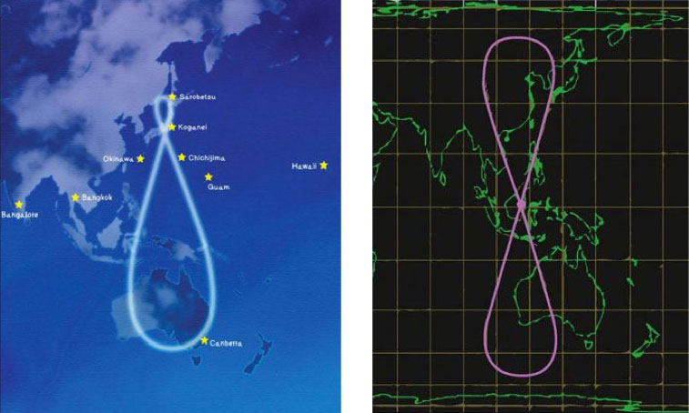
Figure 1. Left, the orbit path of three QZSS satellites will eventually keep at least one of them directly over Japan at all times. Right, the inclined geosynchronous orbit of the fifth Compass satellite, launched in July, has a similar ground track and mission goal.
Multi-GNSS Campaign. An international collaboration is poised to take advantage of a coming proliferation of satellites, led by Compass and QZSS but also including GPS, GLONASS, and Galileo, over the Asia/Pacific region. The website www.multignss.asia/campaign.html states, “The Asia and Oceania region is a unique place where the number of usable modernized navigation satellites will increase much faster than other areas in the world. We will see great improvement of PNT capability and hence there is a great opportunity to try, test, and validate new receiver hardware, algorithms, and applications in order to address user requirements.”
The web page also carries an animation of the availability of more than 100 GNSS space vehicles that will operate over the region in the next decade. An initial campaign workshop in Bangkok, Thailand, in January drew 195 participants from 18 countries. A second workshop is scheduled for November 21–22 in Melbourne, Australia.
GLONASS September. Three GLONASS-M satellites to be launched on September 2 completed pre-launch testing and mating to the upper stage of the booster rocket at Baikonur Cosmodrome. Numbered 36, 37, and 38, the satellites will constitute the Block 42 triad.
GPS III Design: Done. The Lockheed Martin team developing GPS III has successfully completed the program’s Critical Design Review (CDR) phase, two months ahead of baseline schedule. CDR completion validates the detailed GPS III design to ensure it meets warfighter and civil requirements. It culminates many rigorous assembly, subsystem, element, space vehicle and system-level CDR events, validates the overall design maturity of the GPS III space vehicle, and allows Lockheed Martin to enter production phase. Col. Bernard J. Gruber, U.S. Air Force GPS Wing Commander, certified the completion. Lockheed Martin, ITT, and General Dynamics are working under a $3 billion development and production contract for up to 12 GPS IIIA satellites. The team is on track to launch the first GPS IIIA satellite in 2014.
GPS Interface Specs. New IS-GPS-200E, IS-GPS-705A, and IS-GPS-800A documents have been posted to www.gps.gov/technical.
SVN62 Rubidium Clock. The U.S. Naval Research Laboratory issued a preliminary report on the rubidium atomic clock currently in use on the SVN62 Block IIF satellite. While documenting excellent short-term performance, the report notes anomalous fluctuations in the clock signal with distinct 12-hour and 6-hour periodicities. The exact cause has not been identified although it is speculated that the fluctuations are of thermal origin like SVN-62’s L5 phase variance detected earlier. But note that the clock signal analysis relies only on L1 and L2 measurements.
GPS IIF Got Active. The 50th Space Wing’s 2nd Space Operations Squadron formally took over command and control of the first Block IIF satellite on August 26 from the GPS Wing, and the satellite was set healthy on August 27, making 31 healthy GPS satellites on orbit.
Advisory Board Update
GPS World Editorial Advisory Board member Art Gower has been elected a Lockheed Martin Fellow, an honor recognizing pre-eminent technical individual contributors in the company, delivering mission success and vision by undertaking the most difficult technical challenges facing the company and its customers. Art started his career with IBM Federal Systems Division (now part of Lockheed Martin Integrated Systems and Global Solutions) in 1983, developing displays and performing navigation upload and command and control system engineering for the GPS control segment, and becoming chief engineer for the GPS control segment in 1990. He has spent the majority of his career working on GPS, GNSS, and SBAS systems.
Michibiki has more Twitter followers than you and me put together. All of you, and all of me with my 17 followers. Michibiki hit 16,284 when I signed on just now, and she (he?) has not yet even emerged upon the global stage. Perhaps by the time you read this, if the September 11 launch date holds true, s/he will be an orbiting, broadcasting entity.
Michibiki
Why follow a satellite? One might well ask why follow anything or anyone these days. For utterings momentous or vacuous, leavened in lucky moments by a bit of gossip, or an even rarer bit of news. It’s a good bet that Michibiki’s scriptwriters will display more intelligence than the mass of online mouths. Right now it’s hard to tell; they communicate in Japanese, which comes through my browser as so many question marks.
For intelligence is what the Michibiki anthropomorphizing — from the creation of a friendly, pettable caricature to the establishment of a Twitter voice — is all about. Savvy marketing by purposeful people to an audience that they have studied and know well. This goes beyond the cute that large segments of Japan have a fondness for. It has the goal of buliding a solid, sustained client core for location-based services, powered by QZSS signals.
Other places where LBS have failed to take hold — and this means everywhere — despite their vast potential utility, would do well to watch and learn.
As cell-phone text-message readers and e-mail users (could there be a broader market segment, other than people who eat and breathe?) become accustomed to receiving messages from Michibiki, they will subtly but increasingly think of this 4,000-kilogram, 40,000-kilometer high hunk of orbiting metal and circuitry as a personality, and even, a friend. They will be open to suggestions, impressionable and cute-prone teens and twenty-somethings, especially so. This is the next generation of satnav users. Or I should say, this is the Now Generation of satnav users.
Young men and women with places to go and friends to see will remember Michibiki, and call upon her/him often. “My guide will tell me how to get there. With added services, my guide will also track my friends right now, and tell me where they are. My guide can do many more wonderful things for me: here is a list of them.”
By no means do I suggest that the U.S. GPS Industry Council or the Galileo Supervisory Authority or Roscosmos rush out and commission a cartoon character based on their respective space vehicles. Different markets require different approaches, and careful study.
The Now Generation of satnav users is coming through, to supplant current users, and uses. They’ll soon rattle your windows and shake down your walls. If your time to you is worth saving, I do suggest that you pick up on social media. That is the message my own marketing staff keeps drumming into this obdurate old head.