By Satoshi Kogure Director, National Space Policy Secretariat Cabinet Office, Japan/QZSS Strategy Office
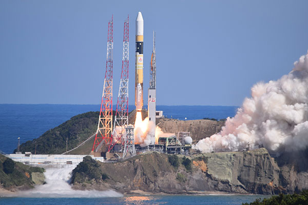
At 02:19:37 UTC on Oct. 26, 2021, a new satellite in the QZSS constellation — QZS-1R — was launched from the Tanegashima Space Center in Japan. It is the fifth satellite in the constellation and the replacement of the first satellite, launched in September 2010.
As of December 2021, initial on-orbit testing (IOT) and tuning of the precise orbit determination (POD) function in the ground control segment was ongoing. QZS-1R is the first QZSS satellite that will transmit the L1 C/B signal, splitting the power spectrum at the L1 center frequency by adopting BOC modulation on the existing C/A signal, to mitigate interference into the GPS L1 C/A signal. C/B signal transmission was verified during the IOT phase. QZS-1R will transmit the C/A signal continuously until QZS-5, 6 and 7 are launched and the noise floor increased.
The launch of QZS-1R was a milestone toward a sustainable national infrastructure for Japan. The Japanese government’s Cabinet Office (CAO) is trying to establish more secure positioning, navigation and timing (PNT) services by deploying seven satellites for the QZSS constellation. It will add three satellites to the current four around 2023.
This will give QZSS an independent PNT capability and enhance GNSS performance as well as robustness, and cover a broader area in the Asia Pacific region. CAO is still investigating the future of the QZSS constellation, including its final configuration and how to provide assured PNT services corresponding to future user requirements. However, it is thought that the full operational capability for Japan at minimum may be declared after the completion of the initial seven-satellite constellation.
Today, QZSS is providing ranging signals on L1C/A, L1C, L2C and L5 for all users able to acquire and track those signals. Those signals have the same RF properties and almost the same message format as the corresponding GPS signals — they are interoperable.
In addition, a unique characteristic of QZSS is that it transmits error correction messages available in Japan on separate channels — L1S, L1Sb and L6 — from those used to broadcast its ranging signals. Messaging functions are also provided through QZSS L1S and S-band two-way communication links on QZS-3 in support of disaster mitigation and relief operations in Japan.
CAO launched the QZSS operational services using a four-satellite constellation on Nov. 1, 2018. Its first three years of operation have provided much knowledge to improve their performance. The averaged signal-in-space user ranging error, a 95 percentile daily statistic, has been improved and achieved less than 1.0 meter, while the specification is 2.6 meters; the best daily value in the evaluation period (Aug. 31, 2020 to Sept. 1, 2021) was less than 0.5 meter for QZS-1, 2 and 3.
This remarkable improvement was shown on the Centimeter Level Augmentation Service (CLAS). According to the original design of CLAS, transmitted error corrections were for only 11 satellites in the GPS, QZSS and Galileo constellations. After two years of initial operation, we updated the ground control segment for CLAS to increase the number of augmented satellites from 11 to a maximum of 17. This increase in the number of satellites with error corrections leads to excellent improvement of CLAS performance in more challenging user environments such as urban and mountainous areas.
To improve the service performance further and measure new observables for satellite orbit clock estimation, inter-satellite ranging and two-way ranging functions between tracking station and satellite will be developed for QZS-5 to -7 and following satellites. The ground control segment will also be updated.
Multi-GNSS ADvanced Orbit and Clock Augmentation (MADOCA) precise point positioning (PPP) will be implemented as a practical service no later than 2024. It is aiming to provide decimeter-level PPP service with broadcast of globally available satellite orbit and clock error corrections as well as code-phase and carrier-phase biases.
PPP has a well-known disadvantage: long convergence time. By using the marginal L6D channel on QZS-5 to -7, the ionospheric delay correction for wide area will be distributed. CAO will try to evaluate how such ionospheric correction could reduce the initial convergence time for the PPP calculation. In an experiment planned in collaboration with Asian Pacific countries, regional stations in the nationwide CORS network will be used for generating such corrections.
Early or Emergency Warning Service (EWS) is also expanding its service coverage into the region. The common EWS format is being jointly investigated by India, the European Union and Japan under the UN-ICG framework. The QZSS EWS for the Asia Pacific region through the L1S signal on QZS-1R, 2, 3 and 4 will be established after completion of a ground segment update around 2024.
This month we bring you a guest column by Steffen Thoelert, André Hauschild, Peter Steigenberger and Oliver Montenbruck of the German Aerospace Center (DLR) and Richard B. Langley of the University of New Brunswick.
UPDATE:Since Sept. 10, continuously operating DLR receivers in Sydney, Australia, and Chofu, Japan, have been reporting measurements from QZSS satellite J07, which, according to the QZSS Interface Control Document, is the geostationary satellite QZS-3.
The second satellite of Japan’s Quasi-Zenith Satellite System (QZSS) has started transmitting navigation signals. QZS-2, or Michibiki-2, was launched on June 1, 2017, and joins its predecessor QZS-1 (Michibiki-1), which has been in orbit since September 2010.
Both satellites have been placed into inclined geosynchronous, elliptical orbits, which enable extended satellite visibility periods over Japan and are characteristic features for this regional navigation system.
The third satellite, QZS-3, was launched on Aug. 19, 2017, into a geostationary orbit. If all goes according to plan, a fourth satellite in an eccentric orbit will follow by the end of this year and complete the constellation.
QZS-2 Signal Tracking
It is not straightforward to tell when QZS-2 started signal transmission exactly. About four weeks after launch, on June 27 between 10:17 and 12:37 UTC, several Septentrio PolaRx GNSS receivers in the Asia-Pacific region recorded continuous L5 observations. About one week later, on July 4 shortly after 03:02 UTC, Javad and Trimble receivers picked up L1 C/A and L5 signals from QZS-2 for a few seconds. Then again, between 23:03 UTC on July 6, and 01:36 UTC on July 7, several receivers intermittently tracked the L1 C/A, L2C and L5 signals. Finally, on July 10, starting at approximately 01:03 UTC, these three signals were continuously tracked until approximately 04:00 UTC on July 12. Up until Aug. 1, signal tracking had remained intermittent, but has been stable since. This was presumably the result of interruptions in the signal transmission due to test activities.
Figure 1. QZS-2 signals tracked by GNSS receivers in Chofu, Japan, (top plot) and Sydney, Australia, (bottom plot). The plots depict the measured C/N0 for L1 C/A (black), L2C (red) and L5 (green) together with the observed pseudorange (grey). The frequent discontinuities in the pseudorange are due to the receiver clock adjustments. Both receivers exhibited a short tracking outage at approximately 06:00 UTC. The interruption in tracking at Chofu around 08:00 UTC is due to the low elevation angle of the satellite.
The plots in FIGURE 1 show QZS-2 signals as tracked by GNSS receivers in Japan and Australia on July 10. The two first sets of broadcast messages were transmitted on July 16 at 6:00 and 7:00 UTC. Regular transmission of broadcast ephemerides started on July 27 at 22:00 UTC, but deviations from the hourly update rate still occur from time to time.
Identical or Fraternal Twins?
At first glance, QZS-2 seems like a look-alike of QZS-1, but there are many differences between the two spacecraft. Most apparent is the presence of an additional auxiliary antenna. Like QZS-1, QZS-2 transmits its navigation signals on the L1, L2, L5 and L-band Experiment (LEX) frequencies through the main antenna, while the augmentation signal L1S (formally known as Submeter-class Augmentation with Integrity Function or SAIF) is transmitted from a separate antenna. However, the new L5S signal, which is introduced with QZS-2, is transmitted with yet another antenna.
The new satellite also has a shorter “wingspan” of only 19 meters, since it is equipped with two solar panel segments on each side, compared to three segments for QZS-1 with a width of 25.3 meters. The second QZSS satellite also follows a different attitude model: Unlike QZS-1, which switches between yaw-steering mode and orbit-normal mode depending on the sun’s elevation angle with respect to the orbit plane, QZS-2 always remains yaw-steering except for short periods of time when orbit maneuvers are performed. Further differences will become apparent in the analysis of the signal spectra in the subsequent sections.
The Cabinet Office of the Government of Japan, which oversees QZSS as a national undertaking, has published QZSS satellite metadata information on its official website. At the time of writing, only one document for QZS-2 is available, which contains information about the satellite’s properties such as mass, dimension, attitude law and reference frame, but also antenna and laser retroreflector positions, antenna phase-center offsets and variations as well as signal group delays.
Additional documents containing metadata for QZS-1, -3 and -4 and further information about QZS-2 are in preparation.
Rubidium Clock
FIGURE 2 illustrates the stability of the QZS-2 rubidium atomic frequency standard (RAFS) by means of the Allan deviation (ADEV). Data from a global network of 150 GNSS stations was processed to estimate GPS and QZSS satellite orbit and clock parameters.
Figure 2. Allan deviation of the rubidium atomic frequency standards of GPS Block IIF satellite G32, QZS-1 (J01) and QZS-2 (J02).
However, whereas about 60 of these stations provide QZS-1 observations, QZS-2 is only tracked by 13 stations. ADEV values for QZS-1, QZS-2 and a GPS Block IIF satellite were computed from a daily solution for Aug. 3 with 30-second clock sampling.
At an integration time of 100 seconds, the QZS RAFS reaches an ADEV of better than 3 × 10-13.
At longer integration times, the QZS-2 clock almost reaches the stability of the GPS Block IIF RAFS.
Based on this preliminary analysis for only one day, the QZS-2 clock seems to perform as expected. The larger ADEV values compared to QZS-1 for integration times up to 1,000 seconds might be attributed to the significantly smaller number of tracking stations contributing to the QZS-2 clock solution. The quality of the clock solution will improve as soon as more stations are able to track QZS-2.
Signals with High-Gain Antenna
Complementary to the receiver measurements and analysis, the German Aerospace Center (DLR) has also recorded raw spectral and in-phase and quadrature (IQ) data of QZS-2 to get further insights into the transmitted signal structure and initial signal quality. FIGURE 3 shows a spectral measurement of the complete GNSS L-band frequency range, which shows the signal transmissions of QZS-2 in the L1, L2, L5 and L6 bands. The signal was captured with DLR’s 30-meter high-gain antenna at Weilheim, southwest of Munich, operated by DLR’s German Space Operations Center.
Figure 3. QSZ-2 L-band normalized power spectra recorded at Weilheim, Germany, on July 18, 2017 at 20:43 UTC.
This first view of the signal transmission shows a good spectral shape, appropriate band filtering and no out-of-band unwanted spurious emissions of the satellite. For further analysis, we looked closer at each signal-band spectrum and performed IQ-sample recording.
Comparing the QZS-2 spectra to that of QZS-1, we see differences in the signal structure for the L1 frequency band.
Figure 4. QZS-1 and QZS-2 L1 spectral flux density.
FIGURE 4 shows the L1 spectra of both satellites. The additional signal component can be seen at an offset of 6 x 1.023 MHz and 18 x 1.023 MHz from the L1 center frequency of 1575.42 MHz. This is the result of the new L1C-pilot modulation, which is based on the time-multiplexed binary offset carrier (TMBOC) modulation technique using a mixture of BOC(1,1) and BOC(6,1). See here for detailed information.
Another difference is present in the L6 band and can be seen within the signal time domain or the IQ domain. The new satellite transmits two components (one each for the I- and Q-channels) while QZS-1 transmits only one I-component. This observation is fully in line with the QZSS Interface Specification. On QSZ-2, an additional L6 signal component (Centimeter-Level Augmentation Message for Experiments, L6E) is implemented. FIGURE 5 shows the IQ constellation plots of QZS-1 and QZS-2 for the L6 band.
Figure 5. L6 IQ constellation plots for QZS-1 (left) and QZS-1(right).
Source: GPS World
Furthermore, the L5 band IQ plot of QZS-2 exhibits significant differences compared to QZS-1. These differences, which are illustrated in the plots of FIGURE 6, are due to an additional L5S signal transmitted by QZS-2.
Figure 6. L5 IQ constellation plots for QZS-1 (left) and QS-2 (right).
Source: GPS World
The QZS-2 L5 IQ diagram is fairly easy to understand as a coherent superposition of two distinct quadrature signals from two antennas. One signal is the GPS-like L5 signal transmitted from the main L-band antenna, while the other (L5S) signal originates from a new L5S antenna. This is illustrated in FIGURE 7.
Figure 7. QZS-2 L5 IQ constellation plot including demarcation of the L5 and L5S signals.
For illustration purposes, the dashed orange square in Figure 7 relates to the 10 MHz L5 signal, while the smaller red squares are the 10 MHz L5S signal.
A code generator has been setup according the QZSS L5 and L5S interface control document (ICD). An analysis of the correlations of possible pseudorandom noise (PRN) codes resulted in the detection of PRN 194 and PRN 196. Based on the information in the ICDs, PRN 194 is used for L5 and PRN 196 is used for L5S.
The performed code correlation analysis also yields the finding that the L5 signal is approximately 3.5 dB stronger than the L5S signal. Note, however, that both signals have a specified minimum receive power of -157 dBW. Due to the limited visibility of QZSS satellites from the Weilheim ground station, it is not possible to verify this value.
Conclusion
With the launch and activation of QZS–2, the deployment of Japan’s regional navigation system is moving forward again. The launch of a geostationary satellite, QZS-3, took place on Aug. 18. A fourth Japanese navigation satellite is scheduled to launch later this year. With this rapid sequence, the target date of 2018 for the completion of an operational constellation with four satellites is quite realistic.
Steffen Thoelert, André Hauschild, Peter Steigenberger and Oliver Montenbruck are from the German Aerospace Center (DLR).
Richard B. Langley is from the University of New Brunswick and authors the monthly Innovation column for GPS World magazine.
The Japan Aerospace Exploration Agency (JAXA) has controlled the orbit of the first quasi-zenith satellite system (QZSS) satellite, Michibiki. JAXA inserted Michibiki into the quasi-zenith orbit from the drift orbit starting on Sept. 21. The final orbit control operation was performed for about 50 seconds from 6:28 a.m. on Sept. 27 JST (Japan Standard Time).
After the operation, JAXA confirmed that the satellite was successfully injected into its preordained quasi-zenith orbit with its center longitude of about 135 degrees through the orbit calculation. The calculation results are as follows.
Michibiki was launched from the Tanegashima Space Center at 8:17 p.m. JST on Sept. 11.
JAXA will carry out the initial functional verification of the onboard mission devices in cooperation with organizations that will perform technological verifications for about three months. These organizations include the Geospatial Information Authority of Japan, the National Institute of Advanced Industrial Science and Technology, the National Institute of Information and Communications Technology, the Electronic Navigation Research Institute, and the Satellite Positioning Research and Application Center.
JAXA provided these definitions of drift and quasi-zenith orbit:
Drift orbit: The last step orbit prior to the quasi-zenith orbit. The orbit altitude and inclination (angle against the equator) are equal to those of the quasi-zenith orbit, but the longitude of the center of the figure-8 orbit is not above Japan. After being injected into the drift orbit, it will take a few days to maneuver the satellite to have its figure-8 center above Japan, thus it will ultimately fly in the quasi-zenith orbit.
Quasi-zenith orbit: While the quasi-zenith orbit has the same orbit period of 23 hours and 56 minutes as the geostationary orbit, it can let a satellite stay over Japan longer by taking an elliptical orbit with higher altitude above Japan and flying in a figure-8 orbit.