Collaboration supports emergency services across the European Union
Galileo-supported E112 will result in faster response times and more lives saved. (Image: EUSPA)
Keysight Technologies Inc. is collaborating with DEKRA to ensure that chipset and device vendors can validate E112 caller location (universal European emergency number) functionality in compliance to a new European Union (EU) regulation.
The collaboration leverages GNSS and c (LBS) to verify E112 regulatory test cases used to validate mobile phones sold into the European market. The new regulation supports emergency services across the European Union by reducing response times from rescue services to save more lives.
“Keysight is pleased to expand the company’s collaboration with DEKRA,” said Muthu Kumaran, general manager of Keysight’s Device Validation Solutions business. “With Keysight’s test solutions, DEKRA supports a global ecosystem of smartphone vendors by validating that their products are in compliance to the new regulation, newly created to improve emergency services’ ability to locate individuals in need of assistance from the fire brigade, medical teams or the police.”
Keysight’s network emulation solutions enable DEKRA to validate E112-related test cases regulated by an EU-issued guideline document to assist notified bodies in the assessment of E112 compliance. The new EU regulation (Delegated Regulation (EU) 2019/320) went into effect on March 17, 2022. It mandates that all new mobile phones sold in the EU need to support GNSS technology based on the Galileo constellation, advanced mobile location (AML) protocol and Wi-Fi communications technology. As a result, emergency response call centers can accurately pinpoint the caller’s location.
“DEKRA is founded on the principles of safeguarding human interaction with technology and environment,” said Juan Carlos Mora, vice president, Business Line Connectivity of Service Division, Product Testing at DEKRA. “This is why we are pleased to extend our collaboration with Keysight, which offers DEKRA the regulatory device test solutions needed to quickly and confidently validate E112 caller location functionality per the EU’s latest mandatory requirements.”
Keysight’s device test solutions for regulatory and conformance validation are based on common hardware and software platforms for comprehensive test-case coverage. Keysight’s LBS solutions also support assisted GNSS (A-GNSS) test functionality. This enables users to comprehensively address 5G new radio (NR) conformance requirements mandated by the Global Certification Forum (GCF) and PTCRB, an organization comprised of North American mobile operators.
Integrated solutions address GNSS test requirements defined by 3GPP and major U.S. carriers
Orolia and Keysight Technologies Inc. have joined forces to advance 5G services by addressing GNSS test requirements defined by 3GPP and major U.S. carriers.
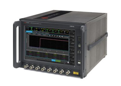
Working with Orolia allows Keysight to extend its 5G device test solution portfolio with advanced GNSS simulation capabilities. As a result, existing users of Keysight’s 5G device test solutions can easily address GNSS-related 3GPP protocol conformance and carrier acceptance test requirements by upgrading the software in Keysight’s E7515B UXM 5G Wireless Test Platform and combining it with Orolia’s GSG-8 simulator.
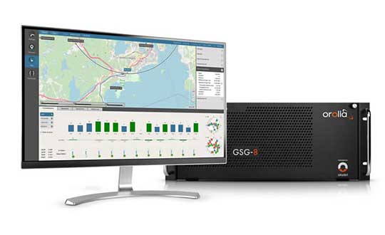
Skydel GSG-8 (Photo: Orolia)
The efforts of Keysight and Orolia will enable chipset and device makers to verify functionality to accurately position mobile phone users within a geographic area.
“Working with Orolia has enabled Keysight to deliver GNSS-based LBS test solutions for 5G protocol conformance and carrier acceptance validation,” said Muthu Kumaran, general manager of Keysight’s device validation solutions business. “Keysight’s LBS solutions also support assisted GNSS test functionality, enabling users to comprehensively address 5G new radio conformance requirements mandated by both the Global Certification Forum (GCF) and PTCRB.”
Accurate positioning is important in a wide range of sectors including healthcare, road and aerial transportation, entertainment and homeland security.
Future applications, such as drones and autonomous vehicles, will depend on highly precise positioning services for reliable navigation and safe transportation of people and goods. Mobile operators use GNSS technologies and non-GNSS technologies, such as beamforming, angle-based positioning and round-trip time to deliver personalized services and support emergency calls.
Keysight’s UXM 5G Wireless Test Platform. (Photo: Keysight Technologies)
The GSG-8 simulator, powered by the Skydel Simulation Engine, offers high performance, flexibility and an easy-to-use software-defined platform to deliver superior jamming and spoofing options that can help ensure accurate, continuous operations for critical applications during interference or signal loss. Automated and scalable, the simulator supports GPS, Galileo GLONASS and BeiDou, with upgrade paths for future constellations.
Keysight offers in-built positioning capabilities in the UXM 5G wireless test platform for non-GNSS positioning test requirements.
“We are pleased to collaborate with Keysight on developing solutions that improve PNT testing for 5G communication networks and devices,” said Lisa Perdue, Orolia’s Simulation Product Line director. “Our GSG-8 simulator, powered by Orolia’s Skydel Simulation Engine, offers ultra-high performance and unmatched flexibility. The easy-to-use software-defined platform also delivers superior jamming and spoofing options that can help ensure accurate, continuous operations for critical applications during interference or signal loss.”
When a Pennsylvania county’s 911 system suddenly went down without warning, garbled messages across the network impacted fire and police agencies’ ability to respond to emergency messages. The issue was traced to a firmware malfunction on communications equipment, related to provision of GPS timing. The firmware had not been updated for 19-1/2 years. Why should it have been? Everything was working fine — until it didn’t.
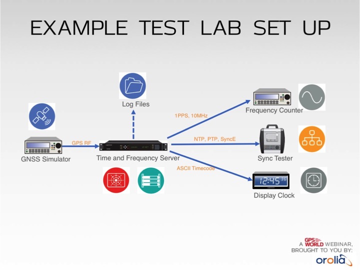
Test lab set-up. Photo: Orolia
In addition to increased jamming and spoofing threats, GPS has a “week rollover event” set to happen in April 2019. If the GPS receivers found at the heart of many critical systems do not handle this properly, any number of failures can occur.
Without GPS timing, everything slows down, has less capacity and becomes more dangerous.
This Thursday, a complimentary webinar outlines test plans for GNSS equipment used in critical timing applications, discusses the need for assured access to accurate timing across financial institutions, industrial automation, telecommunications, transportation, the power grid and elsewhere — and defines just what “assured” access means and how crucial the “assured” part is — and finally reviews some recent mishaps and near-disasters caused by interrupted or inaccurate timing.
Speaking on the 1-hour webinar are Lisa Perdue, product manager and applications engineer, Orolia; Stefania Römisch, leader, the Atomic Standards Group at the National Institute of Standards and Technology; and Dana Goward, president, Resilient Navigation and Timing Foundation.
Following each speaker’s 12- to 15-minute slide presentation, a live Q&A period with the audience will explore particular issues and concerns.
In mid-2017, Talen-X and Skydel engineers began to conceptualize a GNSS simulation system emanating from their BroadSim platform for the purpose of fortifying anechoic chambers.
Over the next six months, Talen-X and Skydel designed, built, tested and delivered an anechoic chamber simulator capable of simultaneously generating multi-GNSS jamming and spoofing signals.
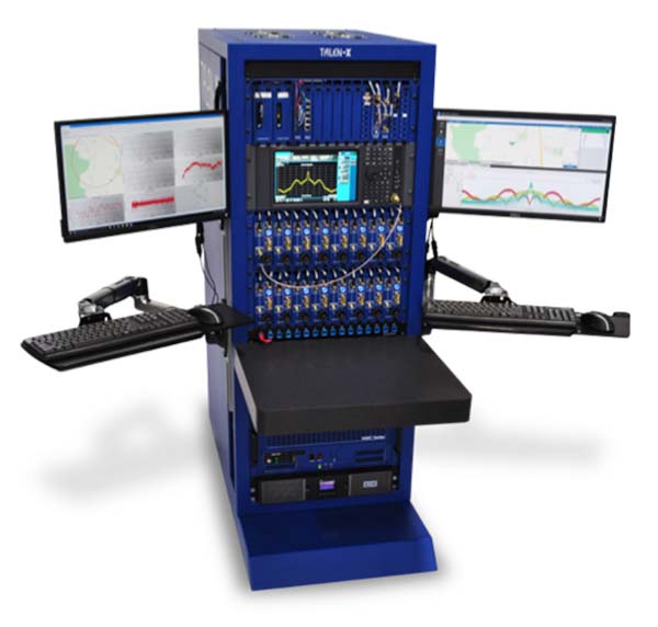
BroadSim Anechoic can be used to support a wide variety of operational tests.
“Our new Anechoic Chamber solution will radically change the way in which mission critical platforms and systems are tested because we are enabling our customers to create real-world threats,” said Talen-X Chief Technology Officer Tim Erbes said. “Not only will BroadSim Anechoic be able to emulate real-world threat scenarios, it will be easier than ever before to create and simulate these environments.”
BroadSim Anechoic is used to test GNSS spoofing and jamming in an anechoic chamber. The BroadSim Controller is at the heart of the system running Skydel’s SDX software suite. Using SDX, users can create advanced scenarios that include both jamming and spoofing signals.
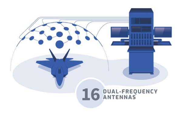
The 16 software-defined radios (SDRs) each with dual transmit ports (32 total outputs) can be configured to output GNSS or jamming signals, giving users flexibility to run test after test. The transmit chains include the hardware to power 16 dual-frequency antennas. The included GNSS receivers allow users to monitor the environment inside the chamber, providing confidence that tests are running correctly.
The BroadSim Anechoic can also be used in controlled radiation pattern antenna (CRPA) testing. Many ground-, airborne- and water-based platforms are transitioning to using CRPAs because of their added jamming resiliency and significant tracking advantages in degraded environments.
Validation and real-world testing is critical to understanding and characterizing the mitigation these antennas can add in highly degraded areas. By using BroadSim Anechoic, users have the ability to create representative jammers with real-world characteristics (modulations, frequencies, angles, power levels, etc).
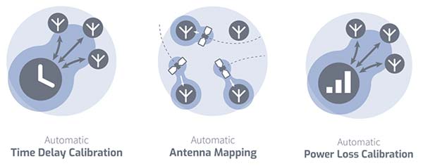
“Skydel developed an innovative approach for time offset calibration between multiple transmitting antenna using a COTS Software-Defined Radio (SDR),” said Skydel Solutions Chief Technology Officer, Iurie Ilie. “This approach allows for very precise measurements and adjustments (better than 100ps) to be done automatically before simulation start. At the same time, transmitting signal power is automatically adjusted to keep the power offset at receiving antenna better than 0.1dB.”
BroadSim Anechoic takes advantage of state-of-the-art software defined radios (SDR) for RF up-converting while signal IQ generation is done using high performance commercial-off-the-shelf (COTS) graphics-processing units (GPU). The ability to generate the IQ data in software (using the GPU) as opposed to hardware (FPGA) significantly reduces the cost while maximizing capability, value, and time to market.
BroadSim Anechoic has the capability of powering up to 16-dual frequency antennas requiring 32 RF transmit outputs. The architecture used for this system required the ability to receive signals in a manner such that precise processing could be done on the receive signal.
The SDR selected for this application has one receiver channel for every transmit channel giving BroadSim Anechoic 32 RF receive ports. Innovative software techniques have been developed enabling the accurate time and power calibration for each antenna transmit chain using the SDR receive ports.
Modules featuring Altair’s ALT1250 CAT-M1/NB1 chipset will be demonstrated at Mobile World Congress.
Altair Semiconductor, a provider of LTE chipsets, has selected Rohde & Schwarz as its partner for test equipment for its dual-mode CAT-M1/NB1 internet of things (IoT) ALT1250 chipset, as well as its next-generation IoT chipsets.
The ALT1250 is a highly integrated dual-mode CAT-M1/NB-IoT chipset with GNSS. Modules with ALT1250 inside are the world’s smallest, and may be as small as 100 millimeters square in area.
The ALT1250 includes GNSS location positioning, a wideband RF front-end supporting all commercial LTE bands within a single hardware design, a multi-layered and hardware-based security framework, an internal application subsystem and packaging that enables standard, low-cost PCB manufacturing.
The Rohde & Schwarz R&S CMW500 test platform offers the most validated CAT-M1/NB-IoT protocol conformance tests. It allows manufacturers and test houses to use a single instrument to verify that chipsets, modules and devices comply with GCF and PTCRB standards, and specific network operator requirements.
The test equipment will be used for protocol testing as well as RF, RRM performance and carrier tests.
Rohde & Schwarz is a global manufacturer of wireless communications and EMC test and measurement equipment and plans to develop new testing protocols for Altair’s next generations of cellular IoT chipsets.
“Our ALT1250 chipset is already forming the foundation for multiple current and emerging IoT applications,” said Ilan Reingold, VP of business development and marketing for Altair. “The choice of Rohde & Schwarz is part of our commitment to the highest quality of advanced validation and performance testing for our game-changing products.”
“This announcement confirms the commitment of Rohde & Schwarz to the wireless industry to provide innovative test tools and solutions that allow the testing and certification of cellular IoT devices,” said Anton Messmer, vice president, mobile radio testers, for Rohde & Schwarz. “We are pleased to have been selected by Altair and are looking forward to supporting them in the development of highly integrated chipsets in conformance with 3GPP Release-13 standards for CAT-M1 and NB-IoT, and beyond.”
Altair will be demonstrating partner modules based on ALT1250 at Mobile World Congress (MWC) in Barcelona, Spain, Feb. 26 to March 1 at Altair meeting rooms in Hall 2, Stands 2B2Ex and 2B4Ex.
Rohde & Schwarz will showcase CAT-M1/NB-IoT test solutions with the R&S CMW500 at MWC in hall 6, booth 6C40.
Working with the Radio Technical Committee for Maritime Services (RTCM), Spirent has created test scenarios that simulate realistic satellite reception conditions at sea so that GPS distress beacon performance can be improved, allowing users to be rescued faster by search and rescue organizations.
One of the first customers to use these scenarios to test its locator beacons is ACR Electronics Inc., a manufacturer of emergency lifesaving equipment. Its latest ACR and ARTEX products have been tested using a Spirent signal simulator, and have been certified as meeting the RTCM standards for cold-start time-to-first-fix, which specifies the time taken by a device when it is turned on to capture GPS signals and determine its location.
Photo: Spirent
The U.S. Federal Communications Commission (FCC) has now mandated that in future, any new products in the related categories must be tested using a GNSS simulator and the scenarios in the RTCM standards, which were developed by Spirent.
“We are able to test the performance of our dual-frequency GPS/Galileo receivers using a Spirent simulator that can accurately simulate signals from different constellations to enhance the performance of our Emergency Position Indicating Radio beacons (EPIRBs, PLBs and ELTs),” said Bill Cox, Director of Engineering at ACR. “Our customers will soon be able to take advantage of a new confirmation system that will let them know that their call for help was heard.”
“We are very pleased to have worked with RTCM and ACR to improve maritime safety”, said Martin Foulger, General Manager of Spirent’s Positioning Business Unit. “This project shows the importance of testing in realistic conditions to give better end-user experience, which in this case could be a matter of life or death. This will make lifesaving equipment more reliable both for maritime users and search and rescue agencies.”
Photo: Spirent
The RCTM discovered that Cospas-Sarsat 406MHz beacons with integral GPS receivers suffered from poor cold start performance, causing delays in providing accurate location information to Search and Rescue (SAR) authorities. It later discovered that this was because beacons tended to be tested on land in benign conditions, rather than in real-world oceanic conditions.
It has addressed the issue by specifying a set of performance standards for Emergency Position Indicating Beacons (EPIRBs), Personal Locator Beacons (PLBs), Hand-held VHF Radios with integral GPS Receivers, Manoverboard (MOB) devices and Satellite Emergency Notification Devices (SENDs).
Spirent was asked to develop a set of custom test scenarios that enable manufacturers to simulate realistic satellite reception conditions at sea in laboratory environments. Use of these scenarios enables manufacturers to better assess the performance of their products in the real world.
Details of the FCC mandate can be found in the Federal Register, Vol. 81, No. 241, Dec. 15, 2016, Page 90739, FCC 47 CFR Parts 1, 25, 80 and 95.
Spirent Communications is now offering the Elevate IoT Device Test Solution, a new cellular test solution designed to support a wide range of testing areas applicable to Internet of Things (IoT) applications, including end-to-end cloud server connectivity, security vulnerability assessment and battery-life measurement.
The announcement was made at Mobile World Congress, which is taking place Feb. 27 to March 2 in Barcelona, Spain.
The compact and flexible device test solution, available via the Spirent Elevate platform, addresses critical areas that are affected when designing 3G, LTE, and upcoming narrowband wireless technologies into IoT devices.
Innovative IoT developers are emerging worldwide with many of their applications reliant on communicating via a cellular network. Cellular deployment has several benefits including higher guaranteed service quality, more robust air interface security, and broader coverage availability. Yet designing IoT devices can present a myriad of complex challenges, especially when cellular connectivity enters the equation.
Testing on a live network has several limitations: data traffic is not visible between the device and cloud server; the appropriate live network may not be deployed where the development takes place; and there is no ability to control network settings such as power levels.
Spirent Elevate provides easy access to a controllable, lab-based testing environment, allowing developers to explore the special challenges a cellular network presents in a repeatable manner.
A number of recent events, including widespread Distributed Denial of Service (DDoS) attacks, has illustrated the very real exposure of IoT device security, highlighting the immediate need for developers to ensure devices are protected from known baseline vulnerabilities.
The Elevate IoT test solution facilitates access to Spirent SecurityLabs services, including dedicated teams of experienced security professionals offering comprehensive scanning, penetration testing and monitoring services for embedded devices.
Many IoT devices require operation in hard-to-reach places for extremely long periods of time while in potentially unforgiving environments, making it imperative that batteries perform as expected under variable conditions. The Elevate IoT Device Test Solution allows developers to accurately determine predictable battery life in real-world conditions with actual usage profiles.
“The Internet of Things is here to stay — it represents a cultural and technology revolution, and has serious implications for security,” said Jeff Wilson, research director and advisor, cybersecurity technology, at analyst firm IHS. “The post-IoT threat landscape is complicated, and the consequences of attacks are increasingly severe. If a device is compromised, it can either fail to work itself, or introduce threats into a wider network, or both; the Mirai and LizardStresser IoT botnets used to launch DDoS attacks were just the tip of an enormous iceberg. Successfully managing connectivity, technology and risk will be vital to IoT implementations from this point forward.”
Spirent’s IoT Device Test Solution is an integrated suite of tools centered in a compact network emulator that brings a repeatable cellular test bed into any hardware or software lab, providing the ability to replicate service providers’ wireless networks in a portable desktop system.
When used as part of an expanded Spirent solution that can simulate multiple types and levels of security attacks, the system allows users to accurately understand how a device will hold up against each one and what factors may be impacted.
Emulating as many conditions as possible helps developers understand exactly how devices, including factors such as battery life, may be impacted in the real world.
“For IoT developers, many of them new to cellular technology, it can be dauntingly complex to navigate new technologies, manage power performance challenges, and care for imminent cybersecurity threats,” said Saul Einbinder, vice president of new venture development at Spirent Communications. “Our aspiration is to help developers, operators, and service providers optimize their IoT solutions and get to market faster, while also staying considerate of the budget constraints of IoT device realization.”
New cars for the Russian market must be equipped with the automatic ERA-GLONASS emergency call system.
For certification of these in-vehicle systems, both conformance and performance tests are mandatory, in line with the Russian GOST R 55534 specification.
The Rohde & Schwarz CMW500 is being used to test the ERA-GLONASS system.
For both types of tests, the Russian Certification Center Svyaz-Certificate uses standard-compliant test solutions from Rohde & Schwarz. Manufacturers and component suppliers can use the same test solution in pre-tests to speed up certification for their products.
Now, for the newly required performance test, the center is using the GNSS simulator in the R&S SMBV100A vector signal generator.
Accuracy Requirements. During performance testing, it is verified whether the GNSS receiver of an ERA-GLONASS emergency call system fulfills the accuracy requirements of the specification.
In case of an emergency, the call system should not only correctly transmit position data according to a specified protocol to the public safety answering point, but position data must also be accurate so that the first responder can locate the accident vehicle quickly.
ERA-GLONASS module manufacturers and test houses can use the R&S SMBV100A during pre-tests to create reliable and reproducible conditions similar to those in official certification tests, according to Rohde & Schwarz, to minimize the risk of failing tests during certification.
A: Current integrations of GPS include a controlled reception pattern antenna (CRPA). Testing with a standard interference or jamming source will not provide accurate results. Wavefront generator simulators are capable of outputting signals that correctly stimulate the GPS receiver’s antenna electronics. All of the signals are correctly displaced according to the antenna’s reception pattern with a jamming source that is coherent.
A: Testing GNSS receiver spoofing and jamming resilience under real-life scenarios requires mixing live-sky GNSS signals with synthesized spoofed signals. This requires the spoofing signal generator to be time- and position-locked to the live-sky signal to within nanoseconds. GNSS simulators that allow nanosecond-level synchronization to live-sky signals can enable such testing. Low-cost simulators can enable testing with multiple simultaneous spoofers/jammers.
A: With the sophistication of GNSS threats, simulators should be able to generate a variety of interferences and jammers that users can easily control. Also, the jammers’ characteristics (Doppler, power level, and so on) should reflect the dynamic of the vehicle and jammers. Such characteristics are almost impossible to simulate when the jamming source is not integrated with the simulator.
A: For jamming, test for multi-frequency/constellation, accurately controlling jamming-to-signal ratios and strength levels, and simulate several types of jammers: carrier-wave, sweep, noise, FM chirp and so on. For spoofing, two synchronized simulators are best: one for the live sky and one for the spoofer. Tightly control the sync accuracy, the relative power between the two signals, and the spoofer’s estimation accuracy of the target’s position.
A: Antenna technology, directionality and filtering have a large part to play in mitigating the impact of jamming and spoofing. Conventional laboratory receiver testing often overlooks the effect of the antenna. New approaches need to be developed to allow antenna effects be incorporated into testing either by including the antenna to be part of the test setup or by accurately simulating the directionality/filtering capability of the antenna.
A: Most jamming occurs due to RFI used to keep positioning unavailable. As such, typical jammers are CW or sweep-CW. Testing is then mostly a matter of proper jamming-to-signal simulation. On the contrary, spoofing aims at luring the receiver from its true position. Simulations are difficult as slowly power increasing spoofing signals must be synchronized with true received signals to take over the locked tracking loops.
Tests of the robustness of commercial GNSS devices against threats show that different receivers behave differently in the presence of the same threat vectors. A risk-assessment framework for PNT systems can gauge real-world threat vectors, then the most appropriate and cost-effective mitigation can be selected.
Vulnerabilities of GNSS positioning, navigation and timing are a consequence of the signals’ very low received power. These vulnerabilities include RF interference, atmospheric effects, jamming and spoofing. All cases should be tested for all GNSS equipment, not solely those whose applications or cargoes might draw criminal or terrorist attention, because jamming or spoofing directed at another target can still affect any receiver in the vicinity.
GNSS Jamming. Potential severe disruptions can be encountered by critical infrastructure in many scenarios, highlighting the need to understand the behavior of multiple systems that rely on positioning, and/or timing aspects of GNSS systems, when subject to real-world GNSS threat vectors.
GNSS Spoofing. This can no longer be regarded as difficult to conduct or requiring a high degree of expertise and GNSS knowledge. In 2015, two engineers with no expertise in GNSS found it easy to construct a low-cost signal emulator using commercial off-the-shelf software–defined radio and RF transmission equipment, successfully spoofing a car’s built-in GPS receiver, two well-known brands of smartphone and a drone so that it would fly in a restricted area.
In December 2015 the Department of Homeland Security revealed that drug traffickers have been attempting to spoof (as well as jam) border drones. This demonstrates that GNSS spoofing is now accessible enough that it should begin to be considered seriously as a valid attack vector in any GNSS vulnerability risk assessment.
More recently, the release of the Pokémon Go game triggered a rapid development of spoofing techniques. This has led to spoofing at the application layer: jailbreaking the smartphone and installing an application designed to feed faked location information to other applications. It has also led to the use of spoofers at the RF level (record and playback or “meaconing”) and even the use of a programmed SDR to generate replica GPS signals — and all of this was accomplished in a matter of weeks.
GNSS Segment Errors. Whilst not common, GNSS segment errors can create severe problems for users. Events affecting GLONASS during April 2014 are well known: corrupted ephemeris information was uploaded to the satellite vehicles and caused problems to many worldwide GLONASS users for almost 12 hours. Recently GPS was affected. On January 26, 2016, a glitch in the GPS ground software led to the wrong UTC correction value being broadcast. This bug started to cause problems when satellite SVN23 was withdrawn from service. A number of GPS satellites, while declaring themselves “healthy,” broadcast a wrong UTC correction parameter.
Atmospheric Effects. Single frequency PNT systems generally compensate for the normal behavior of the ionosphere through the implementation of a model such as the Klobuchar Ionospheric Model.
Space weather disturbs the ionosphere to an extent where the model no longer works and large pseudorange errors, which can affect position and timing, are generated. This typically happens when a severe solar storm causes the Total Electron Count (TEC) to increase to significantly higher than normal levels.
Dual-frequency GNSS receivers can provide much higher levels of mitigation against solar weather effects. However, this is not always the case; during scintillation events dual frequency diversity is more likely to only partially mitigate the effects of scintillation.
Solar weather events occur on an 11-year cycle; the sun has just peaked at solar maximum, so we will find solar activity decreasing to a minimum during the next 5 years of the cycle. However that does not mean that the effects of solar weather on PNT systems should be ignored for the next few years where safety or critical infrastructure systems are involved.
TEST FRAMEWORK
Characterization of receiver performance, to specific segments within the real world, can save either development time and cost or prevent poor performance in real deployments. Figure 1 shows the concept of a robust PNT test framework that uses real-world threat vectors to test GNSS-dependent systems and devices.
OPENING GRAPHIC
FIGURE 1. Robust PNT test framework architecture.
Figure 2. Detected interference waveforms at public event in Europe.
We have deployed detectors — some on a permanent basis, some temporary — and have collected extensive information on real-world RFI that affects GNSS receivers, systems and applications.
For example, all of the detected interference waveforms in Figure 2 have potential to cause unexpected behavior of any receiver that was picking up the repeated signal. A spectrogram is included with the first detected waveform for reference as it is quite an unusual looking waveform, which is most likely to have originated from a badly tuned, cheap jammer. The events in the figure, captured at the same European sports event, are thought to have been caused by a GPS repeater or a deliberate jammer. A repeater could be being used to rebroadcast GPS signals inside an enclosure to allow testing of a GPS system located indoors where it does not have a view of the sky.
The greatest problem with GPS repeaters is that the signal can “spill” outside of the test location and interfere with another receiver. This could cause the receiver to report the static position of the repeater, rather than its true position. The problem is how to reliably and repeatedly assess the resilience of GPS equipment to these kinds of interference waveforms. The key to this is the design of test cases, or scenarios, that are able to extract benchmark information from equipment. To complement the benchmarking test scenarios, it is also advisable to set up application specific scenarios to assess the likely impact of interference in specific environmental settings and use cases.
TEST METHODOLOGY
A benchmarking scenario was set up in the laboratory using a simulator to generate L1 GPS signals against some generic interference waveforms with the objective of developing a candidate benchmark scenario that could form part of a standard methodology for the assessment of receiver performance when subject to interference.
Considering the requirements for a benchmark test, it was decided to implement a scenario where a GPS receiver tracking GPS L1 signals is moved slowly toward a fixed interference source as shown in Figure 3.
The simulation is first run for 60 seconds with the “vehicle” static, and the receiver is cold started at the same time to let the receiver initialise properly. The static position is 1000m south of where the jammer will be. At t = 60s the “vehicle” starts driving due north at 5 m/s. At the same time a jamming source is turned on, located at 0.00 N 0.00 E. The “vehicle” drives straight through the jamming source, and then continues 1000m north of 0.00N 0.00E, for a total distance covered of 2000m. This method is used for all tests except the interference type comparison where there is no initialization period, the vehicle starts moving north as the receiver is turned on.
The advantages of this simple and very repeatable scenario are that it shows how close a receiver could approach a fixed jammer without any ill effects, and measures the receiver’s recovery time after it has passed the interference source. We have anonymized the receivers used in the study, but they are representative user receivers that are in wide use today across a variety of applications. Isotropic antenna patterns were used for receivers and jammers in the test. The test system automatically models the power level changes as the vehicle moves relative to the jammer, based on a free-space path loss model.
RESULTS
Figure 4 shows a comparison of GPS receiver accuracy performance when subject to L1 CHIRP interference. This is representative of many PPD (personal protection device)-type jammers.
Figure 5 shows the relative performance of Receiver A when subject to different jammer types — in this case AM, coherent CW and swept CW.
Finally in Figure 6 the accuracy performance of Receiver A is tested to examine the change that a 10dB increase in signal power could make to the behavior of the receiver against jamming — a swept CW signal was used in this instance.
Figure 4. Comparison of receiver accuracy when subject to CHIRP interference.
Figure 5. Receiver A accuracy performance against different interference types.
Figure 6. Comparison of Receiver A accuracy performance with 10db change in jammer power level.
Discussion. In the first set of results (the comparison of receivers against L1 CHIRP interference), it is interesting to note that all receivers tested lost lock at a very similar distance away from this particular interference source but all exhibited different recovery performance.
The second test focused on the performance of Receiver A against various types of jammers — the aim of this experiment was to determine how much the receiver response against interference could be expected to vary with jammer type. It can be seen that for Receiver A there were marked differences in response to jammer type. Finally, the third test concentrated on determining how much a 10dB alteration in jammer power might change receiver responses. Receiver A was used again and a swept CW signal was used as the interferer. It can be seen that the increase of 10dB in the signal power does have the noticeable effect one would expect to see on the receiver response in this scenario with this receiver.
Having developed a benchmark test bed for the evaluation of GNSS interference on receiver behavior, there is a great deal of opportunity to conduct further experimental work to assess the behavior of GNSS receivers subject to interference. Examples of areas for further work include:
Evaluation of other performance metrics important for assessing resilience to interference
Automation of test scenarios used for benchmarking
Evaluation of the effectiveness of different mitigation approaches, including improved antenna performance, RAIM, multi-frequency, multi-constellation
Performance of systems that include GNSS plus augmentation systems such as intertial, SBAS, GBAS
CONCLUSIONS
A simple candidate benchmark test for assessing receiver accuracy when subjected to RF interference has been presented by the authors.
Different receivers perform quite differently when subjected to the same GNSS + RFI test conditions. Understanding how a receiver performs, and how this performance affects the PNT system or application performance, is an important element in system design and should be considered as part of a GNSS robustness risk assessment.
Other GNSS threats are also important to consider: solar weather, scintillation, spoofing and segment errors.
One of the biggest advantages of the automated test bench set-up used here is that it allows a system or device response to be tested against a wide range of of real world GNSS threats in a matter of hours, whereas previously it could have taken many weeks or months (or not even been possible) to test against such a wide range of threats.
Whilst there is (rightly) a lot of material in which the potential impacts of GNSS threat vectors are debated, it should also be remembered that there are many mitigation actions that can be taken today which enable protection against current and some predictable future scenarios.
Carrying out risk assessments including testing against the latest real-world threat baseline is the first vital step towards improving the security of GNSS dependent systems and devices.
ACKNOWLEDGMENTS
The authors would like to thank all of the staff at Spirent Communications, Nottingham Scientific Ltd and Qascom who have contributed to this paper. In particular, thanks are due to Kimon Voutsis and Joshua Stubbs from Spirent’s Professional Services team for their expert contributions to the interference benchmark tests.
MANUFACTURERS
The benchmarking scenario described here was set up in the laboratory using a Spirent GSS6700 GNSS simulator.
4- and 7-channel research and evaluation platforms
The NT1065_USB3 and Multi_GNSS_Grabber_Board are research and evaluation platforms for professional navigation receivers, based on NTLab’s RF front-end integrated circuits: the NT1065 “Nomada” (4-channel GPS/GLONASS/Galileo/BeiDou/IRNSS/QZSS, L1/L2/L3/L5 band) and NT2024 (3-channel GPS/GLONASS L1/L2 and S-band).
Both boards support USB3 connection, thus allowing the user to process captured satellite signals on a PC.
NT1065_USB3
Multi-band multi-system 4-channel coherent GNSS RF front-end based on NT1065 “Nomada” IC.
Features
4 coherent GNSS channels
IF bandwidth up to 32MHz for each channel
Acquisition of wideband signals up to 64 MHz (such as Galileo E5) with 2 coherent channels
Built-in 2-bit ADC
USB3 interface (up to 800 Mbit/s)
Ability to connect 4x CRPA
Multi_GNSS_Grabber_Board
All-band, all-system 7-channel GNSS software-defined receiver platform based on RFFE ICs: NT1065 “Nomada” and NT2024.
Features
All NT1065_USB3 features, plus:
Two additional L1/L2 GNSS channels
IRNSS S-band support
Built-in FPGA for pre-processing and channel synchronization
Rohde & Schwarz’s FSW85 high-end signal and spectrum analyzer, including an analysis option for FMCW chirp signals, is suitable for testing advanced driver assistance systems (ADAS). It analyzes automotive radar sensors designed for designated frequency bands around 24 gigahertz and 79 gigahertz.
It can cover the frequency range from 2 gigahertz to 85 gigahertz in a single sweep. Its optional analysis bandwidth of up to 2 gigahertz makes it possible to demodulate and thoroughly analyze even extremely broadband signals.
R&S also offers an eCall test system consisting of the R&S CMW500 and the GNSS-capable R&S SMBV100A vector signal generator, a hardware-in-the-loop solution for standard-compliant end-to-end tests for wireless communications and GNSS-capable components in in-vehicle systems.