Towering at 25 m, the barrel vault of the Grote Kerk in Naarden showcases an extraordinary work of art. The five-century-old paintings above the nave and choir are astonishingly well-preserved, with every panel remaining intact. (Photo: Stichting Grote Kerk Naarden)
The Grote Kerk in Naarden, Netherlands, often called the “Sistine Chapel of the North,” is undergoing a 3D scanning project to uncover the secrets of its medieval ceiling murals. The digital research initiative aims to illuminate the long-standing mysteries surrounding the artwork’s origins, including the artists’ identities and the precise timeframe of their creation.
Researchers from various Dutch universities are collaborating to create a detailed digital 3D model of the church’s barrel vault. Using 3D scanning technology, the team produces high-resolution digital mural replicas. These scans will enable researchers to examine the artwork more precisely, revealing intricate details in brushwork and pigmentation that are invisible to the naked eye. This in-depth analysis could potentially lead to the identification of the artists and provide new insights into the techniques and materials they used.
This project serves a dual purpose: uncovering historical information and preserving cultural heritage. The digital models will act as a permanent record of the artwork, ensuring its preservation for future generations and increasing accessibility through online platforms.
Student involvement and restoration planning
Before the commencement of large-scale restoration efforts, students can explore and work within the church. The technology allows for comprehensive documentation of the expansive painted surfaces. Additionally, students are tasked with developing strategies to support the restoration process, such as creating digital models to test potential interventions without risking damage to the actual vault.
The project covers 700 square meters of painted planks and beams. Following the completion of the research and scanning phases, the restoration process is expected to take two and a half years and require an investment exceeding $2 million.
As this project progresses, researchers are optimistic that their work will unveil new aspects of Grote Kerk’s artistic legacy, providing a more profound understanding of this significant piece of Dutch cultural heritage.
The annual European Navigation Conference (ENC23), set for May 31-June 2, will be hosted by the European Space Agency (ESA) at its ESTEC facilities in Noordwijk, The Netherlands. Full papers need to be submitted by May 15.
This year’s conference will focus on resilient navigation. Organized by The Netherlands Institute for Navigation, the conference will address resilience in a broad sense, including navigation sub-functions, operational routines, standards and policies.
The ENC23 tech committee has broken down the overarching theme into a range of topics, including integral end-to-end navigation solutions, specifics in position, navigation and timing, routing, data integrity questions and more.
Registration is open until May 21. For more information, visit the ENC23 website.
The European Space Agency (ESA) is in search of European companies interested in taking part in the in-orbit demonstration of a low-Earth-orbit (LEO) satellite navigation constellation utilizing novel frequencies and capabilities.
Those interested in participating are encouraged to attend ESA’s LEO-PNT Industry Day on March 7 at the ESTEC technical center in the Netherlands. The LEO-PNT Industry Day will give an overview of the project to companies, research institutions and ESA delegates from Member States.
A detailed invitation will be issued soon, covering all aspects of the LEO-PNT Orbit Demonstrator, including the space and ground segments, operations, launchers, the test user segment, experimentation, and segment demonstration.
Registration by Feb. 27 is required. To learn more, visit atpi.eventsair.com.
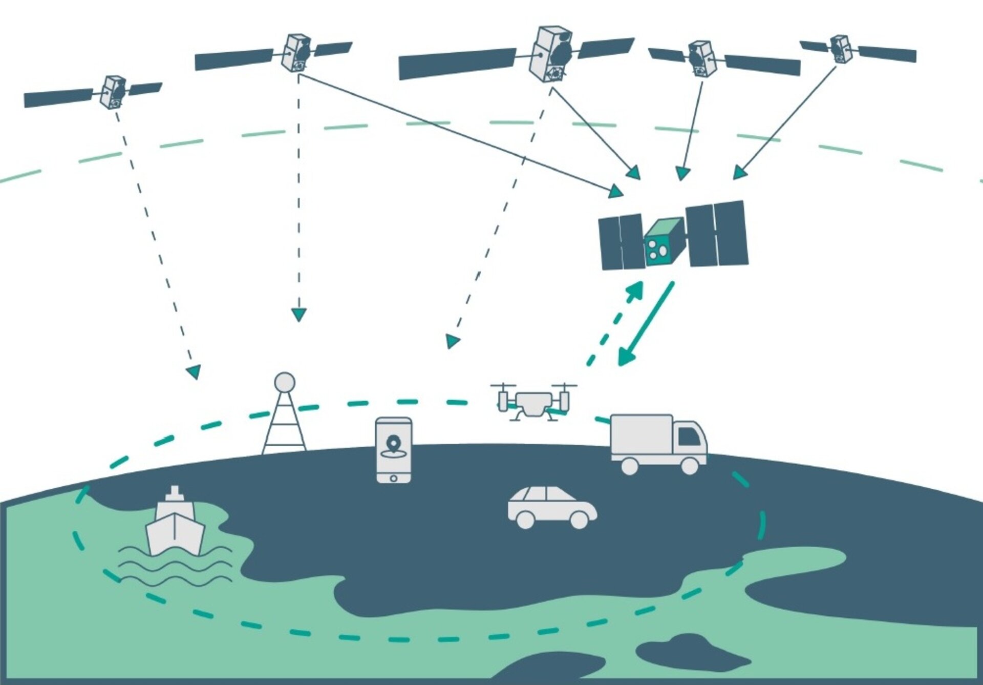
LEO satellites would supplement the existing Galileo constellation. (Image: ESA)
Better Performance Combining Fiber Optics and Wideband Radio
Innovation Insights with Richard Langley
“OH DEAR! OH DEAR! I SHALL BE LATE!” That’s what the White Rabbit said in the opening chapter of Lewis Carroll’s Alice’s Adventures in Wonderland just before checking the time on its pocket watch. Scientists at the European Organization for Nuclear Research (known by its French acronym CERN) named their project to develop an Ethernet-based network for general purpose data transfer and sub-nanosecond accuracy time transfer after the time-conscious rabbit. CERN’s White Rabbit (WR) can provide sub-nanosecond accuracy to synchronize more than 1,000 nodes via optical fiber or copper connections of up to 100s of kilometers in length. It is a flexible system with a scalable and modular infrastructure with a simple configuration and low maintenance requirements. It is also open source.
WR uses the IEEE 1588 Precision Time Protocol (PTP) to establish precise phase differences between a master reference clock and a local clock. A two-way exchange of PTP synchronization messages allows precise adjustment of clock phase and offset.
So, what has this got to do with GPS or more generally GNSS? Well, for one thing, a WR-based system can serve as a back-up for GNSS time transfer or even replace GNSS. For example, a multi-hop WR link has been installed to connect financial trading locations in Chicago and New Jersey over an approximately 1,350-kilometer distance. Stock markets and other financial institutions need to time-tag transactions with traceable synchronization to a high-accuracy time standard to the microsecond level or better and a WR link can easily provide that.
Another application of WR is in terrestrial positioning. As we know, one of the problems with GNSS positioning is its poorer performance in built-up areas compared to open ones due to blocked signals and multipath. Multipath signals from close-by reflectors can be particularly pernicious as they reduce pseudorange measurement accuracy and thereby increase position error. And another potential weakness of GNSS is its susceptibility to radio-frequency interference, jamming and spoofing. A positioning system using synchronized roadside radio transmitters could be a viable alternative to GNSS in urban areas. A team of researchers based in The Netherlands has developed just such a system. In this month’s column, they describe their system, which uses WR to synchronize the transmissions of wideband radio ranging signals, and how they are able to achieve decimeter-level position accuracy in multipath environments.
By Cherif Diouf, Han Dun, Gerard Janssen, Erik Dierikx, Jeroen Koelemeij and Christian Tiberius
GPS is undoubtedly the most popular system providing positioning, navigation and timing (PNT) services to a host of applications, industries and infrastructures. GPS is mass-adopted, has worldwide coverage, has an impressive up-time and can be used with a wide range of receiver devices, featuring low to high cost and low to high precision.
Despite its strengths, the system also has some weaknesses. For instance, the positioning performance provided by GPS in dense multipath environments, such as in urban canyons, is poor. This is due to the interaction between the desired line-of-sight (LOS) component and close-in multipath components of the GPS signal reflected or scattered by built-up surroundings. Moreover, GPS signals, due to their low received power levels, are fairly vulnerable to unintentional and intentional threats such as radio-frequency interference, jamming and spoofing.
Alternative solutions that may complement or back up GPS, and more generally any other GNSS, to achieve reliable PNT for critical services and infrastructure, such as first responders, telecommunication and power systems, are urgently sought after. Wide coverage area synchronization using White Rabbit optical fiber networks allows simultaneous Ethernet networking and dissemination of 100 picosecond-level accurate time and frequency signals over distances of hundreds of kilometers. Accurate time synchronization may be provided to large areas such as big cities through this technology.
Building on such an accurate system, we present a concept and demonstration of an innovative hybrid optical-wireless terrestrial networked positioning system (TNPS). The TNPS demonstrator uses a White Rabbit infrastructure to accurately synchronize the transmissions of wideband radio positioning signals by its ground-based transmitters (pseudolites) and achieves decimeter-level positioning accuracy in an urban road-like configuration.
SCALABLE FIBER NETWORK DISTRIBUTION
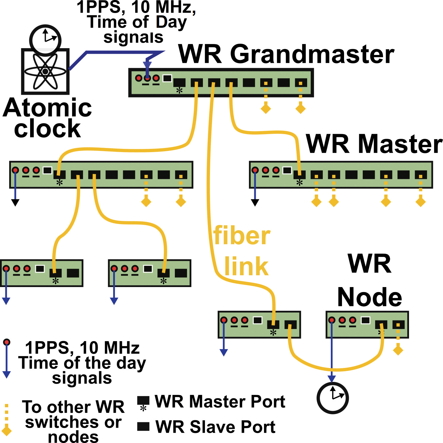
Initially developed for the Large Hadron Collider at the European Organization for Nuclear Research (CERN), White Rabbit (WR) is an accurate and scalable fiber-optic time and frequency transfer method that allows for dissemination of time references at sub-nanosecond level over distances of hundreds of kilometers. A typical WR network layout is shown in FIGURE 1.
FIGURE 1. Simplified topology of a White Rabbit (WR) network for optical time and frequency distribution. The yellow lines represent fiber-optic connections and the blue lines are electrical connections.
A central atomic clock provides synchronization references to a principal WR master switch dubbed the “grandmaster.” The grandmaster feeds synchronization signals into the network. which is expanded via fiber-connected WR devices: the switches and nodes of the network. These devices are serially linked to each other following a hierarchical master-slave pair configuration.
Accurate synchronization between a master and a slave WR-pair is performed as follows. The pair, which is connected via a bidirectional 1.25 gigabits per second optical Ethernet data link, quasi-continuously measures the round-trip delay of the data signals exchanged between the two devices. From these round-trip measurements, the one-way propagation delay, assumed symmetrical, is derived and compensated by the WR devices through an electronic control loop. To take into account possible asymmetries within a link, a calibration procedure is needed when initially installing the connection between a master and a slave. In practice, within smaller scale networks, the synchronization offset accuracy between devices is at the 100 picosecond-level. A 400-picosecond offset between WR devices has even been demonstrated over a distance of 169 kilometers, and more recently over a distance of 800 kilometers.
Besides the fiber-optic connection with other elements of the WR network, each switch or node can share its time-frequency references to an external device or system. These time-frequency references are available either in the form of IEEE 1588 Precision Time Protocol time stamps (via Ethernet connection), or in the form of electrical 1 pulse per second / 10 MHz synchronization signals (via coaxial cables).
THE CONCEPT
Centimeter- or even decimeter-level positioning accuracy is challenging to achieve using GNSS. In dense multipath environments, such as in urban canyons or indoor locations, the accuracy provided by GNSS is poor compared to the meter-level accuracy achievable in open terrain with the Standard Positioning Service. Moreover, GNSS services are vulnerable to interference, spoofing and jamming, and may be denied in indoor areas. We propose a TNPS based on a WR synchronization infrastructure as a complement to GNSS, providing higher timing and positioning accuracy, which also works in challenging environments.
TNPS can achieve decimeter-level accuracy in challenging environments through the use of wideband radio positioning signals. The attainable ranging precision is inversely proportional to the signal bandwidth. Furthermore, in dense multipath environments such as urban canyons, using wider bandwidth signals allows for finer time resolution. As a consequence, close-in received multipath components (MPCs) can be better resolved, and the LOS component can be more easily discriminated from delayed MPCs. This results in more accurate position solutions.
TNPS DEMONSTRATOR
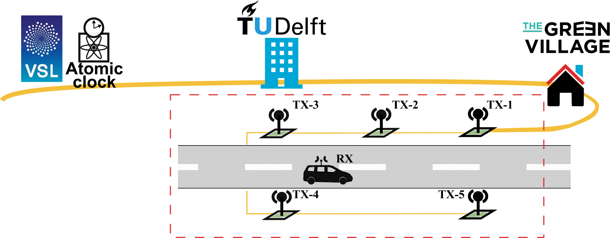
We performed a demonstration of the concept in Delft, The Netherlands, at The Green Village (TGV), an experimental facility on the campus of the Delft University of Technology. The facility aims to accelerate development and implementation of innovations for a sustainable future (see FIGURE 2).
FIGURE 2. Implementation of the TNPS demonstrator. The time-frequency reference is provided by VSL and forwarded to TU Delft via optical fiber (in yellow) and distributed through the optical WR synchronization infrastructure. Wireless radio transmitters (green squares) connected to the WR network deliver wideband ranging signals to perform terrestrial positioning and navigation.
The central synchronization reference of the TNPS demonstrator is the Dutch national timescale version of Coordinated Universal Time UTC(VSL), derived from atomic clocks at the Van Swinden Laboratory (VSL), the Dutch metrology institute. The UTC(VSL) 10 MHz frequency reference and 1 pulse per second time reference are fed to the WR grandmaster switch (WR-SW1). The grandmaster switch is subsequently connected to a distant WR switch (WR-SW2) through a 1,470-nanometer downstream and a 1,490-nanometer upstream 1.25 gigabit per second optical link. WR-SW2, located at one of the TU Delft data centers, synchronizes in turn a WR node (WR-N1) installed at TGV.
The remaining TNPS nodes at TGV are synchronized through a daisy-chain configuration. The first node (WR-N1) is connected to a second one (WR-N2), which is then connected to a third (WR-N3) and so on. In total, five timing nodes, WR-N1 to WR-N5, are connected to one another, using 50-meter optical fibers. These 5 timing nodes are used for synchronization (see FIGURE 3), and provide 1 pulse per second and 10 MHz electrical signals to five wideband radio transmitting units, uTX-1 to uTX-5, installed along a 50-meter stretch of road at TGV.
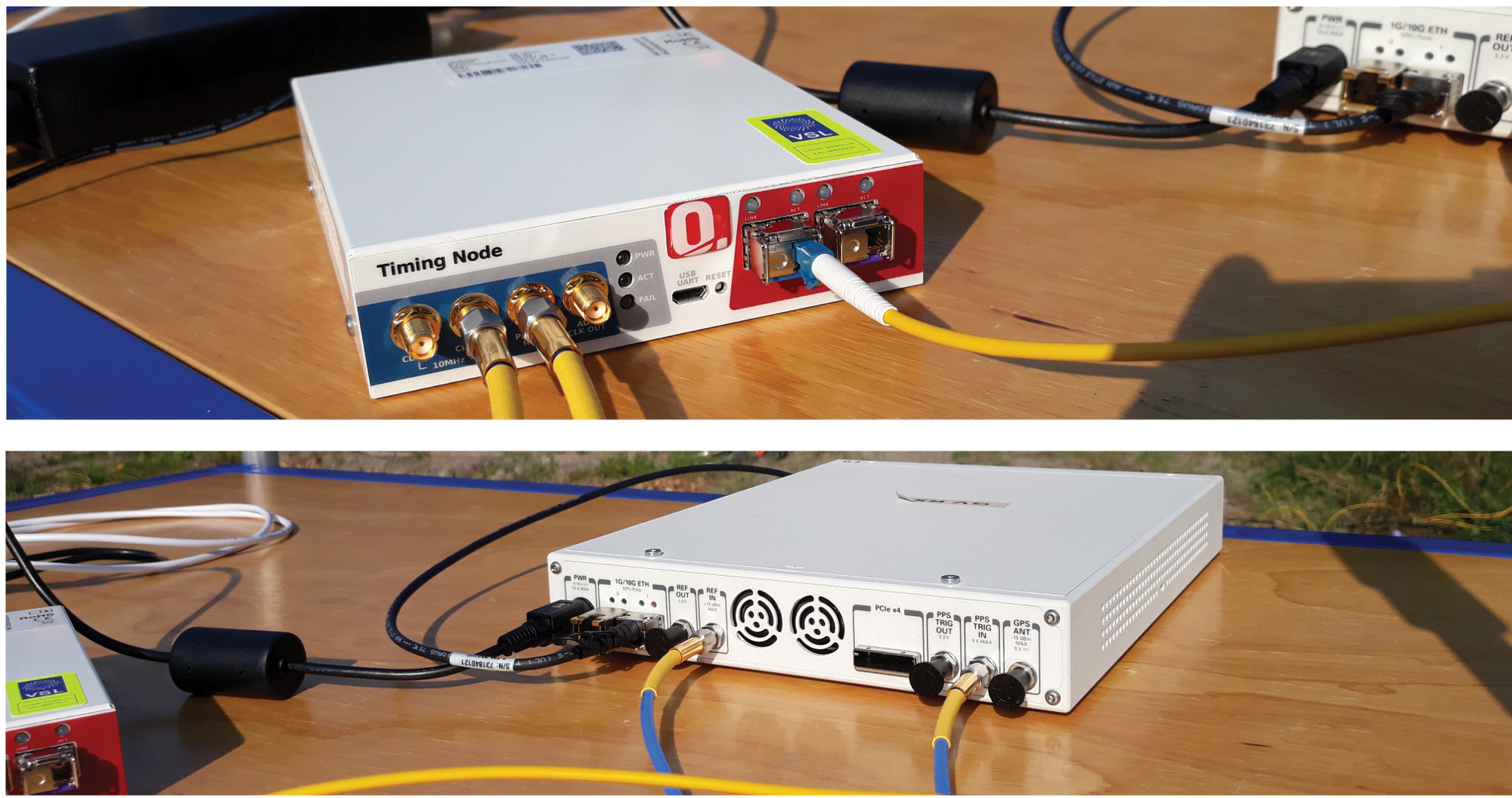
FIGURE 3. WR timing node (top) fed by a 1.25 gigabit per second bitstream through an optical fiber (yellow cable to the right) and providing electrical 1 pulse per second and 10 MHz synchronization signals at the outputs (two cables to the left). The bottom image shows an SDR system. The two channels of this device, capable of wideband operation, act here as a wireless transmitter or as a receiver. The transmitters are synchronized to the WR network through the 1 pulse per second and the 10 MHz electrical signals (blue-yellow cables at bottom) provided by the WR timing node.
A transmitting unit is based on a wideband transceiver: a software-defined radio (SDR) system linked to a wideband antenna that can operate from 700 MHz to 6 GHz. The antennas are connected to the SDRs using coaxial cables with a length of 5 meters and mounted on lampposts along the road at a height of about 4 meters. The transmitting units, uTX-1 to uTX-5, are respectively associated with antennas TX-1 to TX-5.
Each of these SDRs is capable of transmitting a wireless signal of up to 160 MHz bandwidth, on one or two of the device transmitter channels. The central frequency of each channel is tunable from 10 MHz to 6 GHz. In the demonstrator, we used a 3.96 GHz carrier frequency. The transmitting units periodically stream 160 MHz wideband quadrature phase-shift keying (QPSK) modulated pseudorandom noise (PRN) ranging signals sampled at 200 MHz. The five transmitters operate according to a time-division-multiplexing (TDM) scheme; uTX-1 to uTX-5 successively transmit the QPSK-modulated sequences as a 27.5-microsecond “burst” before turning idle. Between two successive transmissions, a guard interval of 3 microseconds is inserted during which all transmitting units are in idle state. It takes in total 150 microseconds for the five units to complete a transmission round, after which the units remain idle. The transmission round is then retriggered each millisecond.
At the receiver side (RX), another SDR platform is configured to acquire the QPSK modulated bursts transmitted by the five units uTX-1 to uTX-5. This SDR is actually playing the role of a data acquisition platform, which records and forwards the incoming sampled ranging sequences to the host PC via an Ethernet link. All processing and analysis in the demonstrator is performed offline, rather than in real time, using the collected ranging signals. The sampling rate of the acquisition platform is 200 MHz. A sample consists of a 16-bit in-phase value and a 16-bit quadrature-phase value (4 bytes in memory). In continuous operation, the SDR acquisition throughput would amount to 800 megabytes per second.
A throughput of 800 megabytes per second is difficult to handle for most of the host PCs. The SDR is therefore configured to only forward the relevant part of the data collected. Only the received samples time-aligned with the 150-microsecond transmitting window are periodically transferred to the host PC at a rate of 1 kHz. In practice, the acquisition window is slightly extended to 160 microseconds. Overall, the data throughput between the SDR and the host PC is now reduced to 128 megabytes per second; that is, 10 seconds of acquisition will generate a data file of 1.28 gigabytes.
A Schmidl & Cox synchronization sequence is embedded in the signal transmitted by uTX-1. The SDR field-programmable gate array continuously performs autocorrelation on the incoming samples and uses this sequence to detect the arrival time of the ranging bursts for operation in asynchronous mode. The receiver also can be operated in synchronous mode, that is, synchronized to a timing node.
TEST SETUP
We carried out experiments on a 50-meter-long and 6-meter-wide local road at The Green Village (see FIGURE 4).
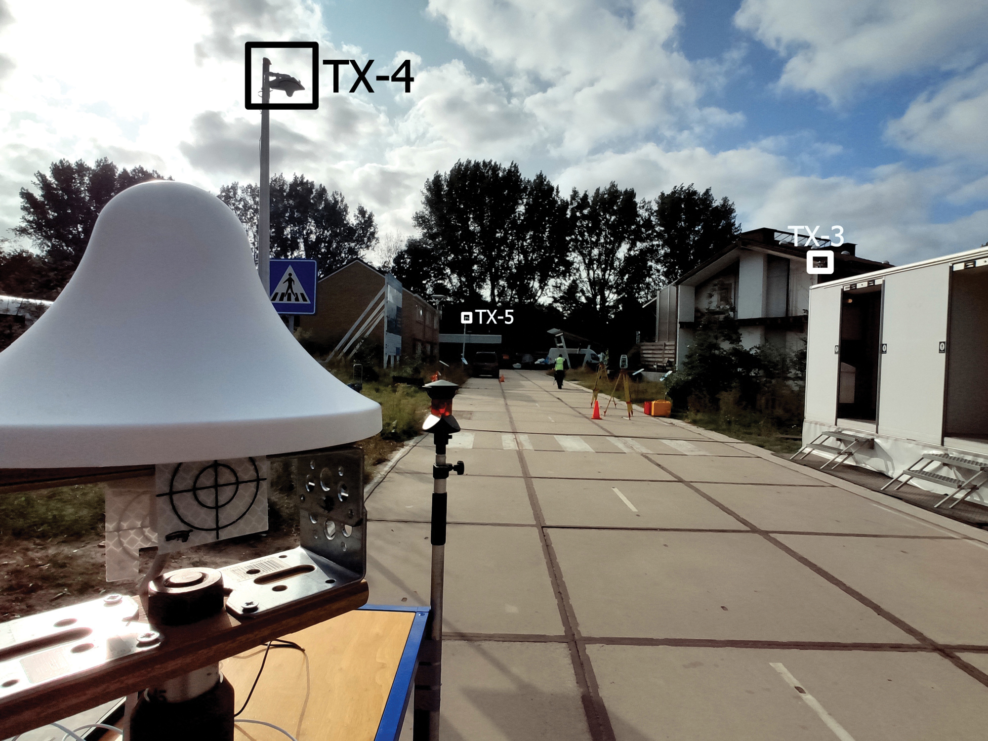
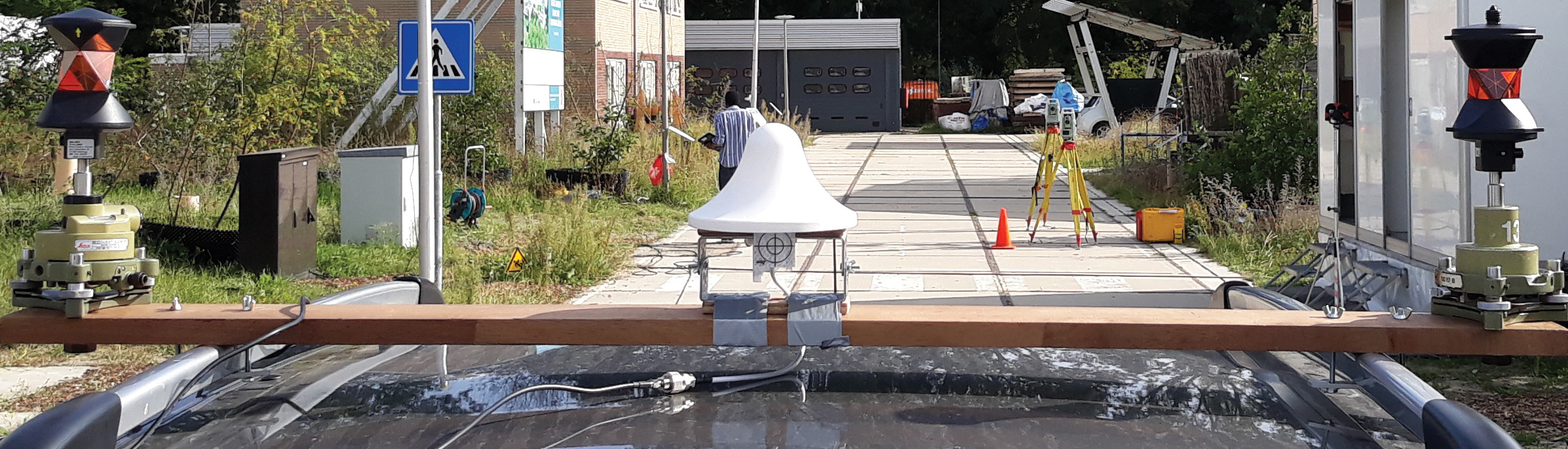
FIGURE 4. Test road at The Green Village, with three of the five roadside transmitting antennas (TX-3 to TX-5) as indicated. In the foreground, the receiver antenna is mounted on a trolley.
The road is bordered by built-up objects such as brick-wall houses, metal containers and large wooden advertising panels. These generate MPCs, which degrade the radio-positioning performance. The antennas TX-3, TX-4 and TX-5 can be seen mounted on lampposts. In Figure 4, the antennas TX-1 and TX-2 are on the right-hand sidewalk but not visible. The receiving antenna is in front to the left, mounted on a trolley. The RX antenna is identical to the ones used by the transmitters.
The receiver is used to perform a static survey at 50 locations on the road (staying at each point for around 1 minute). As shown in FIGURE 5, the receiver was also used for a kinematic experiment. The RX antenna is mounted on the roof of a car using a wooden beam. The RX antenna is linked via a 3-meter coaxial cable to the receiving SDR placed inside the car and connected to a host PC.
FIGURE 5. Receiver antenna mounted on the roof of a car. Two 360° prisms are used to determine the receiver ground-truth positions at the millimeter level, by means of land surveying total stations (placed on the yellow tripods in the distance).
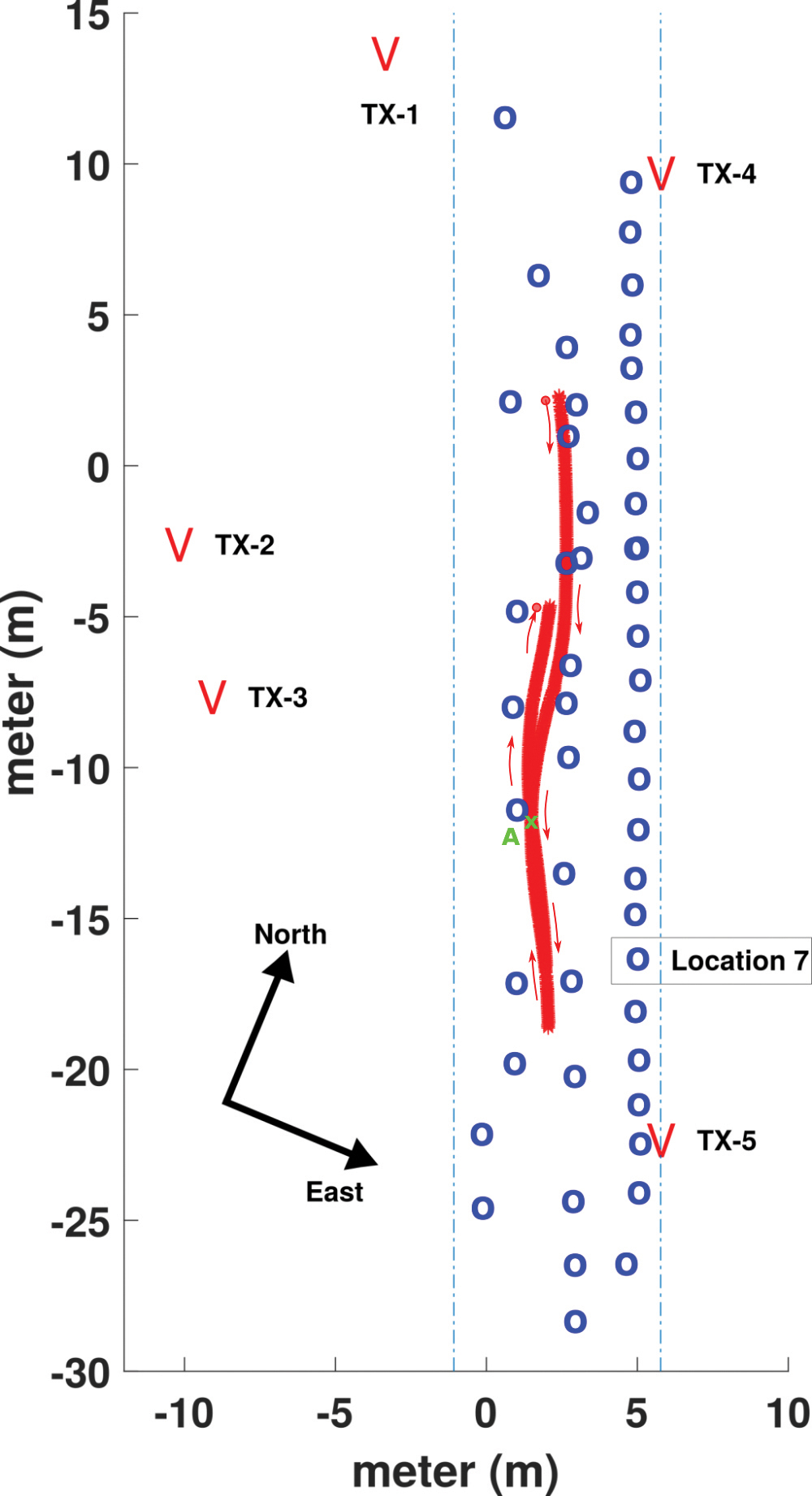
FIGURE 6 presents a map of the road with the static locations (in blue) and the forth-and-back kinematic track (in red). The transmitting antenna positions are indicated at both sides of the road.
FIGURE 6. Setup of the experiment on the local road at TGV. The locations of the transmit antennas, TX-1 to TX-5, are shown. Locations of static surveyed points are in blue, and the track of the kinematic experiment in red, with the RX antenna mounted on the roof of a car.
To establish a local coordinate system, the ground-truth positions of the RX antenna are determined using two land surveying total stations that rely on retro-reflective targets and 360° prisms to measure distances and angles. In Figure 4, a retro-reflective target, placed directly under the RX antenna, is visible, while the two total stations can be seen halfway down the road on the righthand side. In Figure 5, 360° prisms can be seen on both ends of the wooden beam on the roof of the car. The received signals are used to compute position solutions in post-processing, which are compared to the ground-truth values to assess the positioning accuracy. The accuracy of the ground-truth measurements is at the millimeter-level.
EXPERIMENTAL RESULTS
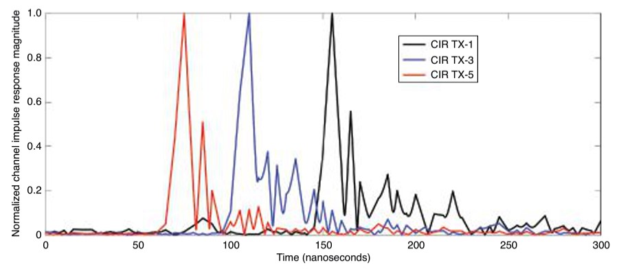
Achieving high positioning accuracy in a built-up area is difficult due to the presence of close-in MPCs, which arrive with very short time delays following the LOS component. FIGURE 7 shows the observed channel impulse responses (CIRs) between TX-1, TX-3, TX-5 and the receiver antenna RX placed at location 7 (see Figure 6). The LOS components can be easily detected as they correspond to the first and highest peak of each curve. However, we can also observe substantial close-in multipath components, which trail the main peaks. CIRs are obtained by division, in the frequency domain of the fast Fourier transform (FFT) of the received ranging sequences using the FFT of the known transmitted sequence. Oversampling by a factor of 100 is applied, as well as removing time delays of the TDM-scheme, such that the observed time delay difference directly represents the differences in ranges.
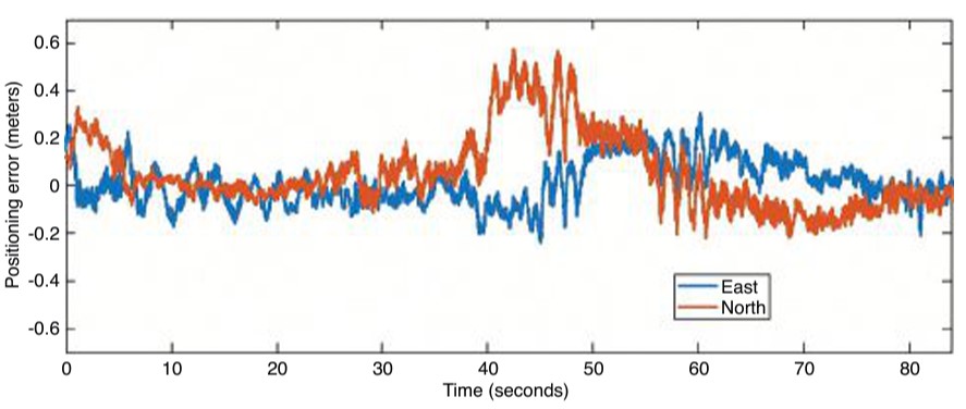
FIGURE 7. Normalized magnitude of the CIRs observed between the transmit antennas TX-1, TX-3 and TX-5 and the receiver antenna RX, positioned at reference point 7.FIGURE 8. Time series of the positioning error in the east and north directions during the kinematic experiment.
Since the TNPS signal bandwidth is 160 MHz, the time resolution is about 6.25 nanoseconds, which corresponds to about 1.9 meters of propagation distance. A multipath component, which arrives at the RX antenna with a lag larger than 6.25 nanoseconds with respect to the LOS component, is likely to be resolved and will not affect (bias) the ranging result. In this case, using time-of-flight techniques, ranges between TX and RX antennas can be determined, often at decimeter level, by extracting the time-of-arrival of the LOS components. Comparatively, if a 20 megasamples per second rate is used (corresponding to a 20 MHz bandwidth, commonly used in GNSS), the time resolution is 50 nanoseconds. An LOS component and a multipath component arriving at the RX antenna can likely be discriminated if the receiver and the reflector are separated by at least 15 meters. If the arrival time between the two components is less than 50 nanoseconds, then the MPC cannot be resolved and will cause a bias when determining the propagation distance between the TX and RX antenna.
The first and largest peak of each CIR seen in FIGURE 7 represents the LOS component. MPCs can be seen trailing the LOS, typically within the next 50 nanoseconds. The MPCs cause a bias in the estimated range when they cannot be resolved. Using wideband ranging signals allows for better time resolution, and better discrimination between the LOS component and the MPCs.
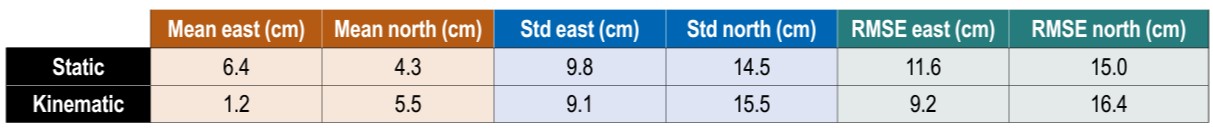
In the following, we assess the 2D positioning accuracy obtained using the demonstrator. 3D positioning is also possible with the demonstrator; however, since the TX antennas all are installed at similar heights and at a fairly low elevation compared to the RX antenna, we restrict our analysis to 2D positioning for the reason of having a poor geometry for determining the vertical position component. The 2D positioning model uses time difference of arrival (TDOA) pseudoranges allowing the cancellation of the asynchronous receiver clock offset. The frequency offset between the transmitters and the receiver has been estimated to be about 1 kHz, in asynchronous mode. After the TDOA ranges are computed from the experimental data, the 2D positioning problem is solved through Gauss-Newton iteration. Statistics of the static and kinematic 2D experiments are presented in TABLE 1.
TABLE 1. Static and kinematic positioning performance in terms of mean, standard deviation (std) and RMSE of position error, in east and north directions.
In the table, we present the mean position errors, standard deviations and root-mean-square errors (RMSEs) over the 50 surveyed points for the east and north directions. Mean errors of 6.4 and 4.3 centimeters are obtained for east and north directions, respectively. There is no significant bias in the system. In terms of RMSE, we can see that the positioning accuracy is just above 10 centimeters (11.6 and 15 centimeters respectively for the east and north directions). Overall, even with the presence of MPCs, and thanks to the synchronization accuracy and the wideband radio signals, a decimeter-level accuracy is achieved in static positioning.
The duration of the kinematic experiment was 84 seconds. Looking at the statistics of the kinematic experiment, the results for the east and north directions show a small bias and RMSE values of 9.2 and 16.4 centimeters respectively. The positioning performance in static and kinematic mode is close, both for the east and north components. In both cases, positioning performance is better in the east direction than in the north direction. This may be explained by better spatial diversity of the antennas towards the east direction. The time series of the position errors for the kinematic experiment is presented in FIGURE 8. Overall, the track error in the eastern direction is within ±2 decimeters (at a 95% confidence level). For the northern direction, a larger deviation is observed in the observation time span from 40 to 50 seconds (forward track), where the error in the north direction is close to 4 decimeters. Such a deviation is likely due to close-in MPCs resulting in a degradation of the accuracy for that part of the track. As a consequence, 82% of the position error in this track lies within ±2 decimeters. Outside this time span, the performance in east and north directions is similar.
CONCLUSIONS
This article presents the concept and results of a demonstration of a TNPS that uses WR to synchronize the transmissions of wideband radio ranging signals to achieve decimeter-level position accuracy in multipath environments, such as in built-up areas. A proof of concept of the TNPS was implemented at TU Delft. The developed prototype system demonstrates a decimeter-level 2D positioning accuracy in an urban road-like configuration bordered by built-up surroundings that cause substantial multipath.
ACKNOWLEDGMENTS
The research described in this article is supported by the Dutch Research Council, Nederlandse Organisatie voor Wetenschappelijk Onderzoek. We thank Lolke Boonstra and Terence Theijn from TU-Delft ICT-FM, as well as Rob Smets of SURF, the collaborative organization for ICT for Dutch education and research for their support and expertise on the optical infrastructure, and Loek Colussi and Frank van Osselen of Agentschap Telecom and René Tamboer and Tim Jonathan of The Green Village for their support in realizing the SuperGPS demonstrator. We also thank project partners Koninklijke PTT Nederland (KPN), Optical Positioning Navigation and Timing (OPNT) and Fugro.
MANUFACTURERS
The WR timing nodes V1.15 are by OPNT. The SDR systems for the transmitters and receiver are National Instruments (Ettus) X310 Universal Software Radio Peripherals. The 3-dBi wide-band antennas CM.02.03 are from Taoglas.
CHERIF DIOUF was a postdoctoral researcher in the Department of Geoscience and Remote Sensing at Delft University of Technology (TU Delft).
HAN DUN was a Ph.D. student in the Department of Geoscience and Remote Sensing at TU Delft.
GERARD JANSSEN is an associate professor in the Circuits and Systems Group of the Microelectronics Department at TU Delft.
ERIK DIERIKX is the principal scientist at Electricity & Time at the national metrology institute VSL in Delft.
JEROEN KOELEMEIJ is an assistant professor in the Department of Physics and Astronomy at the Vrije Universiteit Amsterdam.
CHRISTIAN TIBERIUS is an associate professor in the Department of Geoscience and Remote Sensing at TU Delft.
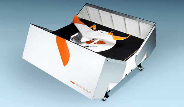
The Avy Aera departs from its docking station within minutes, shortening response times and reducing costs for first responders. (Photo: Avy)
Dutch company Avy has launched its Drone Response Network, combining docking stations with autonomous aircraft that have vertical take-off and landing (VTOL) capabilities.
The network offers drone coverage in a certain area, enabling instant deployment to support medical deliveries or emergency services during critical incidents.
First flights are expected to take place in the first quarter of 2022.
The network uses the Avy Aera autonomous drone that can carry up to 3 kg of medical goods over a distance of 100 km. It can operate year round, in rain and winds up to 45 kph, and is designed to meet the latest European Union drone regulations and United Nation requirements for aerial transport of medical goods.
For medical delivery, the drone is equipped with Aera’s Medkit, which has a four-liter capacity and is fitted with sensors for immediate assessment. Medical products remain cooled at 2-6 degrees for at least 100 minutes in an ambient temperature of up to 40° C.
The Avy Drone Response network is suitable for both urban and rural areas, delivering medicines, blood products, vaccines and other medical applications safer and twice as fast as road transportation, and is more environmentally friendly. It is expected to make a substantial contribution to achieving the goal of connecting hospitals and laboratories by air by 2023.
The Avy Aera can also be integrated with a high zoom RGB and thermal camera system and used to quickly detect wildfires, spot people in distress at sea, monitor oil spills and assess the situation on the ground.
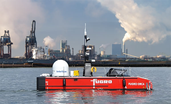
Fugro’s Blue Essence, an offshore certified uncrewed surface vessel (USV) with an electric remotely operated vehicle (eROV), will begin its first project in the Netherlands.
The vessel is controlled from an onshore remote operations center (ROC) via a satellite connection. It will be used for the inspection of offshore assets, construction support services, and hydrographic and geophysical surveys.
USVs play an important role in the future of the maritime sector by improving safety, reducing carbon emissions, and delivering data more efficiently. USV operations remove personnel from high-risk offshore environments to an onshore ROC and reduce carbon footprint by 95 % when compared to traditional survey methods. Cloud-based data processing allows near real-time data delivery, leading to faster and more informed decision making.
“We welcome this special vessel in our port. It’s the first time a remotely controlled uncrewed vessel will go to the North Sea from the port of Rotterdam to carry out a project without any personnel on board,” said René de Vries, Harbour Master of the Rotterdam Port Authority. “We are proud that this project will be executed safely due to the careful preparation of all parties involved. We expect the development of digitalization in the shipping sector will improve the safety and accessibility of the Rotterdam port.”
Since 2020, Fugro has been deploying its Blue Shadow USV fleet for medium- to large-scale hydrographic survey applications. Fugro’s first Blue Essence has completed its first remote inspection, in Asia Pacific.
“I am excited that we now also have this newest generation of USVs available for European clients,” said Erik-Jan Bijvank, group director Europe and Africa at Fugro. “Over the coming years, Fugro will further expand its fleet of USVs for safer, more sustainable solutions for marine operations.”
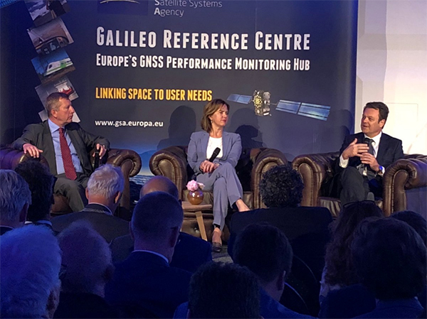
The Galileo Reference Centre (GRC), the new state-of-the-art performance monitoring hub for the European Union’s global satellite navigation system, was officially inaugurated May 16 in Noordwijk, the Netherlands.
The ceremony was presided by Dutch Minister of Infrastructure and Water Management Cora van Nieuwenhuizen and European GNSS Agency (GSA) Executive Director Carlo des Dorides, among others.
GSA Executive Director Carlo des Dorides (right), Dutch Minister for Infrastructure and Water Management Cora van Nieuwenhuizen, and DG GROW Deputy Director-General Pierre Delsaux at GRC inauguration. (Photo: GSA)
“The Galileo Reference Centre is a state of the art facility that underpins Galileo service provision,” des Dorides said. “The GRC will be instrumental in monitoring the performance of the system and of the service operator, ensuring that users benefit from the most reliable satellite data and, at the same time, disclosing new service potential.”
“I am proud of the fact that the Galileo Reference Centre is located in the Netherlands,” van Nieuwenhuizen said. “The data provided by Galileo will enable us to navigate with an accuracy to within 20 centimeters. In rescue operations, this sharp reduction in response time is going to save human lives.”
Independent monitoring ensures quality for users
The GRC is a cornerstone of service provision for Europe’s Galileo satellite constellation and plays an important role in Galileo’s operations, providing the GSA with an independent means of evaluating the quality of the signals in space and the performance of the Galileo Service Operator (GSOp). In so doing, it helps ensure the provision of high-quality satellite data so users can better rely on and benefit from Galileo.
Managed by the GSA, the GRC is comprised of a core facility in Noordwijk and contributions from EU Member States, Norway and Switzerland. From the core facility, the GRC generates performance evaluation products and reports using data collected in-house and through cooperation with Member States. The Centre also performs dedicated campaign-based analyses to support investigation of any service performance issues and reports on its findings.
In this two-pillar approach, the GRC benefits from and contributes to maintaining long-term competence and expertise at the Member State level, and actively integrates contributions from the EU Member States, Norway and Switzerland to support daily operations and specific campaigns.
The GSA has established agreements with two beneficiaries, one led by the French Space Agency (CNES) and the other by the Netherlands Aerospace Centre (NLR), and 23 organizations from 14 different countries. Member State contributions include data from networks of reference stations and campaigns using vehicles, vessels and airplanes, and reference products.
The GRC is fully independent of the system and the Galileo Service Operator with respect to its operations.
Since June 2017, GRC operations were hosted and operated from a temporary facility at ESTEC, the neighbouring ESA technical centre, which was instrumental in the swift ramp-up of competences. In April the GRC moved to its new home.
Earlier in May, the GRC hosted representatives from US GPS, Russian Glonass, Chinese BeiDou, Japanese QIS and Galileo to discuss the creation of an authoritative international GNSS monitoring and assessment system to benchmark the performance of available GNSS. The meeting was organised through the International GNSS Monitoring and Assessment Task Force of the United Nations Office of Outer Space Affairs (UNOOSA), International Committee on GNSS (ICG).
The Galileo Reference Centre (GRC), which will be established in the Netherlands, will play a crucial role in monitoring Galileo’s performance. The European GNSS Agency (GSA) made the announcement during this week’s European Space Solutions conference in The Hague.
With Galileo Initial Services set to be declared this year, the GRC will play a pivotal role in the programme’s operations, the GSA announced during the 4th European Space Solutions conference in The Hague.
The Galileo Reference Centre (GRC) will be established in Noordwijk, the Netherlands. The GRC’s core mission is to perform independent monitoring of Galileo’s performance and report on its findings.
GRC’s core facility in Noordwijk will also actively integrate contributions from the EU Member States Norway and Switzerland. The core facility is charged with generating performance evaluation products, reporting and performing dedicated campaign-based analyses. It will also rely on a range of facilities and expertise available in the Member States.
The GRC will be implemented using a versioning approach. The first step is expected to be in place at the time of declaration of Galileo Initial Services. The core facility is set to become operational in 2017.
“The use of space data is becoming more urgent and relevant in many areas, for example in maritime safety and smart mobility,” said Melanie Schultz van Haegen, Dutch Minister of Infrastructure and the Environment. “The Galileo Reference Centre will help ensure the provision of high quality satellite data so users can better rely on and benefit from Galileo.”
“When operational, the GRC will provide the GSA with an independent system to evaluate the performance of the Galileo Service Operator and the quality of the signals in space,” said GSA Executive Director Carlo des Dorides. Dorides and van Haegen were joined by Elżbieta Bieńkowska, European Commissioner for Internal Market, Industry, Entrepreneurship and SMEs, to officially sign the GRC hosting agreement during the conference’s opening session.
The GRC in Brief
Galileo is Europe’s global navigation satellite system (GNSS), operated and maintained by the Galileo Service Operator, under contract with the European GNSS Agency (GSA).
The Galileo Service Operator is responsible for ensuring that the programme complies with the Galileo Services performance requirements.
The Galileo Reference Centre (GRC) is one of the Galileo Service Facilities: a facility to support the provision of services to the Galileo Core System and the Galileo users.
The GRC is operated by the GSA: it provides the GSA with an independent means of evaluating the performance of the Galileo Service Operator and the quality of the signals in space.
The GRC is fully independent of the system and the Galileo Service Operator with respect to both the technical solution and operations
The GRC is comprised of both a core facility and contributions available at EU Member States, Norway and Switzerland.
The core facility, located in Noordwijk (The Netherlands), is charged with:
generating performance evaluation products and reports using data collected by itself and through cooperation with Member States;
performing dedicated campaign-based analyses to support investigations of service performance and service degradations;
making use of the GRC’s own data, products and expertise.
Data and products from cooperating entities from the Member States support both daily operations and specific campaigns.
The GRC should benefit from but also contribute to maintaining the long term competences and expertise at the level of Member States.
All of the components of the GRC will be implemented using a versioning approach. The first performance monitoring solution, which primarily relies on contributions from Member States, is expected to be in place at the time of declaration of Initial Services. The core facility is expected to become operational in 2017.
The latest variant of the Excalibur precision-guided projectile will be used by armies and be available for naval ships.
The Netherlands Ministry of Defense is adding Raytheon Company’s Excalibur Ib artillery rounds to its arsenal under a previously announced foreign military sales agreement, underscoring growing international interest in the precision-guided projectile.
The Netherlands is the second Excalibur lb customer in Europe after Sweden, the U.S. government’s development partner for the 155-mm round. Deliveries are expected to begin later this year.
“The Netherlands joins a growing list of nations acquiring this highly sophisticated artillery munition, which uses GPS guidance to provide accurate, first-round effects capability at extended ranges,” said Mark Hokeness, Raytheon’s Excalibur program director. “When fired from the Dutch PzH 2000 artillery system, Excalibur can fly up to 50 kilometers, score a direct hit and deliver lethal effects in all types of weather and battlefield conditions.”
A Dutch Panzerhaubitze 2000 (PzH 2000) fires a round in Afghanistan. (Image courtesy Dutch Ministry of Defense)
The U.S. Army has determined Excalibur Ib is fully compatible with the PzH 2000, a self-propelled howitzer produced in Germany and fielded by several nations.
The Excalibur precision-guided, extended-range projectile uses GPS guidance to provide accurate, first-round-effects capability in any environment. Excalibur’s level of precision delivers a major reduction in the time, cost and logistical burden associated with using other artillery munitions. Excalibur has been fielded by the U.S. Army, Marines and several international military forces.
Excalibur Facts
Combat-proven: Nearly 770 Excalibur rounds have been fired in combat with exceptional accuracy and lethality.
Precise: Excalibur consistently strikes less than two meters from a precisely-located target, Raytheon said.
Safe: Excalibur’s precision avoids collateral damage and has been employed within 75 meters of supported troops.
Affordable: With its first round effects, Excalibur reduces total mission cost and time and the user’s logistics burden, according to Raytheon.
Evolving: Raytheon has demonstrated a dual-mode GPS/semi-active laser seeker Excalibur variant to compensate for target location error, maintain precision in GPS denied or degraded environments, and enable engagement of relocated or moving targets.
Navies: With Excalibur N5, navies will be able to deliver extended range, precision naval surface fires from existing 5-inch/127-mm guns.