Author: Matteo Luccio

  • How machine control helps level, cut and dig in diverse environments

    How machine control helps level, cut and dig in diverse environments

    Photo: Leica Geosystems
    Photo: Leica Geosystems

    Machine control systems, which combine positioning sensors — both GNSS receivers and inertial systems — with computer displays, give operators better insight into and control over their work. Whether moving dirt on a construction site, spraying crops on a large farm, or moving cargo containers in a port, machine control increases efficiency and precision while decreasing accidents and fuel consumption.

    Machine control systems enable operators to accurately position buckets, blades and other implements on their machines without having to first survey and stake the work site, or having to constantly check their work. They give operators a clear reference between the position of the machine bucket or blade and the design surface, thereby increasing their productivity and accuracy. They also utilize labor and equipment efficiently to reduce costs and minimize wear-and-tear. Finally, by collecting data during their operations, they help teams communicate better and share models.

    Machine control, which first began to be implemented in the 1990s, is being increasingly adopted across a variety of different types of construction equipment — including graders, dozers, and, more recently, excavators. Now, beyond simply providing operators with a visual guide to the position of their buckets or blades, automated machine control moves the blade to grade by talking directly to the machine’s hydraulics, enabling new or less-skilled operators to perform like long-time professionals and increasing the speed and precision of even the most experienced operators.

    The three case studies in this cover story highlight the need for precision control of the implements on earth-moving machines, the importance of good data and the need to make the process as easy as possible for the operator.

    ComNav Technology

    Enhancing construction projects in the Maldives

    The Maldives consists of numerous coral reef islands with low soil-bearing capacity. Using heavy machinery in such an environment requires careful management of movement and precise operations while avoiding damage to local coral reef ecosystems, thus preserving marine life and the natural landscape of the islands.

    using heavy machinery among sensitive coral reefs requires careful movement and precise operations to avoid damaging them. Photo: ComNav
    using heavy machinery among sensitive coral reefs requires careful movement and precise operations to avoid damaging them. Photo: ComNav

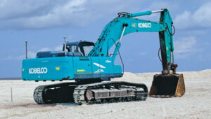
    As an advanced construction solution, ComNav Technology’s XE100 Guidance System for Excavator employs high-precision GNSS positioning and heading technology coupled with inertial sensors. In construction projects in the Maldives, the XE100 not only provides precise guidance for operators on land but also enables efficient and precise underwater operations in complex marine environments while minimizing ecological impact. Its excellent performance has brought significant benefits to construction projects in the Maldives.

    The Maldives’ construction environment is complex and variable, requiring precise equipment to adapt to diverse terrain. The XE100 supports multi-constellation multi-frequency GNSS, delivering centimeter-level accuracy. This ensures that, whether for leveling, slope cutting, or digging, the system delivers precise instructions for bucket operations and guarantees accurate excavator positioning, even in challenging conditions.

    ComNav technology’s Xe100 GNSS machine control system delivers centimeter-level accuracy in complex and variable environments. Photo: ComNav
    ComNav technology’s Xe100 GNSS machine control system delivers centimeter-level accuracy in complex and variable environments. Photo: ComNav

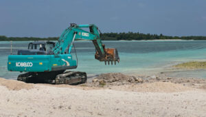
    For scenarios requiring underwater operations or mixed land and water tasks, the XE100 overcomes the traditional challenge of locating exact coordinates. The GNSS tablet’s intuitive display of coordinate points helps operators identify work areas and select appropriate excavation actions. This ensures safety, reduces technical barriers, minimizes the need for rework, and significantly enhances construction quality while maintaining high efficiency and precision.

    Construction projects in the Maldives often face challenges such as high humidity, high salinity and frequent vibrations. Each component of the XE100 is designed to withstand harsh environments with excellent durability. The system’s modular design also supports expansion to other construction machinery, enhancing flexibility and paving the way for future technological upgrades.

    As a nation abundant in marine resources and dependent on tourism, ongoing infrastructure development and maintenance are critical to the Maldives’ economy. The XE100 system improves construction accuracy, reduces operation time, ensures safety, and lowers costs, thereby accelerating project timelines.

    Leica Geosystems

    Machine control and automation for snow management

    The allure of pristine slopes and perfectly crafted terrain parks has always drawn adventurers to the mountains, but the landscape of snow management is shifting dramatically. With rising temperatures and unpredictable weather patterns, climate change poses a significant challenge to the snow sports industry. Natural snowfall is becoming less reliable, leaving resorts dependent on costly snowmaking systems that strain resources and budgets.

    Leica alpine office enables resorts to achieve operational goals while safeguarding the environment by precisely managing snow management and reducing waste. Photo: Leica Geosystems
    Leica Alpine Office enables resorts to achieve operational goals while safeguarding the environment by precisely managing snow management and reducing waste. Photo: Leica Geosystems

    For snowparks, these challenges are even more acute. Crafting intricate features such as halfpipes, jumps and rails requires precision and significant amounts of snow — an increasingly scarce resource. Amid these difficulties, the need for sustainability has never been more pressing.

    The tech that’s changing the game

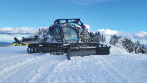
    Leica Geosystems’ snow management solution, the Leica iCON alpine, paired with Prinoth snow groomers, is helping resorts get more out of less, making the construction of snowparks more efficient and sustainable.

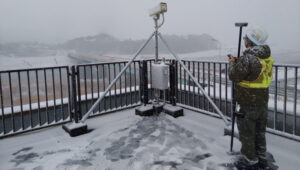
    The Leica iCON alpine system leverages GNSS and advanced inclination sensors and inertial measurement units (IMUs) to measure and manage snow depth accurately. Mounted on any snow groomer, this system continuously collects data, ensuring that operators can see the exact snow depth beneath the blade and tracks — accurate to within ±3 cm. In other words, it’s like X-ray vision for your snowcat.

    the leica icon alpine, paired with Prinoth snow groomers, is helping to make the construction of snowparks more efficient and sustainable. Photo: Leica Geosystems
    The Leica Icon Alpine, paired with Prinoth snow groomers, is helping to make the construction of snowparks more efficient and sustainable. Photo: Leica Geosystems

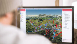
    Need a perfect jump? Create a 3D model and import the data, which can be read on the screen inside the groomer’s cab. It even handles tricky terrain with features like avoidance zones and anchor point searches. This setup doesn’t just make slopes look good; it helps operators work smarter, not harder.

    Snow measurement for World Cup Slalom course

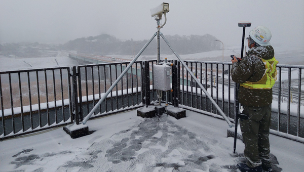
    For the past two years, Killington Mountain Resort in Vermont has been utilizing the Prinoth Connect Snow Measurement system powered by the Leica MC1 software.

    Killington is one of the first resorts in North America to invest in snow measurement, and it has been vital to executing the Women’s Slalom and Giant Slalom World Cup builds in 2023 and 2024. Killington has the snowmaking capability to cover the race trail, Superstar, with snow in about 100 hours. With the software, the teams can read the snow depth to +/- 3 cm, using snow measurement sensors instead of long metal probes. The software helps increase the efficiency of both snowmaking and grooming, making the build easier for the grooming operators, more straightforward for officials, and safer for the racers.

    Leica’s machine control solution has been vital to precisely executing the Women’s Slalom and Giant Slalom World Cup builds. Photo: Leica Geosystems
    Leica’s machine control solution has been vital to precisely executing the Women’s Slalom and Giant Slalom World Cup builds. Photo: Leica Geosystems

    From the snow to the dirt

    However, Leica Geosystems machine control technology is a year-round solution thanks to its versatile Leica MC1 platform, which allows the same hardware used for snow grooming to seamlessly transition into off-season applications such as summer earthworks, trail construction and road maintenance. With a single investment, resorts get a multipurpose tool that eliminates the need for separate systems, cutting costs and complexity.

    For instance, in the summer months at the Rieberalp in Davos Rinerhorn, the Leica MC1 solution powers excavation work for projects such as creating a reservoir and ensuring precise and efficient earthmoving. In the winter, the same system transitions to snow groomers, optimizing snow management on the slopes. This effortless switch between applications highlights the adaptability and value of the Leica MC1 platform, enabling ski resorts to get the maximum out of their investment while maintaining top performance year-round.

    Technology for more sustainable snowparks

    With precision snow management and reduced waste, resorts can achieve operational goals while safeguarding the environment. Adopting digital solutions such as these ensures that ski resorts and snowparks can continue to deliver world-class experiences for generations to come.

    Trimble

    Across digital dimensions on Te Ara Tupua

    Te Ara Tupua is an initiative by the New Zealand Transport Agency aimed at enhancing transport resilience while establishing a walking and cycling route between Wellington and Lower Hutt. The Te Ara Tupua Alliance includes the NZ Transport Agency and its design and construction partners: Downer NZ, HEB Construction and Tonkin + Taylor. To execute this project, the NZ Transport Agency is collaborating with Taranaki Whānui ki te Upoko o te Ika and Ngāti Toa Rangatira as iwi mana whenua. This collaboration inspired the name Te Ara Tupua, referencing the Māori creation story in which Ngake and Whātaitai, two tupua (ancient beings), formed Te Whanganui-a-Tara (Wellington harbor).

    The Ngā Ūranga ki Pito-One section of Te Ara Tupua will be built on the harbor’s edge, from Ngā Ūranga Interchange to Honiara Te Puni Reserve in Pito-One and connect with the new Pito-One to Melling section. The project will deliver a new resilient coastal edge protecting the road and rail while providing transport options and a safe route for walking and cycling between the two cities.

    The solutions involved include:

    • Trimble Marine Construction System
    • Trimble SketchUp
    • Trimble Stratus Software

    The benefits of the project include:

    • Reduced project timeline.
    • Improved safety for construction crews and the public.
    • Increased productivity.
    • Higher precision placement of embankment blocks.
    • Reduced environmental impact.
    • Real-time progress visibility for stakeholders.
    Te Ara Tupua will deliver a new resilient coastal edge protecting the road and rail while providing new and safer transport options. Photo: Trimble
    Te Ara Tupua will deliver a new resilient coastal edge protecting the road and rail while providing new and safer transport options. Photo: Trimble

    Te Ara Tupua is currently under construction along the western coastline of Te Whanganui-a-Tara with the aim of being completed in 2026. The Pito-One to Melling section of Te Ara Tupua is the first completed section of the project and was delivered by the contractors, Fulton Hogan.

    The Pito-One to Melling section is a 3 km separated cycling route stretching from Pito-One to the Hutt River Trail near Bridge Street. The new path eventually will join the Ngā Ūranga to Pito-One section of Te Ara Tupua, which connects to the Hutt Road and Thorndon Quay.

    The construction of Ngā Ūranga to Pito-One section of Te Ara Tupua includes a 4.5 km shared path, shared path bridge, rock revetments, seawalls and landings. To protect the shared path, road and rail line against wave action, erosion and sea-level rise, an essential part of the new pathway is the construction of embankments (or revetments).

    Underwater resilience

    Te Ara Tupua is the first project where seismic performance has been considered and tested in the design elements, including the new seawall built over a large active faultline.

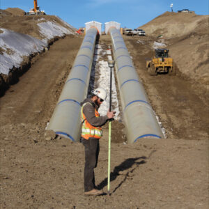
    Two main types of material are required for this project. Rock is being used for the revetment (the sloping rock seawall), which will protect the reclamation and the path from the sea while the remaining material is general fill. These are being sourced in Taranaki and Golden Bay with rock from Golden Bay being transported by barge, greatly reducing the number of truck movements.

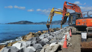
    XBlocPlus units are a unique cost-effective solution for Te Ara Tupua. These blocks are poured in the shape of an ‘X,’ which interlock and stack on top of each other to create a seawall with a steeper incline.

    Using these interlocking concrete blocks reduces the seawall’s physical footprint and impact on the marine environment, enabling the project to use less material at a lower cost compared to a rock revetment.

    Through this innovation, the project team of engineers and ecologists (Te Ātiawa, Ngāti Maniapoto, Ngāti Tūwharetoa and Ngāti Apa) worked alongside lead cultural designer, Len Hetet to combine cultural and environmental design, which resulted in Te Ripowai, the unique Te Ara Tupua ecological XblocPlus unit. Te Ripowai speaks of the rippling water and connects to a Te Ātiawa whakatauki of guardianship. The guardians must keep the ripples occurring, else water becomes still and life will cease to exist. Te Riopowai includes surface patterns and textures to encourage growth of marine plants.

    The Ngā Ūranga to Pito-One pathway shoreline ultimately will have 6,663 of these blocks of varying shapes.

    operators of excavators with grapple attachments needed to move eight different block shapes into place with an 80 mm tolerance. Photo: Trimble
    operators of excavators with grapple attachments needed to move eight different block shapes into place with an 80 mm tolerance. Photo: Trimble

    Block placement

    Placing these blocks with precision and speed initially created some concern for the project team. Operators in excavators equipped with grapple attachments needed to move the units into place, initially about 4 m underwater, to a tolerance of about 80 mm to assure embankment strength. To further complicate the construction, there are eight different block shapes.

    It’s a task purpose-built for real-time digital twins and machine guidance, according to the Alliance. With help from SITECH, the survey team looked to its digital assets.

    First, Jan du Preez, survey manager with the Te Ara Tupua Alliance, relied on Trimble SketchUp to accurately model the individual blocks. Then, the team combined the Trimble Marine Construction (TMC) System with a digital model of the excavator. Laser scans along the shoreline provided a digital record of the existing conditions. Even the sequential placement of the blocks is planned in the digital space.

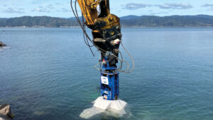
    On the job, an operator selects a designated block for placement on the screen, then uses the excavator grapple attachment to pick it up. TMC provides real-time feedback on the block’s position, rotation and tilt as the operator navigates to the appropriate position, even underwater.

    Du Preez added, “With TMC, the operators can ‘see’ where they are placing them under the water. Because they’re working in an active tidal area with most of the blocks sitting underwater, the idea was to make the process as easy as possible for the operator with highly visual markers on the screen. Every step is color coded, which allows operators to just focus on the colors, rather than trying to see underwater with the naked eye.”

    As the block is placed within the 80 mm tolerance required to interlock with the blocks above, the operator records the as-built position, and the screen shows green. The operator then releases the grapple and moves on to the next block.

    When asked about efficiency, du Preez noted, “The initial program specified placing 15 blocks per day. We are currently placing between 35 to 45 blocks per day depending on site conditions. We estimate that we’re seeing about three times the productivity compared with more conventional methodology — though I’m still not sure how we would have done this without TMC. We would have had to come up with some kind of visual marker and then perform quality checks with divers. It would have been time consuming and very costly.”

    Shared progress

    The benefits of the digital workflows to stakeholders, according to du Preez, are many, with transparency being the overarching benefit.

    Unlike a traditional contract where owner and project team are separate, in an alliance model the client is an integral part of the team. That said, while NZ Transport Agency, Waka Kotahi, et al., are involved in the everyday running of the project as part of the alliance, they also have a board. “Every time the Alliance board of directors sees our solution, they are completely blown away by what we’ve been doing and how we’re doing it,” du Preez said. They particularly like the regular drone flights that capture progress updates.

    “All survey data, models and regular flight imagery are loaded and stored in Trimble Stratus for sharing so that stakeholders always see the latest project status. The entire Alliance really appreciates this level of real-time digital visibility into the project.”

    Ngā Ūranga ki Pito-One is on track for completion in 2026. When complete, the Te Ara Tupua will deliver a safe, connected and resilient route, enabling more people to walk or bike, and connect with local paths in both Wellington and the Hutt Valley.

  • First Fix: Freeing CRPAs

    First Fix: Freeing CRPAs

    Figure 4: Illustrative beam patterns of a CRPA antenna in the presence of jamming (Figure: Michael Jones)
    Illustrative beam patterns of a CRPA antenna in the presence of jamming (Figure: Michael Jones)

    Controlled Reception Pattern Antennas (CRPAs, pronounced “serpers”) are still the single most effective counter to the threat to GNSS from jamming and spoofing — a growing problem in and near conflict areas, such as Ukraine and the Middle East. CRPAs, which make use of the fact that the desired satellite signals and the unwanted jamming signals generally arrive from different directions, reduce the effective range of jammers by up to five orders of magnitude. They are attractive because they replace existing antennas on GNSS receivers without requiring any other changes — though they are generally larger than typical GPS antennas because they contain several antenna elements and some associated electronics.

    Beginning on Sept. 15, 2025, CRPAs will no longer be covered by the International Traffic in Arms Regulations (ITAR), which prohibit the sale outside of the United States of defense articles, services and technical data and impose very large penalties for violators. ITAR is managed by the Directorate of Defense Trade Controls (DDTC) in the Bureau of Political-Military Affairs at the U.S. Department of State, which announced the rule change in mid-January. It removes items that “no longer warrant inclusion” from the U.S. Munitions List (USML), which defines the “defense articles” that fall under ITAR jurisdiction. CRPAs for PNT will instead be classified as dual-use commercial items and fall under the Export Administration Regulations list managed by the Department of Commerce. The Directorate removed CRPAs for PNT from the USML because they “no longer provide a critical military advantage, with increasing commercial utilization applicable to civil GPS resiliency” and because the department “intends to facilitate civil global navigation system resiliency.”

    This is a seismic shift that many in the GNSS/PNT community — including the National Space-Based Positioning, Navigation and Timing Advisory Board (PNTAB) — have been advocating for years. While U.S. manufacturers have been prohibited from exporting CRPAs, TUALCOM, a Turkish company based in Ankara, has been selling 4- and 8-element CRPAs for GNSS applications, as have some Canadian companies.

    Airlines and manufacturers of autonomous vehicles will be among the early beneficiaries of this policy change, as will many safety-of-life applications. Presumably, the vast expansion in the market for CRPAs also will quickly lead to a sharp drop in their cost.

    In a November 2022 presentation to the PNTAB, Brad Parkinson listed the use of CRPAs among the major techniques that can make GPS receivers “virtually immune” to jamming and spoofing, recalling that they were first tested in 1978. However, he pointed out, they had been neglected because they were perceived as too expensive and large for many applications, because of delays in implementing the L5 signal, and because ITAR prohibited beam-steering antennas with more than three elements. He argued that restrictions on GNSS CRPAs were no longer effective at preventing potential enemies of the United States from using them.

    Barring a reversal from the new administration, U.S. CRPA manufacturers can now help protect GNSS worldwide from jamming and spoofing.

  • JNC 2024: oneNav

    JNC 2024: oneNav

    Paul McBurney, co-founder and CTO of oneNav, met with Matteo Luccio, GPS World editor-in-chief, to discuss the benefits oneNav’s L5-direct GNSS technology has for alternative navigation in military applications.

    Discover more about oneNav’s L5-direct GNSS technology.

  • PNT Advisory Board hears reports on GPS, Galileo, QZSS and KPS

    PNT Advisory Board hears reports on GPS, Galileo, QZSS and KPS

    The National Space-Based Positioning, Navigation, and Timing Advisory Board continued its discussions on how best to protect, toughen and augment GPS at its 31st meeting, which took place Dec. 4-5 at the Sonesta Redondo Beach and Marina in Redondo Beach, California. The meeting was convened by James J. Miller, of NASA, who is the board’s executive director, and chaired by retired Adm. Thad Allen of the U.S. Coast Guard.

    On the first day, after hearing reports from its six subcommittees, the board heard the following presentations:

    • Karen Van Dyke, director, PNT & spectrum management, Department of Transportation (DOT), on DOT’s IDM and complementary PNT work.
    • Maj. Christine Bonniksen, retired from the U.S. Air Force, deputy director for flight projects, NASA Langley Research Center, and Shachak Pe’eri, Ph.D., acting director, National Geodetic Survey, National Ocean Service, National Oceanic and Atmospheric Administration (NOAA), on NOAA’s implementation of a GDGPS-based GPS High Accuracy and Robustness Service.
    • Anh Nguyen, Ph.D., NASA flight opportunities program (Bryce Space and Technology, LLC) and Lisa Valencia, NASA Space Communications and Navigation Program (Overlook Systems Technologies, Inc.) on the SpaceLoft 15 multi-GNSS flight experiment (see the article on p. 16).
    • Allison Kealy, Ph.D., director of the Innovative Planet Research Institute, Swinburne University, Australia, on resilient PNT.
    • Brad Parkinson, Ph.D., the board’s first vice chair, on a comparison of GPS with the other GNSS.
    • Satoshi Kogure, senior chief officer of satellite navigation technology, Japan Aerospace Exploration Agency on Japan’s Quasi-Zenith Satellite System (QZSS).
    • Moon Beom Heo, Ph.D., executive director of KPS R&D Directorate, Korea Aerospace Research Institute on the Korean Positioning System (KPS).
    • Matt Higgins, international engagement subcommittee chair on Galileo.
    • Cordell DeLaPena, executive officer, MilComm & PNT, Space Systems Command, USSF on the status of the GPS program, including L5, OCX, civil signal monitoring, resilient-GPS and low-Earth orbit PNT.

    On the second day, the board held a roundtable discussion, then heard updates from its international members and representatives. For video of the proceedings, go to youtube.com/@nationalpntboardmeetings822/streams.

    To celebrate Allen’s long service as this board’s chair, NASA conferred a beautiful plaque to him, bearing the following text:

    “PRESENTED TO Admiral Thad Allen
    With our deepest gratitude, the NASA community and our many partners are very thankful for the friendship and dedicated leadership you have provided as the Chair of the National Space-Based Positioning, Navigation, and Timing Advisory Board. Your advocacy on behalf of GPS users worldwide will always be remembered and cherished. December 2024
    Kevin Coggins
    Deputy Associate Administrator, Space Communications and Navigation
    NATIONAL AERONAUTICS AND SPACE ADMINISTRATION”

  • JNC 2024: Septentrio

    JNC 2024: Septentrio

    Jan Van Hees, vice president of business development and product management at Septentrio, talks about the Joint Navigation Conference (JNC) 2024 and Septentrio’s jamming and spoofing solutions.

  • A special welcome to the GPS World Editorial Advisory Board

    A special welcome to the GPS World Editorial Advisory Board

    I am very pleased to announce that professor Washington Yotto Ochieng has agreed to join our Editorial Advisory Board.

    He is the current head of the department of civil and environmental engineering and chair professor in positioning and navigation systems at Imperial College London, where he has been on the faculty since 1997. He is also the interim director of the college’s Institute for Security Science and Technology. Among his several other current roles, he is the president of the Royal Institute of Navigation, formed in 1947 following the example of the U.S. Institute of Navigation; a member of the board of trustees of the Science Museum Group appointed by the UK prime minister; and chair of the advisory board of the Science Museum in London.

    For a much longer bio of Ochieng, including his full list of titles and honors, visit here.

    GPS World featured Ochieng in its May 2009 issue, in a special section on “GNSS Leaders to Watch.” We wrote that he was “excited by the potential benefits of the new signals from modernized and new signals, and their integration with novel terrestrial systems/sensors.”

    He has proposed the following question for EAB discussion:

    When we discuss the security of GNSS/PNT systems, we nearly always focus on interference — i.e., meaconing, intrusion, jamming or spoofing. However, GNSS/PNT systems are embedded in systems of systems that also offer many other opportunities for cyberattacks. What should we do about it?
    We will publish responses from other EAB members in the next issue.

    Finally, our heartfelt thanks to Terry Moore and Jean-Marie Sleewaegen, who resigned from the EAB, for their many contributions over the years, and a special thanks to Jules McNeff, who has served on the EAB since the magazine’s inception 35 years ago!

  • First Fix: War, collaboration and elections

    First Fix: War, collaboration and elections

    (Photo: Jirapong Manustrong/iStock / Getty Images Plus/Getty Images)
    (Photo: Jirapong Manustrong/iStock / Getty Images Plus/Getty Images)

    In February 1991, two Russians joined this magazine’s Editorial Advisory Board: Nocolay Ivanov, Ph.D., research and development director of the USSR’s Institute for Space Device Engineering, and Gennady Gromov, Ph.D., chief designer general for the Leningrad-based All-Union Scientific Research Institute for Radio Equipment. Both were leading experts in GLONASS.

    In October 1982, 4 1/2 years after the launch of the first GPS satellite, the Soviet Union had launched the first test satellite for its new constellation. It peaked in 1996, with more than two dozen operating satellites in orbit, then declined, hitting a nadir of just seven operational satellites in 2001.

    Additionally, early GLONASS satellites were plagued by orbital failures and short lifetimes. Many observers wrote the system off as another victim of the economic and political disarray following the collapse of the Soviet Union. Then, the new Russian government reversed the trend by substantially increasing its funding for the program. By October 2011, the full orbital constellation of 24 satellites was restored. Next year, Russia plans to launch Glonass K-2, the latest generation of GLONASS satellites.

    Following Russia’s invasion of Ukraine, however, much international scientific and technical cooperation with the country has been on hold. On April 8, 2022, the European Commission declared: “Following the Russian invasion against Ukraine and in solidarity with the people of Ukraine, the Commission has decided to suspend the cooperation with Russian entities in research, science and innovation.” Two months later, on June 11, 2022, the White House followed suit: “Consistent with U.S. domestic and international law, we will wind down institutional, administrative, funding, and personnel relationships and research collaborations in the fields of science and technology with Russian government-affiliated research institutions.”

    By contrast, cooperation between the U.S. and European space agencies continues apace, as evidenced by a recent successful test of the interoperability of GPS and Galileo receivers.

    Meanwhile, in 2024, China reached a total of 45 operational BeiDou satellites in orbit. It is also conducting research on BDS technology upgrades and technological trials for integration with low-Earth orbit PNT systems. It touts this, together with its active participation in the work of relevant United Nations bodies, as enhancing international collaboration.

    At the latest two-day meeting of the National Space-Based Positioning, Navigation and Timing Advisory Board, in early December, much of the agenda was devoted to updates on international GNSS capabilities — including Japan’s QZSS and Korea’s KPS — and discussion of how GPS compares with the other global and regional navigation satellite system constellations.

    Future GPS policies and budgets will depend largely on the choices made by the next U.S. administration.

    War, international collaboration and the periodic changes in national perspectives and priorities brought about by elections contribute as much as scientific and technical research to the prospects of GNSS — this fantastic global utility that enables us, among other things, to track the movement of containers from Shanghai to Los Angeles, fly safely from New York to Paris and coordinate universal time across our planet.

  • Suborbital flight demonstrates interoperability of GNSS receivers

    Suborbital flight demonstrates interoperability of GNSS receivers

    At sunrise on Oct. 1, 2024, SL-15 launched into a perfectly clear blue sky over the desert from Spaceport America, in Las Cruces, New Mexico. The flight — conducted by UP Aerospace with support from NASA’s Flight Opportunities program — carried aloft the payloads and hopes of researchers from three countries — Italy, Germany and the United States — and ten organizations.

    Spaceport America, the first commercial spaceport in the world, is an FAA-licensed launch complex. Situated on 18,000 acres adjacent to the U.S. Army White Sands Missile Range in southern New Mexico, it has a rocket-friendly environment of 6,000 square miles of restricted airspace, low population density, a 12,000 ft by 200 ft runway, vertical launch complexes and about 340 days of sunshine and low humidity.

    UP Aerospace, a Denver-based company created in 1998, conducted its first suborbital flight from Spaceport America in 2006, which was also the inaugural flight from the spaceport. UP Aerospace maintains a launch complex, a payload processing center and a space propulsion center at the spaceport. Its launch operations and SpaceLoft suborbital launch vehicle were designed and built as a reliable, low-cost Reusable Launch Vehicle (RLV) system.

    NASA’s Flight Opportunities program rapidly demonstrates technologies developed by industry, academia, as well as NASA and other government scientists through testing with various commercial flight providers. The program matures capabilities needed for NASA missions and commercial applications while strategically investing in the growth of the U.S. commercial space industry. Available flight platforms include suborbital rockets, rocket-powered landers, aircraft flying parabolic profiles to achieve reduced gravity, high-altitude balloons, and hosted orbital vehicles. 

    Interoperability test

    One of the payloads carried to suborbital heights by the SL-15 rocket was a suite of multi-GNSS receivers from NASA’s Space Communications and Navigation (SCaN) program, the European Space Agency (ESA) / European Space Operations Centre (ESOC), the Italian Space Agency (Agenzia Spaziale Italiana or ASI), and their contractors Fraunhofer (a German, publicly owned research and development organization) and Qascom (a private Italian engineering company offering security solutions in satellite navigation and space cybersecurity). A key goal of the flight test was to determine the scope of the interoperability of these receivers. The full results of the test will be presented at the intercessional meeting of the International Committee on GNSS (ICG), a part of the United Nations Committee for the Peaceful Uses of Outer Space (COPUOS) in Vienna in June 2025.

    Photo:

    QN400-SPACE (GARHEO) SL-15 altitude profile. (Photo: ASI/Qascom)
    Photo:

    QN400-SPACE (GARHEO) SL-15 velocity profile. (Photo: ASI/Qascom)

    One of the other payloads on the flight was an experiment by the New Mexico Institute of Mining and Technology — aka New Mexico Tech — on spacecraft health monitoring and real-time systems built by the company Immortal Data, which also tested out and collected environmental data on some of its own equipment as it relates to product development. Another payload was an advanced prototype Automatic Dependent Surveillance-Broadcast (ADS-B) transmitter that could potentially be used for independent, low-cost tracking of space launch vehicles.

    Lisa Valencia, an electrical engineer for Overlook Systems Technologies, Inc. and NASA’s SCaN Program at NASA Headquarters, was the program manager for the SCaN payload mission. In November 2019, SL-14 tested NASA’s Autonomous Flight Termination Unit as well as Qascom’s GNSS signal recorder. Oscar Pozzobon, co-founder, president, and CEO of Qascom, was able to post-process the data collected by the recorder. SL-15 was originally planned to launch in November 2022; however, it was scrubbed due to interference between the launch vehicle’s S-band transmitter and the L-band GNSS receiver on board. In May 2023, the original SL-15 booster was used for SL-17, a mission carrying student payloads, which experienced an anomaly, ending the flight test three seconds after launch. Therefore, Valencia, her team, and the other teams involved were elated when the October 2024 launch was successful.

    Photo:

    QN400-SPACE (GARHEO) SL-15 C/N0 profile. (Photo: ASI/Qascom)
    Photo:
    QN400-SPACE (GARHEO) SL-15 Doppler frequency profile. (Photo: ASI/Qascom)

    The objective and the teams

    Building on the success of the previous SL-14 launch, the SL-15 mission to fly two GPS-Galileo receivers on a sounding rocket is the result of an agreement between NASA, ASI and ESA. The primary objective was to assess GPS-Galileo performance in a highly dynamic environment. The secondary objective was to have the GNSS receivers integrated with the avionics on board the vehicle, with the aim to test the real time use of PVT available during the flight, in contrast to post processing on SL-14. This allowed the evaluation for operational use of multi-constellation / multi-frequencies GNSS for Autonomous Flight Termination Systems (AFTS). AFTS is an independent launch vehicle subsystem designed for range safety operations. From 2014 to 2019, Valencia was the project manager for AFTS in the Engineering Directorate at NASA’s Kennedy Space Center.

    The interoperability experiment on the SL-15 mission included two Autonomous Flight Termination Units (AFTU) and two GPS-Galileo receivers utilizing the L1/E1/L5/E5a signals: a GNSS Dual Frequency / Dual Constellation QN400-SPACE receiver for GPS-GALILEO Receiver for Human Exploration & Operations (GARHEO) program of ASI and Qascom, and a GNSS Receiver with Open Software Interface (GOOSE) receiver from ESA/ESOC and Fraunhofer; as well as a JAVAD GPS L1 receiver. During the flight, a 12-second launch and boost phase was followed by ascent coasting until the rocket reached apogee at an altitude of 115 km, followed by descent, re-entry, and landing, for a total flight duration of 13 minutes. The rocket reached a maximum speed of 1400 m/s, a maximum acceleration of 13.5 G, and a maximum spin rate of 7 Hz.

    The NASA sponsor for the GNSS Payload mission is James J. Miller, Executive Director of the National Space-based Positioning, Navigation, and Timing (PNT) Advisory Board with the SCaN Program. The team members are:

    • NASA: James J. Miller, Lisa Valencia, Hubert Chang, Paul De León, Anh N. Nguyen
    • ASI:  Giancarlo Varacalli, Claudia Facchinetti, Mario Musmeci
    • Qascom:Oscar Pozzobon, Riccardo Longo, Salvatore Guzzi, Samuele Fantinato
    • ESA:Werner Enderle, Mark Van Kints, Erik Schoenemann, Volker Mayer
    • Fraunhofer:Matthias Overbeck, Santiago Urquijo, Inigo Cortes, Fabio Garzia
    • UP Aerospace: Jerry Larson, Trevor Morgan, Eric Larson, Craig McEwen, and Jay Holcombe

    Results and next steps

    Photo:

    Integrated QN400-SPACE (GARHEO) GNSS receiver. (Photo: ASI/Qascom)

    During this highly dynamic flight, all GNSS receivers successfully tracked, with high accuracy, based on position, velocity and time (PVT) solutions, meeting the interoperability payload objectives of dual constellation (GPS and Galileo) and dual frequency (L1/E1 and L5/E5a) compatibility.

    One plot of the rocket’s altitude changes over time produced from the data collected is striking: a blue line representing the data from the GARHEO and a red one representing data from a monitoring radar on the ground overlap perfectly, resulting in a single purple line on the graph.

    During a launch, space vehicles rely on GNSS signals for tracking, monitoring, and safety. Their ability to receive signals from multiple GNSS constellations would offer launch vehicles more precise and reliable real-time PVT information. The SL-15 GNSS experiment demonstrated the benefits of interoperability between Galileo and GPS in highly dynamic environments.

    The next step will be a detailed analysis of the data collected during the flight. ESA/ESOC’s next steps will be to process the data from the GOOSE receiver taken on-board and to apply different concepts and algorithms in order to achieve the highest possible accuracy for the SL-15 flight trajectory. Among them will also be a Precise Point Positioning (PPP) GNSS technique that utilizes the GOOSE receiver data in combination with precise orbits and clocks for Galileo and GPS, which will be calculated by ESOC’s Precise Navigation System (EPNS) software. Results are expected in early 2025. ASI/Qascom’s next steps include utilizing the data collected by the SL15 experiment to support the development and validation of the new generation of high dynamics GNSS receivers providing enhanced robustness against GNSS threats. This is the main objective of Qascom’s receiver. At least one launch vehicle is planning to incorporate a multi-GNSS (GPS + Galileo) receiver into their AFTS.

    Quotes

    “The success of SL-15 is the result of a multi-year collaborative effort with the Italian Space Agency (ASI) and the European Space Agency (ESA) to develop multi-GNSS capabilities to improve resilience for space users. The multi-national SL-15 team worked extremely well together to overcome many challenges, leading to a successful mission. The successful launch of SL-15 was particularly rewarding to our international team in light of the numerous delays we had due to export control restrictions, high winds at the launch site, and key personnel catching COVID-19 during pre-launch checkout. These delays, however, gave us time to resolve payload interference issues identified during one of the launch preparations as well as have our payload reassigned from a rocket with a faulty engine that ended up failing on another mission (SL-17).”

    Lisa Valencia

    “The key benefit of this mission was validating our ability to track both GPS & Galileo signals under the highly dynamic conditions of a sounding rocket launch. These included an initial acceleration to 14G (or 14 times the gravitational acceleration on Earth’s surface), a 7 Hz spin rate (seven spins every second), and a maximum speed more than 1400 m/s (3,132 mph).”

    A.J. Ora, Ph.D.

    “The integration of GPS+Galileo for high-dynamic space applications will most certainly continue opening up more operational scenarios as GNSS signals become more available and resilient in the sparse and challenging space domain. The use of additional GNSS signals to augment GPS is developing rapidly and is a cornerstone of strengthening international collaboration as called for in Space Policy Directive-7 (SPD-7). NASA is therefore a proud contributor in helping to develop navigation tools that will benefit all space sector users as more knowledge is gained and adopted.”

    James Miller

    “UP Aerospace appreciates the opportunity to work with NASA and the vast array of customers they serve. We have partnered in many successful launch campaigns. It can be challenging to integrate so many different payloads into one vehicle, but we are excited at the success of SL-15. Launching rockets is a risky business and sometimes anomalies can occur. The key is to learn from each launch and incorporate the lessons-learned into subsequent flights, ensuring their success.”

    Trevor Morgan, President/CEO of UP Aerospace

  • From grading to mapping: Surveyors tie dirt to data

    From grading to mapping: Surveyors tie dirt to data

    All construction work begins with surveying to map the site and generally ends with surveying to document what was done on it — called “as built.” Therefore, surveyors are the first to arrive at a construction site, well before the first heavy machinery, and the last ones to leave, well after the construction crews have left with their equipment. During construction, surveyors get to work any time there are changes in the plans.

    Surveyors are not the only ones to use survey-grade GNSS receivers on a construction site, though. GNSS for machine control is increasingly common on excavators, graders, dozers and other heavy machinery. It enables operators to achieve accurate earthmoving and grading operations with minimal manual intervention, significantly improving efficiency and reducing rework by providing real-time positioning data based on 3D design models. Additionally, a dedicated display in the cab allows operators to see a visual representation of the machine’s position relative to the design model and to make adjustments in real-time.

    This month’s cover story features case studies from four companies:

    • CHC Navigation (CHCNAV) on grading for an airport construction project in Shanghai, China.
    • ComNav Technology on a river flow monitoring system to mitigate the effects of flooding in Japan.
    • Nearmap on solving the stormwater challenges of a small town in Michigan.
    • Frontier Precision on the repair of a canal in Montana in very challenging conditions.

    CHCNAV

    Grading

    Construction of a building cannot begin until the ground is level and matches the design so that it can bear the weight of the planned structure. At times, part of the ground needs to be sloped to ensure proper drainage or to meet the aesthetic needs of the project. However, the ground at a construction site is often uneven and/or sloped the wrong way. Therefore, a critical phase of any AEC project is grading, which is a specialized phase of the construction process that uses machinery such as graders, bulldozers, excavators, and dump trucks to move and shape large amounts of earth.

    Traditionally, grading involved the use of string lines and optical levels, which are still valuable for smaller projects. These tools provide a visual reference for achieving the desired slope and allow for manual adjustments as needed. Modern construction practices rely on laser levels — which provide accurate measurements, ensuring a consistent slope — and, increasingly, on GNSS receivers, which aid in precise grading, especially in large-scale projects.

    In a recent project to build an apron — a paved area where aircraft are parked, loaded, unloaded, refueled and boarded, also known as the ramp, flight line or tarmac — as part of the expansion of Shanghai Pudong International Airport, the construction company adopted CHCNAV’s i93 GNSS receiver solution. The project, by a large state-owned construction company, began at the end of July 2024 and is expected to take two years to complete. By directly loading the designed triangulated terrain model (TTM) for surface stakeout, the project managers were able to visualize the cut-and-fill values at any location in real time. This approach doubled the stakeout efficiency and significantly improved the quality of site grading.

    Project challenges and solution

    The airport project covered approximately 360,000 m², demanding high-precision grading. Traditional surveying methods could only verify cut-and-fill heights at grid nodes, failing to effectively cover areas between these nodes. This limitation increased the risk of uneven construction and restricted the comprehensiveness of elevation data. Additionally, the traditional stakeout process was cumbersome and inefficient, requiring point selection before stakeout. To overcome these challenges, the construction team needed a surveying solution that could significantly enhance stakeout efficiency while improving grading precision and construction outcomes.

    The construction team used the CHCNAV i93 GNSS receiver and LandStar field survey APP. By using the surface stakeout function for site grading, it was able to load the TTM generated from design data directly into the LandStar software, simplifying the grading process. The software enabled surveyors to obtain cut-and-fill values at any location in real time, thereby eliminating reliance on grid nodes and enabling dynamic verification across the entire site for higher grading precision. Lastly, the solution doubled the stakeout efficiency by reducing the steps of selecting feature points before stakeout.

    Using CHCNAV’s Satellite Wide Area System (SWAS) corrections network, a global system that offers users fast and precise centimeter-level positioning services, the surveyor was able to achieve an elevation accuracy of -3 cm ~ +2 cm. SWAS covers most of the inhabited areas in China and is expanding its network globally. CHCNav’s satellite Precise Point Positioning service is being developed and tested; it will become part of the SWAS service in the future. The surveyor guides the site grading by comparing the difference between the elevation in the design plans and the measured elevation. Therefore, when the site grading is complete, it should match the design plans.

    Conclusions

    “The project involves large areas of earth excavation and levelling,” said Yang, the chief of the survey team. “In the past, we had to stake out all the points of the grid after getting the design drawings, and then calculate the elevation difference of each point. If there were some special points, we also had to calculate their positions in the grid. Now, in LandStar 8, we can directly convert the grid drawing into a TTM file and stakeout, which makes it easy for us to set the elevation difference at any point without the limitation of the grid. This increased efficiency accelerated the progress of the project and reduced our workload.”

    The adoption of CHCNAV’s surveying and construction solution significantly accelerated the project’s site grading work. This task, which traditionally would have taken about one month to complete, was fully accomplished in just half a month. During the project acceptance phase, the results met all design requirements and passed inspection smoothly. The construction unit reported that the CHCNAV i93 GNSS receiver and LandStar field survey APP greatly enhanced the efficiency and accuracy of the site grading portion of the construction project.


    ComNav Technology

    River flow monitoring system

    It is essential to take effective measures to mitigate the effects of natural disasters — such as earthquakes or hurricanes — and to prevent them when possible, such as sometimes with floods. This involves multiple aspects, including the development and rehearsal of emergency plans, the construction and reinforcement of infrastructure, and the monitoring of environmental changes. By identifying potential disaster risks and taking preventive actions, the damage caused by these disasters can be significantly reduced and the resilience of communities and cities can be enhanced, thus better preparing for future catastrophes.

    How can these disaster mitigation and prevention measures be specifically implemented? First, by creating detailed emergency plans and conducting regular drills, which ensures a quick and effective response during critical situations. Second, by reinforcing critical infrastructure, such as protective embankments and resilient systems, which strengthens the overall preparedness of both urban and rural areas. Moreover, monitoring environmental changes plays a pivotal role in prevention efforts. Real-time observation systems, including advanced sensors and data integration platforms, enable the early detection of potential risks. This facilitates timely preventive actions, minimizing losses with optimal efficiency and resource utilization.

    Mars Pro Laser RTK was used to precisely measure the positions of monitoring cameras in the Abukuma River basin.(Photo: Geosurf Corporation)
    Mars Pro Laser RTK was used to precisely measure the positions of monitoring cameras in the Abukuma River basin.(Photo: Geosurf Corporation)

    Monitoring systems

    A key aspect of flood defense and disaster prevention is the establishment of monitoring systems and the enhancement of safety measures. In the Abukuma River basin, which flows through Fukushima and Miyagi prefectures in Japan, a flood monitoring system has been built that combines data from water level meters with real-time information on changes in water levels due to natural events such as typhoons. This provides residents with immediate visual updates to help them respond effectively.

    ComNav Technology’s Mars Pro Laser RTK has played an important role in this flood prevention and disaster monitoring project. By using the device, which integrates advanced GNSS, IMU, and laser technologies, a team from Geosurf Corporation was able to accurately determine the locations for installing surveillance cameras, ensuring real-time monitoring of water flow conditions, and providing early warnings for natural disasters such as floods. The locations of these cameras typically include areas with a high risk of riverbank collapse, water level observation stations, and other critical spots that require close monitoring.

    In the past, this task would have required using a total station. However, using Mars Pro’s very precise green laser, the crews were able to measure the locations of offset points that did not have a clear view of the sky, which is required to receive GNSS signals.

    Centimeter-level accuracy

    The green laser, which is visible in daylight, enabled the crews to achieve centimeter-level accuracy at any point within a range of 10 meters. They were also able to use its 120-degree tilt compensation feature to drive the stakes efficiently closer to the target point without worrying about leveling. During the RTK positioning process, the team used reliable correction information sources and precise post-processing analysis methods, ensuring that the measurement point consistency was maintained within 2 cm to 3 cm, thus ensuring high accuracy and consistency of the measurement results.

    Positioning surveillance cameras in the Abukuma River basin required measuring not only their placements but also the reference points within their coverage areas. Beyond its convenience and reliability, the Mars Pro Laser RTK and its paired software, Survey Master, simplified the survey workflow by using wizard functions. Specifically, the procedure is to follow the instructions of the surveillance camera monitor to move onto the centerline and use the program’s Angle Offset Calculator to calculate the coordinates of a reference point at ±90 degrees to the line segment. Survey Master’s simple survey calculation tool eliminates the need to launch a CAD program in the field, making the staking more efficient.

    For the correction information in RTK positioning, Geosurf Corporation used ichimil, a high-precision positioning service provided by Softbank. Geosurf also acquired raw data for post-processing at several locations at the same time and analyzed the measurement points using coordinate results from Japan’s Geospatial Information Authority.

    The surveyor used Mars Pro Laser RTK and Survey Master software to measure the reference points within coverage areas of surveillance cameras. (Photo: Geosurf Corporation)
    The surveyor used Mars Pro Laser RTK and Survey Master software to measure the reference points within coverage areas of surveillance cameras. (Photo: Geosurf Corporation)

    Conclusions

    The monitoring system combines water level data collected from devices such as water level meters with changes in water levels caused by natural events such as typhoons, providing real-time visual information to residents. This allows them to stay informed about current water levels, identify potential flood risks early, and take appropriate preventive measures, effectively reducing disaster risks and safeguarding lives and property. More than 100 surveillance cameras have been installed so far in the Abukuma River and its associated watershed.

    Through this project, Mars Pro Laser RTK not only enhanced emergency response capabilities but also showcased the versatility of laser RTK technology in disaster prevention and mitigation applications. Climate change is increasing the damage caused by typhoons and torrential rains worldwide. As a result, the demand for such monitoring systems is expected to grow. ComNav Technology plans to further improve user experience by integrating laser technology with additional sensors and developing more innovative tools to address future disaster prevention needs.


    Nearmap

    Stormwater challenges

    While surveyors are typically the first to begin working on a construction site, but they do not start completely from scratch. As a basemap for their measurements, they often use satellite and aerial imagery, the latter collected by planes and UAVs — the same imagery used in geographic information systems (GIS) by governments at every level and private companies to plan, build, and manage buildings and infrastructure. These data include high-resolution orthimages, which are taken pointing straight down at the ground and adjusted to have a constant scale of distance across them; oblique images, which can offer an alternative view of the landscape and structures where height is important; 3D datasets, including digital elevation models and models of buildings, collected using lidar; and AI-derived spatial information.

    Additionally, historical imagery datasets document the evolution of land use over time and make it possible to compare conditions before and after natural disasters, such as floods and earthquakes, to expedite emergency response and reconstruction planning.

    An aerial image of southfield, Michigan, from Nearmap’s natural pervious surface AI data layer. (Photo: Nearmap)
    An aerial image of southfield, Michigan, from Nearmap’s natural pervious surface AI data layer. (Photo: Nearmap)

    Stormwater utilities project

    With a diverse population, more than 10,000 businesses, and a commitment to urban development, the City of Southfield, Michigan is known for its robust economy, thriving commercial centers, modern urban living and innovation. When it needed help to effectively manage its stormwater utilities, the city hired OHM Advisors. Founded in 1962 and with a multidisciplinary team of more than 700 experts, the firm provides consulting in the areas of architecture, engineering, planning, urban design, landscape architecture, surveying, and construction engineering. In turn, for this project, OHM Advisors used location intelligence from Nearmap, an aerial imagery company founded in 2007 that captures urban areas across the United States, Canada, Australia and New Zealand.

    Initially, the city planned to have access to the Nearmap imagery for only a year, for use in its stormwater utilities project. However, once it realized how useful it would be across city departments and projects, it decided to continue buying it for the long term.

    Aerial imagery

    The City of Southfield is currently in the planning stages of considering a new initiative to assess stormwater fees based on the number of impervious surfaces — such as asphalt and concrete — which do not allow water to penetrate the ground, thereby contributing to increased runoff and straining municipal systems. However, the city is challenged by its limited budget for maintaining, let alone upgrading, its stormwater infrastructure. Additionally, the aerial imagery it had was old and one-time flyovers of the small city to update the imagery would have been prohibitively expensive, costing up $100,000.

    By purchasing high-resolution aerial imagery (captured up to three times a year), geospatial data, and AI feature layers from Nearmap, as recommended by OHM, the city was able to efficiently map impervious surfaces and readily view, identify, and verify stormwater utilities at scale. This enabled the city to develop a highly accurate and equitable system for assessing fees based on near-real-time data. It also improved the precision and efficiency of its urban planning; enabled city planners to complete tasks remotely, spending less time in the field; and updated the imagery in its GIS.

    Business impact

    Using current aerial imagery, geospatial data, and AI data, Nearmap and OHM identified every impervious surface in the city, enabling Southfield to:

    • Accurately assess stormwater fees. Analysis of Nearmap imagery and AI data allowed OHM to tie impervious surface area to stormwater fees and establish a precise, data-backed fee structure that bolsters the city’s infrastructure funding.
    • Reduce costs. Nearmap offered a cost-effective alternative to traditional data collection, drastically reducing the city’s expenditure without sacrificing data quality.
    • Enhance urban planning. Access to Nearmap facilitated remote decision-making, allowing Southfield to optimize its urban planning.
    • Maintain consistent data. OHM and Nearmap led to the resolution of Southfield’s data discrepancies, ensuring reliable insights for future planning.

    Conclusions

    “Using the high-quality Nearmap AI data allowed the OHM Advisors’ GIS team to efficiently and effectively map out the impervious surfaces for the city,” said Mike Cousins, GISP, practice leader for GIS at OHM Advisors. “Having high-resolution and very recent imagery to pair with the impervious surface data helped with the analysis portion of the project at hand.” The collaboration between OHM Advisors and Nearmap marked a significant change in Southfield’s approach to stormwater management, illustrating the potential of advanced technology to improve urban governance.


    Frontier Precision & Northwest Construction

    Repairing a canal in frigid Montana

    The St. Mary Canal and siphon were completed in 1915 as part of the Milk River Project in North-Central Montana. The canal has delivered water to 110,000 acres of agricultural land in eastern Montana for 109 years. In June 2024, the siphon had a catastrophic blowout when both 90-inch siphon pipes failed, releasing 600 ft³ of water per second for more than 24 hours.

    The stakeholders involved quickly went to work on a solution to replace the two siphon pipes. By mid-July, NW Construction, Inc. was brought on site to begin demoing and replacing the siphon. The company uses Frontier Precision as its supplier for all its surveying equipment. Utilizing a mix of GPS machine control, geospatial survey equipment, aerial drone surveys and CAD software, NW Construction will work through the blistering Northern Montana winter to restore the siphon in time for the 2025 irrigation season.

    The harsh environment and speed of the project pose tough conditions for surveying. Winds regularly reach 60 mph with gusts up to 80 mph and temperatures go well below freezing for most of the winter. The surveyors on this project will have to overcome the challenges that come with this weather and the remoteness of the project.

    NW Construction survey manager Kenny Neskorik checking backfill. (Photo: NW Construction)
    NW Construction survey manager Kenny Neskorik checking backfill. (Photo: NW Construction)

    Machine control

    The project has about six excavators, including two with tilt rotators, and four dozers, all equipped with GNSS machine control. “Everything we do is completely modeled for those guys through civil 3D and Trimble Business Center,” said Kenny Neskorik, project engineer for Northwest Construction. The GNSS receivers on the earth movers are running RTK as rovers and there is a single base receiver. “When we do any sort of concrete work for this project, we will also set up a robotic total station,” he said.

    Additionally, the project uses a DJI Mavic UAV to collect aerial photogrammetry of such things as finished excavation and original ground stockpiles.

    Requirements

    The requirements for this project are atypical, Neskorik explained, due to its emergency nature. “The design and the construction are going on at the same time through two different entities,” he said. “My company is not the engineering firm stamping the plans. We’re the ones doing the work. I
    could almost describe it as a design build, in which the contractor and the engineer meet in the middle to get the best product in the fastest way.”

    The project’s biggest requirement is to get water back to the eastern part of the state by summer, when it will be needed to irrigate crops. “To do that,” Neskorik said, “we had to set control.” Because the project is only a few miles from the Canadian border, however, the power of radio broadcasts is restricted to only 2 Watts instead of the usual 35 Watts on RTK radios. “That really hurts your range to talk to your base,” he said. This required setting up several relay repeaters, especially since there’s almost no cell phone service in Montana

    Challenges

    An additional challenge is the solar cycle, which is nearing its peak. “We have noticed lots of Northern Lights, lots of auroras,” said Neskorik, “but we haven’t seen too many disruptions yet.”

    Finally, the biggest challenge is the weather. “We’ve already had probably cumulatively two feet of snowfall,” said Neskorik. “Thankfully, some of that has already melted, but this area is one of the colder parts in the United States.” Browning, he pointed out, is just 30 minutes south of us, holds the world record for fastest temperature change in 24 hours — from 56 degrees Fahrenheit to negative 46 degrees. It’s not uncommon to see negative 50 degrees. “At that temperature, your batteries die really fast, you cannot use touch screens, and you have to drill to set stakes in the frozen ground is frozen. We’ve already experienced winds at nearly 80 miles an hour and that is pretty much how it goes for the entire winter. So, as you can imagine, it’s not an easy task flying a drone around here.”

    Accuracy

    “Our company standard for any excavator or dozer is an accuracy of one tenth of a foot,” said Neskorik. “We want our GPS rovers to have a vertical tolerance below 5/100s of a foot. Realistically, you’re probably getting a 1/10 of a foot. You cannot have any major fluctuations in the dirt because the pipe sits directly on it.” This all must happen in real time because there is no post-processing. “Everything is modeled and the machines are running on a model. We’re checking their grades as they’re doing the work.”

  • Is Russia behind new GPS interference in Bulgaria?

    Is Russia behind new GPS interference in Bulgaria?

    On Dec. 12, 2024, the European Union decided to include Bulgaria and Romania in the Schengen visa-free zone. On the same day, Bulgaria’s capital, Sofia, began experiencing interference with GPS signals. The interference, as reflected in aviation ADS-B systems and reported on GPSJam.org, continued through the new year and is ongoing as of this writing. 

    While these two events may be entirely unrelated, Vladimir Putin has a history of using GPS jamming and spoofing to show his displeasure with his neighbors growing closer to the West.

    • On Dec. 15, 2023, Poland activated a U.S. Aegis anti-missile system near its border with Kaliningrad, Russia. On the same day, Russia began jamming and spoofing GPS signals in northern Poland and parts of the Baltic. That interference persists to this day.

    The interference in Sofia may be contributing to a prolonged Bulgarian political crisis. Politicians there have been struggling to form a new government since elections in October. Dec. 10 saw the beginning of a new attempt. Interference with GPS can undermine overall confidence in government systems and institutions — another of Putin’s goals for neighbors with whom he is displeased.

    Another, though less likely, impact may be on Bulgaria’s electrical service. On Dec. 25, 2024, 20,000 households in western Bulgaria (Sofia is in the far west) lost electrical power and the outage continued for days. Many grid operators use GPS timing to help manage their systems. While press reports put the outages down to heavy snow and fallen trees, increased difficulty managing the grid might also be a factor.

    Bulgaria’s GPS interference appears to be coming from somewhere in Sofia, not from Russian territory, as is the case in the Baltic. Yet Russia may still be involved, at least in a supporting role.

    On Dec. 11, the news outlet Balken Insight reported on five Bulgarians being tried by the United Kingdom as Russian spies. It also said the Bulgarian interim prime minister was being urged to investigate alleged links between the case and top officials in Sofia.

    GPS interference in Sofia, Bulgaria, began on dec. 12, 2024, and has continued at varying intensities. (Photo: GPSJam.org)
    GPS interference in Sofia, Bulgaria, began on Dec. 12, 2024, and has continued at varying intensities. (Photo: GPSJam.org)
  • First Fix: Continuity and renewal on the 2025 agenda

    First Fix: Continuity and renewal on the 2025 agenda

    Photo: fatido / istock / getty images / getty images plus
    Photo: fatido / istock / getty images / getty images plus

    As we approach the holidays and if I get tired of writing about weighty scientific, technical and policy issues, I might apply for a copywriting position at Hallmark Cards. But for now we begin to think concretely about the coming year. In fact, due to our production timelines, as you are reading this issue we are busy completing the January one. So, what can you expect to see in these pages in 2025?

    First, more of the same… excellent content. Our cover stories will continue to bring you case studies from key GNSS application areas based on interviews with equipment manufacturers and end users. Our secondary features will cover bathymetric surveying; GNSS/PNT applications for consumers, science and business; autonomous vehicles; and indoor mapping. Our System of Systems section will continue to keep you informed about developments in GNSS, other PNT, and space exploration around the world. Our guest columnists — including Lisa Dyer of the GPS Innovation Alliance and Dana Goward of the Resilient Navigation and Timing Foundation — will continue to bring you their valuable perspectives. Our annual Directions section will continue to provide updates on all four GNSS and the regional constellations.

    Launchpad will continue to showcase the latest product releases and Market Watch will continue to bring you a roundup of timely industry news. Our buyers guides will continue to provide a handy reference to who makes what. Our Mapping Marvel, Research Roundup and Seen & Heard sections will continue to bring you beautiful and interesting maps, summaries of scholarly articles, and glimpses of interesting and amusing GNSS/PNT applications around the world, respectively.

    Our Authoritative Reference section will feature an article on the GPS budget, an update to “Who Runs GPS?” (see the February 2023 issue), an almanac of GNSS satellites and signals, and a survey of augmentation and corrections services. Our Inside the Box occasional section will explain the workings of different aspects of GNSS/PNT technology.

    Following Richard Langley’s fantastic 35-year run with his great Innovation column — if you missed it, see his last one, and a celebration of his work, in the November issue — the February issue will launch a new quarterly technical column and its editor (and, sometimes, author). Many of you will start guessing who this person is and the new column’s name… but my lips are sealed until then.

    I will engage our Editorial Advisory Board in more in-depth discussions of technical and policy issues and ask some of its members to write full articles. I will expand our coverage of low-Earth orbit (LEO) PNT and corrections services and introduce new content categories — such as legal issues, the consumer market and book reviews.

    I am looking for new authors, including a Washington correspondent, to report on relevant budget negotiations, legislation and policy discussions; a surveyor to report from the field about new equipment, techniques and challenges; a technology writer to cover the growth in LEO PNT constellations and other types of complementary PNT and one to cover developments in the consumer market.

    Talk to you again next year!

  • GNSS guides transportation applications

    GNSS guides transportation applications

    (Photo: Trimble)
    (Photo: Trimble)

    Transportation continues to be a key application area for GNSS and related technologies — both directly, as with receivers on trains, and indirectly, as in airport construction. For this month’s cover story, I chose three transportation-related projects that showcase different aspects of this relationship:

    • The project to triple the size of the international airport in Lima, Peru, and transform it into the Jorge Chávez Airport City. I posed a few questions to Carlos Ruiz Miranda, chief surveyor at the Lima airport project with SACYR, a Madrid-based global concessions, engineering and infrastructure and services company that specializes in large-scale infrastructure projects.
    • A train safety project in Vélizy, France. I talked with Joel Korsakissok, president of Syntony GNSS, a French company, which partnered for this project with Hitachi Rail, a global company headquartered in London.
    • A navigation test on San Francisco’s Market Street using an INS-GNSS integration from ANELLO Photonics, which specializes in silicon photonics and sensory technology. I spoke to Kirstin Schauble, Ph.D., director of systems engineering.

    Trimble: Peru builds South America’s first airport city

    A construction worker at Lima’s airport uses a Trimble GNSS receiver and a TSC7 controller. Requirements included precisely positioning the bolts for more than 700 seismic isolators. (Photo: Trimble)
    A construction worker at Lima’s airport uses a Trimble GNSS receiver and a TSC7 controller. Requirements included precisely positioning the bolts for more than 700 seismic isolators. (Photo: Trimble)

    On April 3, 2023, the first commercial plane took off from a new 2.2 mile-long runway at the Jorge Chávez International Airport, in Lima, Peru, headed for Tarapoto with 140 passengers. That same day, a Peruvian Air Force jet was the first aircraft to land on the runway. Both aircraft were monitored from a new 213 ft.-high control tower with a 360° view of the airport.

    The new infrastructure is part of a larger $2 billion project to triple the size of the airport, turning it into Jorge Chávez Airport City. Additionally, third-party investment for the construction will exceed $400 million in the first phase. The continent’s first such venture, it will enable Peru to become one of its principal aviation hubs. Spanning 2,310 acres, in addition to the new runway and control tower, it includes a 67-acre passenger terminal designed to handle about 40 million passengers a year.

    Construction began in January 2022, and the expanded airport is scheduled to open in January 2025. It is a joint project of Lima Airport Partners — which operates more than 30 airports around the world — the Peruvian Ministry of Transportation and Communications, the Peruvian Airports and Commercial Aviation Corporation, and the aviation community in general, under the supervision of Ositran.

    The modernization project’s scope and scale are matched by the means and methods used to build it. They include advanced surveying, grade control and coordination techniques in the field and about 2,700 active building information models (BIM) containing more than 50 miles of utilities that multiple contractors will construct. To fully synchronize the digital workflow between the field and the office, Ruiz led the transition from cloud-based collaboration software to a digital workflow. This improved coordination and productivity across departments and helped to keep the project on track.

    The transition began by implementing a cloud-based common data environment (CDE), using Trimble Connect to provide a real-time, centralized collaboration platform for the construction crew, the field surveyors and the project’s managers. The CDE became a hub for managing data from field solutions, including laser scanners, UAVs, grade control systems, total stations, GNSS receivers and machine control systems on heavy earthmoving equipment.

    A critical part of the terminal expansion is the airside airplane parking area around the terminal, which requires about 70,000 cubic meters of concrete and asphalt. The systems developed by the construction team enable the paving crew to achieve 10 mm accuracy, well below the 18 mm requirements.

    Given the number of elements to this project in the terminal and surrounding areas, the SACYR survey team found that one of the best ways to facilitate the data flow between the office and the field is to use augmented reality (AR). “Initially, we tried using paper printouts to manually check for issues in the field. We tried Google Earth, but that was not satisfactory,” said Ruiz. Instead, SACYR turned to Trimble’s SiteVision AR software to provide real-time visualization of data, which improved decision-making and planning and reduced errors and costs.

    Nearly 20 Trimble solutions were used in this project (see the sidebar), which helped to synchronize communication between field and office during construction, provided high accuracy results, and improved visualization and collaboration with the customer.

    An aerial image shows the new terminal at Lima’s airport under construction. It will be able to handle up to 40 million passengers a year. (Photo: Trimble)
    An aerial image shows the new terminal at Lima’s airport under construction. It will be able to handle up to 40 million passengers a year. (Photo: Trimble)

    I asked Ruiz a few questions about the GNSS part of the project.

    Q: What were the key challenges in surveying for this airport expansion project? Given the nature of the project and its location, multipath was probably not a problem. Also, the new runway and control tower were built away from existing air traffic, so that presumably was not a problem either.

    A: The challenge has been organizing workflows between the field and the office. The location was not an issue for the project, but the limited space between the existing runway and the new one was. Nevertheless, it was not really an issue for construction.

    Q: The airport will be the first one in South America to have seismic isolators to allow it to serve humanitarian flights following an earthquake. Did that pose any special challenges for surveyors?

    A: Yes, it was a challenge for surveyors because there are more than 700 seismic isolators, and they each have anchor bolts that have precise tolerances to be embedded in the concrete. For this they used Trimble total stations.

    Q: Did this project have any special requirements?

    A: Special requirements were the precision of the seismic isolators, the precision of the plumbness of the columns and beams, and the precision of the leveling of the concrete of the parking spaces and the asphalt for the aircraft.

    Q: What total stations were used?

    A: A S5 1 second with TDC600, software access, a UHF 35Watt GPS data radio, and different GNSS receiver models for the project.

    Q: The airport expansion is part of Lima’s new airport city. How was surveying for the former tied into the latter?

    A: The benchmark control points certified by the Peruvian IGN will be left in place and become part of the LAP airport geodetic network.

    Autonomous railway track detection

    Redundant ssm receiver installation inside a test train in France. (Photo: Hitachi Rail and Syntony GNSS)
    Redundant ssm receiver installation inside a test train in France. (Photo: Hitachi Rail and Syntony GNSS)

    Around the world, efforts are underway to increase the safety of rail transportation — both for passengers and for communities along rail lines that are vulnerable to derailments that can lead to spills of harmful chemicals. The most notable recent example of the latter in the United States was the derailment of 38 cars of a freight train in East Palestine, Ohio, in February 2023, which forced the evacuation of a 1-mile radius around the spill.

    Hitachi Rail and Syntony GNSS are collaborating on a train safety project in Vélizy, France. Members of the Hitachi Rail team wrote a paper1 on the project that they presented at the Institute of Navigation’s GNSS+ 2024 conference in Baltimore in September 2024. “Everybody is now trying to locate trains with the highest possible Safety Integrity Level (SIL), which is SIL 4,” said Korsakissok, discussing the project. “The partnership between Hitachi Rail and Syntony aims to reach this level by the end of 2025.”

    Many modern automatic train operation (ATO) systems — an advanced technology that enables trains to run automatically without the need for a human driver — provide real-time information to the train about its location, speed and other important operational parameters. They use small radio beacons placed along the railway track, typically every third of a mile to half a mile, and an onboard antenna to collect the data. The problem with this positioning system is that it has high installation and maintenance costs. Therefore, the use of GNSS is seen as a major step toward train autonomy. However, due to local disturbances (masking and multipath), classical GNSS positioning methods can be inaccurate by up to many meters, which does not meet railway safety requirements.

    The Hitachi Rail safety project in Vélizy is part of a global next-generation train positioning architecture. It supplements a stand-alone GNSS positioning solution with a satellite signal map matching technique and derived integrity methods. It uses cold start for track detection and requires neither motion nor a priori knowledge of the train’s position. The GNSS receiver used in this project is from Syntony GNSS.
    A satellite signal map matching (SSM) algorithm developed for this project, in combination with accurate maps, computes the correlation between the received GNSS signal and a predicted PRN code for a chosen satellite, chosen epochs and a known georeferenced point from the map. In the absence of any errors, the user’s antenna would be expected to be located at the georeferenced point. However, this matching is never perfect, so the technique evaluates its quality based on its degree of correlation and the observed delays. It then uses several consolidation methods that take advantage of the whole set of available satellites.

    “This approach is well suited to the track detection case of railway navigation when no previous knowledge of the position is given (at train cold start), as the algorithm is detecting a known position, while most of the current GNSS algorithms are estimating a position,” write the authors of the ION paper on the project, who are all members of the Hitachi Rail innovation team in Vélizy.

    “The receiver embedded in the train is based on Syntony’s ORION receiver platform,” Korsakissok said. “ORION is a hardware platform that includes a system-on-chip (SoC) from Xilinx, inside which we put a GNSS software-defined radio (SDR) receiver that tracks the GPS L1/L5 and Galileo E1/E5a signals.” For Hitachi, Korsakissok continued, Syntony added a “map matching” feature to the receiver, “which is done in an original (and patented) way: All along the rail tracks, we define some ‘points of interest’ (POI) and the objective of the SSM algorithm is to detect the probability of going over one POI at a given time. Obviously, if there is only one track, and if the train goes from one station to the next, we know that it will pass over this POI, and the only question is when. Inversely, if there are two or more tracks, the most important question is on which track the train is, to avoid any collision. In this case, we define a set of POI on each track, and the key is for our SSM algorithm to tell us which one the train passed.”

    The autonomous location software (ALS) used for this project runs on an industrial-grade computer approved for railway usage. Running tests are done in a lab with an antenna located both on the roof of the team’s building in Vélizy and on the train. A grid map from true line tracks is used in both cases.

    “To our knowledge,” Korsakissok explained, “almost all train operators that are locating trains with GNSS for positive train control (PTC) or for the European Rail Traffic Management System (ERTMS) are solving this problem by measuring the distance between the position computed by the receiver and all present tracks, then choosing the lower one as the most probable. This can work well if the train is moving and if a hybridization algorithm is used with an inertial navigation system (INS) and odometry. However, it does not solve the so-called ‘cold start’ problem — which is that you cannot use the train’s last known position as the new starting point because it could have been moved without powering up its electronics. The SSM algorithm solves this issue, because it directly correlates each satellite signal that should be received if the receiver were exactly at the position of the targeted POI. This correlation algorithm will have a very strong peak as soon as the antenna is near the correct position. This method has been simulated and tested on real tracks and has shown very good and significant results.”

    Once the project achieves SIL 4 — a milestone scheduled for late 2025 — Hitachi Rail will embed the receiver designed and manufactured by Syntony GNSS in its future lines and trains.

    Inertial-assisted navigation in an urban canyon

    San Francisco’s market street, like all urban canyons, is a very challenging environment for satellite navigation. (Photo: Spondylolithesis / iStock / Getty Images Plus / Getty Images)
    San Francisco’s market street, like all urban canyons, is a very challenging environment for satellite navigation. (Photo: Spondylolithesis / iStock / Getty Images Plus / Getty Images)

    Urban canyons — city streets lined with tall buildings on both sides — present two challenges to GNSS: a limited view of the sky, thus a reduced number of satellites in view and a higher positional dilution of precision (PDOP) than under open sky, and multipath, as signals bounce off the vertical faces of the buildings before reaching receivers on the ground. This greatly complicates the tasks of accurate positioning and navigation — which is especially important for vehicles in congested city traffic, where it is essential that they do not stray from their lane.

    Hundreds of research papers on possible solutions to the challenge of urban canyons have been presented at satellite navigation conferences over the years. One standard way to compensate for both a reduced number of satellites in view and multipath is to couple a GNSS receiver with an INS. GNSS and INS are inherently complementary technologies.

    An INS consists essentially of an inertial measurement unit (IMU) and a computer. An IMU measures an object’s linear acceleration (typically, with three orthogonally mounted accelerometers) and angular velocity (typically, with three orthogonally mounted gyroscopes) in three axes. Because an IMU requires no external inputs, it can operate in tunnels, inside buildings and underwater, and is unaffected by such vagaries of the radiofrequency environment as jamming and spoofing. An INS integrates IMU data to compute positions that are very stable epoch to epoch. However, all inertial systems accumulate measurement errors, an effect known as drift, and therefore must be periodically re-initialized.

    Conversely, GNSS-based navigation systems offer consistent absolute positioning accuracy, but their performance is severely degraded by a restricted view of the sky and multipath, two conditions characteristic of urban canyons, as well as RF interference (jamming and spoofing) and ionospheric disturbances.

    Therefore, GNSS and INS, when coupled, assist each other beautifully: The INS takes over when the performance of the GNSS receiver is degraded or entirely impeded, then the latter re-initializes the former once it returns to full operation.

    An INS provides another benefit for vehicle navigation. In addition to providing data about a vehicle’s trajectory, it also measures its attitude (roll, pitch and yaw), thereby enabling the software to better correlate and interpret the data from the other sensors. For example, when a car breaks sharply, its front end goes down and any forward-facing sensors measure distances to points closer to the car than they did a moment earlier, when its chassis was parallel to the street surface. An INS can also detect unsafe conditions, such as excessive slip angle, which is the angle between the direction of the rolling wheels and that in which the vehicle is pointing (true heading). A slip angle as small as 0.5° can trigger skidding, spins or rollover, especially in the case of SUVs and tall trucks.

    A recent test in one famous urban canyon proved once again the value of GNSS-INS integration.
    Market Street in San Francisco is one of the major routes across the city, with a diverse urban landscape. It poses numerous challenges in effectively navigating vehicles, especially autonomous ones, due to narrow streets with skyscrapers, resulting in limited sky view and severe multipath. ANELLO tested its GNSS INS here and evaluated the system’s performance in real-world driving conditions compared to other established inertial navigation systems solutions on the market.

    Anello’s GNSS INS remains accurate despite multipath and a limited view of the sky. (Photo: ANELLO Photonics)
    Anello’s GNSS INS remains accurate despite multipath and a limited view of the sky. (Photo: ANELLO Photonics)

    Market Street is a 3.5-mile urban artery that winds through diverse neighborhoods and commercial zones, presenting a formidable challenge for vehicle navigation as much due to its bustling traffic as for its towering urban canyons. The ANELLO GNSS INS addresses this complex environment by integrating data from its optical gyroscope with those from a GNSS receiver and wheel speed odometers using its sensor fusion engine and unique optical gyroscope technology. In addition to autonomous vehicles, it is also a good solution for agriculture, robotics, construction, trucking, mapping/surveying and defense applications.

    To evaluate the performance of its GNSS INS, ANELLO installed it on a test vehicle together with a comparable system made by a different company. The ANELLO team then conducted multiple drives along Market Street, focusing its assessment on the system’s overall heading and positional accuracy. According to ANELLO, the system maintained a close alignment with the vehicle’s actual position along the entire route with a drift of about 1 m on multiple occasions, “significantly outperforming its competitor’s drift rates of 15.5 m, over a drive length of 250 m.”

    “The interplay between GNSS and INS is like a tightly choreographed dance,” said Schauble, “where the choreographer is a sensor fusion algorithm. This algorithm continuously evaluates the quality of the GNSS and IMU measurements, assigning weights to each based on their reliability and accuracy.”

    The accuracy of an INS is inherently dependent on the quality of its IMU. “When an INS system containing a MEMS IMU is used in an urban canyon, the algorithm is forced to either lean more heavily on the degraded GNSS measurements or accept the noisy and biased IMU measurements,” Schauble pointed out. “This often results in a poor and unpredictable solution in such environments. On the other hand, ANELLO’s GNSS INS leverages a silicon photonics optical gyroscope (SiPhOG) that provides significantly better bias and noise compared to MEMS IMUs. This makes the algorithms less vulnerable to degraded GNSS and multipath effects, allowing the INS solution to maintain accurate positioning in an urban canyon.”