You tell us. Take this month’s Reader Poll by Nov. 16, choosing among eight of the news stories that received the most traffic on our website — or nominate your own choice. All participating are entered in a drawing to win a $50 gift card.
Here are the nominees for Top GNSS/PNT News Story 2016.
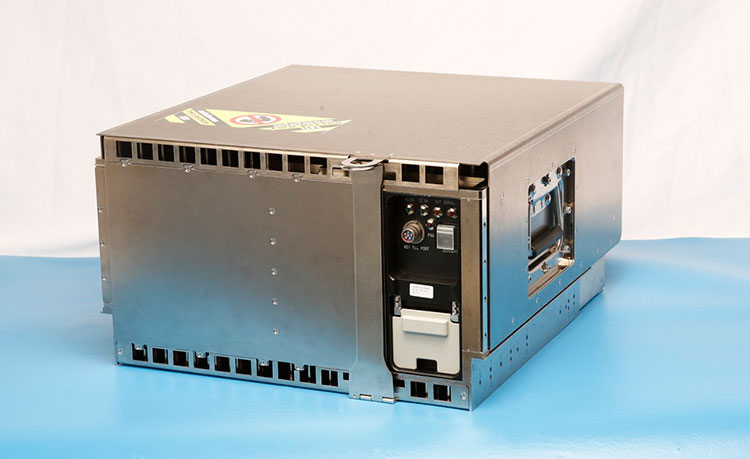
Harris Corporation delivered the first of 34 modernized receivers to support the GPS Next-Generation Operational Control System (OCX). They will receive the signals sent by the current GPS satellite constellation plus the new signals sent by the next generation GPS III — 13 military and civilian signals in all.
The receiver was shipped to the prime contractor, Raytheon Company, in Aurora, Colorado, after it passed a critical electromagnetic interference test, the first of many stringent qualification requirements. Though the receivers will be placed throughout the world, this first production unit will be installed in Aurora as OCX software development and integration continues.
OCX will replace the existing ground control system that receives signals from the 31 operational GPS satellites already orbiting Earth. Only OCX will be able to receive and decrypt all GPS III military and civil signals, however.
In addition to receivers, Harris has delivered 14 ground encryptors that will help protect the GPS signal. Harris also is providing critical software elements, which provide the fundamental navigation data to the GPS satellites and enable U.S. Air Force operators to better know and monitor the exact position and timing of the GPS constellation.
Risk Reduction Testing Completed for GPS OCX
Image: Raytheon
Raytheon reached a milestone in development of the GPS Next Generation Operational Control System (OCX), completing a series of Risk Reduction functional checkouts of OCX Block 1 capabilities, with a focus on OCX software.
This activity integrated iteration 1.5 of the OCX Block 1 Master Control Station with the GPS System Simulator and ran operational scenarios, representing the first end-to-end integration of available Block 1 capabilities.
The testing included GPS constellation management and sustainment, demonstrating OCX’s abilities for precision navigation and timing capabilities in a fully cyber-hardened environment.
The test also included running Kalman filters and generating GPS satellite navigation uploads. Future development will add to and expand capability to include both the civil and military modernized signals.
OCX’s development is delivered in “blocks,” with Block 0 comprising the Launch and Checkout System to take GPS III satellites into early orbit. Block 1 is built on Block 0 and delivers the full OCX capability, which allows the Air Force to transition from its current GPS ground controls to the modernized and secure GPS OCX master control station.
GPS OCX is being developed by Raytheon under contract to the U.S. Air Force Space and Missile Systems Center.
M-Code User Equipment Certified
L-3 Communications announced that its next-generation military code (M-code) GPS user equipment has successfully completed the final step in a government security certification process. L-3’s M-code GPS features advanced user equipment technology, increasing soldiers’ ability to resist enemy jamming and spoofing and performing significantly better in contested environments. The development and certification of this technology was performed under the Air Force Military GPS User Equipment (MGUE) program led by the GPS Directorate.
Certification review was performed by an independent government review team, with a focus on the security design of the L-3 GPS User Equipment. The goal of these new security standards is to further protect the integrity of the navigation and timing solutions and provide required safeguards for critical information inside GPS User Equipment.
Work on this project will be done by L-3 Interstate Electronics Corporation (L-3 IEC), which is part of the Precision Engagement and Training sector within L-3’s Electronic Systems business segment.
The first eight GPS III satellites are under contract and in production at Lockheed Martin’s GPS III Processing Facility outside of Denver.
GPS III Satellites 9 and 10 Procured, Launches Targeted for 2022
The U.S. Air Force Space and Missile Systems Center awarded a contract option to Lockheed Martin Space Systems Company to procure two additional GPS III satellites, space vehicles nine and 10 of the next generation. The contract option procures long lead and production hardware.
“The GPS III SV 9 and 10 satellites are expected to be ready for launch in 2022, thus sustaining the GPS constellation and the global utility the world has come to expect,” said Lt. Gen. Samuel Greaves, the Space and Missile Systems Center’s commander.
The Lockheed Martin team is finishing up final testing and integration activities on the first GPS III satellite, GPS III SV01, and is preparing to deliver it to the Air Force later this year. The second satellite, GPS III SV02, is poised to have its major functional systems fully integrated into one space vehicle prior to starting its own environmental testing. GPS III SV03 also is beginning to take form in the company’s production clean room as its major subcomponents are being assembled. All eight of the first set of GPS III satellites are in various stages of production at Lockheed Martin’s GPS III Processing Facility outside of Denver.
The government expects to compete future purchases of GPS III satellites, beginning with GPS III SV 11. This competition will maintain the current technical baseline of GPS III and will add additional hosted payloads to increase system accuracy, search-and-rescue capability, and universal S-band compatibility.
European GNSS Service Centre Opens
The European GNSS Agency (GSA) is gearing up to assume its operational role for Galileo in early 2017. This summer, the GSA formally accepted the Loyola de Palacio facility in Madrid, Spain, that houses the European GNSS Service Centre (GSC). This is a significant milestone in the development of the programme and its service provision as Galileo’s “door to the GNSS world.”
GSA already oversees the operation and service provision for the European Geostationary Navigation Overlay Service (EGNOS), along with managing the security accreditation and general security provision for both programmes.
The GSC offers 1,100 square metres of space and employs over 40 people. Since 2013, the core team at GSC has been providing limited services and working as a precursor to GSC v1. Its key work includes supporting the lead up to Galileo Initial Services provision, along with operating the GSC Helpdesk, disseminating orbital products to the search-and-rescue community, supporting GNSS-related research and industrial activity, and monitoring user satisfaction.
Once operational, GSC v1 will be connected to the Galileo core system, enabling the long-anticipated Commercial Service. This service is expected to enter operations by mid-2017.
SmartNet North America, a high-precision, high-availability network RTK correction service, is assuming operations and incorporating all of the Maine Technical Source (MTS) RTK Network into SmartNet. The merger brings professionals along the East Coast access to a broader coverage area, better geometry and optimized performance.
The MTS RTK Network has two national CORS base stations and 27 base stations covering most of New England. The incorporation of the MTS Network into SmartNet strengthens the network by giving users access to a range of additional tools, including full network quality monitoring and a comprehensive user portal with live status maps and rover management.
The MTS RTK Network has two national CORS base stations and 27 base stations covering most of New England.
Users will also be able to take advantage of immediate enhancements and investments SmartNet is currently making in the New England region. The network will continue to be supported by Maine Technical Source, the authorized sales and support organization for SmartNet solutions on the East Coast.
SmartNet North America is fully open to all makes and models of GNSS equipment and is designed to provide the highest reliability and accuracy 24/7. A variety of different subscription plans are available at the state, regional and national level for any application requiring precision GNSS corrections. The latest expansion brings the total number of SmartNet North America stations to over 1,200 in 40 states and 8 provinces, strengthening SmartNet’s position as the most extensive network coverage of any network service provider on the continent.
“Our commitment to excellence drives us to keep expanding to serve the needs of our customers,†said Wendy Watson, director of reference station operations — GNSS reference networks for SmartNet North America. “Whether it is through enriching our toolsets, adding new stations or incorporating existing networks with the assistance of valuable partners like Maine Technical Source, we will continue to make investments that provide users with the best possible service.”
“The MTS RTK Network was already built on reliable, high-performance Leica Geosystems GPS technology,†said Jim Bosworth of Maine Technical Source. “Now users will have the added benefit of being supported by the industry-leading SmartNet service. The incorporation of the MTS RTK Network into SmartNet is a logical next step in supporting our GPS and GNSS customers in the region.”
Out today, release 16.11 of Skydel Solutions’ SDX simulation software adds BeiDou to the list of constellations that SDX can simulate. Following release 16.7 in July, which added Galileo, the update makes SDX a multi-constellation, multi-frequency GNSS simulator.
Here are major improvements to the SDX simulator:
Added Galileo E1 (16.7)
Improvements to the Sky View and the display of multiple constellations (16.7)
Added Galileo E5a and E5b (16.11)
Added BeiDou B1 and B2 (16.11)
New Output configuration panel, replacing Modulation and allowing use of multiple radios (16.11)
GNSS simulation with four simultaneous constellations.
With the SDX, users can create a complete four-constellation dual-frequency simulation scenario on a single software-defined radio using only commercial-off-the-shelf hardware, Skydel said.
Talen-X has been given security approval by the GPS Directorate, allowing BroadSim to create and process Y-Code while in a classified environment.
BroadSim is a software-defined GNSS simulator that enables users to easily model true and spoofed signals. BroadSim was developed to simplify advanced jamming and spoofing scenarios with Navigation Warfare (NAVWAR) testing in mind.
BroadSim supports high dynamics, advanced jamming, spoofing and encrypted military codes.
Powered by Skydel’s SDX 1000-Hz software simulator engine, BroadSim can simulate multiple constellations including GPS, GLONASS, Galileo and BeiDou.
Software features:
Capable of generating and simulating multiple signal types
GPS L1, L2 with C/A, P, Y and M
GLONASS G1 and G2
Galileo E1 and E5
BeiDou B1 and B2
Intuitive control using Skydel’s SDX software
Utilizes four RF outputs, each with multiple simultaneous constellations
Generates high-fidelity jamming and interference signals
BroadSim hardware includes a generator and controller with two integrated commercial-off-the-shelf USRP radios, an integrated OctoClock-G with GPS disciplined oscillator, four frequency-independent transmit and receive channels and a UBX-160 RF daughterboard.
All four Galileo satellites are mated to the dispenser in readiness for the upcoming launch.
The launch campaign for the Nov. 17 Galileo launch from the French Guiana spaceport has entered its latest phase of preparations, with the mission’s four satellite passengers being installed on their multi-payload dispenser system.
The activity — performed in the Spaceport’s S3B clean room — clears the way for the satellites’ integration as a single unit atop the heavy-lift Ariane 5, which was transferred earlier this week from the Launcher Integration Building to the Final Assembly Building, where payload integration is set to occur, according to launch contractor Arianespace.
Designated Flight VA233, the upcoming mission is scheduled for a Nov.17 liftoff from the Spaceport in French Guiana at precisely 10:06:48 a.m. local time, with the four Galileo satellites subsequently being deployed into circular orbit during a mission lasting just under four hours.
Flight VA233 will mark Arianespace’s first use of Ariane 5 to loft spacecraft for Europe’s Galileo global navigation system, following seven previous missions with the medium-lift Soyuz — which carried a pair of satellites on each liftoff. Flight VA233 is scheduled as the company’s ninth launch overall performed so far in 2016, as well as the sixth this year using the heavy-lift workhorse. Arianespace’s full launcher family is rounded out by the light-lift Vega.
Two of the four Galileo satellites after their installation on the multi-passenger dispenser system, with a third positioned for its integration. (Photo: Arianespace)
Galileo is an important infrastructure program for Europe, creating a civil global satellite navigation system that provides highly accurate positioning with great precision and reliability.
It is funded and owned by the European Union, with overall responsibility for management and implementation held by the European Commission. Design and development of the new generation of systems and infrastructure has been assigned to the European Space Agency.
OHB System in Bremen, Germany, built the Galileo satellites, which are sized at 2.7 x 1.2 x 1.1 meters, while their navigation payloads were supplied by UK-based Surrey Satellite Technology.
NovAtel Inc. has placed a research contract to determine how GNSS technology can deliver a positioning solution that meets both the safety and accuracy requirements of unmanned automotive vehicles.
The research will include study concepts for high-precision, high-integrity carrier phase algorithms as well as threat models and safety monitors with the purpose of improving the safety of autonomous land transportation.
Syntony GNSS, a simulator company based in Toulouse, France, has landed a €1 million location infrastructure project for the underground metro in Stockholm, Sweden.
Stockholm’s metro stations are deep underground, dug under the sea in and around Stockholm. The metro lacked a system that would enable emergency 911 calls with associated essential localized position information to be carried from within the stations.
Syntony was able to provide a GPS-like signal infrastructure at the stations that is compatible with GPS-enabled smartphones. Instead of using Wi-Fi and Bluetooth, the system reproduces the GPS signal with transmitters, a signal recognizable by smartphones. With the system installed, emergency calls can be located in the underground. During its proof-of-concept tests, Syntony verified that there was no radiation of the signal outside any of the entrances to the test station — and therefore no GPS interference.
The system worked so well that Syntony was contracted in January to equip all 50 metro stations in Stockholm. Syntony is now is in talks with Singapore and is working to spread its system to the metros of other major cities worldwide.
Tests of the robustness of commercial GNSS devices against threats show that different receivers behave differently in the presence of the same threat vectors. A risk-assessment framework for PNT systems can gauge real-world threat vectors, then the most appropriate and cost-effective mitigation can be selected.
Vulnerabilities of GNSS positioning, navigation and timing are a consequence of the signals’ very low received power. These vulnerabilities include RF interference, atmospheric effects, jamming and spoofing. All cases should be tested for all GNSS equipment, not solely those whose applications or cargoes might draw criminal or terrorist attention, because jamming or spoofing directed at another target can still affect any receiver in the vicinity.
GNSS Jamming. Potential severe disruptions can be encountered by critical infrastructure in many scenarios, highlighting the need to understand the behavior of multiple systems that rely on positioning, and/or timing aspects of GNSS systems, when subject to real-world GNSS threat vectors.
GNSS Spoofing. This can no longer be regarded as difficult to conduct or requiring a high degree of expertise and GNSS knowledge. In 2015, two engineers with no expertise in GNSS found it easy to construct a low-cost signal emulator using commercial off-the-shelf software–defined radio and RF transmission equipment, successfully spoofing a car’s built-in GPS receiver, two well-known brands of smartphone and a drone so that it would fly in a restricted area.
In December 2015 the Department of Homeland Security revealed that drug traffickers have been attempting to spoof (as well as jam) border drones. This demonstrates that GNSS spoofing is now accessible enough that it should begin to be considered seriously as a valid attack vector in any GNSS vulnerability risk assessment.
More recently, the release of the Pokémon Go game triggered a rapid development of spoofing techniques. This has led to spoofing at the application layer: jailbreaking the smartphone and installing an application designed to feed faked location information to other applications. It has also led to the use of spoofers at the RF level (record and playback or “meaconing”) and even the use of a programmed SDR to generate replica GPS signals — and all of this was accomplished in a matter of weeks.
GNSS Segment Errors. Whilst not common, GNSS segment errors can create severe problems for users. Events affecting GLONASS during April 2014 are well known: corrupted ephemeris information was uploaded to the satellite vehicles and caused problems to many worldwide GLONASS users for almost 12 hours. Recently GPS was affected. On January 26, 2016, a glitch in the GPS ground software led to the wrong UTC correction value being broadcast. This bug started to cause problems when satellite SVN23 was withdrawn from service. A number of GPS satellites, while declaring themselves “healthy,” broadcast a wrong UTC correction parameter.
Atmospheric Effects. Single frequency PNT systems generally compensate for the normal behavior of the ionosphere through the implementation of a model such as the Klobuchar Ionospheric Model.
Space weather disturbs the ionosphere to an extent where the model no longer works and large pseudorange errors, which can affect position and timing, are generated. This typically happens when a severe solar storm causes the Total Electron Count (TEC) to increase to significantly higher than normal levels.
Dual-frequency GNSS receivers can provide much higher levels of mitigation against solar weather effects. However, this is not always the case; during scintillation events dual frequency diversity is more likely to only partially mitigate the effects of scintillation.
Solar weather events occur on an 11-year cycle; the sun has just peaked at solar maximum, so we will find solar activity decreasing to a minimum during the next 5 years of the cycle. However that does not mean that the effects of solar weather on PNT systems should be ignored for the next few years where safety or critical infrastructure systems are involved.
TEST FRAMEWORK
Characterization of receiver performance, to specific segments within the real world, can save either development time and cost or prevent poor performance in real deployments. Figure 1 shows the concept of a robust PNT test framework that uses real-world threat vectors to test GNSS-dependent systems and devices.
OPENING GRAPHIC
FIGURE 1. Robust PNT test framework architecture.
Figure 2. Detected interference waveforms at public event in Europe.
We have deployed detectors — some on a permanent basis, some temporary — and have collected extensive information on real-world RFI that affects GNSS receivers, systems and applications.
For example, all of the detected interference waveforms in Figure 2 have potential to cause unexpected behavior of any receiver that was picking up the repeated signal. A spectrogram is included with the first detected waveform for reference as it is quite an unusual looking waveform, which is most likely to have originated from a badly tuned, cheap jammer. The events in the figure, captured at the same European sports event, are thought to have been caused by a GPS repeater or a deliberate jammer. A repeater could be being used to rebroadcast GPS signals inside an enclosure to allow testing of a GPS system located indoors where it does not have a view of the sky.
The greatest problem with GPS repeaters is that the signal can “spill” outside of the test location and interfere with another receiver. This could cause the receiver to report the static position of the repeater, rather than its true position. The problem is how to reliably and repeatedly assess the resilience of GPS equipment to these kinds of interference waveforms. The key to this is the design of test cases, or scenarios, that are able to extract benchmark information from equipment. To complement the benchmarking test scenarios, it is also advisable to set up application specific scenarios to assess the likely impact of interference in specific environmental settings and use cases.
TEST METHODOLOGY
A benchmarking scenario was set up in the laboratory using a simulator to generate L1 GPS signals against some generic interference waveforms with the objective of developing a candidate benchmark scenario that could form part of a standard methodology for the assessment of receiver performance when subject to interference.
Considering the requirements for a benchmark test, it was decided to implement a scenario where a GPS receiver tracking GPS L1 signals is moved slowly toward a fixed interference source as shown in Figure 3.
The simulation is first run for 60 seconds with the “vehicle” static, and the receiver is cold started at the same time to let the receiver initialise properly. The static position is 1000m south of where the jammer will be. At t = 60s the “vehicle” starts driving due north at 5 m/s. At the same time a jamming source is turned on, located at 0.00 N 0.00 E. The “vehicle” drives straight through the jamming source, and then continues 1000m north of 0.00N 0.00E, for a total distance covered of 2000m. This method is used for all tests except the interference type comparison where there is no initialization period, the vehicle starts moving north as the receiver is turned on.
The advantages of this simple and very repeatable scenario are that it shows how close a receiver could approach a fixed jammer without any ill effects, and measures the receiver’s recovery time after it has passed the interference source. We have anonymized the receivers used in the study, but they are representative user receivers that are in wide use today across a variety of applications. Isotropic antenna patterns were used for receivers and jammers in the test. The test system automatically models the power level changes as the vehicle moves relative to the jammer, based on a free-space path loss model.
RESULTS
Figure 4 shows a comparison of GPS receiver accuracy performance when subject to L1 CHIRP interference. This is representative of many PPD (personal protection device)-type jammers.
Figure 5 shows the relative performance of Receiver A when subject to different jammer types — in this case AM, coherent CW and swept CW.
Finally in Figure 6 the accuracy performance of Receiver A is tested to examine the change that a 10dB increase in signal power could make to the behavior of the receiver against jamming — a swept CW signal was used in this instance.
Figure 4. Comparison of receiver accuracy when subject to CHIRP interference.
Figure 5. Receiver A accuracy performance against different interference types.
Figure 6. Comparison of Receiver A accuracy performance with 10db change in jammer power level.
Discussion. In the first set of results (the comparison of receivers against L1 CHIRP interference), it is interesting to note that all receivers tested lost lock at a very similar distance away from this particular interference source but all exhibited different recovery performance.
The second test focused on the performance of Receiver A against various types of jammers — the aim of this experiment was to determine how much the receiver response against interference could be expected to vary with jammer type. It can be seen that for Receiver A there were marked differences in response to jammer type. Finally, the third test concentrated on determining how much a 10dB alteration in jammer power might change receiver responses. Receiver A was used again and a swept CW signal was used as the interferer. It can be seen that the increase of 10dB in the signal power does have the noticeable effect one would expect to see on the receiver response in this scenario with this receiver.
Having developed a benchmark test bed for the evaluation of GNSS interference on receiver behavior, there is a great deal of opportunity to conduct further experimental work to assess the behavior of GNSS receivers subject to interference. Examples of areas for further work include:
Evaluation of other performance metrics important for assessing resilience to interference
Automation of test scenarios used for benchmarking
Evaluation of the effectiveness of different mitigation approaches, including improved antenna performance, RAIM, multi-frequency, multi-constellation
Performance of systems that include GNSS plus augmentation systems such as intertial, SBAS, GBAS
CONCLUSIONS
A simple candidate benchmark test for assessing receiver accuracy when subjected to RF interference has been presented by the authors.
Different receivers perform quite differently when subjected to the same GNSS + RFI test conditions. Understanding how a receiver performs, and how this performance affects the PNT system or application performance, is an important element in system design and should be considered as part of a GNSS robustness risk assessment.
Other GNSS threats are also important to consider: solar weather, scintillation, spoofing and segment errors.
One of the biggest advantages of the automated test bench set-up used here is that it allows a system or device response to be tested against a wide range of of real world GNSS threats in a matter of hours, whereas previously it could have taken many weeks or months (or not even been possible) to test against such a wide range of threats.
Whilst there is (rightly) a lot of material in which the potential impacts of GNSS threat vectors are debated, it should also be remembered that there are many mitigation actions that can be taken today which enable protection against current and some predictable future scenarios.
Carrying out risk assessments including testing against the latest real-world threat baseline is the first vital step towards improving the security of GNSS dependent systems and devices.
ACKNOWLEDGMENTS
The authors would like to thank all of the staff at Spirent Communications, Nottingham Scientific Ltd and Qascom who have contributed to this paper. In particular, thanks are due to Kimon Voutsis and Joshua Stubbs from Spirent’s Professional Services team for their expert contributions to the interference benchmark tests.
MANUFACTURERS
The benchmarking scenario described here was set up in the laboratory using a Spirent GSS6700 GNSS simulator.
An antenna upgrade for U.S. Navy submarines is being provided to improve GPS anti-jamming capabilities.
Mayflower Communications Company, subcontractor to Lockheed Martin Sippican, is applying its Submarine Anti-Jam GPS Enhancement (SAGE) capability to the U.S. Navy Multifunction Mast Antenna System (OE-538B) upgrade to improve submarine communications and meet Navigation Warfare (NAVWAR) requirements.
The SAGE (NavGuard 501) GPS anti-jam unit.
The Mayflower SAGE — a variant of Small Antenna System (SAS) — was developed specifically for inclusion on Submarine Platforms to support U.S. Navy requirements for GPS anti-jam.
The SAGE’s small size and feature set make it capable for ease of integration by Lockheed Martin Sippican into the OE-538B antenna mast.
The SAGE is a high performance and low size, weight and power (SWaP) cost-effective antenna system that will enable the U.S. Navy submarine fleet to operate in GPS contested or denied (NAVWAR) environments.
The SAGE (NavGuard 501) can supply clean GPS Signals to multiple GPS receivers from a single antenna and is compatible with C/A, SAASM P(Y), and M-code receivers. The SAGE fits he small SWaP requirements of the OE-538B antenna mast.
The SAGE is Mayflower’s latest federated, affordable anti-jam solution that leverages proven small antenna system (SAS) technology and provides Iridium capability in an integrated antenna. The SAS solution has been extensively tested by the federal government on multiple platforms.
The SAGE is the highest performance and smallest GPS anti-jam federated solution with Iridium capability in the market. The SAGE AJ solution offers an affordable SWaP-C alternative over larger and more expensive existing anti-jam systems.
The Space and Naval Warfare Systems Command (SPAWAR HQ) awarded the sole source contract for the development of an OE-538B antenna upgrade and procurement to Lockheed Martin Sippican/Granite State Manufacturing Submarine Antenna Joint Venture. The contract is in support of the Program Executive Office for Command, Control, Communications, Computers, and Intelligence (PEO C4I), Undersea Integration Program Office (PMW/A 770).
Mayflower was selected by the U.S. Navy and Lockheed Martin Sippican to design, develop, and integrate the Submarine Anti-Jam GPS Enhancement (SAGE) (NavGuard 501) product.
Joseph Thomas, Mayflower’s Director of Government Programs, said, “The SAGE product has given Mayflower the opportunity to support a U.S. Navy National Strategic Level Platform and to expand into the next generation of small SWaP NAVWAR GPS Anti-Jam systems. The SAGE ensures we can continue to offer the warfighters the very latest and most efficient technology to support operations in an A2AD Environment”.
Mayflower is working closely with Lockheed Martin Sippican to complete integration and environmental qualification of the SAGE to support the OE-538B program requirements.
Spoofing as it applies to GPS is an attempt to deceive a GPS receiver by broadcasting signals that the receiver will use instead of the live sky signals.
Spoofing is different from jamming. Jamming is easier for a receiver to detect, and while it can disrupt the receiver, it cannot relocate it. Spoofing can be used as an attack on systems that use GPS for navigation, or even for precise time transfer, to misguide a valuable asset for malicious intent.
We all would like to think that receivers should always indicate when something out of the ordinary is happening such as what would happen during a spoofing attack, but if the overall system using the receiver does not monitor or attempt to use any available indications, a spoofing attack may go undetected.
Understanding how a GPS application will respond in a spoofing attack is the key to detecting and mitigating the effects of spoofing. For example, it could be assumed by a navigation system designer that using multiple GNSS systems will prevent a spoofing attack consisting of only GPS. But how do you know, and before a potentially catastrophic event?
The Vulnerability Test System.
Vulnerability Test System
A vulnerability test system (VTS) can be used to understand how a system using a GPS receiver, and the overall system integration, will react to spoofing in order to develop mitigation techniques and countermeasures.
Understanding the behavior of the receiver when faced with a spoofing attack is key to hardening applications for resilient position, navigation and timing (PNT). Spectracom has developed a GPS/GNSS VTS, based on its GNSS RF simulator platform, to help understand the effects of intentional disruption of GPS signals.
In the case of a GPS spoofing scenario, the VTS allows full control over the synchronization between the spoofer and “virtual live sky,” their power levels and position variation in a completely closed system that won’t interfere with actual GNSS signals. The VTS consists of two GPS simulators, one simulating live sky and one representing the attempt of the spoofer. It also uses a synchronization unit, an RF combiner and a PC controller.
Architecture of the VTS.
Critical Test Parameters
Several parameters can be varied in the test system to help understand how vulnerable a specific receiver system is to a spoofing threat. Each of the most critical parameters — time, position and power level — can be manipulated independently, allowing the design of a comprehensive test plan.
Time. The timing accuracy of the spoofing signals to the live signals is the first critical parameter. Utilizing separate outputs from the VTS synchronization unit, the on-time point between the GPS RF generation can be varied. Two pulse-per-second signals are used as triggers to the GPS simulators, therefore creating the offset in time between the two RF signals. This offset is controllable to the nanosecond. Another time-related parameter to consider is the capture time — how long the spoofing signal is applied before attempting to redirect the receiver.
Position. We expect that for spoofing to be successful, the GPS position generated by the spoofer must be accurate to that of the receiver to be spoofed. But exactly how close does the spoofer need to be relative to the receiver’s position? The effect of position in the spoofing scenario is a parameter that can be adjusted to understand the extent of the vulnerability to spoofing.
Using two simulators instead of spoofing live sky makes it much easier to design and execute various test cases to understand the receiver’s susceptibility. The tests can be performed under varying motion trajectories of the receiver under test. For example, we can test if or when the spoofer can anticipate motion or changes in direction. Practically, spoofers are required to be positionally accurate to successfully take control over a receiver, which means spoofing is even harder when in motion.
But to what extent? Testing is the only way to answer the question.
Critical parameters for testing vulnerabilities to spoofing.
Power. The spoofing signal needs to be slightly greater than the live signal to capture the receiver. The test system allows full control of the power levels to determine how much greater the power should be. Too much power will jam the receiver. The test system can determine if there are any indicators given by the receiver when a signal only a few decibels higher than the transmitted signal is received.
Testing Multi-GNSS
Adding multi-GNSS constellations to the GPS application is a valuable tool in hardening systems. The VTS can test GPS with various combinations of other GNSS systems (GPS, QZSS, BeiDou, Galileo, GLONASS) to understand if multi-GNSS is an effective method to overcome spoofing attacks. As attackers get more sophisticated, spoofing will probably not be limited to GPS.
Many other signals and references have been used as a complement to GPS in navigation applications. It is expected that these can also be used to harden receiver systems. However, the complexities of these systems can be difficult to test in a laboratory. For those with the proper safeguards and approvals to emit GPS-like signals in a test-range setting, the VTS can add features to synchronize to live sky and accept input from a vehicle-detection and tracking system.
In the United States, the consideration of such testing would only occur after significant coordination between the Department of Defense, the Coast Guard, the Federal Communications Commission, the Federal Aviation Administration, and others.
Conclusion
A GNSS VTS allows for comprehensive characterization through systematic, repeatable tests of receiver performance in the presence of a spoofer. By designing detection and mitigation actions into a navigation application, it may be possible to identify and even overcome risks of a spoofing attack.
Monitoring loss of lock, receiver noise, using an inertial navigation system, and estimated position error are possible parameters to observe, but each receiver may report different indications. More test cases can be created and performed using a VTS to fully characterize a receiver and how it will respond to a spoofing attack.
By Karen Parrish, DoD News, Defense Media Activity
An Air Force program that will provide a vital new command system for the global positioning system satellite constellation in the shortest time possible will continue despite cost growth, Defense Department officials have confirmed.
Frank Kendall, undersecretary of defense for acquisition, technology and logistics, announced Oct. 12 the continuation of an over-cost program supporting the global positioning system. Here, Kendall is briefed by Jose Romero-Mariona on cybersecurity science and technology during Kendall’s visit to Space and Naval Warfare Systems Center Pacific in San Diego, Aug. 24. (Navy photo by Aaron Lebsack)
The next-generation operational control system, known as OCX, reached what is called a Nunn-McCurdy breach on June 30. The Nunn-McCurdy provision applies to weapons programs and requires the military services to notify Congress if a program’s cost per unit increases 25 percent or more over the current baseline estimate.
But well before June 30, defense acquisition experts began working with Raytheon, the contractor for OCX, to resolve program issues. In December 2015, Undersecretary of Defense for Acquisition, Technology and Logistics Frank Kendall directed in-depth quarterly reviews, including a series of “deep dives” overseen by him. Certification activities began in July 2016, and culminated with Kendall certifying the program to Congress yesterday, thus allowing the program to continue.
Next-Generation GPS
James MacStravic, acting assistant secretary of defense for acquisition, discussed OCX and its importance with DoD News.
“This is what the controllers on the ground are going to use to make sure that all the satellites are talking to each other, that they’re exchanging the same information [and] that they’re where they’re supposed to be,” he said.
The OCX system will command all modernized and legacy GPS satellites, manage all civil and military navigation signals and provide improved cybersecurity and resilience for the next generation of GPS operations.
The OCX program includes the following phases: Block 0, to perform launch and checkout of GPS-III satellites; Block 1, to command all navigation signals, including the modernized military signal; and Block 2, for additional enhancements to signal assurance and navigation warfare capabilities. The ground segment capability not only supports military forces, but also civil, commercial and scientific uses. The current total program cost estimate for OCX is $5.46 billion.
OCX will consist of:
A master control station and alternate master control station;
Dedicated monitor stations;
Ground antennas;
GPS system simulator; and
Standardized space trainer
Turning the Program Around
Defense officials said factors in the OCX cost growth included late recognition of the magnitude of information assurance work that was required, concurrent systems engineering that drove significant rework, inconsistent configuration management of the program baselines, immature software and a lack of automation across the program. These issues drove schedule slips, which in turn increased the cost of the program, leading to the breach.
MacStravic described the efforts defense officials and Raytheon have made to turn the program around. He emphasized the work has included the personal involvement of Kendall, Air Force Secretary Deborah Lee James and Raytheon’s chief executive officer.
“What we spent the summer doing was making sure … does this program have the right management resources, the right financial resources and an appropriate schedule to succeed?” MacStravic said.
Officials report that after three on-site quarterly reviews, Kendall’s assessment is that Raytheon is making substantial progress on the program, but that some additional schedule increase has occurred and that there is risk of more schedule increases.
Progress has been sufficient to support certification under the Nunn-McCurdy process, officials said. Kendall’s office will continue the OCX quarterly reviews begun in March 2016, which to date have included the secretary and principal deputy acquisition chief of the Air Force, the program executive officer and Raytheon’s chief executive officer.
The alternatives to certifying the program included several options, including program termination, but this was deemed simply unworkable, due to the extended time it would require to design and field a new ground system for the vital GPS III network.
According to officials, the future of the OCX program will depend upon Raytheon’s ability to demonstrate that it can deliver the needed capability to the Air Force at acceptable cost and within an acceptable time.