The Coast Guard Navigation Center has published a special notice to mariners that use GPS equipment. The special notice outlines the details of the GPS Week Number Rollover that will occur April 6-7.
To best prepare for the rollover event, users of GPS equipment who are concerned should update their firmware, or contact their equipment manufacturer to ensure their equipment is ready for this event.
When the week number reaches 1024 at 18 seconds before midnight (UTC) on April 6, it will reset to zero as it keeps counting. This has happened once before, in August 1999.
Recent devices have likely been designed to handle the rollover event.
Older GPS receivers, however, or receivers that have not been provided manufacturer updates, may be affected by the rollover. The impact might occur in April, or could affect such equipment at a later date. The date might revert back to August 1999, or may revert to another date. Since this issue does not affect the other parts of the GPS navigation message (it only affects the date), the receiver’s ability to calculate the position and to display the exact time of day should not be impacted.
Additional information about GPS and the GPS Week Number Rollover is available here:
Civil GPS users are encouraged to report disruptions or anomalies to the U.S. Coast Guard Navigation Center or via phone at 703-313-5900, 24 hours a day.
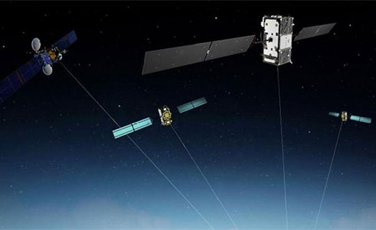
Following a waiver by the U.S. Federal Communications Commission (FCC) of its rules in November 2018, in which it allowed devices in the United States to access signals transmitted by the Galileo Global Navigation System, leading U.S. manufacturers are preparing to roll-out Galileo on U.S. territory.
At a meeting on Nov. 15 last year, the US FCC granted in part a request from the European Commission for a waiver of the FCC rules so that devices in the United States may access specific signals transmitted by Galileo.
This decision means that consumers and industry in the U.S. are now able to access certain satellite signals from the Galileo system, which can be used in combination with the U.S. Global Positioning System (GPS). The improved availability, reliability, and resiliency offered by incorporating Galileo capability into devices is something that U.S. chip manufacturers are eager to pass on to their customers.
“This is an important market development opportunity for manufacturers in the U.S. The FCC ruling means that industry can now benefit from the use of Galileo signals. The added accuracy and robustness offered by multi-constellation and multi-frequency capability will be a key differentiator on the market,” said Carlo des Dorides, Executive Director of the European GNSS Agency (GSA).
“We are glad to see FCC supporting Broadcom’s dual frequency GNSS vision, for which the GPS and Galileo combination is key,” said Vijay Nagarajan, VP Marketing Wireless Connectivity and Communication Division at Broadcom. “We enabled the world’s first dual frequency GNSS phone in 2018 with the simple goal of providing accurate location to the consumer even amidst the skyscrapers in a busy downtown. We are certain that consumers will benefit from this FCC ruling that will further drive the adoption of dual frequency GNSS.”
“As a leader in developing cellular technology — today, as the world launches 5G and dating back to Qualcomm’s legacy in 4G, 3G and 2G — including work to incorporate robust navigation solutions for smartphones, Qualcomm Technologies integrated Galileo across its chipset portfolio because we understand the importance and benefits of accurate, reliable, and rapid position location for consumers,” said Dean Brenner, senior vice president of Spectrum Strategy and Tech Policy, Qualcomm Incorporated. “We’re excited about the FCC allowing access to Galileo signals in the U.S. for commercial Location Based Services because it is a big step forward in improving the user experience, particularly in dense urban environments.”
Activating Galileo in the U.S.
Both Broadcom and Qualcomm Technologies, Inc. already have dual-frequency solutions that support Galileo E1/E5a signals: the world’s first dual frequency GNSS smartphone, the Xiaomi Mi-8, was fitted with a Broadcom BCM47755 chip and, in December, Qualcomm Technologies launched the newest generation in its 8 Mobile Platform Series, the dual-frequency Qualcomm Snapdragon 855 Mobile Platform.
“Approximately 100 smartphone models are already fitted with chipsets from these two manufacturers. Following the FCC ruling, we are expecting to see a significant increase in Galileo users coming from the U.S.,” said Justyna Redelkiewicz Musial, in charge of LBS and IoT market development at the GSA.
Better positioning and navigation
The FCC ruling permits access to two Galileo signals — the E1 signal that is transmitted in the 1559-1591 MHz portion of the 1559-1610 MHz Radio-navigation-Satellite Service (RNSS) frequency band and the E5 signal that is transmitted in the 1164-1219 MHz portion of the 1164-1215 MHz and 1215-1240 MHz RNSS bands.
Access to multi-constellation and multi-frequency capability means that users in the U.S. will be able to benefit from a better positioning and navigation experience particularly in urban environments where the unique shape of the E5/L5 signal makes it easier to distinguish real signals from the ones reflected by buildings, reducing the multipath effect. The simultaneous use of E5/L5 frequencies also mitigates other sources of error, such as ionospheric distortions, and makes the signal more robust against interference and jamming.
A self-driving tractor using the BeiDou Navigation Satellite System (BDS) was tested successfully March 10 in northwestern Tunisia, according to China.org.cn.
The representatives of China-Arab BDS/GNSS center and the Arab Information and Communication Technologies Organization (AICTO), as well as the academic staff of an engineering school in Mjez El-Beb region in northwestern Tunisia, attended the test ceremony.
The smart tractor, used in various agricultural activities, was equipped with a BDS receiver so that it could be controlled remotely without a driver.
“I am very impressed and surprised by the quality of the equipment offered by BeiDou,” said Sami Trimech, the strategic planning and development director at AICTO.
“We had a dream to bring BeiDou to the Arab countries,” said Nour Laabidi, the project manager at AICTO and head of China-Arab BDS/GNSS center in Tunisia.
“This is a pilot project. We are happy to implement it in our country and I hope that all Arab countries will be able to use this Chinese technology,” Laabidi said.
Hassan Kherroubi, a specialist in the mechanical industry at the Mjez El-Beb engineering school, stressed the contribution of this Chinese technology to the agricultural sector in Tunisia.
Agricultural activities, including harvest, will be more profitable and more effective with such technologies, according to Kherroubi.
“Our main concern is to benefit all Arab and African countries of this fruitful cooperation between Tunisia and China,” Kherroubi said, adding that this advanced technology will bring a bright future to the region.
BDS is compatible with other navigation systems, such as GPS, and users can receive services from both systems at the same time, improving positioning accuracy.
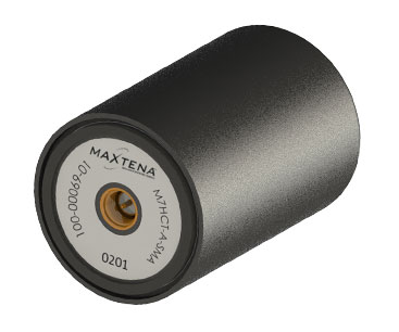
Maxtena Inc. has introduced a patented GNSS antenna designed for high-precision and autonomous multi-frequency applications. The M7HCT-A-SMA antenna is a high-accuracy, multi-frequency active quadrifilar helix GNSS antenna.
Photo: Maxtena
Maxtena is a U.S.-based antenna design and manufacturing company and inventor of the patented Dynamic Aperture Technology.
The new design will offer concurrent GNSS reception on L1: GPS, GLONASS, Galileo, Beidou and L2: GPS L2C, Galileo E5B and GLONASS L3OC in a rugged, compact and ultra lightweight form factor.
The antenna is designed for GIS, RTK and other high-accuracy GNSS applications such as the drone and automotive markets, where high performance and low weight are driving features in antenna selection.
The M7HCT-A-SMA active helix design features Maxtena’s patented compact and lightweight Helicore technology. This technology provides exceptional pattern control, polarization purity and high efficiency in a very compact form factor.
The antenna offers up to 30-dB gain for GNSS applications that utilize GPS, GLONASS, Galileo and Beidou, in one radome housing with a single SMA connector.
The M7HCT-A-SMA will join Maxtena’s line of rugged GNSS helix antennas that are ultra lightweight, small, and precise. The M7HCT-A-SMA weighs 25 grams and is housed in automotive grade PCB plastic with automotive grade electronics and is rated IP67 when mounted.
It is ground plane independent and offers extremely low power consumption and minimal phase-center variation over azimuth. The antenna offers superb axial ratio ensuring multipath error is mitigated.
“Maxtena is very excited to be launching a game-changing antenna for the UAV, drone, and automotive markets, and really for any application requiring a high performance, lightweight antenna that can cover so many frequencies. It is the most robust antenna solution on the market,” said Maxtena Vice President of Sales and Marketing Vanja Maric.
As a risk reduction effort for the U.S. Air Force’s GPS III Follow On (GPS IIIF) satellite program, Frequency Electronics Inc. has received a contract from Lockheed Martin Space, valued at $5.9 million, for the qualification of FEI’s Digital Rubidium Atomic Frequency Standard (DRAFS).
The contract’s intent is to qualify FEI’s DRAFS for potential use on the new GPS IIIF satellites, securing the industrial base for high-accuracy GPS atomic clocks.
To help the Air Force modernize its GPS satellite constellation with new technology and capabilities, Lockheed Martin Space designed and built the most powerful GPS satellite, GPS III. With 10 satellites under contract, in 2018, the Air Force selected Lockheed Martin to build up to 22 additional GPS IIIF satellites, adding new features and resiliency to the flexible satellite design. The Air Force began launching GPS III satellites in December 2018. Today, more than 4 billion users rely on GPS.
“We are extremely pleased to be awarded this contract and the opportunity to play a significant role in the GPS IIIF program,” Stanton Sloane, FEI’s CEO commented. “This award is the culmination of 50+ years of research and development of advanced quartz and atomic clocks based on FEI’s proprietary technologies. We are also pleased to continue our long-standing relationship with Lockheed Martin Space on critical national security programs.”
Martin Bloch, FEI’s Executive Chairman added, “I congratulate the FEI team on the development of this digital Rubidium clock for GPS IIIF program. FEI will continue the development of advanced clock technologies for future generations of Satellites and Terrestrial applications.”
Frequency Electronics designs, develops and manufactures high-precision timing, frequency control and synchronization products for space and terrestrial applications. Its products are used in satellite payloads and in other commercial, government and military systems including C4ISR and EW markets, missiles, UAVs, aircraft, GPS, secure radios, energy exploration and wireline and wireless communication networks.
Its subsidiaries and affiliates include FEI-Zyfer, which provides GPS and secure timing (“SAASM”) capabilities for critical military and commercial applications; and FEI-Elcom Tech, which provides subsystems for the Electronic Warfare markets and added resources for RF microwave products.
Norway has electronic proof that Russian forces disrupted GPS signals during recent NATO war games, according to a report in Reuters news service.
The Scandinavian country and North Atlantic Treaty Organization (NATO) member has demanded an explanation from its neighbor. “We recognize Russia’s right to exercise and train its capacities [but] it is not acceptable that this kind of activity affects security in Norwegian air space,” stated the Norwegian defense ministry.
Finland and Norway published claims in November that Russia may have intentionally disrupted GPS signals before and during NATO military exercises. The radio-frequency interference also affected the navigation of civilian air traffic in the Arctic. Both countries protested to Russia, which dismissed the allegations.
“We gave them the proof,” Norwegian Defence Minister Frank Bakke-Jensen stated publicly. Russia demurred, with Foreign Minister Sergey Lavrov terming the Norwegian allegations “a fantasy,” and said it would conducts its own investigation. “To be a neighbor of Russia you need to be patient,” added Bakke-Jensen.
Could Russia have targeted Norway intentionally? The minister replied: “They were exercising very close to the border and they knew this will affect areas on the other side.”
November saw NATO’s largest exercise in decades, involving forces from 31 countries in an area stretching from the Baltic Sea to Iceland.
Above: Krasukha jammer mounted on a heavy-duty truck, part of the radio electronic warfare unit (EW) of the Western Military District. (Photo: Ministry of Defense of the Russian Federation)
A series of documentary videos on automation and technology in the construction and agriculture industries covers drone inspection of infrastructure among other new trends. Filmed in the U.S., the Netherlands, United Kingdom, and Germany, the series of brief films produced by Topcon Positioning Group emphasizes how technological advancements have changed infrastructure — how it is designed, built and maintained — and what to expect going forward.
“The infrastructure industry is changing quickly, and this video series highlights how this advancement is part of a larger story of technology changing the paradigm everywhere. To stay on top, businesses will need to adopt automation and new technology,” according to Topcon spokesperson Jackie Ferreira.
A spokesperson from Intel describes how drone inspection facilitated data gathering and project planning for a complex restoration project on the Great Wall of China, in an area with very difficult access.
NovAtel’s Waypoint Products Group has released version 8.80 of its GNSS and GNSS+INS post-processing software products, including Inertial Explorer, Inertial Explorer Xpress, GrafNav and GrafNet. All Waypoint customers with an active subscription that are within the support period qualify for the Waypoint 8.80 upgrade at no additional charge.
Key features of the 8.80 release include:
High-rate precise satellite orbit and clock corrections available in minutes with the TerraStar-NRT option
Increased accuracy for pedestrian and vehicle applications by applying vehicle constraints using our SPAN intelligent vehicle dynamics modelling
Ability to use L5, E5a, B3 in differential solutions
14 percent faster processing with 64-bit support
For applications requiring highly accurate post-mission position, velocity or attitude, post-processing maximizes the accuracy of the solution by processing previously stored GNSS and inertial measurement unit (IMU) data forward and reverse in time, and combining the results. The position, velocity and attitude solution can be smoothed and output at the required data rate and in the coordinate frame required. This process also provides the ability to assess the solution reliability and accuracy.
The GrafNav and Inertial Explorer software packages are available as a digitally secured machine-portable license. The products are also available as a perpetual license or as a time-limited term license. A Software Development Kit (SDK) is available to allow developers to customize the entire processing workflow to suit their customers or application.
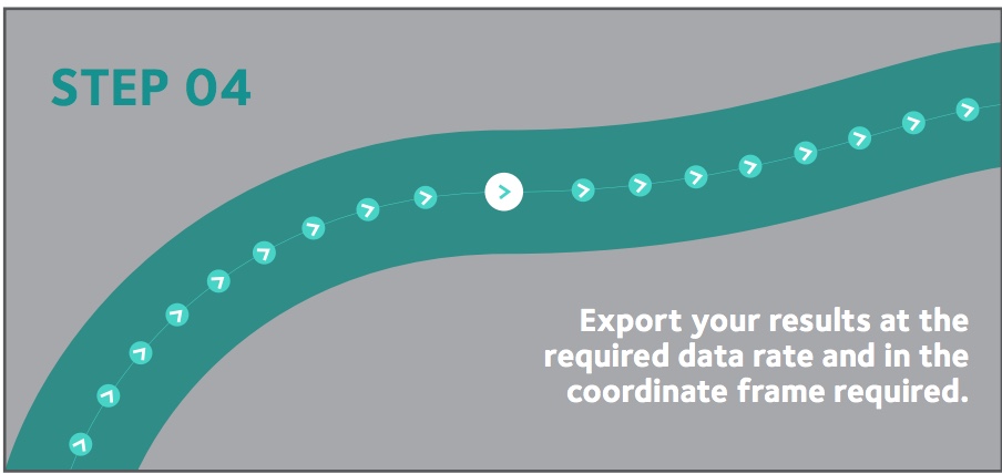
The Waypoint process:
Step 1: Capture raw GNSS and IMU data.
Step 2: Waypoint post-processing software maximizes the accuracy of the solution by independently processing data forward and reverse in time and combining the results.
Step 3: The position, velocity and attitude solution is smoothed to deliver an unparalleled level of accuracy. In-depth quality analysis tools verify the quality of the trajectory.
Step 4: Export your results at the required data rate and in the coordinate frame required.
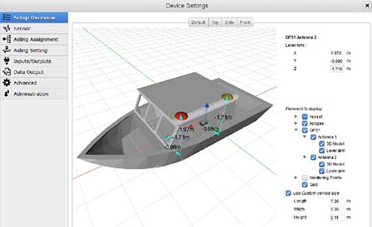
The Horizon fiberoptic gyro (FOG) inertial measurement unit (IMU) now forms part of SBG Systems’ Navsight Marine Solution, dedicated to hydrographers. Navsight is available at different levels of accuracy to meet the various application requirements and can be connected to various external equipment such as echo-sounders, lidar, and so on.
Photo: SBG Systems
Navsight Marine Solution already offered two levels of performance with the Ekinox and Apogee IMUs. These MEMS-based IMUs address most of hydrographics markets whether shallow or deep water.
The new Horizon IMU enables customers to deploy Navsight in the most demanding environments such as surveying highly dense areas (bridges, buildings, and so on) as well as applications where only a single antenna can be used.
The Horizon IMU is based on a closed-loop FOG technology which enables ultra-low bias and noise levels. This technology allows robust and consistent performance even in low dynamics survey.
Navsight solution is easy to install, as the sensor alignment and lever arms are automatically estimated and validated. Once connected to the Navsight processing unit, the web interface guides the user to configure the solution. A 3D view of the vessel shows the entered parameters so that the user can check the installation. The Navsight unit also integrates light emitting diode (LED) indicators for satellite availability, RTK corrections, and power. It comes with a rugged enclosure, or in a rack version for larger vessels.
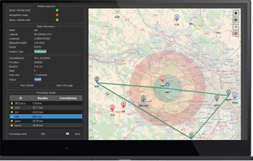
Completing the Navsight offer, Qinertia, SBG’s post-processing software, gives access to offline RTK corrections from more than 7,000 base stations located in 164 countries. Trajectory and orientation are then greatly improved by processing inertial data and raw GNSS observables in forward and backward directions. Computation takes less than 3 minutes for a 6-hour log thanks to the Forward and Backward calculation processed at the same time.
Check out a Nearmap high-resolution aerial image of Zions Bank Stadium/Real Academy. The solar was installed by Auric Solar. (Photo: Nearmap)
High-resolution aerial maps from NearMap are helping Auric Solar, a residential and commercial solar power provider, accelerate its initial site assessments, develop a more complete and accurate view of properties, and create winning proposals.
Auric accesses Nearmap imagery through the Aurora Solar platform, a solar sales and design software program. By utilizing Aurora software integrated with Nearmap imagery, Auric analysts have access to clear and current imagery. Headquartered in Salt Lake City, Utah, Auric services all of Utah, Idaho, Colorado and Oregon.
“Aurora’s responsive engineering interface coupled with Nearmap’s high-resolution captures allow us to use a combination of 3-D lidar models and 2-D high-resolution maps for complete accuracy in the planning and measuring stage of a project. This equips both the sales and analytics teams with accurate information to save time, money and serve the customer,” said Tyler Soukup, director of analytics at Auric Solar.
Analysts can make accurate measurements, run production numbers, identify roof obstructions and craft proposals all within the program. The sales team, analysts and installers are all on the same page, significantly reducing change orders.
The absolute horizontal accuracy of Nearmap’s georeferenced imagery is 0.75m (RMSE) or better. Measurements taken with Nearmap measurement tools are accurate to within 15cm for an individual photo. The company’s HyperCamera aerial photography system captures overlapping photographs along a flight path covering a survey area. Each photograph is tagged with its GPS location. Proprietary HyperVision technology then triangulates, orthorectifies and stitches these GPS-tagged photographs into a georeferenced photomap with an absolute horizontal accuracy of 0.75m (RMSE) and relative accuracy of 15cm. The process employs a combination of GPS positioning, high photo redundancy and triangulation of ground features to ensure this level of accuracy without the use of ground control points.
Solar panel installer Auric also has access to Nearmap historical imagery from years past, including leaf-on and leaf-off imagery, which presents the presence or lack of the foliage depending on the season. This greatly enhances shading analysis, making it easier to place the panels for maximum sun exposure. The company not only saves a significant amount of time with fewer onsite visits to qualify homes, but it also opens up more customers to solar.
“We’ve been able to qualify more customers than ever because of Nearmap’s clear, current captures. You really can’t accurately qualify a property without up-to-date imagery,” notes Soukup. “We quote projects from $20,000 to a few million dollars, and our proposals, plans and marketing materials should match that level of value. Nearmap helps us create a ‘wow’ factor.”
Before using Nearmap aerial imagery, Auric used using low-resolution satellite imagery to qualify properties. With outdated, blurry imagery, it was difficult to make accurate measurements and qualify a home before sending a technician for an on-site assessment.
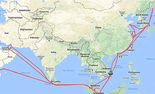
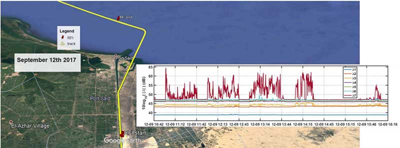
A year-long project aboard a commercial cargo ship collected tens of thousands of snapshots of radio-frequency interference in the GNSS band on a passage from Spain to Korea and back. Most interference was detected in busy port areas, less interference while transiting along coasts, and while least frequent, interference was still found in the open ocean.
Researchers at the German Aerospace Center (DLR) are still analyzing the vast amount of GNSS disruption data collected during the year-long project. Two papers have already been published about this project, and more are on the way, according to principle researcher Emilio Pérez Marcos.
In a paper presented at the Institute of Navigation last year, Marcos and his co-authors outlined the results of the last five months of this unique sampling experiment. Detection equipment was mounted on a large Hapag-Lloyd container ship. The antenna was mounted about 50 meters above the water line and provided a line-of-sight of 25km or more. The L1/E1 and L5/E5a frequency bands were continuously monitored. In addition to a “Snapshot” recording device used to save raw data samples (time snapshots), a more resilient DLR multi-antenna receiver was used to assess the impact of interferences in beamforming array GNSS receivers (semi-resilient).
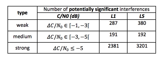
As might be expected, the most interference was detected in busy port areas. Less interference was experienced while transiting along coasts. While it was the least frequent, interference was still detected during open ocean transits.
Table: Emilio Pérez Marcos and co-authors
Of the 39,045 snapshots recorded, 6,632 contained radio frequency interference at 1dB or higher. Separate tests have shown that many single antenna GNSS receivers begin to perform poorly with interference signals greater than 1dB. The other 32,413 snapshots could represent interference signals that may have come from weaker transmitters, sources more distant from the ship, been the result of adjacent band transmissions, or other phenomena.
Three particularly strong and persistent interference incidents were noted in the paper.
The first was detected when the vessel was transiting the Suez Canal northbound. The interference lasted around five hours and 60km. At several points the interference prevented the DLR semi-resilient GNSS receiver from working properly, which would mean that any single antenna GNSS receiver would cease to function completely.
Vessel going north in Suez Canal. RFI detectable during approx. 60 km. Inset: Eigenvalues during the 5 hours that the RFI was detectable. (Graphic: Emilio Pérez Marcos)
The second caused the DLR receiver to fail when the vessel was entering Jebel Ali, the port of Dubai in the United Arab Emirates. The DLR receiver provided some resilience thanks to its beamforming capabilities; again any other receiver would have suffered the interference effects earlier being unable to provide any PVT. The receiver did not return to proper operation for 11 days and 5,000km. The reason for this is uncertain and under investigation.
Particularly strong interference (45dB) caused the third incident and resulted in the DLR receiver failing for three days. It began when the ship was entered the highly trafficked Malacca Straits.
The equipment used also allowed researchers to determine direction of arrival for the interfering signals and to evaluate whether the interference was a spoofing signal.
For the reported strong interference events, DLR consulted the captain of the ship, who attested and confirmed the loss of PVT in the ship’s own GNSS receiver, with all the consequences that this implies for the systems that rely on it.
The paper, “Interference and Spoofing Detection for GNSS Maritime Applications,” was presented at the ION GNSS+ conference in Miami in September of 2018. It described the last phase of a yearlong measurement effort aboard the ship by DLR. An earlier phase of the campaign has also been published in E. P. Marcos et al., “Interference awareness and characterization for GNSS maritime applications,” 2018 IEEE/ION Position, Location and Navigation Symposium (PLANS), Monterey, CA, 2018.
The authors are preparing additional papers to describe more of the results from the larger project.
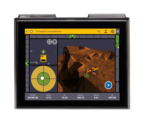
Trimble has introduced its Groundworks Machine Control System, a solution for drilling and piling operations. The next generation system that enables contractors to perform drilling and piling operations quickly, safely and accurately: with centimeter-level accuracy.
Using the large touch-screen display, operators can personalize the interface to match their workflow. In addition, a variety of configurable views make it easier for users to achieve maximum productivity. The software aligns with other solutions in the Trimble Civil Engineering and Construction portfolio to make company-wide training faster and easier.
“Engineered for ease of use, Trimble Groundworks features an updated, intuitive user interface designed for construction environments,” said Scott Crozier, general manager for Trimble’s Civil Engineering and Construction Division. “Contractors can achieve centimeter-level accuracy with stakeless navigation, which reduces rework and decreases the need for personnel working near the machine during operation.”
Drilling. Trimble Groundworks Machine Control System for Drilling gives contractors the ability to drill to the specified location, depth, orientation and inclination angle. Better rock fragmentation and lower hauling costs can be achieved by optimizing drill hole spacing, angles, and the location of the machine for a more even blasting pattern, according to the company. The auto stop feature automatically stops drilling at target elevation to reduce overdrilling, leading to flatter benches and reduced wear and tear on machines, which can result in significant cost savings.
Minimizing the need for stakes and construction surveying, Trimble Groundworks can help promote jobsite safety by reducing the number of people working near the machine while drilling. Also, avoidance zones can be set to keep operators from entering hazardous areas. With Trimble Groundworks, machines can operate 24 hours a day, 7 days a week in almost any conditions, decreasing the chance of delays due to darkness or inclement weather.
Piling. The system enables contractors to increase operational efficiency and reduce surveying costs associated with staking and as-built checks. Navigation time between piles is reduced. Less time moving the machine and more time piling maximizes daily production, which can increase revenue.
Built-in, automated quality assurance and quality control reporting includes the capture of start and end positions, time and elevation as well as actual embedment depth, blow count reporting, and inclination and orientation control. In addition, unique system logins allow managers to filter reports by operator for better accountability, production optimization and forecasting.