A leap-year bug caused some TomTom satellite navigation devices to malfunction, reports BBC News.
TomTom posted an information page on its website, offering a software update. “Some customers have been experiencing GPS positioning issues since 31st March,” TomTom said. “The issue is caused by a ‘leap year’ bug in the software of the GPS receiver provided by a third party.”
TomTom said that a problem with its global positioning system firmware had caused models worldwide to fail to identify their location, BBC News said.
The TomTom devices affected are:
Start 20/25
Via 110/120/125
Via LIVE 120/125
GO LIVE 820/825
GO LIVE 1000/1005/1005 World
Blue & Me TomTom 2
TomTom Connect
To download the firmware to their device, users will need to set up an account at the TomTom site if they don’t already have one.
The DNRGarmin application has been a popular tool for GPS users worldwide since 1999. Developed at the Minnesota Department of Natural Resources (MNDNR) to facilitate field data collection by staff, DNRGarmin use grew quickly soon after being released as freeware to the public. In addition to thousands of Minnesota users, DNRGarmin has been used worldwide by fishermen in Japan, search and rescue teams in New York, wildland firefighters across North America, professional adventurers in Brazil, and miners in Africa.
MNDNR has released numerous updates of DNRGarmin over time to add functionality and maintain compatibility with software and handheld GPS receivers. Escalating changes in technology, an expanding user base, and requests for additional functionality prompted DNR staff to examine new ways of maintaining the application.
DNRGPS is a new iteration of DNRGarmin created by MNDNR and the National Park Service. The new name reflects a focus to expand the compatibility of the application to more brands and models of GPS receivers. DNRGPS is also able to consume more geospatial data formats, has more data projections, and is compatible with the latest versions of ArcMap and Google Earth.
DNRGPS is being released as Open Source software so that any programmer can download and alter the code. It is hoped the Geospatial Community will “adopt” DNRGPS as its own, testing and checking-in enhancements to the code, thereby contributing to the timely maintenance and expanded functionality of the program for all users.
A public DNRGPS webpage has been created for the distribution of DNRGPS and accompanying documentation. The site highlights functionality, lists prerequisites, and includes links to DNRGPS mailing lists.
Nexteq, based in Calgary, Alberta, Canada, announces the release of its new RTK-F (Real Time Kinematic Float) positioning augmentation system for its T6 GNSS handheld (at right). RTK-F is well suited for demanding applications by providing the highest accuracy available for the T6, Nexteq Navigation said. With RTK-F, the T6 reaches a consistent 20-centimeter accuracy level, further improving upon the unit’s sub-meter level accuracy currently available with Nexteq’s Freedom or i-PPP point positioning technologies. The addition of RTK-F further enhances the flexibility of the T6 platform.
The T6 RTK-F augmentation system utilizes RTCM messages with code and phase corrections from reference networks or stand-alone base stations. These corrections can then be transmitted over the Internet with non-proprietary hardware, drastically improving efficiency and giving freedom of movement to the user with minimal latency, Nexteq said. Further, Nexteq Navigation’s upcoming T5A GNSS handheld can be used as a reference base station for RTK-F, eliminating the need for costly subscriptions to corrections from commercial sources.
Like all Nexteq Navigation handhelds, the T6 is a ruggedized and tough unit. The T6 has an IP66 rating with excellent dust and water resistance, Nexteq said.
The National Academies Press has released Global Navigation Satellite Systems, the report of a joint workshop of the National Academy of Engineering and the Chinese Academy of Engineering held in Shanghai, China, on May 24 and 25, 2011.
According to the NAP, “The workshop featured presentations chosen based on the following criteria: they must have relevant engineering/technical content or usefulness; be of mutual interest; offer the opportunity for enhancing GNSS availability, accuracy, integrity, and/or continuity; and offer the possibility of recommendations for further actions and discussions. Global Navigation Satellite Systems is an essential report for engineers, workshop attendees, policy makers, educators, and relevant government agencies.”
The 268-page report is available in both printed and electronic form. One may download either individual chapters or the complete report for personal use free of charge.
DMTI Spatial (DMTI) is sponsoring Expedition ’12: The Value of Location, its fourth annual user conference.
As Location Intelligence continues to become one of the biggest waves in technology, it’s never been more critical to understand the impact it will have on your business, organizers said. This conference will be held at The Fairmont Royal York Hotel in Toronto, Canada.
Register before April 23 to receive a 10 percent discount off the delegate fee of $99.
u-blox, the Swiss positioning and wireless module and chip company, announces an all-in-one satellite positioning receiver module, the LEA-6N. The low-power, cost-effective module delivers fast, high-accuracy positioning, u-blox said. It is targeted at industrial telematics applications in Russia such as vehicle tracking, mobile resource management and the ERA-GLONASS emergency call system.
The module works with GPS, Russian GLONASS, and Japanese QZSS satellite positioning systems. It also supports all civilian Satellite-Based Augmentation Systems (SBAS).
“The LEA-6N module delivers clear new benefits for our industrial customers in terms of global support of all available satellite positioning systems, easy to mount LCC form factor, low power consumption and cost effectiveness” said Thomas Nigg, VP Product Marketing at u-blox, “LEA-6N will also support our CellLocateTM hybrid indoor positioning system; when used together with our wireless modules, the location of valuable assets or people can be determined anywhere, indoors and outside.”
Samples of LEA-6N are available mid-April 2012, with evaluation kit EVK-6N and mass production in June 2012. For more information, contact the u-blox office nearest you, or visit with company representatives at Machine to Machine 2012 stand E21 April 3-5 in Paris.
Spectra Precision introduced today the new ProFlex 800, a GNSS solution with Z-Blade GNSS-centric technology. The ProFlex 800 delivers fast and reliable RTK positioning, even in environments where GNSS signals may be difficult to acquire, Spectra Precision said. Rugged and IP67 rated, the ProFlex 800 is built to withstand harsh operating conditions for a variety of positioning applications.
“The ProFlex 800 is an ideal solution for customers wanting a single GNSS receiver for multiple applications,” said François Erceau, general manager of Trimble’s Spectra Precision, Nikon and Ashtech Business Area. “It offers a unique design with a range of mounting and communications options.”
Used as a backpack rover or reference station, the ProFlex 800 with Z-Blade technology is a flexible GNSS solution for land surveying. Its innovative design also makes it ideal for hard-mounted survey applications such as coastal work, dredging, bathymetry or offshore vessel operations.
The weatherproof, high-impact-resistant molded aluminum housing allows the ProxFlex 800 to operate in harsh conditions.
In addition to a 3.5G internal cellular modem, the ProFlex 800 can use a variety of internal or external UHF modules, providing stable and reliable wireless communications. It can be used as a rover or a base without additional accessories in the field. Its Z-Blade long-range RTK capability combined with industry-leading UHF options help to ensure maximum productivity while in the field.
With its built-in Ethernet capability and embedded web server, users can access the ProFlex 800 from any computer connected to the Internet. This capability allows instant real-time multi-data streaming over an Ethernet connection to build an RTK corrections server without any additional software or equipment, the company said.
Spectra Precision ProFlex 800 CORS Receiver. The Spectra Precision ProFlex 800 is also available as a Continuously Operating Reference Station (CORS). This configuration is an optimal solution when collecting, storing and transferring high-quality GNSS raw data for post processing surveys, geodetic and other applications. Automatic sessions programming, a user-friendly Web-interface, an embedded RINEX converter, FTP push functionality and many other advanced CORS features make the ProFlex 800 CORS a powerful, robust and easy-to-use GNSS solution.
Advanced Ashtech Z-Blade Technology. Z-Blade is a new GNSS centric signal processing technology. Z-Blade uses all of the available satellite signals equally, without preference to any particular satellite constellation, maximizing the user’s ability to obtain reliable GNSS positions in tough conditions. Z-Blade allows users to receive and maintain RTK positioning even if GPS coverage is insufficient. In many work locations, just a few GPS and GLONASS satellites may be visible due to obstacles such as trees or buildings.
The ProFlex 800 is now available through the Spectra Precision global dealer network. For more information visit: www.spectraprecision.com and www.ashtech.com or email: [email protected]
OriginGPS is making available the first samples of its OriginGPS 1410 GPS receiver. The OriginGPS 1410 is 10 x 10 millimeters in size and has an active integrated antenna. The ORG1410 is a complete GPS System–in–Package (SiP), which allows high-volume, cost-sensitive applications to achieve high levels of integration and sensitivity, combined with low power consumption and an ultra-compact footprint, OriginGPS said.
OriginGPS is able to offer the first samples and development kits for this benchmark product through its representatives across the world. These representatives support customers with design support and manufacturing services that will allow customers to push their products’ GPS capabilities to new levels of performance and functionality, OriginGPS said.
The integration of a SiRFstarIV GPS processor enables the ORG1410 to operate in challenging GPS environments, such as tracking indoors or when the end-user is on the move. This high level of GPS performance is achieved by using GPS firmware that can detect changes in context, temperature, and satellite signals, and opportunistically update its internal parameters that enable the ORG1410 to deliver near-continuous navigation, the company said.
Within its 10 x 10 millimeter package, the ORG1410 integrates an active antenna; RF shield; TCXO and RTC crystal; LNA and SAW filters; and UART, SPI or I2C host interfaces, while achieving ultra-low power consumption of less than 15mW and a fast position fix of under 1 second and sensitivity of –163dBm.
A limited number of ORG1410 samples, in addition to development kits for leadcustomers, are available immediately.
Polaris Wireless, a provider of software-based wireless location solutions, announced that Per K. Enge of Stanford University has joined its executive team as the chief technical advisor. In an interview with GPS World, Enge describes how combined wireless location signatures and GPS show an exciting way forward for location in dense urban environments, where the wireless solution actually improves as GPS degrades.
Polaris Wireless, a provider of software-based wireless location solutions, based in Mountain View, California, announced that Per K. Enge has joined its executive team as the chief technical advisor to the company’s CEO, Manlio Allegra.
Enge is a professor of aeronautics and astronautics at Stanford University, where he directs the GPS Research Laboratory. He is also is co-author of the textbook Global Positioning System: Signals, Measurements, and Performance and has received the Kepler, Thurlow, and Burka Awards from the Institute of Navigation (ION) for his work. He received his Ph.D. from the University of Illinois in 1983, where he designed a direct-sequence multiple-access communication system that provided an orthogonal signal set to each user.
Polaris Wireless’s core product is a Wireless Location Signature (WLS) for wireless network operators to identify the location of a wireless device to within 50 meters, at low cost, even in urban and indoor environments. Polaris WLS is designed to scale as an operator’s network grows, providing location capabilities in 2G (GSM/CDMA), 3G (UMTS/CDMA 2000), and emerging 4G (LTE) air interfaces, as well as indoor technologies such as W-iFi, DAS, and Femtocells. Founded in 2003, Polaris also counts among its customers law enforcement/government agencies and location-based application companies.
In an interview with GPS World, Enge described how the Polaris location solution is actually enhanced by buildings, in direct opposition to the way GPS operates, and how he sees integration of the two technologies as leading the way forward for location-based services.
“A cell phone general receives signals from 3 to 10 base stations, and is required to report the signal to noise ratio of those, even beyond base station used. We backhaul that information into the Polaris server, where we do multilateration based on signal strength measurements. Imagery shows how RF signal stregnth varies in the city. Polaris uses the base station signals (similar to how Skyhook using Wifi access points), but the cell infrastructure use is better because it is always there and used by every phone, while Wifi receiver is not on all phones yet, just smartphones.
“Marriage to GPS is very cool, because the Polaris technology loves buildings, they introduce the variation, the grain in the signal-strength map. It’s jagged, it’s got nooks and crannies, which are well-predicted by our propagation models. So those buildings enhance our technology.
“We’ve got it pretty widely deployed, on 24 E911 networks, 24 wireless carriers that we have commercial relationships with in the United States, from quite big to more boutique providers. Some are smaller, regional, other larger, like Verizon though not the total network.
Michael Doherty, Polaris Wireless product marketing and communications director, added that “We also work outside the United States for location surveillance for governments who are also looking to deploy for commercial services. The solution is software-based, in the control plane of the handset, it is already within the handset, using network measurement reports (NMRs). Emergency caller location for cell phones, E911, is just the first of applications to come, it’s where we cut our teeth.”
Polaris Wireless has been a research partner and sponsor at the Stanford GPS Research Laboratory that Enge directs. “Now I’ve stepped up my relationship with them, to start talking about getting the next level of accuracy. They joined about 4 or 5 years ago, and funded the work of David De Lorenzo , a Ph.D. student who did first big set of measurements that we did on indoor navigation, on GPS penetration into buildings. On campus. We’re aviation people, so this was a new area, good for us, we expanded into that area and got a lot smarter about how to navigate indoors.”
De Lorenzo’s 2009 Institute of Navigation International Technical Meeting paper, “Design and Performance of a Minimum-Variance Hybrid Location Algorithm Utilizing GPS and Cellular Received Signal Strength for Positioning in Dense Urban Environments,” can be accessed here.
“In New York, three-quarters of cell calls get 50-meter accuracy,” stated Doherty. “99 percent get 150-meter. Polaris solutions will improve that by a factor of 2. That’s a forward-looking statement.”
“We are entering a significant growth period for the company. From 2007–08 we saw our business start to take off, from core E911, take off in demand from overseas governments, for anti-crime, anti-terrorism. From 2007 to 2010, Polaris Wireless had an average 66 per increase per year in bookings, in contracts signed. That’s a healthy indicator of future revenues
“Year over year 2010 to 2011, we saw a quadrupling of bookings, and a revenue increase of 30 percent, as we started to see those deployments taking place, and revenues coming in as a result. we expect that trajectory to continue through 2012 and 2013. Again, forward-looking statements.”
“During the deep recession, when U.S. governments were cutting back, we went overseas and were able to ride that wave.”
As to particulars on directions that Polaris research and development might take under his advisement, Enge volunteered “One of the really big initiatives is the inclusion of map-matching, knowing that we’re probably on a street, especially if our velocity is appreciable, going beyond a snapshot solution fix, taking advantage of knowing where streets our. We have cached that as a particle-filter problem, a Kalman filter associated with a set of hypotheses. When you have a sequence of snapshots, the particle filter is a very powerful way of putting that together.
“How do we know if we’re in a building? By looking at the NMRs. Now, how high are we in that builidng, so that’s aided by the database.
“The big core enterprise of Polaris, stripping away PNT, the strength is the underlying [cellular network] database. Polaris is where the database meets navigation. To make E911, law enformcement, navigation, all better.
“One application I’m particularly keen on is for campuses.The risk for muggings is greatest when walking to a car in a distant parking lot. We’re thinking about how we can help that student when assaulted. You can’t pull out your phone and call E911 nor run to a blue tower [emergency phone]. But you might have your keys in your hand, so if we make it so you can just push a button on it, the NMR goes to an emergency center on campus, then we can be more helpful in helping that student.”
Doherty inserted, “The beauty of our technology is that no one has to do anything. Our technology is capable of locating any device connected to the cellular network, as long as the device is powered on. It’s a software deployment, nothing to go out and deploy equipment cell tower by cell tower. Nor can bad guys disable anything in the phone to void this service. Polaris’s solution resides in the network, not in the handset. The confluence of signals in the network drives the solution. There is no chip in the handset that can be disabled or turned off. Whether GPS is enabled or not.”
In a final comment on concerns for the future, Enge said, “Personal privacy devices, PPDs, the GPS jammers. I’m pretty worried about that. Unlike the Polaris technology, GPS technology can be slapped on someone’s car without an organization making sure the rule of law is preserved. We’re hoping to make the PW technology complementary to GPS, so that when GPS is jammed, the PW solution will still provide a location.
Doherty added, “It is complementary today. Cellular networks covers a large area. Take for example, downtown San Francisco: The wireless signature solution is absolutely the best to locate there. In wide-open country, GPS has an advantage. That complementarity is happening today.
“Having Per onboard, we’re going to make that complementarity work better and better.”
As result of a Cooperative Research and Development Agreement (CRADA) between the U.S. Coast Guard and UrsaNav, Inc., on-air tests are being conducted from the former Loran Support Unit site in New Jersey.
One of the CRADA’s goals is to research, evaluate, and document a wireless technical approach as an alternative to GPS for providing precise time. The ability to obtain precise time to at least one microsecond is necessary for the proper operation and functioning of many critical industries and systems. Examples include telecommunications networks, banking and finance, energy and power delivery, emergency services, transportation systems, and military and homeland security systems.
Additional on-air tests are planned at various sites throughout the United States. Broadcasts will test several different frequencies, waveforms, and modulation techniques using evolutionary, state-of-the-art technology. Reception of these broadcasts are planned at both on-shore and off-shore locations, and will include advanced LF data delivery techniques. The results of these trials will be presented at national and international conferences. Parties interested in any part of the trial, or interested in doing their own measurements, are invited to contact UrsaNav.
The company has partnered with precise-time synchronization company Symmetricom and Nautel, supplier of high-power RF transmitters. According to UrsaNav, this “alliance of expertise” provides the foundation technology for a wide-area, terrestrial-based alternative to satellite systems such as GPS, GLONASS, and Galileo.
“Global government, industry, and academic experts recognize that advanced LF signals, of which eLoran is just one example, can provide alternative timing — either as a stand-alone service, or as a component of an existing positioning, navigation, and timing (PNT) service. The high-power, virtually jam-proof and spoof-proof LF signals operate independently of GPS and GNSS, and provide a Universal Coordinated Time (UTC) time reference in the order of tens of nanoseconds. The recognition of the criticality of time to many aspects of our national critical infrastructure has led to establishment of the CRADA to evaluate the benefits of an LF wide-area timing system.”
The LF signals can also be used as pseudoranges mixed in with GPS, or if enough transmitters are available, as a fully independent PNT network. In other words, a true backup PNT capability for safety-of-life navigation, for dispatching first responders, and for supporting critical national infrastructures.
First Galileo PRS Signal Received
Septentrio and QinetiQ, in close partnership with the European Space Agency (ESA) and their industrial partners, achieved the first successful reception of the encrypted Galileo Public Regulated Service (PRS) signal from the first Galileo satellites, launched in November 2011.
The signal was received on the Galileo PRS Test User Receiver (PRS-TUR) jointly developed by Septentrio (Leuven, Belgium) and QinetiQ (Malvern, United Kingdom) under an ESA contract. For the reception test, the receiver was installed in the Galileo Control Centre in Fucino, Italy, and operated by technical experts from ESA.
Septentrio and QinetiQ are long-term contributors to the Galileo Programme, working closely with ESA, the European GNSS Agency (GSA), and European industrial partners since 2003.
Count Five Compass IGSOs
The BeiDou-2/Compass G5 satellite launched on February 24 has achieved an initial approximately geostationary orbit.
The current sub-satellite east longitude is 57.23 degrees. The intended final orbital slot may be 58.75 degrees, one of the previously announced orbital locations and one used by the BeiDou-1 demonstration system.
The 2012 NextGen Plan specifically mentions GPS/GNSS as follows:
Performance Based Navigation (PBN). The current aircraft fleet is well equipped with PBN capability. In the air carrier community, the heart of the PBN capability is the Flight Management System, which uses input from multiple distance measuring equipment (DME), or from the GNSS using a GPS sensor or a GPS with Wide Area Augmentation System (WAAS) sensor.
Ground Based Augmentation System Landing System (GLS) Enabler. This program researches use of differential GPS corrections to support Category III (Cat III) approaches. This capability will be the same as Cat III instrument landing system (ILS), without the need to restrict taxiing aircraft near antennas and at reduced cost to the FAA.
Automatic Dependent Surveillance–Broadcast (ADS-B). Aircraft position (long-lat, altitude, and time) is determined using GPS, an internal inertial navigational reference system or other navigation aids. ADS-B Out involves transmission of a GPS position (or of comparably performing navigation equipment meeting integrity and accuracy requirements) from an aircraft to display its location to controllers on the ground or to pilots in other aircraft equipped with ADS-B In.
Low-Visibility/Ceiling Approach.Localizer Performance (LP) with Vertical Guidance (LPV) Approaches. These are more cost-effective to implement compared to additional ground-based navigation aids (NAVAIDs) and their approach procedures. Increasing the number of LPV/LP approaches will provide further incentives for users to equip with GPS/WAAS. This will provide increased utility to the more than 40,000 general aviation aircraft that are already WAAS-capable. The FAA will also deliver LP approaches to runways that do not qualify for LPVs due to obstacles.
Ground Based Augmentation System (GBAS) Precision Approaches. GPS/GBAS support precision approaches to Cat I and eventually Cat II/III minima for properly equipped runways and aircraft. GBAS can support approach minima at airports with fewer restrictions to surface movement and offers potential for curved precision approaches. GBAS may also support high-integrity surface movement requirements.
— Bill Thompson, GPS World aviation editor
LightSquared-Sprint Contract Terminated
Business Case for GPS Threat Gone Away
The principal business prop under the LightSquared plan for ancillary terrestrial component (ATC) broadcast of a powerful signal that would have disrupted GPS operations dropped out from under the company on March 16, as wireless carrier Sprint terminated its $9 billion agreement with LightSquared. LightSquared had several such partnership agreements, but the Sprint deal was the largest, and in many eyes the driver of the aggressive plan. With it gone, LightSquared’s other deals will likely dissipate — and the current threat, at least, to GPS industry and users should effectively go away.
Sprint has apparently concluded that LightSquared has no prospect of reversing the revocation of its conditional waiver last month by the Federal Communications Commission, as a result of extensive testing conducted by the company, various government agencies, and the GPS industry. Earlier, Sprint had twice extended its tentative agreement with LightSquared as the tests took place over the last year, but reached the end of its road March 16 — which is also the last day the FCC is accepting public comments on its decision to revoke the waiver.
An official LightSquared statement said termination of the Sprint agreement was “in the best business interests of both companies, and was not unexpected given the regulatory delays.” Sprint will return $65 million in prepayments that LightSquared made to Sprint.
Some analysts have predicted that LightSquared may be forced to sell off its assets by the end of the year. Among these assets are the spectrum licenses for the lower LightSquared band (1526–1536 MHz), the so-called Low 10, and the higher band (1545-1555 MHz), known as the Upper 10, adjacent to GPS L1. These bands have a history of trading hands as their owners go into bankruptcy or otherwise out of business.
The next touchpoint of concern for the GPS community is the outcome or perhaps various outcomes of the FCC workshop on spectrum efficiency and receivers that took place March 12–13. The workshop was convened to discuss the characteristics of receivers and how their performance can affect the efficient use of spectrum and opportunities for the creation of new services, according to the FCC.
By Holly Borowski, Oscar Isoz, Fredrik Marsten Eklöf, Sherman Lo, and Dennis Akos
A component of most GPS receiver front-ends, the automatic gain control (AGC) can flag potential jamming and spoofing attacks. The detection method is simple to implement and accessible to most GPS receivers. It may be used alone or as a complement other anti-spoofing architectures. This article presents results from a baseline AGC characterization, develos a simple spoofing detection method, and demonstrate the results of that method on receiver data gathered in the presence of a live spoofing attack.
Growing reliance on GNSS also creates the need to defend against those with the ability to exploit its weaknesses. Specifically, GNSS signal spoofing is recently a growing concern, as an effective spoofing attack can fool a GNSS receiver into producing erroneous navigation and timing information. Although applicable to many GNSS, GPS will be used as the example.
One example of spoofing seen recently in the popular press was the Iranian claims of bringing down a U.S. unmanned aircraft via a GPS spoofing attack. Although this may be unfounded given the complexity required, spoofing attacks to autonomous vehicles are emerging threats. A second hypothetical example is a fisherman whose location is monitored using GNSS may be motivated to use spoofing, such that illegally fishing in protected waters is not detetcted, increasing profits.
GPS signals received by a traditional hemispherical antenna are below the thermal noise floor, a physical constant dependent only on temperature. Although multiple signals are transmitted at low power in the same frequency band, they can be acquired and tracked using code-division multiple-access (CDMA). However, low signal power also makes GPS systems vulnerable to intentional radio-frequency interference (RFI) and the more sophisticated spoofing.
Spoofers range from simple to sophisticated. For example, a simple spoofer may be built from a GPS repeater (known as meaconing) by simply using it to rebroadcast signals at a higher power than the authentic GNSS signals. Receivers close enough to these spoofers then acquire and track the stronger spoofed signal, producing an erroneous position/timing solution. In this case, a position jump is likely to occur in the victim receiver’s reported solution as it transitions from the true signals to the spoofed signal, alerting the user of a potential spoofing attack. Somewhat more complex than a simple repeater would be to broadcast signals from a GPS simulator, which would enable a threat with more control over the signal-to-noise ratios as well as the resulting position. Finally, a very sophisticated spoofing attack first introduced by Humphreys , et al. in 2008 may be implemented by placing a spoofer near the receiver, so that it can correctly align its transmitted false signals to the authentic ones seen by the victim receiver. The spoofer then gradually increases the power of its transmitted signals, eventually capturing the receiver. After the receiver begins tracking the false signals, the spoofer can gradually deviate its transmitted signals from the authentic ones, causing the victim receiver to produce false navigation and timing information.
Effective methods have been developed for distinguishing spoofed from authentic GPS signals with a summary most recently presented in a January 2012 GPS World article by Wesson, Shepard, and Humphreys. In short, these methods can be divided into cryptographic and non-cryptographic spoofing detection schemes.Unfortunately the presented methods are not readily available to the majority of current standalone GPS receivers and can be quite computationally expensive.
We suggest a method using the Automatic Gain Control (AGC), a component of most GPS receiver front ends, to flag potential jamming and spoofing attacks. The proposed spoofing detection method is simple to implement and accessible to most GPS receivers as a measure of confidence in the authenticity of received and tracked signals. It may be used by itself on receivers without other spoofing detection capabilities or to complement other anti-spoofing architectures.
AGC Background
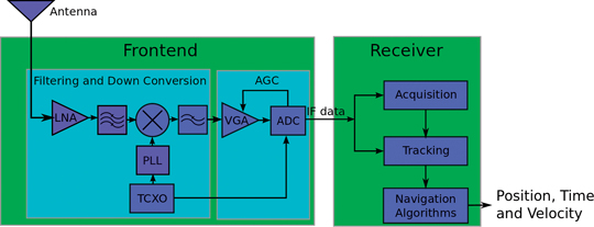
GPS receivers consist of an analog portion and a digital portion: the analog signal, comprised nominally of GNSS signals and white Gaussian thermal noise, is received, amplified, down-converted, and filtered, then converted to a digital signal for processing within receiver acquisition and tracking loops. During signal sampling and quantization by the Analog to Digital Converter (ADC), some quantization losses will occur. These losses depend on the ratio between the ADC’s maximum quantization threshold, L, the number of bits utilized, and the incoming signal standard deviation, σ.
This is where the AGC comes in. In a typical GPS receiver, it sits between the analog portion of the front end and the ADC, as shown in Figure 1. The AGC acts as a variable gain amplifier, adjusting the power of the incoming signal to optimize the L/σ ratio, minimizing quantization losses. This assumes the receiver is a multibit design which is the norm for GPS receivers today.
FIGURE 1. Typical GPS receiver architecture.
When the GPS band is interference free, which should be the norm due to restrictions on emissions in and near the band, the AGC gain depends almost exclusively on thermal noise, since the received GPS signal power level is below that of the thermal noise floor. Since this thermal noise is a physical constant with minimal fluctuation resulting from the span of temperature variations on earth, the primary role of the AGC is to adjust to different active antenna gain values. However, in the unlikely presence of interference the AGC gain drops in response to increased power in the GPS band. Thus, AGC levels may be used to indicate potential interference. Moreover, AGC levels are expected to respond to the interference before receiver performance is compromised, so useful flags may be established, which could provide a warning before a problem exists.
Baseline AGC Data Gathering
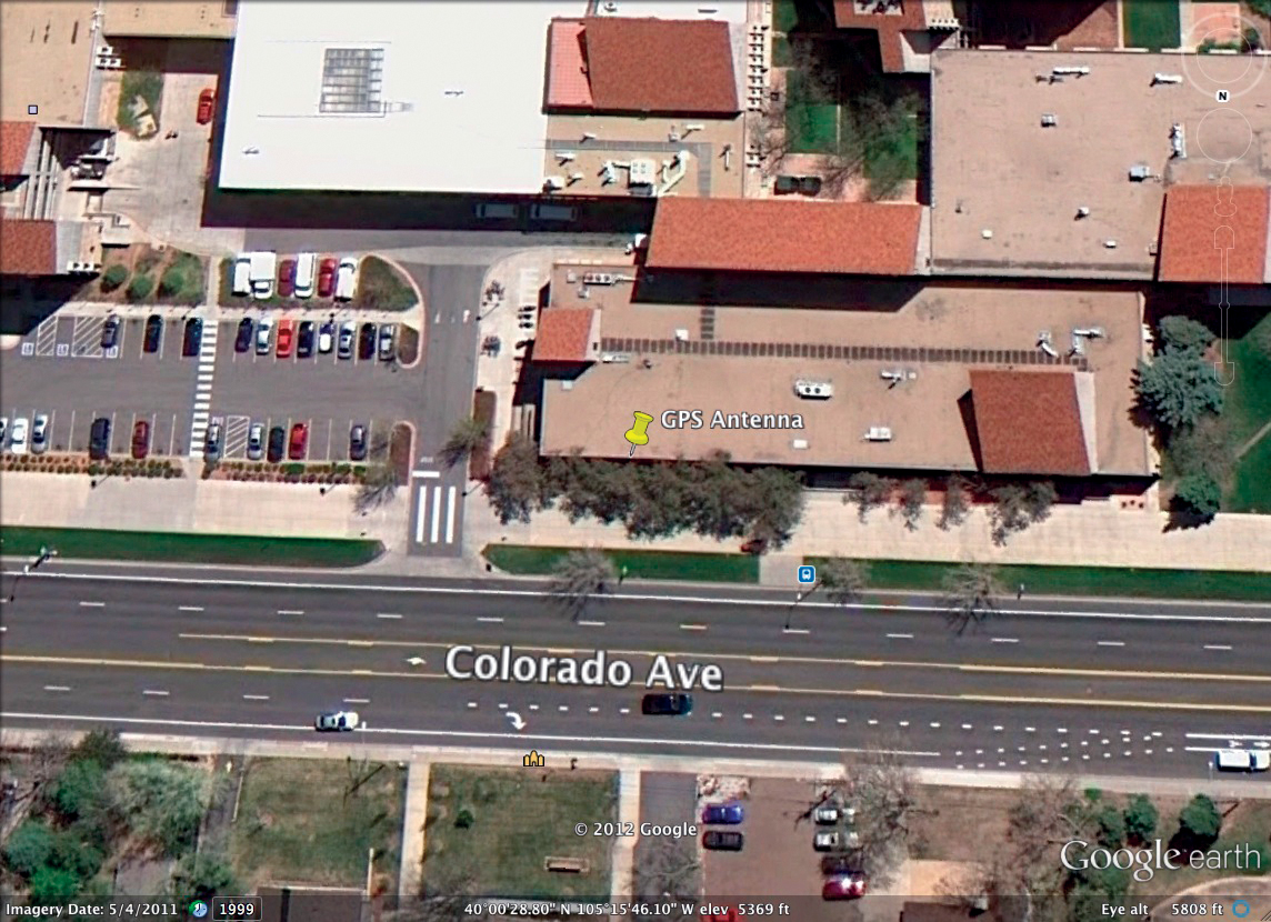
Prior to the spoofer experiment, baseline AGC data were collected for 72 hours using both a survey grade and a mass market receiver. The GPS antenna was located on the roof of the Engineering Center at Colorado University (CU) in Boulder (Figure 2).
FIGURE 2. Antenna location for baseline AGC data collection.
Currently there is no standardization among GPS receivers for AGC reporting units or the measurement itself. Most receivers offer such a metric but it is likely that each needs to be interpreted individually. However, in general this metric provides an indication of the relative gain of the amplifier within the receiver. Should the active antenna be disconnected (loss of gain), the AGC metric will increase showing the increase in internal gain needed to compensate for the loss of the active antenna amplification of the thermal noise floor. Should additional energy be detected in band, the internal gain will decrease accordingly.
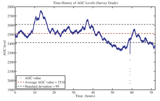
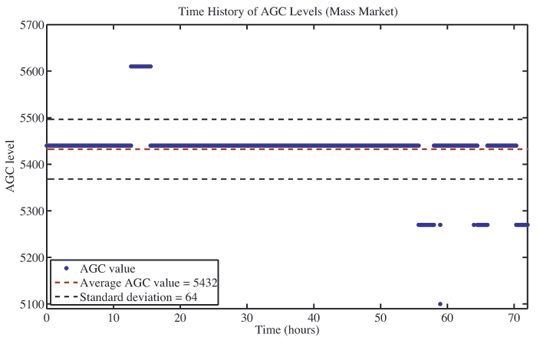
Baseline AGC levels from the survey grade and mass market receiver are shown in Figures 3a and 3b, respectively. The survey grade receiver AGC measurement was more sensitive to changes in the nominal environment; these results will be discussed later in more detail. The mass market receiver provided a much more consistent measure for the entire test period. Interestingly, there was one brief yet noticeable drop in AGC metric from the survey grade and mass market receivers at approximately hour 59 into the collection. Its magnitude was not overly significant, as it did not have an impact on the availability or accuracy of the position solution measurements from either receiver. It is assumed that this is a brief RFI event that occurred during the collection, perhaps from an illegal personal privacy device (PPD) in a vehicle on the nearby road.
FIGURE 3A. Nominal AGC values for survey-grade receiverFIGURE 3B. Nominal AGC values for mass-market receiver.
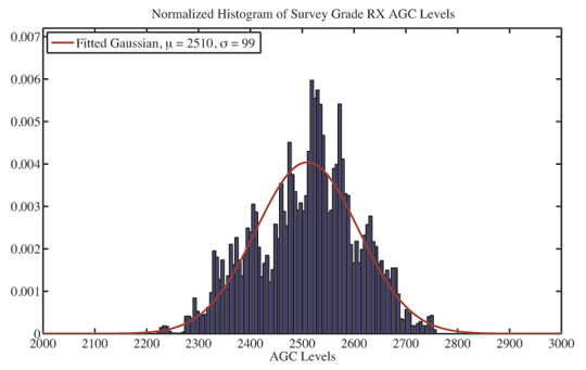
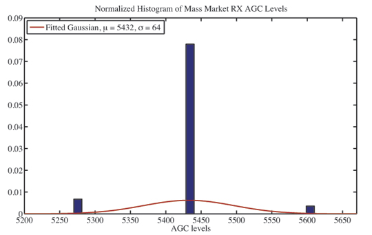
This RFI event outlier was excluded from the computed mean and standard deviation from the receivers’ AGC data. As shown in Figure 4a, the mean reported AGC gain was approximately 2510, and its standard deviation was approximately 99. For the mass market receiver, the data shows clear evidence of quantiztion in Figure 4b. Here the mean AGC level in this test was approximately 5432, standard deviation was approximately 64. Again, the absolute measures mean little and cannot be compared from various vendors of receivers. It is, of course, possible to calibrate individual receivers and obtain an absolute measure should this be required for a specific application. During the baseline data collection receiver reported position solutions were nominal, with deviations on the order of 2-3 meters in east and north directions, and 5-6 meters in the vertical direction for both receivers. A Gaussian curve was fit to the AGC data and although the data may not be well modeled by a Gaussian, a 2x standard deviation will be used to establish a quick initial flag to indicate potential spoofing/interference.
FIGURE 4A. Histogram of survey-grade AGC data.FIGURE 4B. Histogram of mass-market AGC data.
AGC Reactions to Live Spoofing
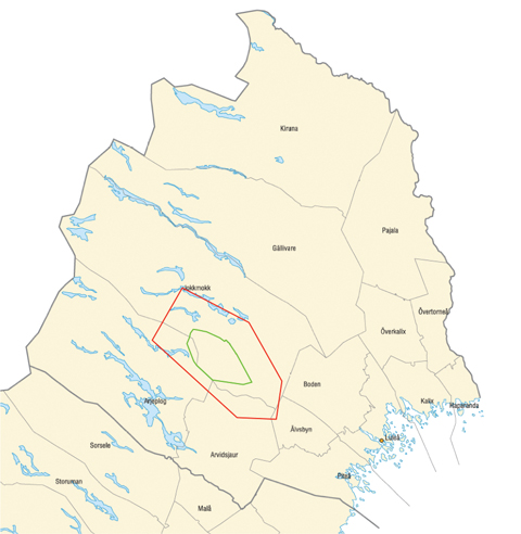
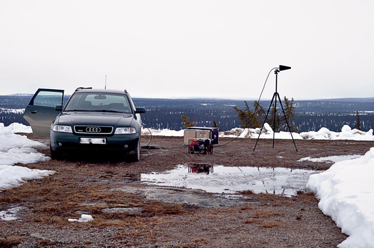
Live RFI or spoofing experiments are quite difficult to conduct due to the global and national legislation protecting the GPS frequency band. Any such experiments tend to be conducted with significant advanced planning and in locations where the testing will have no impact on any system or application which uses GPS outside the test range. Thus, we are grateful to have been able to test the AGC detection of live transmissions in the GPS band. This was done at the Robotförsökplats Norrland test range in Northern Sweden (Figures 5A, 5B, 5C) with the support of the Swedish Defense Research Agency.
FIGURE 5A Robotförsökplats Norrland test range in Northern Sweden (green outline is the test range and red outline is the flight restriction area, approximate 130 x 70 kilometers).FIGURE 5B Repeater spoofer transmission antenna.FIGURE 5C. Test vehicle
Dynamic GPS receiver measurements (position and AGC) from both the survey grade and mass market receivers were logged in the presence of repeater spoofing. Tests performed involved installing GPS antennas on the rooftop of a vehicle and driving along a 4km stretch of road toward (and away) from a hill top repeater spoofer transmission antenna while logging AGC levels and receiver positions from various GPS receivers. The data from both the survey grade and mass market receivers, used in the baseline collections, will be used here. The repeater spoofer source and transmissions antennas and the road (color shaded by elevation) used to go to/from the spoofer transmission antenna are shown in Figure 6.
FIGURE 6. Google Earth view of testing environment.
The baseline receiver data was used to establish the change in AGC levels necessary to flag potential jamming, spoofing, or unintentional RFI. In order to implement the AGC flag proposed in this paper, a known fixed RF chain (antenna, cable, and front end) would be calibrated in a known non RFI environment and the mean AGC would be established. Given the baseline data collection, a mean value has been established and a 2σ threshold is set as the RFI/Spoofing flag for each receiver. When the AGC drops below this flag, the resulting position/time solution should not be trusted.
In Figure 7 the measurements (AGC metric and survey receiver reported position) are shown as a function of time as the receiver is driven toward the spoofer transmission antenna. Under nominal conditions (no RFI or spoofing) one would expect a constant “safe” AGC value as well as a smooth gradual change in the reported XYZ coordinates (as the drive maintained a constant speed on the road for the duration of the test). However, as expected, due to the additional power in the GPS band, the AGC gain drops as the receiver gets closer to the repeater spoofer. At approximately 138 seconds the receiver fails to report a position and this continues for the next 30 seconds as the vehicle progresses toward the spoofer transmission antenna. At approximately 168 seconds, the survey receiver is captured and reports the fixed position of the spoofer source antenna despite continually moving toward the transmission source. Although the loss of lock and position jump could be utilized as a flag for spoofer detection, the AGC metric here clearly shows the additional power in the band prior to any corruption of the reported GPS receiver position. If the previously computed threshold is used here, the 2σ trigger occurs as the AGC level begins to drop, significantly before any loss of lock or any change in the position solution resulting from the repeater spoofer.
FIGURE 7. Survey-grade RX AGC/position during drive toward spoofer.
Figure 8 shows this same data for the mass market receiver with similar observations. First, and most importantly, the AGC metric can be used here as a flag well before any corruption of the resulting position solution. The resulting position solution as the receiver becomes “captured” by the spoofer is odd, not going directly to the repeater source antenna location but also not maintaining the true position either. Likely a result of the navigation filtering coupled with individual range measurements transitioning from the true satellite measurements to that from the repeater spoofer. Nevertheless, it is clear from the AGC metric that the receiver output should not be trusted , well before any misleading information is provided.
FIGURE 8. Mass-market RX AGC/position during drive to spoofer.
Figure 9 shows AGC levels and reported positions for the survey grade receiver as it is driven away from the repeater spoofer. At the beginning, the receiver is already captured by the spoofer and reports a false fixed position solution even while the vehicle is moving. While in close proximity to the spoofer, the AGC levels are low, attempting to compensate for the additional power in the GPS band. This would be an obvious flag that the resulting position cannot be trusted (all measurements to the left of the threshold are considered untrustworthy). As the receiver is driven away and exits the spoofer’s region of influence, power levels in the GPS band return to normal, the AGC reacts accordingly by increasing its gain, and the receiver begins to report accurate position solutions.
FIGURE 9. Survey-grade RX AGC/position during drive from spoofer.
Figure 10 shows this same data for the mass market receiver with similar observations. The AGC metric can be used as a flag indicating the position solution cannot be trusted until the receiver is well outside the range of the repeater spoofer. In this test, the AGC level does not return to a level within the established threshold, indicating that GPS solutions should not yet be trusted. This is likely a result of an overly conservative threshold (perhaps from the poor fit of data which is not well represented by a Gaussian) or perhaps hysteresis or smoothing in the AGC metric for this receiver.
FIGURE 10. Mass-market RX AGC/position during drive from spoofer.
These cases are representative of similar repeater spoofing tests we performed: in all cases this trigger identified potential interference well before the receiver reported false positions with the simple triggers established.
Improvements and Optimizations
These results do demonstrate the power of AGC to detect deception in GPS transmission, rendering these spoofers no more of a threat than the much less sophisticated jammers. However, the spoofer used in this testing was of a simple nature — a repeater spoofer.
The challenge would be to utilize such an approach to detect the most sophisticated spoofing attacks. This should be possible as the underlying thermal noise floor is a physical constant and in order for a receiver to be spoofed additional energy must enter the RF chain which, again, should be detectable. The optimization will come in via establishing thresholds – similar to GPS signal acquisition/detection. One will not want to set such a loose threshold such that frequent false alarms provide little confidence in the resulting position/time solution. Likewise one would not want to establish threshold so loose that the more sophisticated spoofing attacks would be successful. The key is the calibration and assessment of the underlying AGC measurement.
Recall the variation observed in the survey grade receiver data. Was this truly random noise that one must overbound as was done to establish the threshold for the experiments in this paper? And why were the noise levels so different for the baseline AGC collections in the survey grade and mass market receiver? We try to address both of these questions to provide a bit of insight into the advantages and shortcomings of the AGC metric.
First, the AGC measurement across receivers is not equal. In comparing these two receivers, the survey grade receiver has a much higher resolution measurement than that of the mass market receiver. This is obvious from the baseline data which showed little deviation from specific quantized levels in the mass market AGC metric. So although the great majority of GPS receiver already have/report their AGC measurement it may not be of sufficient fidelity for the most sophisticated spoofer detection.
Second, high resolution provides little benefit in a noisy measurement. So there is a pending question if there is a source for the variation in the AGC measurement for the survey grade receiver during the 72 hour baseline data collection – or was it simply a noisy measurement. Past work in this area led to the association of ambient temperature and the AGC measure, but perhaps not in the way one would initially think. Yes, the thermal noise level is dependent on temperature (from kTB), as well as bandwidth and Boltzmann’s constant, but this is really antenna temperature and in this case the correlation is with ambient temperature.
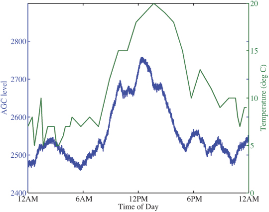
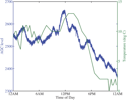
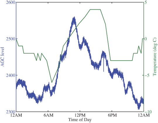
The baseline AGC levels were compared to changes in ambient temperatures in Boulder during testing to determine if observed fluctuations were related to temperature. The weather data were gathered in Broomfield, approximately 10 miles from CU; thus plotted temperatures do not exactly reflect the air temperature at the antenna. However, the data do reflect a correlation between approximate ambient temperature and AGC gain, shown in Figure 11a, b, and c.
FIGURE 11A. AGC measure (survey-grade RX) and ambient temperature, Day 1.FIGURE 11B. AGC measure (survey-grade RX) and ambient temperature, Day 2.FIGURE 11C. AGC measure (survey-grade RX) and ambient temperature, Day 3.
Why does this correlation exist? Why, when the temperature increases, must the gain of the receiver also increase? That may initially appear to be counter intuitive in that one may think higher temperature would result in higher thermal noise. Again, it is important not to confuse antenna temperature and ambient temperature which is the basis for the thermal noise floor. Why then must the receiver provide more gain with higher ambient temperatures? The validated hypothesis is that the antenna is an active design with an internal low noise amplifier. The gain, or really efficiency, of this amplifier is dependent on its temperature (and it is quite small, on the order of a dB). So as the ambient temperature increases the efficiency of the amplifier in the antenna decrease so the receiver is required to put more gain into the RF chain to accommodate.
This temperature correlation is an attempt to illustrate the power of the AGC metric and its potential sensitivity for detection. Other triggering methods, such as comparing current AGC levels with a moving average of previous values, could be implemented depending on desired performance. If such changes can be incorporated and/or calibrated out, we expect the most sophisticated spoofers could be detected coupled with a low false alarm rate.
Conclusion
A trigger based on the AGC, a measure available in a majority of GPS receivers, has been proposed that indicates the presence of potential signal spoofing prior to a compromise in receiver positioning. This proposed trigger is an effective tool for current GPS receivers to establish a low computational complexity measure of confidence of the reported position solution, and may complement other spoofing detection methods. The triggering mechanism may be adapted according to desired sensitivity in AGC changes, thereby either reducing the false alarm rate, or providing a conservative flag of potential RFI. Upon receiving such a flag, other navigation sources may be consulted to determine position, or the trust in the GPS solution may simply be lowered. Thus spoofing would be no more of a threat to satellite navigation/timing receivers than the much less sophisticated jamming.
Acknowledgments
Our thanks to the Robotförsökplats Norrland test range in Northern Sweden and the Swedish Defense Research Agency, particularly Peter Johanson and Mickael Alexandersson (who provided many of the photographs) for supporting the experiment.
Holly Borowski is a Ph.D. student working in the Research and Engineering Center for Unmanned Vehicles at the University of Colorado-Boulder. Her research involves unmanned vehicle path planning for information gathering in uncertain environments.
Oscar Isoz is a Ph.D. student at Luleå University of Technology. He has studied GPS interference detection and localization and is now focusing on radio occultation.
Fredrik Marsten Eklöf is the project manager for NAVWAR research at the Swedish Defense Research Agency.
Sherman Lo is a senior research engineer at the Stanford GPS Laboratory. He is the associate investigator for the Stanford University efforts on the FAA evaluation of alternative position navigation and timing (APNT) systems for aviation.
Dennis Akos is an associate professor with the Aerospace Engineering Sciences Department at the University of Colorado as well as a consulting associate professor with Stanford University and a visiting professor with Luleå University of Technology.
 Polaris Wireless, a provider of software-based wireless location solutions, based in Mountain View, California, announced that Per K. Enge has joined its executive team as the chief technical advisor to the company’s CEO, Manlio Allegra.