GPS trackers are a form of search, and to use them police must have a search warrant, according to a U.S. Supreme Court ruling today. The high court issued a unanimous ruling that a search warrant is required before police slap a GPS tracker on a criminal suspect’s vehicle to monitor the suspect’s movements, reports the Associated Press.
The decision was a defeat for the government and police agencies that increasingly rely on GPS surveillance. A GPS device installed by police on Washington, D.C., nightclub owner Antoine Jones’ Jeep helped them link him to a suburban house used to stash money and drugs. He was sentenced to life in prison before the appeals court overturned the conviction.
Associate Justice Antonin Scalia said that the government’s installation of a GPS device, and its use to monitor the vehicle’s movements, constitutes a search. The court ruled that GPS monitoring on the Jeep violates the Fourth Amendment’s protection against unreasonable search and seizure.
Justice Samuel Alito said the court should address how expectations of privacy affect whether warrants are required for remote surveillance using electronic methods that do not require the police to install equipment, such as GPS tracking of mobile telephones, reports AP. “If long-term monitoring can be accomplished without committing a technical trespass — suppose for example, that the federal government required or persuaded auto manufacturers to include a GPS tracking device in every car — the court’s theory would provide no protection,” Alito said.
On January 17, the E1 signal of the Galileo Flight Model 2 satellite (FM2, also known as GSAT0102) was successfully acquired and tracked by the researchers of the Navigation, Signal Analysis and Simulation (NavSAS) group (Politecnico di Torino / Istituto Superiore Mario Boella) for the first time at 11:54:10 CET (10:54:10 UTC).
This signal has been received at the Istituto Superiore Mario Boella (ISMB) premises (located in Torino, Italy, latitude = 45°03'54.99" N, longitude = 7°39'32.29" E, height = 311.97 meters) with a non-directive GNSS antenna, a commercial narrowband E1 RF front-end, and the N-GENE receiver, a fully software receiver developed by the NavSAS researchers.
The FM2 satellite currently broadcast a Galileo Open Service signal on E1 band using the Code Number 12 of the Galileo Interface Control Document (ICD). It is the second of the two Galileo In-Orbit Validation (IOV) satellites launched on October 21, 2011. The first IOV satellite — the Galileo-ProtoFlight Model (PFM) spacecraft — was received by NavSAS researchers for the first time on December 12.
Both the PFM and the FM2 satellites were in view January 17, and their E1 signals have been successfully received and processed.
Figure 1 and 2 show the orbits of the two Galileo satellites at the moment of the signal acquisition. These screenshots have been produced by a free software tool (Orbitron, by Sebastian Stoff). In Figure 1 the two satellites, denoted as GALILEO-PFM GALILEO-FM2, are visible. Figure 2 shows a detailed skyplot computed in Torino, Italy.
Figure 1. Galileo IOV satellite orbits at the moment of the signal acquisition.
Figure 2. Skyplot of Galileo IOV satellite orbits at the moment of the signal acquisition.
The Galileo FM2 satellite signal (PRN 12) has been successfully acquired for the first time at 11:54:10 and the first acquisition and tracking results are reported from Figures 3 to Figure 6. It can be noticed that the satellite signal was received with a C/N0 of approximately 46.4 dBHz and a Doppler frequency shift equal to -2595 Hz.
Figure 3. Search space of the successful acquisition of the Galileo FM2 satellite (PRN 12).
Figure 4. Zoom on the peak obtained acquiring the Galileo FM2 satellite (PRN 12).
Figure 5. Estimated C/N0 and correlation values obtained tracking the PRN 12.
Figure 6. Estimated Doppler values obtained tracking the PRN 12.
Also, the Galileo PFM satellite was in view on January 17, and the signals from both satellites have been measured and compared by the NavSAS researchers. Figure 7 shows the elevation patterns of PFM and FM2 satellites as obtained from prediction visibilities based on NORAD tracking information (two-line elements of Galileo satellites downloaded on January 17). Figure 8 shows both the estimated Doppler and C/N0 profiles obtained from multiple measurements performed on the same time interval: their trends agree with the satellite elevations shown in Figure 7.
Figure 7. Elevation pattern versus time of the PFM and FM2 satellites over Torino on January 17.
Figure 8. Estimated Doppler and C/N0 profiles along multiple measurements performed on January 17.
As a final step, the demodulation of the E1b data channel has also been performed, checking the navigation messages for both the satellites. It has been noticed that, at the moment, the navigation messages present only two types of page: reserved (word type field with value 63) and type 0 (spare). Type 0 words have valid Week Number and Time Of Week fields. On the other hand, both the satellites broadcast a valid secondary code on their E1c pilot channels, compliant with the Galileo ICD.
On Monday, 16 January, at about 02:18 UTC, the second of the two Galileo In-Orbit Validation (IOV) satellites, FM2 (Flight Model 2) also known as GSAT0102, started transmitting navigation signals on the L1/E1 frequency using the E12 ranging code, according to tracking reports from the COoperative Network for GIOVE Observation (CONGO).
FM2 was launched together with PFM, the ProtoFlight Model (GSAT0101), on October 21, 2011. PFM started transmitting E1 signals on December 10, 2011, and E5 signals on December 14, according to CONGO network tracking reports. Subsequently, ESA confirmed that the E6 transmitter was powered up the weekend before Christmas.
CONGO is a global network of 19 tracking stations established by the German Space Operations Center (DLR/GSOC) and the German Federal Agency for Cartography and Geodesy (BKG) in cooperation with several agencies including Technische Universitaet Muenchen.
The U.S. Air Force has awarded Lockheed Martin a $21.5 million contract to provide a Launch and Checkout Capability (LCC) to command and control all GPS III satellites from launch through early on-orbit testing.
The LCC, which will be integrated into the Raytheon-developed Next Generation Operational Control System (OCX), will ensure launch availability for the first GPS III satellite in 2014. The LCC includes trained satellite operators and engineering solutions in partnership with OCX to support launch, early orbit operations and checkout of all GPS III satellites before the spacecraft are turned over to Air Force Space Command for operations.
“Achieving initial launch capability in 2014 is critical to introducing new GPS capabilities on time and will enable the GPS III program to continue its production pace, maximize efficiencies and reduce long term costs for the GPS enterprise as a whole,” said Colonel Bernard Gruber, director of the U.S. Air Force’s Global Positioning Systems Directorate. “The Launch and Checkout Capability will ensure we can launch in 2014, effectively closing the time gap between GPS III and the Next Generation Operational Control System.”
The GPS III program will replace aging GPS satellites while improving capability to meet the evolving needs of military, commercial and civilian users worldwide. The satellites will deliver better accuracy and improved anti-jamming power while enhancing the spacecraft’s design life and adding a new civil signal designed to be interoperable with international global navigation satellite systems, according to Lockheed Martin.
The GPS III team is led by the Global Positioning Systems Directorate at the U.S. Air Force Space and Missile Systems Center. Lockheed Martin is the GPS III prime contractor with teammates ITT Exelis, General Dynamics, Infinity Systems Engineering, Honeywell, ATK and other subcontractors. Air Force Space Command’s 2nd Space Operations Squadron (2SOPS), based at Schriever Air Force Base, Colo., manages and operates the GPS constellation for both civil and military users.
According to the GLONASS Information-Analytical Centre, proposals made at a December 27, 2011 meeting on the status and future of the satellite constellation included one to expand the GLONASS constellation to 30 satellites using six orbital planes. Five other options for upgrading the constellation were also aired, a draft of the tactical and technical requirements for GLONASS in 2025 was reviewed, and a report was given on the status the Glonass-K2 satellite under construction and the timing of the start of flight tests.
Present at the meeting of the Presidium of the TsNIImash Council, held in the Moscow suburb of Korolyov, were Yuri Urlichich, general director and general designer of the Joint Stock Company (JSC) Russian Space Systems, and Sergey Revnivykh, TsNIImash deputy director general, among others. TsNIImash (the Central Research Institute of Machine Building) is the arm of Roscosmos, the Russian Federal Space Agency, with responsibility for civil aspects of GLONASS.
A press conference following the meeting discussed the six options for upgrading the constellation, foremost among them the six-plane, 30-satellite concept. The other options include adding one more satellite to each of the existing three planes, but that would involve rephasing almost all of the operating satellites, which could cause many problems, according to Urlichich. Another option would add a reserve satellite to each operating satellite, but that option had already been rejected. Adding three new planes to the constellation, each with two satellites, is the leading option; Urlichich said this would be considered in detail over the next few months.
It is not clear how the present frequency division multiple access (FDMA) channel spectrum used by GLONASS could handle 30 satellites. As indicated in the current publicly available version of the GLONASS Interface Control Document (version 5.1, dated 2008), there are 14 available channels (channel numbers from -7 to +6), with antipodal satellites sharing the same channel. It appears that this arrangement can only handle a maximum of 28 satellites. However, at least one recent GLONASS spectrum plot shows GLONASS channels going from -7 to +8, rather than to +6 as in the ICD. Such an expansion to 16 channels could support 32 satellites and is a partial return to the pre-2005 use of higher frequency channels, although the Russians had previously agreed to abandon their earlier use of the higher channels to avoid interfering with radio astronomers’ use of the 1610.6-1613.8 MHz observation band to observe the spectral line of the hydroxyl molecule.
Nevertheless, the six-plane concept is still only just that — a concept — and the Russian Defense Ministry among others would have to get on board for it to go ahead.
SBAS. Information on the Russian satellite-based augmentation system, the System for Differential Correction and Monitoring or SDCM, was also revealed during the press conference. SDCM will use a global ground network of monitoring stations and transponders on the Luch Multifunctional Space Relay System geostationary communication satellites to transmit correction and integrity data using the GPS L1 frequency. The first of these satellites, Luch-5A, was launched on 11 December.
Luch-5A is temporally located in a stable geostationary orbit at about 58.5 degrees east longitude according to U.S. tracking data. Testing of the satellite is being carried out at this location but it will eventually be deployed to 16 degrees west longitude for operational use. It was announced during the press conference that SDCM testing is to start after the Russian Christmas holidays.
Negotiations for additional SDCM ground stations in Australia, Indonesia, Brazil, and Nicaragua are ongoing to provide adequate coverage in the southern hemisphere. If one or more of the proposed ground stations cannot be realized, then additional stations at Russia’s Antarctic research bases could be deployed, Urlichich said. SDCM already has stations at the Bellingshausen and Novolazarevskaya research bases. Presentations by TsNIImash staff at international meetings have indicated that additional stations could be installed at the Progress and Russkaya Antarctic bases. According to Urlichich, the SDCM stations on Russian territory could be sufficient for northern hemisphere coverage.
Europe’s first Galileo satellite appears to be functioning as expected, transmitting test signals received by the European Space Agency’s ground station in Redu, Belgium, across the whole of its assigned radio spectrum, ESA reports.
The first two Galileo satellites were launched by Soyuz from Europe’s Spaceport in French Guiana on October 21. They are currently in the midst of a rigorous campaign to check that their highly sophisticated navigation payloads are operating as planned, unaffected by the strains of launch.
Testing is centered on the first Galileo satellite for now, and expected to progress to the second satellite early in the new year.
The Galileo system offers various groups of users a total of 10 different modulated signals across three spectral bands, known as E1, E5 and E6. The weekend before Christmas, all Galileo signals were activated simultaneously across these bands for the first time, following the switch-on and outgassing — warming up to vent potentially harmful vapours — of power amplifiers in the remaining E6 band.
The signals were received by Galileo Test User Receivers deployed at the Redu ground station, within Belgium’s Ardennes forest, as well as by identical receivers at ESA’s Navigation Laboratory, in ESA’s ESTEC technical centre in Noordwijk, the Netherlands.
These test receivers work in the same way as operational receivers will once Galileo begins its initial services in 2014. They are capable of processing the Open Service, Commercial Service and Safety-of-Life Service signals from the Galileo constellation.
Galileo combines multi-frequency signals with the most accurate atomic clock ever flown in space for navigation, accurate to one second in three million years, ESA said. Its signals should open up a large number of commercial applications by combining this accuracy with the increased reliability of dual- or triple-frequency measurements. Receiver developers can choose among the variety of Galileo signals on offer to meet the needs of their customers in the most efficient way. They can also combine the processing of Galileo signals with GPS or Russian GLONASS signals to offer more robust positioning information in challenging environments such as city center urban canyons.
First Galileo triple band signals. (Click to enlarge.)
Javad Ashjaee, president and CEO of JAVAD GNSS, invites engineers “who want to roll up their sleeves” to a working session at his company’s San Jose, California facility on Tuesday, January 17, to “find solutions and discuss technical details” related to the LightSquared/GPS conflict. The invitation comes at the end of a lengthy statement, “A Technical Story of a Bad Filter and a Good Filter — Which Turned Political!,” downloadable as a PDF from the company’s website.
“I have been reflecting on events related to the GPS interference issue and LightSquared. What I discovered revealed the root of this problem, and as I will describe in this paper, it is entirely caused by poor design of GPS receivers The problem can be solved easily and with existing technology. In fact, it already has been solved.
[ . . . . ] “In order to defend the GPS system and provide technical data, I started my own investigation of the problem. I soon realized that my own company had a fundamental problem in the first stage of our antenna system. It was allowing other radio energies into the receiver in addition to the Global Navigation Satellite System (GNSS) signals. I recognized that the flaw in our filter system would degrade the performance of our GNSS receivers whether LightSquared’s system is deployed or not.
“As an engineer, I always strive to innovate my products and took it upon myself to see if we could develop a device that filters out as much noise as possible from the adjacent band without affecting the integrity of the GNSS signals. Unfortunately, this was never a priority in our industry – we always used filters that offered little protection against interference. I soon drew the conclusion that the standard operating procedure resulted in degraded performance.
[ . . . . ] “Our challenge is to build the best filter that keeps the GNSS signals intact and blocks unwanted signals as much as possible. In other words, make the side slopes, or skirts, of a filter as steep as possible. How difficult it is to build such a filter? How much would it cost?
[ . . . . ] “If we build better filters and better GNSS receivers, both general purpose users and high-precision users of GNSS will get improved results. In addition, the Figure 5 [all figures are shown in the downloadable PDF at JAVAD GNSS website] filter will protect the receiver from hearing LightSquared signals. This is shown in Figure 7, below. The GPS and GLONASS signals are shown in green. Our new steep-skirt filter is shown in grey, and the LightSquared signals are pink. Note that this new filter completely blocks out the LightSquared signals without reducing the signal strength of GNSS signals.”
[ . . . . ] “The reaction from many of my industry peers to my scientific analysis was decidedly unscientific. My pure technical findings were tagged as hostile, harsh, disrespectful, political, self-serving and betraying. I ask my critics: How in the world could I possibly want to cause harm to GNSS systems that I have worked so hard in the past 30 years to improve?
If GNSS system receives any harm, my company and I are among the first to feel the damage!
“I’m not a stranger to controversy, so I chose to ignore them. I received similar personal attacks for ten years when I was working on GLONASS. Déjà vu!
[ . . . . ] “This technical matter has a lot of lawyers, lobbyists and spin doctors involved, but it’s the engineers who have the ability to solve this problem.
No matter what happens to LightSquared, I am determined to build a better filter system for our GNSS receivers and offer better products to surveyors worldwide, and if we can accomplish this while facilitating a better RTK network, all the more reason.
I would like to invite engineers who want to roll up their sleeves and find solutions and discuss technical details to join me and several of my peers on Tuesday, January 17, 2012 in my San Jose facility. Please RSVP to javad at javad dot com.”
Across transportation, agriculture, industry, commerce, and finance, GPS has replaced earlier technologies, opened up innovative applications, and led to new ways of doing old things. GPS now plays a key role in the critical infrastructures of all industrialized nations, from the most sophisticated telecommunications system to the production of a simple loaf of bread.
Wheat is the world’s second staple food, and bread its main product. Bakers have been around for 30,000 years. GPS, among its manifold other duties, now also helps bring us our breakfast toast and midday sandwich.
British farmers sow 2 million hectares (5 million acres) of wheat per year, harvest 8 tonnes per hectare (3.6 U.S. tons per acre) and sell it at £150 a tonne ($214 per U.S. ton), making their harvest worth £2.5 billion ($3.9 billion). Nearly a billion pounds-worth ($1.6 billion) goes to make bread.
We use Britain as an example because we are British, but this same truth holds, at much grander scale, when you consider the United States, Russia, and many other European nations.
A vital value chain wends its way from farm to mill to bakery to store to home: in the UK, 99 percent of households buy bread, 99 percent of which is made in this country, 80 percent of it from domestic flour. This relatively closed value chain lets us see how GPS is used, and that its loss would increase the price of a loaf and translate into inflation.
GPS serves as the basis of the precision agriculture, cutting fuel costs and enabling selective and variable rate optimized application of fertilizers. It lets farmers use less manpower, reduces soil compaction, and even minimizes operator fatigue. Farmers now spend much more time on yield monitoring and within-paddock zone management than leaning on gates chewing straws. Though the capital cost of precision agriculture is high, the annual benefits are comparable with the investment. Losing GPS-based precision agriculture would increase the price of bread by at least 2 percent.
Transport logistics is the glue that joins our value chain together. GPS in fleet management optimizes routings, accelerates dispatching, prevents theft, improves driver behavior, and delivers fuel efficiencies. Loss of GPS in the transport links in our chain would increase fuel costs alone by 13 percent.
On top of all this, GPS is the ultimate source of precision timing supporting telecommunications links at every stage of the value chain, from wheat futures trading and banking transactions to voice, data, and Internet traffic.
The sudden loss of GPS in farming, transportation, communications, business management, and retail distribution, would substantially raise the price of bread, hit every household, and impact the national economy.
What applies to a traditional and at first glance low-technology product like bread applies across the board. The recent report on GNSS vulnerabilities by the Royal Academy of Engineering says that GPS and other satellite navigation services have applications so pervasive that there is now a real threat to global security if the systems should fail — or be interfered with. The signals are used by almost every industry: rail, road, aviation, space, maritime, agriculture, energy, surveying, construction, law enforcement and communications.
Dependence on GNSS connects many otherwise independent services into a so-called accidental system — with a single point of failure, the satellite signal. And a satellite signal, says the report, is a weak foundation for important services, since it can fail in dozens of ways.
GPS is no longer the only GNSS, of course, as many nations, recognizing its political and economic value, have developed their own systems, and augmentations to enhance accuracy and integrity. Over the next few years, the number of navigation satellites may approach 150. This will help reduce vulnerability to the loss of GPS and so will be a benefit in the short term.
But the long term is a very different matter. All these systems now use, or shortly will use, essentially the same technology. And, crucially, the same radio frequency bands.
In those frequency bands, GNSS is threatened by rising levels of radio interference. This threat has several strands that are being recognized separately and handled individually, but which taken together will determine the future of GNSS.
We face a Triple Whammy!
The First Threat
The first component of the Triple Whammy comes from the new satellite systems themselves. Each satellite transmitting in the GPS frequency band increases the noise level there. Satellite navigation receivers must find and lock onto the extremely weak signal that reaches the Earth, digging it out from the background noise of the cosmos. And the other GPS satellites add to the noise level.
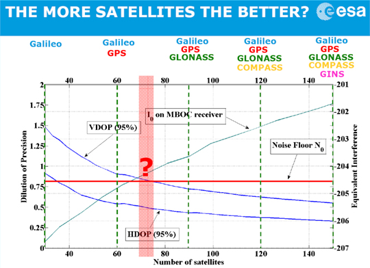
Günther Hein of the European Space Agency shows this remarkable diagram (Figure 1): as the number of systems increases and the number of satellites heads for that 150, up rises the noise they make, the blue-green line. More than about 70 of them, and satellite noise exceeds the cosmic noise floor in red and becomes the main source of noise. The more satellites, the worse the reception as GNSS interferes with itself. Too many satellites, and you’d pick up none at all! The first threat of the triple whammy is self-inflicted.
Chart: David Last and Sally Basker
Figure 1. The first threat of the Triple Whammy: new satellite systems. Source: Günther Hein.
The Second Threat
Conflicts between nations as their new GNSSs compete for radio spectrum also threaten GNSS viability.
The frequency bands available to satellite navigation are essentially L2, L5, and the principal one we use currently, L1. On L1, the European Galileo system and the Chinese Compass system occupy the same areas. Now, that’s very desirable if the two systems are to share receivers. But they also compete for that spectrum, and there is conflict between Compass and Galileo.
This battle for spectrum is a highly complex engineering problem. But chiefly, the spectrum wars are political, even emotional.
Chinese satellites fly across American skies broadcasting signals that interfere with European receivers. Spectrum wars have everything to do with relationships between nations and little to do with battles between engineers. They are developing into a classic tragedy of the commons: a situation in which self-interest determines how a limited resource — here the radio spectrum — is to be shared in a regime in which regulation is weak. The International Telecommunication Union sets standards and registers claims. The UN Office for Outer Space Affairs seeks to mediate. But neither is a policeman; sovereign governments may sometimes be penniless, but they are very powerful.
The second threat of the Triple Whammy is also self-inflicted.
The Third Threat
Communications systems compete with GNSS for spectrum: witness the current LightSquared case of a powerful new broadband system. For existing receivers, including those in government systems and aviation, it seems there is no fix for its devastating interference. LightSquared is driven by rich and powerful commercial forces; it could well win this fight.
Communication technologies will continue to press upon the satellite navigation spectrum. LightSquared will likely erode spectrum gaps between communications and navigation services, the so-called guard bands.
Satellite navigation has become highly political. The intense use of GNSS across our economies makes them vulnerable. GNSS is threatened by a Triple Whammy, by jamming, and by spoofing. These increase the risks to our security and our economies, both in probability and impact. The solution of detecting jammers and making ownership illegal will help with local problems in local areas. But the Triple Whammy threats are not local; they are national and international, world-wide.
Today’s spectrum wars affect us all. That the loss of GPS would increase the price of a loaf — the very trigger for the French Revolution — brings this down to earth.
These are not technical issues, they determine the price of our food! They constitute a real and present danger to our societies — down to the mundane yet very real level of our daily bread.
David Last is a past-president of the Royal Institute of Navigation, a consultant and expert witness on radio-navigation and communications systems to companies, governmental and international organizations, and criminal investigators.
Sally Basker, former director of research and radionavigation at the General Lighthouse Authorities of the UK and Ireland, has opened Traxis Ltd: management, business, and technology advice with expertise in navigation service provision. See www.traxis.co.uk.
This article is adapted from a presentation at the European Navigation Conference, London, November 2011. A longer version of the talk appears in the Royal institute of Navigation News.
GALILEO PROTOFLIGHTMODEL satellite began transmitting E1 and E5 signals in early December. ESA reports them well within power and shape specifications, and suited for interoperability with GPS.
The Galileo ProtoFlightModel (PFM) in-orbit validation (IOV) satellite GSAT0101 began transmitting E1 signals on December 10 using the E11 ranging code, and E5 signals early on December 14. Launched at the same time, Flight Model 2 (FM2), GSAT0102, has not yet started transmitting navigation signals. Several companies and laboratories around the world immediately began processing the PFM signals. This story briefly aggregates their reports.
The European Space Agency (ESA) proudly released a statement: “Europe’s Galileo system has passed its latest milestone, transmitting its very first test navigation signal back to Earth. [. . . . ] The turn of Galileo’s main L-band (1200-1600 MHz) antenna came on the early morning of Saturday 10 December. A test signal was transmitted by the first Galileo satellite in the E1 band, which will be used for Galileo’s Open Service once the system begins operating in 2014. [. . . . ]
“The signal power and shape was well within specifications. The shape is especially important because its modulation is carefully designed to enable interoperability with the L1 band of U.S. GPS navigation satellites: Galileo and GPS can indeed work together as planned.
“The test campaign is concentrating on the first satellite for the reminder of the year, with the focus moving to the second Galileo satellite from the start of 2012. The plan is to complete In-Orbit Testing by next spring.
“The next pair of Galileo In-Orbit Validation satellites will also be launched next year, to form the operational nucleus of the full Galileo constellation. Meanwhile the next batch of Galileo satellites are currently being manufactured for launch in 2014.”
Thales Avionics. Thales Avionics has developed a Galileo receiver capable of processing the Open Service, Commercial Service, and Safety of Life service of the Galileo constellation.
Figure 1 shows a screenshot of the Thales Avionics receiver interface program, highlighting the L1 signal energy (top right) and the pilot secondary code (bottom). The satellite Doppler and C/N0 values have been recorded and are provided in Figure 2.
Figure 1. Screen of Thales Avionics receiver interface highlighting L1 signal energy (top right) and the pilot secondary code (bottom). (Click to enlarge).
Figure 2. Satellite doppler and C/N0 values from the Thales Avionics receiver.
Thales has developed a coherent processing of the Galileo E5 AltBOC(15,10) signal compatible with hardware architecture designed for independent processing of both E5a and E5b. This processing is fully compatible with the mismatch between the two RF channels on E5a and E5b, thanks to real-time calibration based on satellite signals. This processing only requires software implementation, without additional recurrent costs. The technique is relevant for future receivers operating in the E5 band, in order to significantly enhance the accuracy, with respect to thermal noise and multi-path, and to improve the cycle slip probability.
CONGO. Several COoperative Network for GIOVE Observation (CONGO) stations, including one at the University of New Brunswick, are tracking both the E1 and E5 signals. Figure 3 shows C/N0 values collected at UNB.
Figure 3. C/N0 values in dB-Hz of PFM 1-Hz data collected at the University of New Brunswick, on December 10. Time axis runs for 24 hours starting at 01:00 UTC. Receiver is a Javad Delta-G2T. JAVAD GNSS. On December 12, JAVAD GNSS announced that it has tracked the Galileo in-orbit validation satellite, temporarily designated PRN-11.
“An important point is that we tracked it with our units that are already in the market,” said Javad Ashjaee, CEO. “This is not a lab tests. Our customers can track it too.”
Figure 4 shows the company’s tracking results of PRN-11: plots of pseudorange (in chips), doppler (in Hz), and SNR (relative number).
Figure 4. JAVAD GNSS tracking results of Galileo PRN-11 for now, plots of pseudorange (in chips), doppler (in Hz), and SNR (relative number).
Calgary PLAN Group. The University of Calgary sent a detailed report. (See Figure 5 and next item.)
Figure 5. Raw correlator values for the E1 B/C, E5aI/Q and E5bI/Q signals. The bit periods can be clearly seen on E1B, E5aI and E5bI. The secondary code can be observed on E1C while the pilot signal can be seen on singals E5aQ and E5bQ. (From the Calgary Report.)
Galileo E1 and E5: the Calgary Report
By James T. Curran and Aiden Morrison
Researchers in the Position, Location and Navigation (PLAN) Group at the University of Calgary recorded E1 and E5 data using a single dual-channel front-end and subsequently acquired and tracked E1 B/C, E5a and E5b signals in the early morning of December 15.
Using a dual channel front-end designed in-house, a Novatel GPS-703-GGG antenna and a laptop computer, IF data was collected to examine these new signals. This data was processed by GSNRx, a reconfigurable a multi-system, multi-frequency software receiver developed by the PLAN Group.
At approximately 03:20 MST (UTC – 7:00) more than 20 GNSS satellites were visible from a rooftop mounted antenna. Having reconfigured the front-end to accommodate the E5 band, IF data was collected which included Galileo E1 B/C and E5 A/B, GIOVE-B E1 B/C and E5a, GPS L1 C/A and L5, and GLONASS L1 C/A. Following some last-minute modifications to GSNRx to include the Galileo E5b signals, the samples were processed, simultaneously tracking GPS and Galileo on both the L1/E1 and L5/E5 frequencies and GLONASS on L1.
A subset of the raw correlator values for the E1 B, E1 C, E5a I and E5a Q signals are shown in Figure 5 above. Note that the E1 C values have been offset by -2.0×10⁵ for clarity. A data-rate of 250 symbol/s is clearly visible on the E1 B and E5b signals while a 50 symbol/s stream can be observed on the E5a I signal. The 25 chip secondary code is also evident on E1 C at a rate of 250 chip/s.
All six components of the Galileo-PFM signals shown above (transmitted on PRN 11) were tracked independently and their signal modulations were found to agree with the Galileo Open Service ICD. A trace of the measured carrier-to-noise floor ratios for the Galileo signals is shown in Figure 6. As indicated by the ICD, the E5b signals were observed at 2 dB lower power than the E1 B and C signals. The E5a signals, however, were expected to be received at the same power as E5b and yet were observed at approximately 4 dB lower power. This is believed to be a combination of the antenna and IF filtering within the front-end as the E5a center frequency is located relatively near the pass-band edge of both. This front-end was initially designed for 40 MHz bandwidth, but used in this experiment at 50 MHz, as will be discussed later.
Figure 6. C/N0 for Galileo-PFM signals.
The software receiver was once again reconfigured, this time to produce signal correlator values spaced along a delay of approximately 700 m and 70 m for the E1 A/B and E5 A/B signals, respectively, such that the cross-correlation of the received and local-replica PRN sequences could be examined. The signals were tracked for 10 seconds and the 1 ms correlator values averaged, to produce estimates of the code cross-correlation function. The characteristic ripple of the CBOC modulation on E1 B/C can be seen in Figure 7 (left), particularly on the right-most ascending feature of the envelope. Likewise, the alt-BOC cross-correlation of E5a Q in Figure 7 (right) is as expected. It is noted that the E5a I signal has suffered some distortion due to the filtering effects mentioned above.
Figure 7. Measured cross-correlation functions for the Galileo PFM E1 B and C signals (left) and E5a I and E5b I signals (right).
For details of the PLAN group’s front-end, a flexible GNSS signal capture tool, and other specifics on the process employed, see the full-length article.
GPS III Testbed Sat Delivered
Lockheed Martin delivered the the GPS III Non-Flight Satellite Testbed (GNST), the program’s pathfinder spacecraft, to its Denver-area facility. The pathfinder will now undergo final assembly, integration, and test activities.
The GNST is a full-sized, flight equivalent prototype of a GPS III satellite used to identify and solve development issues prior to integration and test of the first space vehicle. According to the company, the approach reduces risk, improves production predictability, increases mission assurance and lowers overall program costs. In Denver, the GNST will be mated with its core structure, navigation payload, and antenna elements before completing pathfinding activities and checkout of environmental test facilities. The GNST will then be shipped to Cape Canaveral Air Force Station, Fla., for pathfinding activities at the launch site.
GPS III satellites, when launched as scheduled to being in 2014, will replace aging on-orbit GPS satellites to deliver better accuracy and improved anti-jamming power, while enhancing spacecraft design life and adding a new civil signal designed to be interoperable with international global navigation satellite systems.
In parallel with the GNST, progress on the first space vehicle is progressing on schedule. Lockheed Martin received the core structure for the first GPS III satellite in Stennis, Mississippi, on August 4, and is now integrating the space vehicle’s flight propulsion subsystem. The integrated core propulsion module will be shipped to the GPF in the summer of 2012 and will then undergo final assembly, integration and test in order to meet its planned 2014 launch.
The GPS III team is led by the GPS Directorate at the U.S. Air Force Space and Missile Systems Center. Lockheed Martin is the GPS III prime contractor with teammates ITT, General Dynamics, Infinity Systems Engineering, Honeywell, ATK and other subcontractors.
Drone Downed
Press reports speculate that GPS spoofing was used to get the RQ-170 Sentinel Drone to land in Iran. According to an Iranian engineer quoted in a Christian Science Monitor story, “By putting noise [jamming] on the communications, you force the bird into autopilot. This is where the bird loses its brain.” At that point, the drone relies on GPS signals to get home. By spoofing GPS, Iranian engineers were able to get the drone to “land on its own where we wanted it to, without having to crack the remote-control signals and communications.”
“The GPS navigation is the weakest point,” the Iranian engineer told the Monitor, giving a detailed description of Iran’s electronic ambush of the highly classified pilotless aircraft.
In 2011, the U.S. Air Force awarded two $47 million contracts to BAE Systems and Northrop Grumman for development of a navigation warfare sensor to replace military GPS receivers on aircraft and missiles, and designed to maintain freedom of action under extreme GPS countermeasures.
GLONASS Fully Operational
For the first time in more than 15 years, GLONASS is fully operational, with 24 satellites in their designated orbital slots, set healthy, and providing world coverage.
GLONASS 744, an M-class satellite and one of three launched from Baikonur on 4 November, was set healthy December 8, bringing the number of healthy operating satellites to the full complement of 24.
GLONASS briefly achieved a 24-satellite constellation in early 1996 but it degraded rapidly due to Russia’s economic difficulties following the break-up of the Soviet Union coupled with the short lifetime of the GLONASS satellites. Since 2002, the GLONASS constellation has slowly but surely been rebuilt with the Russian government’s commitment to provide a global positioning and navigation system comparable to that of GPS.
Luch SBAS. Roscosmos also launched the Luch-5A geostationary relay satellite on December 11.
Luch-5A is the first in a series of new data relay satellites designed to rebuild the Luch Multifunctional Space Relay System, which had ceased operating by 1998. Among other functions, 5A hosts a wideband satellite-based augmentation system (SBAS) transponder.
The SBAS transponder will transmit correction and integrity data for GLONASS and GPS on the GPS L1 frequency with a C/A pseudorandom noise code to be assigned by the GPS Directorate. The data will be provided by the System for Differential Correction and Monitoring or SDCM, which uses a ground network of monitoring stations on Russian territory as well as some overseas stations.
As the SDCM primary service area is Russian territory, the main lobe of the SBAS antenna beam will be directed to the north with an angle of 7 degrees relative to the direction to the equator. Transmitted power of 60 watts will give a signal power level at Earth’s surface roughly equal to that of GLONASS and GPS signals, about –158 dBW.
The current international SBAS data format has a limited capability for broadcasting corrections for both GLONASS and GPS satellites combined. There is space for only 51 satellites, insufficient for the current number of satellites on orbit. As a result, studies are being carried out in an attempt to resolve this problem. One option is to use a dynamic satellite mask, where an SDCM satellite would only broadcast corrections and integrity data for those GLONASS and GPS satellites in view of users in the territory of the Russian Federation.
Luch-5A is the first of three MSRS/SDCM satellites. Luch-5B will be launched in 2012 into a slot at 95 degrees east longitude and Luch-4, in 2014, into a slot at 167 degrees east longitude.
Beidou Launch Fills Regional Nav System
The Beidou-2/Compass IGSO-5 (fifth inclined geosynchonous orbit) satellite was launched on December. According to a Chinese government announcement, this launch completes the construction of the basic regional navigation system for service to China and will be operational by the end of the year. However, completion of the Phase II development, to provide service to the Asia/Pacific region, will require further satellite launches in 2012. Phase III global coverage, with a 30-satellite system, will be achieved by 2020 according to the Beidou website.
The GNSS community outside China still awaits a Compass interface control document (ICD), which has been promised by the end of 2012.
LightSquared Incompatibility Declared
U.S. government tests conducted in November showed that 75 percent of GPS receivers examined were interfered with at a distance of 100 meters from a LightSquared (LS)base station. The report states that “No additional testing is required to confirm harmful interference exists,” and “Immediate use of satellite service spectrum for terrestrial service not viable because of system engineering and integration challenges.”
The tests showed interference by the LS Low 10 terrestrial signal with an overwhelming majority of general-purpose GPS receivers. Data from LS handsets was collected, analysis is underway, but no results were given. Wideband and military receivers were tested, but neither specifications nor results were presented; a classified session was convened for that purpose.
Of the 92 receivers for which full data sets were compiled, 75 percent of them failed a 1db test, showing harmful interference at 100 meters from a LS base station. These 69 receivers failed at a broadcast level of around -15dBm from the LS transmitter.
In a December 7 filing with the FCC, LightSquared further revised its public plans to say that it would “limit its power on the ground when transmitting in the lower 10 MHz from 1526-1536 MHz to no more than –30 dBm until January 1, 2015, –27 dBm until January 1, 2017, and –24 dBm thereafter.” According to test data, at –30 dBm, approximately 17 percent of GPS receivers would be disrupted; at –27 dBm, 25 percent; at –24 dBm, 36 percent. Proceeding with this scenario would require the assumption that the FCC, or indeed anyone, believes anything that LightSquared says at any given instant, for any given duration.
By Kyle Wesson, Daniel Shepard, and Todd Humphreys
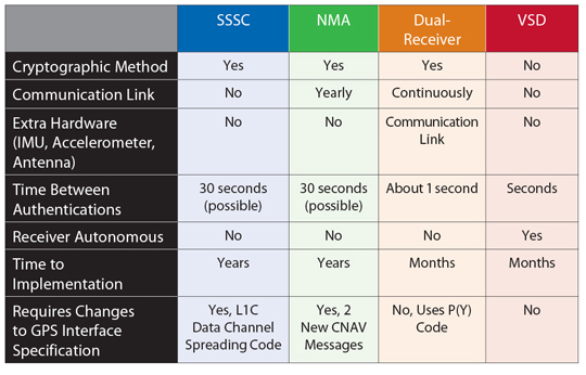
Disruption created by intentional generation of fake GPS signals could have serious economic consequences. This article discusses how typical civil GPS receivers respond to an advanced civil GPS spoofing attack, and four techniques to counter such attacks: spread-spectrum security codes, navigation message authentication, dual-receiver correlation of military signals, and vestigial signal defense. Unfortunately, any kind of anti-spoofing, however necessary, is a tough sell.
GPS spoofing has become a hot topic. At the 2011 Institute of Navigation (ION) GNSS conference, 18 papers discussed spoofing, compared with the same number over the past decade. ION-GNSS also featured its first panel session on anti-spoofing, called “Improving Security of GNSS Receivers,” which offered six security experts a forum to debate the most promising anti-spoofing technologies.
The spoofing threat has also drawn renewed U.S. government scrutiny since the initial findings of the 2001 Volpe Report. In November 2010, the U.S. Position Navigation and Timing National Executive Committee requested that the U.S. Department of Homeland Security (DHS) conduct a comprehensive risk assessment on the use of civil GPS. In February 2011, the DHS Homeland Infrastructure Threat and Risk Analysis Center began its investigation in conjunction with subject-matter experts in academia, finance, power, and telecommunications, among others. Their findings will be summarized in two forthcoming reports, one on the spoofing and jamming threat and the other on possible mitigation techniques. The reports are anticipated to show that GPS disruption due to spoofing or jamming could have serious economic consequences.
Effective techniques exist to defend receivers against spoofing attacks. This article summarizes state-of-the-art anti-spoofing techniques and suggests a path forward to equip civil GPS receivers with these defenses. We start with an analysis of a typical civil GPS receiver’s response to our laboratory’s powerful spoofing device. This will illustrate the range of freedom a spoofer has when commandeering a victim receiver’s tracking loops. We will then provide an overview of promising cryptographic and non-cryptographic anti-spoofing techniques and highlight the obstacles that impede their widespread adoption.
The Spoofing Threat
Spoofing is the transmission of matched-GPS-signal-structure interference in an attempt to commandeer the tracking loops of a victim receiver and thereby manipulate the receiver’s timing or navigation solution. A spoofer can transmit its counterfeit signals from a stand-off distance of several hundred meters or it can be co-located with its victim.
Spoofing attacks can be classified as simple, intermediate, or sophisticated in terms of their effectiveness and subtlety. In 2003, the Vulnerability Assessment Team at Argonne National Laboratory carried off a successful simple attack in which they programmed a GPS signal simulator to broadcast high-powered counterfeit GPS signals toward a victim receiver. Although such a simple attack is easy to mount, the equipment is expensive, and the attack is readily detected because the counterfeit signals are not synchronized to their authentic counterparts.
In an intermediate spoofing attack, a spoofer synchronizes its counterfeit signals with the authentic GPS signals so they are code-phase-aligned at the target receiver. This method requires a spoofer to determine the position and velocity of the victim receiver, but it affords the spoofer a serious advantage: the attack is difficult to detect and mitigate.
The sophisticated attack involves a network of coordinated intermediate-type spoofers that replicate not only the content and mutual alignment of visible GPS signals but also their spatial distribution, thus fooling even multi-antenna spoofing defenses.
Table 1. Comparison of anti-spoofing techniques discussed in this article.
Lab Attack. So far, no open literature has reported development or research into the sophisticated attack. This is likely because of the success of the intermediate-type attack: to date, no civil GPS receiver tested in our laboratory has fended off an intermediate-type spoofing attack. The spoofing attacks, which are always conducted via coaxial cable or in radio-frequency test enclosures, are performed with our laboratory’s receiver-spoofer, an advanced version of the one introduced at the 2008 ION-GNSS conference (see “Assessing the Spoofing Threat,” GPS World, January 2009).
To commence the attack, the spoofer transmits its counterfeit signals in code-phase alignment with the authentic signals but at power level below the noise floor. The spoofer then increases the power of the spoofed signals so that they are slightly greater than the power of the authentic signals. At this point, the spoofer has taken control of the victim receiver’s tracking loops and can slowly lead the spoofed signals away from the authentic signals, carrying the receiver’s tracking loops with it. Once the spoofed signals have moved more than 600 meters in position or 2 microseconds in time away from the authentic signals, the receiver can be considered completely owned by the spoofer.
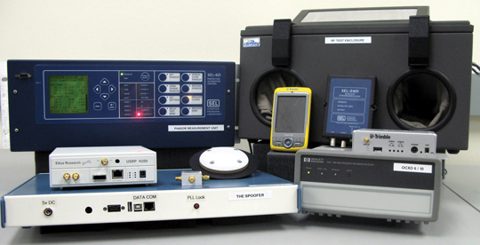
Spoofing testbed at the University of Texas Radionavigation Laboratory, an advanced and powerful suite for anti-spoofing research. On the right are several of the civil GPS receivers tested and the radio-frequency test enclosure, and on the left are the phasor measurement unit and the civil GPS spoofer.
Although our spoofer fooled all of the receivers tested in our laboratory, there are significant differences between receivers’ dynamic responses to spoofing attacks. It is important to understand the types of dynamics that a spoofer can induce in a target receiver to gain insight into the actual dangers that a spoofing attack poses rather than rely on unrealistic assumptions or models of a spoofing attack. For example, a recent paper on time-stamp manipulation of the U.S. power grid assumed that there was no limit to the rate of change that a spoofer could impose on a victim receiver’s position and timing solution, which led to unrealistic conclusions.
Experiments performed in our laboratory sought to answer three specific questions regarding spoofer-induced dynamics:
How quickly can a timing or position bias be introduced?
What kinds of oscillations can a spoofer cause in a receiver’s position and timing?
How different are receiver responses to spoofing?
These questions were answered by determining the maximum spoofer-induced pseudorange acceleration that can be used to reach a certain final velocity when starting from a velocity of zero, without raising any alarms or causing the target receiver to lose satellite lock. The curve in the velocity-acceleration plane created by connecting these points defines the upper bound of a region within which the spoofer can safely manipulate the target receiver. These data points can be obtained empirically and fit to an exponential curve. Alarms on the receiver may cause some deviations from this curve depending on the particular receiver.
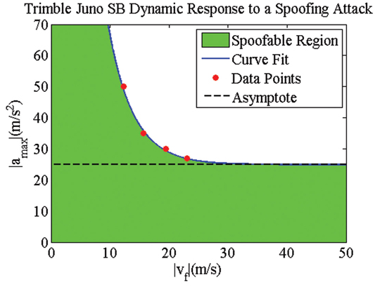
Figure 1 shows an example of the velocity-acceleration curve for a high-quality handheld receiver, whose position and timing solution can be manipulated quite aggressively during a spoofing attack. These results suggest that the receiver’s robustness — its ability to provide navigation and timing solutions despite extreme signal dynamics — is actually a liability in regard to spoofing. The receiver’s ability to track high accelerations and velocities allows a spoofer to aggressively manipulate its navigation solution.
Figure 1. Theoretical and experimental test results for a high-quality handheld receiver’s dynamic response to a spoofing attack. Although not shown here, the maximum attainable velocity is around 1,300 meters/second.
The relative ease with which a spoofer can manipulate some GPS receivers suggests that GPS-dependent infrastructure is vulnerable. For example, the telecommunications network and the power grid both rely on GPS time-reference receivers for accurate timing. Our laboratory has performed tests on such receivers to determine the disruptions that a successful spoofing attack could cause. The remainder of this section highlights threats to these two sectors of critical national infrastructure.
Cell-Phone Vulnerability. Code division multiple access (CDMA) cell-phone towers rely on GPS timing for tower-to-tower synchronization. Synchronization prevents towers from interfering with one another and enables call hand-off between towers. If a particular tower’s time estimate deviates more than 10 microseconds from GPS time, hand-off to and from that tower is disrupted. Our tests indicate that a spoofer could induce a 10-microsecond time deviation within about 30 minutes for a typical CDMA tower setup. A spoofer, or spoofer network, could also cause multiple neighboring towers to interfere with one another. This is possible because CDMA cell-phone towers all use the same spreading code and distinguish themselves only by the phasing (that is, time offset) of their spreading codes. Furthermore, it appears that a spoofer could impair CDMA-based E911 user-location.
Power-Grid Vulnerability. Like the cellular network, the power grid of the future will rely on accurate GPS time-stamps. The efficiency of power distribution across the grid can be improved with real-time measurements of the voltage and current phasors. Phasor measurement units (PMUs) have been proposed as a smart-grid technology for precisely this purpose. PMUs rely on GPS to time-stamp their measurements, which are sent back to a central monitoring station for processing. Currently, PMUs are used for closed-loop grid control in only a few applications, but power-grid modernization efforts will likely rely more heavily on PMUs for control. If a spoofer manipulates a PMU’s time stamps, it could cause spurious variations in measured phase angles. These variations could distort power flow or stability estimates in such a way that grid operators would take incorrect or unnecessary control actions including powering up or shutting down generators, potentially causing blackouts or damage to power-grid equipment.
Under normal circumstances, a changing separation in the phase angle between two PMUs indicates changes in power flow between the regions measured by each PMU. Tests demonstrate that a spoofer could cause variations in a PMU’s measured voltage phase angle at a rate of 1.73 degrees per minute. Thus, a spoofing attack could create the false indications of power flow across the grid. The tests results also reveal, however, that it is impossible for a spoofer to cause changes in small-signal grid stability estimates, which would require the spoofer to induce rapid (for example, 0.1–3 Hz) microsecond-amplitude oscillations in timing. Such oscillations correspond to spoofing dynamics well outside the region of freedom of all receivers we have tested. A spoofer might also be able to affect fault-location estimates obtained through time-difference-of-arrival techniques using PMU measurements. This could cause large errors in fault-location estimates and hamper repair efforts.
What Can Be Done? Despite the success of the intermediate-type spoofing attack against a wide variety of civil GPS receivers and the known vulnerabilities of GPS-dependent critical infrastructure to spoofing attacks, anti-spoofing techniques exist that would enable receivers to successfully defend themselves against such attacks. We now turn to four promising anti-spoofing techniques.
Cryptographic Methods
These techniques enable a receiver to differentiate authentic GPS signals from counterfeit signals with high likelihood. Cryptographic strategies rely on the unpredictability of so-called security codes that modulate the GPS signal. An unpredictable code forces a spoofer who wishes to mount a successful spoofing attack to either
estimate the unpredictable chips on-the-fly, or
record and play back authentic GPS spectrum (a meaconing attack).
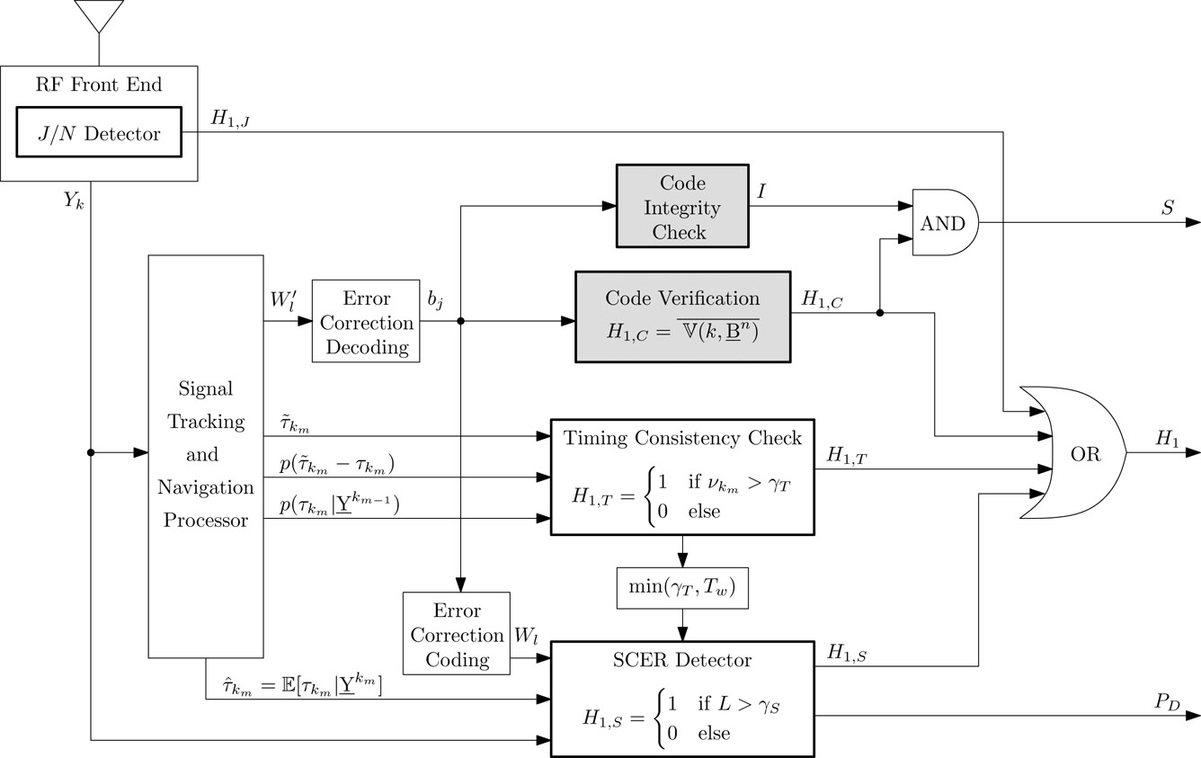
To avoid unrealistic expectations, it should be noted that no anti-spoofing technique is completely impervious to spoofing. GPS signal authentication is inherently probabilistic, even when rooted in cryptography. Many separate detectors and cross-checks, each with its own probability of false alarm, are involved in cryptographic spoofing detection. Figure 2 illustrates how the jammer-to-noise ratio detector, timing consistency check, security-code estimation and replay attack (SCER) detector, and cryptographic verification block all work together. This hybrid combination of statistical hypothesis tests and Boolean logic demonstrates the complexities and subtleties behind a comprehensive, probabilistic GPS signal authentication strategy for security-enhanced signals.
Figure 2. GNSS receiver components required for GNSS signal authentication. Components that support code origin authentication are outlined in bold and have a gray fill, whereas components that support code timing authentication are outlined in bold and have no fill. The schematic assumes a security code based on navigation message authentication.
Spread Spectrum Security Codes. In 2003, Logan Scott proposed a cryptographic anti-spoofing technique based on spread spectrum security codes (SSSCs). The most recent proposed version of this technique targets the L1C signal, which will be broadcast on GPS Block III satellites, because the L1C waveform is not yet finalized. Unpredictable SSSCs could be interleaved with the L1C spreading code on the L1C data channel, as illustrated in Figure 3. Since L1C acquisition and tracking occurs on the pilot channel, the presence of the SSSCs has negligible impact on receivers. Once tracking L1C, a receiver can predict when the next SSSC will be broadcast but not its exact sequence. Upon reception of an SSSC, the receiver stores the front-end samples corresponding to the SSSC interval in memory. Sometime later, the cryptographic digital key that generated the SSSC is transmitted over the navigation message. With knowledge of the digital key, the receiver generates a copy of the actual transmitted SSSC and correlates it with the previously-recorded digital samples. Spoofing is declared if the correlation power falls below a pre-determined threshold.
Figure 3. Placement of the periodically unpredictable spread spectrum security codes in the GPS L1C data channel spreading sequence.
When the security-code chip interval is short (high chipping rate), it is difficult for a spoofer to estimate and replay the security code in real time. Thus, the SSSC technique on L1C offers a strong spoofing defense since the L1C chipping rate is high (that is, 1.023 MChips/second). Furthermore, the SSSC technique does not rely on the receiver obtaining additional information from a side channel; all the relevant codes and keys are broadcast over the secured GPS signals. Of course a disadvantage for SSSC is that it requires a fairly fundamental change to the currently-proposed L1C definition: the L1C spreading codes must be altered.
Implementation of the SSSC technique faces long odds, partly because it is late in the L1C planning schedule to introduce a change to the spreading codes. Nonetheless, in September 2011, Logan Scott and Phillip Ward advocated for SSSC at the Public Interface Control Working Group meeting, passing the first of many wickets. The proposal and associated Request for Change document will now proceed to the Lower Level GPS Engineering Requirements Branch for further technical review. If approved there, it passes to the Joint Change Review Board for additional review and, if again approved, to the Technical Interchange Meeting for further consideration. The chances that the SSSC proposal will survive this gauntlet would be much improved if some government agency made a formal request to the GPS Directorate to include SSSCs in L1C — and provided the funding to do so. The DHS seems to us a logical sponsoring agency.
Navigation Message Authentication. If an L1C SSSC implementation proves unworkable, an alternative, less-invasive cryptographic authentication scheme based on navigation message authentication (NMA) represents a strong fall-back option. In the same 2003 ION-GNSS paper that he proposed SSSC, Logan Scott also proposed NMA. His paper was preceded by an internal study at MITRE and followed by other publications in the open literature, all of which found merit in the NMA approach. The NMA technique embeds public-key digital signatures into the flexible GPS civil navigation (CNAV) message, which offers a convenient conveyance for such signatures. The CNAV format was designed to be extensible so that new messages can be defined within the framework of the GPS Interference Specification (IS). The current GPS IS defines only 15 of 64 CNAV messages, reserving the undefined 49 CNAV messages for future use.
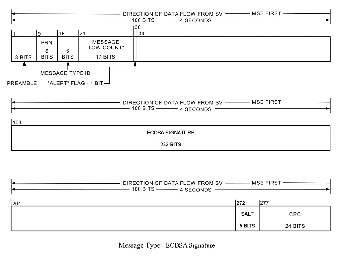
Our lab recently demonstrated that NMA works to authenticate not only the navigation message but also the underlying signal. In other words, NMA can be the basis of comprehensive signal authentication. We have proposed a specific implementation of NMA that is packaged for immediate adoption. Our proposal defines two new CNAV messages that deliver a standardized public-key elliptic-curve digital algorithm (ECDSA) signature via the message format in Figure 4.
Figure 4. Format of the proposed CNAV ECDSA signature message, which delivers the first or second half of the 466-bit ECDSA signature and a 5-bit salt in the 238-bit payload field.
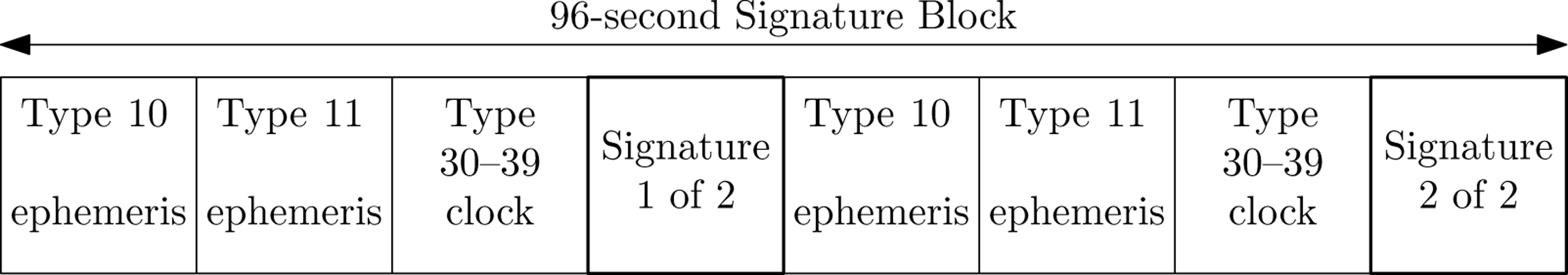
Although the CNAV message format is flexible, it is not without constraints. The shortest block of data in which a complete signature can be embedded is a 96-second signature block such as the one shown in Figure 5. In this structure, the two CNAV signature messages are interleaved between the ephemeris and clock data to meet the broadcast requirements.
Figure 5. The shortest broadcast signature block that does not violate the CNAV ephemeris and timing broadcast requirements. To meet the required broadcast interval of 48 seconds for message types 10, 11, and one of 30–39, the ECDSA signature is broadcast over a 96-second signature block that is composed of eight CNAV messages.
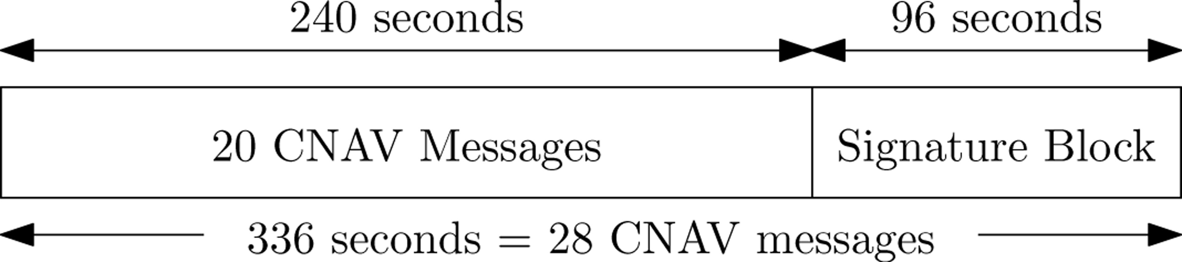
The choice of the duration between signature blocks is a tradeoff between offering frequent authentication and maintaining a low percentage of the CNAV message reserved for the digital signature. In our proposal, signature blocks are transmitted roughly every five minutes (Figure 6) so that only 7.5 percent of the navigation message is devoted to the digital signature. Across the GPS constellation, the signature block could be offset so that a receiver could authenticate at least one channel approximately every 30 seconds. Like SSSC, our proposed version of NMA does not require a receiver’s getting additional information from a side channel, provided the receiver obtains public key updates on a yearly basis.
Figure 6. A signed 336-second broadcast. The proposed strategy signs every 28 CNAV messages with a signature broadcast over two CNAV messages on each broadcast channel.
NMA is inherently less secure than SSSC. A NMA security code chip interval (that is, 20 milliseconds) is longer than a SSSC chip interval, thereby allowing the spoofer more time to estimate the digital signature on-the-fly. That is not to say, however, that NMA is ineffective. In fact, tests with our laboratory’s spoofing testbed demonstrated the NMA-based signal authentication structure described earlier offered a receiver a better-than 95 percent probability of detecting a spoofing attack for a 0.01 percent probability of false alarm under a challenging spoofing-attack scenario.
NMA is best viewed as a hedge. If the SSSC approach does not gain traction, then NMA might, since it only requires defining two new CNAV messages in the GPS IS — a relatively minor modification. CNAV-based NMA could defend receivers tracking L2C and L5. A new CNAV2 message will eventually be broadcast on L1 via L1C, so a repackaged CNAV2-based NMA technique could offer even single-frequency L1 receivers a signal-side anti-spoofing defense.
P(Y) Code Dual-Receiver Correlation. This approach avoids entirely the issue of GPS IS modifications. The technique correlates the unknown encrypted military P(Y) code between two civil GPS receivers, exploiting known carrier-phase and code-phase relationships. It is similar to the dual-frequency codeless and semi-codeless techniques that civil GPS receivers apply to track the P(Y) code on L2. Peter Levin and others filed a patent on the codeless-based signal authentication technique in 2008; Mark Psiaki extended the approach to semicodeless correlation and narrow-band receivers in a 2011 ION-GNSS paper.
In the dual-receiver technique, one receiver, stationed in a secure location, tracks the authentic L1 C/A codes while receiving the encrypted P(Y) code. The secure receiver exploits the known timing and phase relationships between the C/A code and P(Y) code to isolate the P(Y) code, of which it sends raw samples (codeless technique) or estimates of the encrypting W-code chips (semi-codeless technique) over a secure network to the defending receiver. The defending receiver correlates its locally-extracted P(Y) with the samples or W-code estimates from the secure receiver. If a spoofing attack is underway, the correlation power will drop below a statistical threshold, thereby causing the defending receiver to declare a spoofing attack. Although the P(Y) code is 20 MHz wide, a narrowband civil GPS receiver with 2.6 MHz bandwidth can still perform the statistical hypothesis tests even with the resulting 5.5 dB attenuation of the P(Y) code. Because the dual-receiver method can run continuously in the background as part of a receiver’s standard GPS signal processing, it can declare a spoofing attack within seconds — a valuable feature for many applications.
Two considerations about the dual-receiver technique are worth noting. First, the secure receiver must be protected from spoofing for the technique to succeed. Second, the technique requires a secure communication link between the two receivers. Although the first requirement is easily achieved by locating secure receivers in secure locations, the second requirement makes the technique impractical for some applications that cannot support a continuous communication link.
Of all the proposed cryptographic anti-spoofing techniques, only the dual-receiver method could be implemented today. Unfortunately the P(Y) code will no longer exist after 2021, meaning that systems that make use of the P(Y)-based dual-receiver technique will be rendered unprotected, although a similar M-code-based technique could be an effective replacement. The dual-receiver method, therefore, is best thought of as a stop-gap: it can provide civil GPS receivers with an effective anti-spoofing technique today until a signal-side civil GPS authentication technique is approved and implemented in the future This sentiment was the consensus of the panel experts at the 2011 ION-GNSS session on civil GPS receiver security.
Non-Cryptographic Methods
Non-cryptographic techniques are enticing because they can be made receiver-autonomous, requiring neither security-enhanced civil GPS signals nor a side-channel communication link. The literature contains a number of proposed non-cryptographic anti-spoofing techniques. Frequently, however, these techniques rely on additional hardware, such as accelerometers or inertial measurements units, which may exceed the cost, size, or weight requirements in many applications. This motivates research to develop software-based, receiver-autonomous anti-spoofing methods.
Vestigial Signal Defense (VSD). This software-based, receiver-autonomous anti-spoofing technique relies on the difficulty of suppressing the true GPS signal during a spoofing attack. Unless the spoofer generates a phase-aligned nulling signal at the phase center of the victim GPS receiver’s antenna, a vestige of the authentic signal remains and manifests as a distortion of the complex correlation function. VSD monitors distortion in the complex correlation domain to determine if a spoofing attack is underway.
To be an effective defense, the VSD must overcome a significant challenge: it must distinguish between spoofing and multipath. The interaction of the authentic and spoofed GPS signals is similar to the interaction of direct-path and multipath GPS signals. Our most recent work on the VSD suggests that differentiating spoofing from multipath is enough of a challenge that the goal of the VSD should only be to reduce the degrees-of-freedom available to a spoofer, forcing the spoofer to act in a way that makes the spoofing signal or vestige of the authentic GPS signal mimic multipath. In other words, the VSD seeks to corner the spoofer and reduce its space of possible dynamics.
Among other options, two potential effective VSD techniques are
a maximum-likelihood bistatic-radar-based approach and
a phase-pseudorange consistency check.
The first approach examines the spatial and temporal consistency of the received signals to detect inconsistencies between the instantaneous received multipath and the typical multipath background environment. The second approach, which is similar to receiver autonomous integrity monitoring (RAIM) techniques, monitors phase and pseudorange observables to detect inconsistencies potentially caused by spoofing. Again, a spoofer can act like multipath to avoid detection, but this means that the VSD would have achieved its modest goal.
Anti-Spoofing Reality Check
Security is a tough sell. Although promising anti-spoofing techniques exist, the reality is that no anti-spoofing techniques currently defend civil GPS receivers. All anti-spoofing techniques face hurdles. A primary challenge for any technique that proposes modifying current or proposed GPS signals is the tremendous inertia behind GPS signal definitions. Given the several review boards whose approval an SSSC or NMA approach would have to gain, the most feasible near-term cryptographic anti-spoofing technique is the dual-receiver method. A receiver-autonomous, non-cryptographic approach, such as the VSD, also warrants further development. But ultimately, the SSSC or NMA techniques should be implemented: a signal-side civil GPS cryptographic anti-spoofing technique would be of great benefit in protecting civil GPS receivers from spoofing attacks.
Manufacturers
The high-quality handheld receiver cited in Figure 1 was a Trimble Juno SB. Testbed equipment shown: Schweitzer Engineering Laboratories SEL-421 synchrophasor measurement unit; Ramsey STE 3000 radio-frequency test chamber; Ettus Research USRP N200 universal software radio peripheral; Schweitzer SEL-2401 satellite-synchronized clock (blue); Trimble Resolution SMT receiver (silver); HP GPS time and frequency reference receiver.
Full results of Figure 1 experiment are given in Shepard, D.P. and T.E. Humphreys, “Characterization of Receiver Response to Spoofing Attacks,” Proceedings of ION-GNSS 2011.
NMA can be the basis of comprehensive signal authentication: Wesson, K.D., M. Rothlisberger, T. E. Humphreys (2011), “Practical cryptographic civil GPS signal authentication,” Navigation, Journal of the ION, submitted for review.
Kyle Wesson is pursuing his M.S. and Ph.D. degrees in electrical and computer engineering at the University of Texas at Austin. He is a member of the Radionavigation Laboratory. He received his B.S. from Cornell University.
Daniel Shepard is pursuing his M.S. and Ph.D. degrees in aerospace engineering at the University of Texas at Austin, where he also received his B.S. He is a member of the Radionavigation Laboratory.
Todd Humphreys is an assistant professor in the department of Aerospace Engineering and Engineering Mechanics at the University of Texas at Austin and director of the Radionavigation Laboratory. He received a Ph.D. in aerospace engineering from Cornell University.
Consider two notable developments in 2011 that will influence the development of consumer transportation:
China became the largest manufacturer of automobiles, producing more than 18 million vehicles, easily overtaking Europe and North America.
Smartphone volume shipments surpassed the volume of laptops and desktop PCs combined.
Reflecting these two rising economic rockets, the November Munich Telematics show drew its largest attendance yet, 500-plus participants, and a greatly expanded exhibit area.
The rising dominance of smartphones — one participant observed that they are taking over the world —will have a big impact on how users expect to access or view their telematics data; that is, any wireless information accessed by them while in their car. Developers and manufactures used to have a problem regarding which system to support, but with Android now at more than 50 percent of smartphones share, it is becoming the de facto first-choice standard and will probably become the user interface model.
eCall. Also in 2011, the European Union finally mandated eCall, the emergency call system in automobiles that sends vehicle position to emergency services after a crash. Unfortunately, the mandate is for 2015. I guess this gives them a chance to use the European satnav system Galileo, which hopefully may have something to offer hopefully by then.
This year the Russians leapfrogged the Western Europeans and mandated their own version of eCall, known as ERA, for 2013. It will use GLONASS, the Russian satnav system, which unlike Galileo is operational now. Of course, GPS is still employed, and the real benefit today is using GLONASS plus GPS in a multi-constellation fix mode for higher reliability especially in urban areas compared to GPS alone.
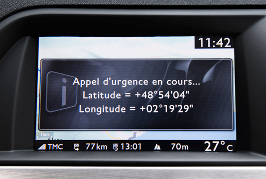
Emergency call in progress, triggered by SOS button in PSA Peugeot Citroen’s roof panel (bottom photo).
At the Munich Telematics show it was clear that the Russian mandate has put wind into the telematics emergency call market’s sails. From the Russian company Cesar’s presentation, we learned that following road accidents in Russia, 14 percent of car occupants die, compared to 2 percent in the United States. Getting emergency support to the scene more quickly is critical to reducing fatalities, and on this basis Russia has got some catching up to do.
You would think that everyone would be rushing to get more safety, and as one market research presenter said, it comes high on the user wish list. Another presenter stated that while people may desire it, they seem reluctant to pay for it at first. As an historical example, initially when people had the option of paying for airbags as an extra, it was practically never taken as an option. Now it is standard in all cars for drivers and passengers.Think about it — would you now buy a car without an airbag?
PSA Peugeot Citroen, the big French car company, shows the way with a version of eCall in their cars that doesn’t lose money! There is a big debate about who gets called when a crash happens. Is it the public service access points (PSAPs) or third-party services (TPS). Peugeot favours the TPS model, which can filter the more common breakdown and false alarms from true crash calls to be forwarded to the emergency services at PSAPs. While eCall initially favoured PSAP, the trend seems to support Peugeot’s decision and TPS.
The PSA eCall also does not support the so-called in-band modem, which allows crash-position data to be sent over a voice call on the eCall box by encoding the data into a speech-like signal. The modem theory is, you need to keep the voice call open to keep talking to the person in the automobile. According to PSA, apart from the issue of patents with the in-band modem, it seems that 30 percent of the data is lost, and 40 percent of the PSAPs in Germany cannot handle it.
GPRS is the best way of sending crash-position data with SMS text message as a back-up. As for voice, most people get out of their car after an accident and do not speak on the eCall box. I guess if people are unconscious and are not able to get out of the car, they won’t speak either.
While smartphones dominate in many areas, they have been ruled out for eCall safety apps in cars, as no one can guarantee a smartphone will work after an accident. As for crash detection, that can only work if a device is bolted down to the car frame. Only that way can you sense the high-G forces during a crash.
Insurance. Until the mandates kick in for eCall/ERA, you can understand why an automobile manufacturer’s marketing imagery does not include one of their car crashing or breaking down. So selling the eCall feature in this mindset is hard. On the other side are guys that do have the image of helping you after a crash: the insurance companies. And true to form, the big business has become insurance telematics.
Octo Telematics has taken a pole position in this area and had an impressive crashing-car demo that you could sit in at the show. The insurance telematics box then becomes an aftermarket product that is cross-subsidized by the insurance company. In return they receive crash data and get to monitor you to help you improve driving habits to reduce crashes.
Octo Telematics crash simulator. Show attendees were taken for a ride! The telematics box sends crash data to the insurance company to help drivers improve driving habits.
A last word on safety: most accidents now seem to occur when people are texting while driving. Apparently when the Blackberry message service was down for three days in Dubai, there were 20 percent fewer accidents.
Apart from eCall and insurance telematics, the other famous perennial telematic application is the connected car. As we all expected, we saw a lot of presentations on this. In simple terms, via telematics, a car is connected to the Internet. As the definition of telematics The branch of information technology that deals with long-distance transmission of computerized information, this might seem a no-brainer. But exactly how the car is connected and what value that offers constitute the two key questions for any application and market segment. Today a car buyer will almost certainly be an internet user.
How Is It Connected? For basic telematic apps like eCall and stolen vehicle recovery, it suffices to connect to the 2G GSM/GPRS wireless network that gives worldwide coverage. Operators like Telenor offer a so called global subscriber identity module (SIM) model that supports worldwide access at a price that makes business real.
For the so-called infotainment connectivity, the trend is 4G LTE, which offers the high data rates that the car companies dream about and flat-rate smartphone users expect. LTE is a packet mobile phone network already at Verizon and in European trial that is ideal for data. It appears that in the future, the best mobile phone network will be a combo of 4G LTE for infotainment data with 2G GSM for speech and 2G GPRS for global coverage telematic data.
What Value Does It Offer? The blanket answer is, unless it offers a useful service, it won’t really be used. Today most connected car services drop to a poor 10–20 percent retention after the free trial period. The key is really to look for helpful services. For instance, the connected heater or rather the ability to switch your car heater remotely on in cold winters of Sweden increased Volvo connected usage 50 percent. Saving fuel in this energy conscious low CO2 emission days would seem a useful application. Couple that with a connected car, traffic information, best routes, good driving-habit rewards, social network to let you post your good driving score, and ….
Fiat showed its eco:Drive solution, helping people save 6 percent on fuel consumption on average. That’s a start.
At the end of the day, more efficient cars are the answer to that. Getting people to use more efficient small cars for short trips is one of the ideas behind the BMW car-sharing model. Based on the BMW One series and the Minis made by BMW, it offers a service in Munich and Berlin (I have to admit I live in Munich and haven’t tried it yet). When you register, you present your driving license and the service add an RFID. You can use this RFID as a keyless entry into a car share. Of course the cars are connected, and a smartphone app helps you find the next free car. You can pick it up and drop it off where you want. Because they are new, more efficient small cars than your average old gas guzzler, they have done a deal to get free parking in town. It costs a flat 29 cents (Euro cents) per minute to drive, which includes the fuel price. I can remember when a mobile phone call cost that much before!
Moni Malek is CEO of ML-C MobileLocation-Company GmbH, based in Munich, Germany.