Author: GPS World Staff

  • The System: EGNOS Toolkits Enhance GPS Accuracy

    EGNOS Toolkits Enhance GPS Accuracy

    Free downloadable software Toolkits at www.egnos-portal.eu can help cell-phone and handheld receiver developers enhance location and timing applications with GPS corrrection data from the European Geostationary Navigation Overlay Service (EGNOS) satellite-based augmentation system.

    The Toolkits include software packages, demo applications, and supporting materials, enabling application developers, researchers, university students, and others to create, use, and maintain EGNOS-capable positioning applications.

    For handheld receiver manufacturers and mobile-phone developers, the Toolkit contains free source code for easy integration of EGNOS capabilities into a smartphone, and all the necessary files for the demonstration application, for use as a basis for a new application, as well as core libraries, to integrate enhanced EGNOS positioning capability into an existing application.

    For the simply curious, an EGNOS Toolkit provides a means of exploring and understanding the entire chain from the raw GNSS satellite signal to enhanced EGNOS positioning data.

    The development kit provides an easy way incorporate all EGNOS corrections and integrity capabilities, allowing developers to perform real EGNOS integration directly into a smartphone. It works with different operating systems, including Android, Apple, and RIM.

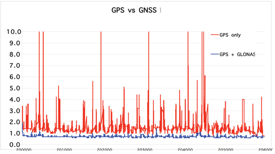
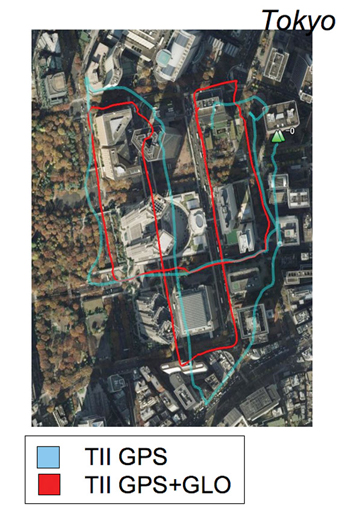
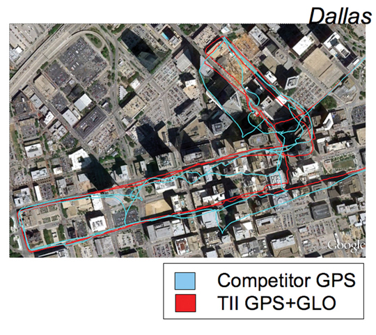
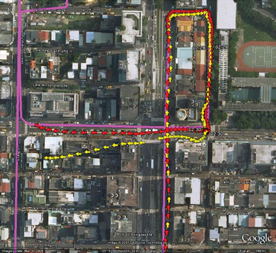
    Static and kinematic tests show that EGNOS performs well in both cases: “The EGNOS SDK provides an average increase of 30 percent in position accuracy over GPS alone,“ according to developer DKE Aerospace.


    EGNOS Software Development Kit provides a software receiver to enhance GPS positions, displaying position accuracy increases on average of 30 percent.


    DOT Blank Stare on LightSquared

    The U.S. Department of Transportation (DoT) responded to a Freedom of Information Act (FOIA) request by GPS World for its recommendations to the National Telecommunications and Information Administration (NTIA) regarding LightSquared interference with GPS. The DoT wrote, “We are withholding two pages [of thirteen relevant pages] in part and eleven pages in their entirety,” and enclosed two completely blacked-out pages.
    Kathy Ray, DoT FOIA officer, added,  “We have determined that the release of the redacted and withheld portions would foreseeably cause harm to the government’s deliberative process.”

    The blacked-out DOT letter is dated August 25, 2011. How it differs from the agency’s July 21 “LightSquared Impact Assessment,” publicly available courtesy of the U.S. House of Representatives Committee on Science, Space, and Technology, cannot, of course, be known.

    The Department of Homeland Security wrote in response to GPS World’s FOIA request, “We conducted a comprehensive search of files with the Science and Technology Directorate’s Homeland Security Enterprise and First Responders Group, and Cyber Security Division for records that would be responsive to your request. Unfortunately, we were unable to locate or identify any responsive records.”

    The National Institute of Standards and Technology of the Department of Commerce replied, “NIST has no documents that are responsive to your request.”

    The Department of the Interior provided the same documents that were previously made public by the House committee.

    The National Aeronautics and Space Administration made a similar determination, but did not send a document, referring instead directly to the committee’s public website.

    PNT Board Hears Proposal for LightSquared Solution

    The  November 9 meeting of the National Space-Based Position Navigation and Timing (PNT) Advisory Board in Alexandria, Virginia got several earfulls regarding the LightSquared/GPS controversy. One of seven speakers on a two-hour panel, Javad Ashjaee, president and CEO of JAVAD GNSS, demonstrated his company’s newly developed filter technology that he said could protect GPS receivers from LightSquared broadband network interference.

    As Ashjaee stated, the proposed solution does not protect against interference from the so-called high-10 signals, one of two bands (the other is known as the low-10) for which LightSquared has received a conditional waiver. Unless and until a solution for the terrestrial high-10 signals is found, LightSquared transmissions in that band will still interfere with the GPS signal. The technical solution proposed by JAVAD GNSS addressed only the low-10 band.


    Proposed filter to “harden” high-precision GPS receivers against Lightsquared Lower 10 (click to enlarge.)
    The JAVAD GNSS proposed fix consists, in simplified form, of a ceramic filter followed by a series of surface acoustic wave (SAW) filters.
    A PDF of Ashjaee’s 76-slide Powerpoint demonstration, without his verbal explanations and commentary, along with other presentations from the board meeting, are available at www.pnt.gov/advisory/2011/11/. A December 8 GPS World webinar reprised the same presentation, and the download at env-gpsworld-integration.kinsta.cloud/webinar includes audio of Ashjaee’s remarks.

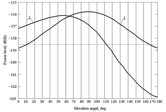
    Ashjaee said that his company’s testing of its own filter methodology found no GPS signal loss due to a low-10 (10L) signal power of –10 dBm. An “Ultimate Test: Special Zero Baseline” put receivers on a Moscow skyscraper with multipath from both above and below. One antenna fed two receivers (zero baseline). One receiver used standard filtering and the other the new filters. He said that over 15 hours of testing the average carrier-phase error between the two receivers was 0.2 millimeters, and the average code difference was about 5 centimeters.

    JAVAD GNSS has started production of what Ashjaee calls “LightSquared-compatible” Triumph GNSS receivers. He brought 40 units to the PNT Board meeting. The company will begin manufacturing “LightSquared-integrated” receivers in May 2012, for RTK positioning using the proposed LightSquared broadband network for high-speed communication, if and when it is deployed.

    Fellow presenter Jim Kirkland, vice president and general counsel for Trimble Navigation, pointed out that such filters represented a potential solution only for one class of high-precision receivers. Whether it would work for other classes of high-precision receivers had yet to be verified. Kirkland said that even if further independent testing shows that the filter solution is viable at the lower 10 MHz of the spectrum, retrofits would be costly and time consuming.

    Questions regarding cost and responsibility of retrofit, should the solution prove practical, were not discussed at length at the meeting, nor was any solution proposed.

    LightSquared executive vice president Martin Harriman did not directly answer a question as to whether his company intends to develop the upper 10 MHz for which it has been given a conditional waiver.

    Scott Burgett, software engineering manager for Garmin International, said, “It is almost impossible to design new products compatible with LightSquared’s proposed system without knowing its technology’s end state.” He estimated 10–15 years to properly retrofit Garmin devices, which are widely distributed in general aviation, personal navigation, car navigation, and other sectors, so that they could coexist with LightSquared.

    The panel was moderated by Tom Stansell of Stansell Consulting, who concluded, “I think we learned, thanks to Javad, about a very clever solution to a particular problem for a particular range of products — the products he is most familiar with. It may or may not fit in some of the other applications.

    “What we have not addressed is the elephant in the living room,” Stansell continued. “That is the cost, and time delay, and changeover process if LightSquared is allowed to go forward. Will it be the lower 10, upper 10? That has to be resolved. There are very large questions remaining to be discussed, and [they] may or may not be fully solved in a short period of time.”

    Constellation Updates

    Where Is Compass ICD?

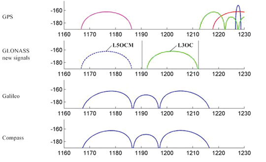
    The long-awaited signal interface control document (ICD) for China’s Beidou/Compass GNSS has not yet appeared, despite an announcement at the ION-GNSS conference by Chinese delegates that ICD document v1.0 will be published in 2011, “probably” in the month of October. When it does appear, it should be available for download on the Compass website, www.beidou.gov.cn (as yet without an English version), also at www.compass.gov.cn.

    The delay in publishing a document may reflect a system very much in formulation, with ongoing discussions among the principal parties to its design, with different views on system architecture and possibly even final signal structure. This was one possible conclusion that could be inferred — a dynamic system in formation and growing rapidly — from varying reports given by different Chinese representatives, governent and academic, at the ION Compass session.

    There was some disagreement among panelists at that time as to, for example, the final targeted number of satellites in the system: either 30, or 35.

    The ICD has been rumored to be available previously to receiver manufacturers within China, creating some disgruntlement among companies outside the country. One of the ION panelists affirmed that GPS/Compass chips and receivers are being actively developed by many Chinese manufacturers and research institutes.

    The next BeiDou/Compass launch, which will be for the system’s fifth inclined geosynchronous orbit satellite, is expected during the first few days of December, according to web discussions. As of press time for this magazine, there had been no official announcement on the Chinese official government BeiDou website, www.compass.gov.cn.

    The site has posted Chinese and English versions of a document titled “Report on the Development of BeiDou (COMPASS) Navigation Satellite System (V1.0)” by the China Satellite Navigation Office. The pages are viewable as separate images.

    Galileo Under Control

    Europe’s first two in-orbit validation satellites reached their final operating slotss 23,222 kilometers above Earth, have been activated, and are now undergoing tests of their navigation payloads, reports the European Space Agency (ESA).

    Marking the formal end of their Launch and Early Operations Phase, control of the satellites passed on November 3 from the French space agency (CNES) center in Toulouse to the Galileo Control Centre in Oberpfaffenhofen, Germany.

    Oberfaffenhofen, operated by the German Aerospace Center (DLR), will be in charge of the satellites’ command and control for the whole of their 12-year operating lives. The navigation signals are being checked out by ESA’s ground station in Redu, Belgium, where a 20-meter antenna measures the shape of the signals to a high degree of accuracy. Once the navigation payload is fully checked out and activated, a second Galileo Control Centre in Fucino, Italy, will oversee all navigation services. All activities are performed under contract to SpaceOpal, a joint subsidiary of DLR and the Italian company Telespazio.
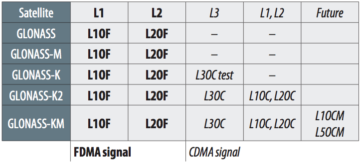
    GLONASS as Expected

    The Satellite System Mission Control Center of the Russian Ministry of Defence, with the ISS-Reshetnev Information Computation Center, established communication with the three GLONASS satellites launched November 4. The satellites are earth- and sun-oriented, and their subsystems are functioning properly.

    According to NORAD tracking, the three satellites were inserted into Plane 1. This was expected as there are only seven active satellites in this plane, whereas the other two planes have a full complement of eight satellites. Orbit slot 3 in Plane 1 is currently vacant. According to Nikolay Testoyedov, ISS-Reshetnev general designer and director general, the new satellites will ensure the operation of a complete 24-satellite GLONASS constellation, and allow creating the necessary orbital reserve.

    GPS GEO-MEO Floated

    In a presentation titled “Analysis of Alternatives  for Future GPS Architecture; Considerations for Constellation Sustainment,” made to the U.S. PNT Advisory Board on November 9, Kirk Lewis, senior advisor from the Institute for Defense Analyses (IDA), put forth the concept of “boosting” GPS III payloads onto commercial geostationary Earth-orbit (GEO) satellites.

    After concluding that the current program of launches and orbit costs extending into the Block III-C generation is not sustainable, Lewis presented several alternatives, but quickly eliminated two that involved low-Earth-orbit satellites and non-space options, due to technical, scheduling, and performance issues. Remaining in play are “potential and realistic” GEO and mid-Earth orbit (MEO, the configuration of the present GPS constellation) options, used individually or in combination.

    IDA analysis found that two GEO satellites, separated by 15 degrees or more longitude, supplied almost the same signal performance as adding six MEO satellites. The presentation is available at www.pnt.gov/advisory/2011/11/.

  • Expert Advice: MSS Misinformation, and Ten Truths

    By Rich Keegan

    LightSquared is currently conducting a public campaign intended to persuade federal regulators to approve a nationwide broadband service that would be detrimental to users and applications that depend on GPS. The campaign relies on misinformation, revisionist history, half-truths, and clear misstatements of fact. To understand the effort to convince regulators and legislators that the experts are wrong, one must consider 10 basic truths.

    1: The MSS Band Was Not Meant for High-Powered Terrestrial Use. The FCC authorized use of ancillary terrestrial component (ATC) ground transmitters many years ago within the mobile satellite services (MSS) band. The LightSquared campaign claims that this proves the band was intended for primary high-powered terrestrial use. But note ATC means ancillary terrestrial component, not primary. The FCC allowed this use only to fill in small holes in coverage from satellites. The term MSS recognizes that the band was for use by low-powered satellites, not high-powered land transmitters.

    The FCC conditional waiver given to LightSquared, if allowed to stand, would completely change the nature of the band, converting it to primary terrestrial use by 40,000 or more high-powered ground transmitters. Many FCC statements preceding the conditional waiver make it clear that the LightSquared effort is precisely what the FCC said would not be permitted.

    2: Interference to GPS Has Not Been Resolved. LightSquared assured the GPS community when the conditional waiver was announced that all interference issues had been addressed, and its system would not interfere with GPS. It was immediately clear to GPS engineers that this was wrong, and subsequent testing ordered by the FCC, along with that done by manufacturers, federal agencies, and independent organizations, confirmed that the original LightSquared system would cause massive interference with all classes of GPS receivers.

    Faced with irrefutable evidence of massive interference, LightSquared revised its system design to propose initial use of only 10 MHz of spectrum farthest from the GPS band (Low 10) for an unspecified period of time, after which it would be allowed to add the closer 10 MHz (High 10). While it may be feasible in the future to develop GPS receivers that could tolerate Low 10, several things are reasonably clear:

    • High-precision receivers that can tolerate High 10 and work as well as the ones we now use can’t be built, now or in the foreseeable future. LightSquared’s claims that “we can innovate our way out of this” are wrong with respect to High 10. Filters that LightSquared presently touts to allow Low 10 would not work in the High 10 environment.
    • Based on limited testing and analysis, Low 10 causes less interference than the original plan of Low 10+High 10, but the Low 10 effects on many receivers, particularly high-precision receivers in many high-value applications, remains substantial.

    With this plan, LightSquared claims that 99 percent of existing GPS receivers would not suffer harmful interference. This conclusion relies on a definition of harmful interference of C/N0 degradation of 6 dB for general navigation devices (the GPS industry and FCC precedent require only 1 dB), and on testing cell-phone GPS with a simple pass/fail criterion, ignoring performance degradation and the fact that modern cell phones are much more like general navigation devices and PNDs than older cell phones. Slanted and unorthodox analytical parameters produced this rosy assessment.

    Based on evidence of Low-10 interference, the NTIA and FCC ordered more testing specifically focused on Low 10. In response to mounting evidence of interference at this level also, LightSquared has now offered a third version of its system architecture, using Low 10 and limiting power on the ground. From a GPS interference perspective, this power reduction is useful. However, the latest LightSquared plan does not fully address three key problems:

    • There has been no renunciation of High 10. LightSquared says that in 5–6 years it will need spectrum capacity beyond Low 10. It would be irrational to design receivers now that tolerated Low 10, only to find in a few years that the requirements had changed to require tolerance to High 10 also (which is not possible).
    • There will still be interference with GPS receivers of various important classes in the power-limited environment of the latest plan.
    • None of the evolving plans deals with the massive installed base of GPS receivers.

    3: The GPS Industry Did Not Know of a Spectrum Conversion. LightSquared claims that for many years GPS manufacturers were aware of the proposed ground transmitters and should have designed receivers to avoid picking up strong signals in this neighboring band. These claims of foreknowledge of a recent fundamental change in proposed use of the MSS band are fallacious.

    The U.S. GPS Industry Council at the time of the limited conditional approval of ATC transmitters (circa 2003) consisted of only two or three GPS manufacturers. It is clear from USGIC statements at the time that it did not anticipate a spectrum reallocation. In any case, it is a huge stretch to claim that USGIC represented all GPS manufacturers, let alone the entire GPS industry and users. The GPS industry had no indication that the FCC would ever radically reallocate MSS band for a stand-alone high-powered terrestrial network, prior to November 2010.

    As [GPS World survey editor] Eric Gakstatter has pointed out, a major change with the potential to affect all GPS users should follow certain guidelines. The Air Force GPS Directorate demonstrated this in handling a much less important change to GPS signals: discontinuing support for the semi-codeless technique used in most high-performance receivers. In 2008, it hired consultants to question all manufacturers and many users of GPS about the potential impact. It then proposed that the signal change would occur on December 31, 2020, giving more than 12 years to prepare for the change.

    Should we ask anything less from LightSquared’s far more radical proposal?

    The FCC has a process that would have been much more appropriate for a proposal to reallocate the MSS L-band to high-powered terrestrial use: Notice of Proposed Rulemaking. Had it followed this process, we might be having a productive discussion of technical aspects.

    4: GPS Receivers Properly Use the MSS L-Band. LightSquared asserts that GPS receivers intrude into LightSquared’s spectrum— a misleading claim. Many GPS receivers in fact have filters that do not block signals from the MSS band. There are several reasons for this:

    • So long as the MSS band was a satellite band for signals from space to Earth, the signals from other systems in that band were low-power and not harmful to GPS reception. GPS receiver designers relied on this and assumed this allocation of the band would continue. The ability to use filters that overlap into the MSS band has enabled both low-cost and high-precision GPS receivers.
    • High-precision receivers cannot produce accurate measurements without using wideband GPS signals that occupy most or all of the GPS band. “Brick wall” filters that could capture all the energy in the GPS band and none of the energy in the adjacent MSS band do not exist.
    • Lightsquared ignores hundreds of thousands of high-accuracy, high-value GPS receivers that receive signals from the MSS band, using it for its intended purpose — satellite to ground communication. Deere receivers use the StarFire system leasing use of transmitters on MSS band Inmarsat satellites. Trimble leases use of MSS band on LightSquared’s own satellites for OmniSTAR correction signals.
    • GNSSs worldwide are modernizing their signals; many of these new signals are wideband. To take advantage of them, modern receivers of all classes will be wideband, as high-precision receivers are now, and will suffer interference similar to that of high-precision receivers now.

    5: GPS Receivers Do Not Ignore Government Design Standards. LightSquared asserts that the fundamental GPS L1 signal specification mandates receiver design standards that the GPS industry has ignored, to save a few cents of cost. These claims are false. The GPS specification defines the signal-in-space and explicitly says that it is not a receiver design standard; it simply uses a nominal receiver design to be able to translate signal-in-space specification into navigation performance effects.

    6: Receiver Replacement Costs and Schedules Are Large. LightSquared has offered $50 million to fund retrofit or replacement of legacy government receivers impacted by its signals. General Shelton of the Air Force Space Command testified to Congress that it would take billions of dollars to replace or retrofit the government receivers. He also estimated a 10-year time frame to test and validate replacement receivers.

    LightSquared says it will not bear the costs of replacing commercial receivers since, it claims, manufacturers are responsible for the improper design of those receivers. This is wrong, as shown earlier. LightSquared should bear the cost of replacing commercial receivers, if allowed to proceed. A realistic time frame needed to replace high-accuracy, high-value commercial receivers is also about 10 years.

    LightSquared argues that in five years, most current GPS receivers will be obsolete. This is clearly not true. Many current high-precision receivers are already prepared to use modernized signals from GNSS constellations. The L1C GPS civil signal, for instance, will not be available on any satellite until 2014, and the full constellation of satellites with L1C will not be available until 2026. Therefore, many receivers in use now will continue to be in use for many more years than five.

    7: Other GNSS Are Also Affected. Because Galileo, Compass, and GLONASS use or will use signals similar to GPS, in the same band as GPS, they will suffer interference very similar to that suffered by GPS. Users will lose the benefits of these other constellations, as well as GPS.
    The United States has entered into formal obligations to protect some other GNSS signals; LightSquared signals are not compatible with these U.S. obligations.

    8: Handset Interference is a Serious Concern. LightSquared handsets do not yet exist, but testing to date makes it clear that the handset signals to communicate with LightSquared base stations also interfere with GPS receivers when they are nearby (a few meters). The interference to GLONASS reception is also likely to be harmful. The interference effects of a group of LightSquared handsets has not been fully evaluated, but will certainly create more interference for nearby receivers.

    Out-of-band emissions from LightSquared handsets, if as high as FCC power masks currently permit, would substantially interfere with all GPS receivers, possibly more than LightSquared base stations.

    9: The Solution Is Not a $6 Filter. LightSquared displayed a Deere high-precision receiver with a “$6 filter” and told Congress this proved it could be done inexpensively and quickly. The claim is based on half-truths.

    • The Low 10 signal can be filtered out using low-cost parts, but the effect on performance is not known. There is good technical reason to be concerned about degraded performance from this filtering.
    • The Deere receiver displayed is not capable of readily being retrofitted with LightSquared’s or any other filter. Like many high-precision units, it is an integrated, hermetically sealed device. Retrofitting would entail returning the unit to the factory, cutting open and discarding the case, replacing the antenna/preamp assembly with a redesigned antenna/preamp assembly, inserting the unit into a new case and sealing it, re-testing the unit, and returning it to the customer. A costly process.
    • Filtering is one element of a design, usually distributed across several stages of the receiver. Changing filtering requires a redesign that may stretch across the entire RF front end, and cannot be done casually.
    • The displayed filter’s specified insertion loss is 3 dB, well above what GPS designers normally accept, and would result in about 2 dB more loss of sensitivity than with current filters.
    • LightSquared has suggested moving StarFire and OmniSTAR augmentation signals to the top of the MSS band, very close to the GPS band, so that filters that included GPS could include them. This is a reasonable approach, but the “$6 filter” might not permit that, as it would excessively attenuate at least the StarFire signal.

    10: The GPS Industry Supports National Broadband. The GPS industry broadly supports the goal of extensive and pervasive national broadband, and of strong competition among providers. Pervasive broadband would be helpful for applications such as real-time kinematic (RTK) positioning. It would be beneficial to GNSS users to have broadband services available everywhere, but not if the cost is to degrade or deny GNSS service.

    LightSquared’s broadband services require terrestrial base stations and cannot be done with the LightSquared satellites. It is unlikely that low-population areas will be covered with terrestrial base stations due to the economics involved, but if broadband coverage is nationwide, then so too will be GPS interference.


    Rich Keegan is a senior principal engineer at NavCom Technology, Inc., a wholly owned subsidiary of Deere and Company.

  • Consumer GPS/GLONASS: Accuracy and Availability Trials of a One-Chip Receiver in Obstructed Environments

    By Philip Mattos, STMicroelectronics R&D Ltd.

    A one-chip multiconstellation GNSS receiver, now in volume production, has been tested in severe urban environments to demonstrate the benefits of multiconstellation operation in a consumer receiver. Bringing combined GPS/GLONASS from a few tens of thousands of surveying receivers to many millions of consumer units, starting with satnav personal navigation devices in 2011, followed by OEM car systems and mobile phones, significant shifts the marketplace. The confidence of millions of units in use and on offer should encourage manufacturers of frequency-specific components, such as antennas and SAW filters, to enter volume mode in terms of size and price.

    One-chip GPS/GLONASS receiver trials in London, Tokyo, and Texas sought to demonstrate that the inclusion of all visible GLONASS satellites in the position solution, in addition to those from GPS, produces much greater availability in urban canyons, and in areas of marginal availability, much greater accuracy.

    Multi-constellation receivers are needed at the consumer level to make more satellites available in urban canyon environments, where only a partial view of the sky is available and where extreme integrity is required to reject unusable signals, while continuing to operate on other signals deeply degraded by multiple reflection and attenuation. This article briefly outlines the difficulties of integrating a currently non-compatible system (GLONASS), offering an economic solution in the mass market where cost is king, but performance demands in terms of low signal, power consumption, time-to-first-fix, and availability are extreme. While the accuracy achieved is not at survey levels, we deem it sufficient to meet consumer demands even at the worst signal conditions.

    The aim is to provide improved indoor and urban canyon availability for mass-market GNSS by using all available satellites; in 2011, that requires GLONASS support, as the constellation availability precedes Galileo by around three years. The aim is to overcome the hardware incompatibility issues of GLONASS, that is, its frequency division multiple access (FDMA) signal rather than the code division multiple access format used by GPS, different centre frequency, and different chipping rate, all without adding significantly to the silicon cost of the receiver chipset. This then allows a total satellite constellation of about 50 to be used at present, even before two recently launched Galileo IOV satellites.

    It is expected that in benign conditions the additional satellites will give little benefit, as availability approaches 100 percent, and accuracy is excellent, with GPS alone. Though dominated by the ionosphere, using seven, eight, or nine satellites in the fix minimises the amount of error that feeds through to the final position.

    In marginal conditions, where GPS can give a position, but is using 3/4/5 satellites and those are clustered in the narrow visible part of the sky resulting in poor DOP values, the increased number of satellites benefits the accuracy greatly, due to both improved DOP and multipath-error averaging. Limited satellites mean the full multipath errors map into position and are magnified by the DOP. Adding the second constellation means more clear-view satellites for accuracy, more total satellites to minimise the errors, and the errors are less magnified by the geometry due to better DOP.

    In extreme conditions, where insufficient GPS satellites are seen to give a fix, the additional GLONASS satellites increase the availability to 100 percent (excluding actual tunnels).

    Availability is a self-enhancing positive feedback loop… if satellites are always tracked, even if rejected on a quality basis by the RAIM/fault detection and exclusion (FDE) algorithms, then they do not need to be reacquired, so become available for use earlier. If position can be maintained, then the code phases for obstructed satellites can continue to be predicted accurately, allowing instant reacquisition after obstruction, and instant use as no code pull-in time is required. Once availability is lost, the reverse applies, as wrong position means worse prediction, longer re-acquisition, and hence again less availability.

    The extra visible satellites are very significant for the consumer, particularly — as for example with self-assistance where the minimum constellation is five satellites, not three to four — to autonomously establish that all satellites are healthy using receiver-autonomous integrity monitoring (RAIM) methods. Self-assistance has further major benefits for GLONASS, in that no infrastructure is required, so there will be no delay waiting for GLONASS assistance servers to roll out. The GLONASS method of transmitting satellite orbits is also very suitable for the self-assistance algorithm, saving translation into and out of the Kepler format.

    Significance of Work

    Previous attempts to characterize the multi-constellation benefits in urban environments have been handicapped by the need to use professional receivers not designed for such signal conditions, and by the need to generate a separate result for each constellation or sacrifice one satellite measurement for clock control. These problems made them unrepresentative of the performance to be expected from the volume consumer device.

    This new implementation is significant in being a true consumer receiver for high sensitivity, fully integrated both for measurement and for computation. Thus fully realistic trials are reported for the first time.

    Background

    The tests were performed on the Teseo-II single chip GNSS receiver (STA-8088). A brief history: our 2009 product Cartesio+ already included GPS/Galileo, and the digital signal processor (DSP) design has been extended to include GLONASS also for Teseo2, the 2010 product. Test results with real signal data through FPGA implementations of the baseband started in late 2009, and with the full product chip in 2010.

    The architectural design showed that the silicon could be implemented with only small additional silicon area. Changes to the baseband DSP hardware and software were small and were included in the next scheduled upgrade of the chip, Teseo2. The RF chip silicon requires much greater attention, duplicating the intermediate frequency (IF) path and analog-digtal converter (ADC), with additional frequency conversion and a much wider IF filter bandwidth; however, as the RF silicon area is very small in total, even a 30 percent increase here is not a significant percentage increase on the whole chip. As the design is for an integrated single chip system (RF and baseband, from antenna to position, velocity, and timing (PVT) solution), the overall silicon area on a 65-nanometer process is very small.

    Commercially, it is new to include all three constellations in a single consumer chip. Technically it is new to use a pool of constellation-independent channels for GLONASS, though standard for GPS/Galileo. Achieving this flexibility has also required new techniques to manage differing RF hardware delays, different chipping rates, in addition to the coordinated universal time (UTC) offset and geoid offset problems already well known to the surveying community.

    It is also very unusual to go direct to a single-chip solution (RF+baseband+CPU) for such a major technology step. The confidence for this step comes from the provenance of the RF and the baseband, the RF being an extension of the STA5630 RF used with Cartesio+, and the baseband being significant but not major modifications of the GPS/Galileo DSP used inside Cartesio+. 5630/Cartesio+ were proven in volume production as separate chips before the single-chip three-constellation chip starts production.

    The steps forward from the previous generation of hardware are on chip RF, Galileo support, GLONASS support. While Galileo can pass down the existing GPS chain, with appropriate bandwidth changes, additional changes are required for GLONASS: see Figures 1 and 2.

    figure1 Philip Mattos, STMicroelectronics R&D Ltd.
    Figure 1. RF changes to support GLONASS.
    figure2 Source: Philip Mattos, STMicroelectronics R&D Ltd.
    Figure 2. Baseband changes to support GLONASS.


    In the RF section, the LNA, RF amp, and first mixer are shared by both paths, in order to save external costs and pins for the equipment manufacturer, and also to minimize power consumption. Then the GLONASS signal, now at around 30 MHz, is tapped off into a secondary path shown in brown, mixed down to 8 MHz and fed to a separate ADC and thus to the baseband.

    In the baseband, an additional pre-conditioning path is provided, again shown in brown, which converts the 8 MHz signal down to baseband, provides anti-jammer notch filters, and reduces the sample rate to the standard 16fo expected by the DSP hardware.

    The existing acquisition engines and tracking channels can then select whether to take the GPS/Galileo signal, or the GLONASS signal, making the allocation of channels to constellations completely flexible.

    Less visible but very important to the system performance is the software controlling these hardware resources, first to close tracking loops and take measurements, and secondly the Kalman filter that converts the measurements to the PVT data required by the user. This was all structurally modified to support multiple constellations, rather than simply adding GLONASS, in order that future extensions of the software to other future systems becomes an evolutionary task rather than a major re-write.

    The software ran on real silicon in 2010, but using signals from either simulator or static roof antennas, where accuracy and availability of GPS alone are so good that there is little room for improvement. In early 2011, prototype satnav hardware using production chips, antennas, and cases became available, making mobile field trials viable.

    Actual Results

    Results have already been seen from trials using professional receivers with independent GPS and GLONASS measurements. However, those tests were not representative of the consumer receiver because they are not high sensitivity; because the receivers require enough clean signal to operate a PLL, which is not realistic in a mobile city environment; and because they were creating two separate solutions, thus needing a continuous extra satellite to resolve inter-system time differences.

    A 2010 simulation of visible satellites in a typical urban canyon of downtown Milan, Italy, produced the results, every minute averaged for a full 24 hours, shown in Table 1. The average number of satellites visible rises from 4.4 with GPS alone, to 7.8 for GPS+GLONASS, with the result that there are then zero no-fix samples. With GPS alone there were 380 no-fix samples, or 26 percent of the time.

     Table 1. Accuracy and availability of GPS and GPS+GLONASS, averaged over 24 hours. Source: Philip Mattos, STMicroelectronics R&D Ltd.
    Table 1. Accuracy and availability of GPS and GPS+GLONASS, averaged over 24 hours.

    However, availability is not itself sufficient. Having more satellites in the same small piece of sky above the urban canyon may not be sufficient, due to geometric accuracy limitations. To study this, the geometric accuracy represented by the HDOP was also collected, and shows an accuracy 2.5 times better.

    Previous studies suggested that in the particular cities tested, two to three additional satellites were available, but one of these was wasted on the clock solution. Using the high-sensitivity receiver, we expected four or five extra satellites and none wasted.

    The actual results far exceeded our expectations. Firstly, many more satellites were seen, as all previous tests and simulations had excluded reflected signals. Having many more signals, the DOP was vastly improved, and the effect of the reflections on accuracy was greatly reduced, both geometrically, and by the ability of the FDE/RAIM algorithms to maintain their stability and down-weight grossly erroneous signals rather than allow them to distort the position.

    The results presented here are from a fully integrated high-sensitivity receiver optimized to use signals down to very low levels, and to give a solution derived directly from all satellites in view, no matter which constellation.

    This produces 100 percent availability, and much improved accuracy in the harsh city environment.

    Availability

    The use of high-sensitivity receivers, not dependent on phase-locked loops (PLLs) for tracking, produces 100 percent availability in modern cities, even high-rise, due to the reflective nature of modern glass in buildings, even for GPS alone. Thus some other definition of availability is required rather than “four sats available,” such as sats tracked to a certain quality level, resulting in a manageable DOP. Even DOP is difficult to assess, as the Kalman filter gives different weights to each satellite, not considered in the DOP calculation, and also uses historic position and current velocity, in addition to instantaneous measurements, to maintain the accuracy of the fix.

    Figure 3 shows the availability of tracked satellites in tests in the London City financial district in May 2011.

    figure3 Source: Philip Mattos, STMicroelectronics R&D Ltd.

    As can be seen, there are generally seven to eight GLONASS satellites and eight to nine GPS satellites, for a total of around 16 satellites. The only period of non-availability was in a true tunnel (Blackfriars Underpass) at around time 156400 seconds. In other urban canyons, around time 158500 and 161300, individual constellations came down to four satellites, but the total never fell below eight. Note this is an old city, mainly stone, so reflections are limited compared with glass/metal buildings.

    While outside tunnels, availability is 100 percent, this may be limited by DOP or accuracy. As can be seen in Figure 4 on another London test, the GNSS DOP remains below 1, as might be expected with 10–16 satellites, while GPS-only frequently exceeds four, with the effect that any distortions due to reflections and weak signals are greatly magnified, with several excursions over 10.

     Figure 4. GPS-only versus combined GPS/GLONASS dilution of precision. Source: Philip Mattos, STMicroelectronics R&D Ltd.
    Figure 4. GPS-only versus combined GPS/GLONASS dilution of precision.

    As the May 2011 tests had not been difficult enough to stress the GPS into requiring GNSS support, a further trial was performed in August 2011. This was in a modern high-rise section of the city, Canary Wharf, shown in Figure 5 on an aerial photograph. In addition to being high-rise, the roads are also very narrow, resulting in very difficult urban canyons. Being a modern section of the city, the buildings are generally reflective glass and metal, rather than stone, testing RAIM and FDE algorithms to the extreme.

     Figure 5. GPS versus GNSS, London Canary Wharf (click to enlarge.) Source: Philip Mattos, STMicroelectronics R&D Ltd.
    Figure 5. GPS versus GNSS, London Canary Wharf (click to enlarge.)

    This resulted in difficulty for the GPS-only solution, shown in green, especially in the covered section of the Docklands station, center-left, lower track.

    Figure 6 shows the same test data displayed on truth data taken from the ordnance survey vector map data of the roads.

     Figure 6. GPS versus GNSS, London Canary Wharf, on vector truth (click to enlarge.) Source: Philip Mattos, STMicroelectronics R&D Ltd.
    Figure 6. GPS versus GNSS, London Canary Wharf, on vector truth (click to enlarge.)

    The blue GNSS data is then extremely good, especially on the northern (eastbound) part of the loop (UK drives on the left, thus one-way loops are clockwise).

    Further tests were carried out by ST offices around the world. Figure 7 shows a test in Tokyo, where yellow is the previous generation of chip with no GLONASS, red was Teseo-II with GPS plus GLONASS.

     Figure 7. Teseo-I (GPS) versus Teseo-II (GNSS) in Tokyo test. Source: Philip Mattos, STMicroelectronics R&D Ltd.
    Figure 7. Teseo-I (GPS) versus Teseo-II (GNSS) in Tokyo test.

    Again, here the scenario is not sufficiently challenging to hurt the availability even of GPS alone, but the accuracy is limited.

    Figure 8 gives some explanation of the accuracy problems, by showing the DOP during the test. It can be seen that Teseo-II DOP was rarely above 2, but the GPS-only version was between 6 and 12 in the difficult northern part of the test, circled for illustration.

     Figure 8. DOP during Tokyo tests (click to enlarge.) Source: Philip Mattos, STMicroelectronics R&D Ltd.
    Figure 8. DOP during Tokyo tests (click to enlarge.)

    Further Tokyo tests were performed entering the narrower urban canyons in the same test area, shown in Figure 9. Blue is GPS only, red is GPS+GLONASS, and the major improvement is obvious.

    Figure 9. GPS only (blue) versus GNSS (red), Tokyo. Source: Philip Mattos, STMicroelectronics R&D Ltd.
    Figure 9. GPS only (blue) versus GNSS (red), Tokyo.

    Figure 10 uses the same color scheme to illustrate tests in Dallas, this time with a competitor’s GPS receiver versus Teseo-II configured for GPS+GLONASS, again a huge benefit.

     Figure 10. GPS only (blue, competitor) versus GNSS (red), Dallas.
    Figure 10. GPS only (blue, competitor) versus GNSS (red), Dallas.

    Other Constellations

    While Teseo-II hardware supports Galileo, there are no production Galileo satellites available yet (September 2011), so the units in the field do not have Galileo software loaded.

    However, the Japanese QZSS system has one satellite available, transmitting legacy GPS-compatible signals, SBAS signals, and L1C BOC signals. Teseo-II can process the first two of these, and while SBAS is no benefit in the urban canyon as the problems of reflection and obstruction are local and unmonitored, the purpose of QZSS is to provide a very high-angle satellite, so that it is always available in urban canyons.

    Figure 11 shows a test in Taipei (Taiwan) using GPS (yellow) versus GPS plus one QZSS satellite in red, with the truth data shown in purple.

    figure11_B Source: Philip Mattos, STMicroelectronics R&D Ltd.
    Figure 11. GPS only (yellow) versus GPS+QZSS(1 sat, red), truth in purple, Taipei (click to enlarge.)

    Further Work

    The test environment will be extended to yield quantitative accuracy results for UK tests where we have the vector truth data for the roads.
    The hardware flexibility will be extended to support Compass and GPS-III (L1-C) signals, in addition to Galileo already supported. Acquisition and tracking of these signals have already been demonstrated using pre-captured off-air samples.

    In 2010, the Compass spec was not available. Thus the Teseo-II silicon design was oriented to maximum flexibility in terms of different code lengths, such as BOC or BPSK, so that by using software to configure the hardware DSP functions, the greatest chance of compatibility could be achieved.

    The result was only a marginal success, in that the 1561 MHz frequency of the regional Compass system can only be supported using the flexibility of the voltage-controlled oscillator and PLL, meaning that it cannot be supported at the same time as other constellations. Additionally, the code rate on the regional system is also 2 M chips/second, which is not supported, so is approximated by using alternate chips, producing serious signal loss.

    So the hooks for Compass are only useful for research and software development, either for a single-constellation system, or using a separate RF front end.

    The worldwide Compass signal, which is on a GPS/Galileo signal format in both carrier frequency and in code length and rate, will be directly compatible, but is not expected to be fully available until 2020.

    The city environment testing will be repeated as the Galileo constellation becomes available. With 32 channels, an 11/11/10 split (GPS/Galileo/GLONASS) may be used when all three constellations are full, but for the next few years 14/8/10 satisfies the all-in-view requirements.

    Conclusions

    The multi-constellation receiver can include GLONASS FDMA at minimal increased cost, and with its 32 channels tracking up to 22 satellites in a benign environment, even in the harshest city environment sufficient satellites are seen for 100 percent availability and acceptable accuracy. 10–16 satellites were generally seen in the urban canyon tests. The multiplicity of measurements allows RAIM and FDE algorithms to be far more effective in eliminating badly reflected signals, and also minimizes the geometric effects of remaining distortion on the signals retained.

    Acknowledgments

    ST GPS products, chipsets, and software, baseband and RF are developed by a distributed team in Bristol, UK (system R&D, software R&D); Milan, Italy (silicon implementation, algorithm modelling and verification); Naples, Italy (software implementation and validation); Catania, Sicily, Italy (Galileo software, RF design and production); and Noida, India (verification and FPGA). The contribution of all these teams to both product ranges is gratefully acknowledged.


    Philip Mattos received a master’s degree in electronic engineering from Cambridge University, UK, a master’s in telecoms and computer science from Essex University, and an external Ph.D. for his GPS work from Bristol University. He was appointed a visiting professor at the University of Westminster. Since 1989 he has worked exclusively on GPS implementations and associated RF front ends, currently focusing on system-level integrations of GPS, on the Galileo system, and leading the STMicroelectronics team on L1C and Compass implementation, and the creation of generic hardware to handle future unknown systems.

  • The Business and Product Showcase — December 2011

    Download the PDF of The Business and Product Showcase sections from the December 2011 issues here.

  • The Hits and the Misses

    GNSS Design & Test Newsletter, November 2011

    LONDON — Technical conferences usually feature hits: advances in technology, new form factors, improved signal processing. But the opening day of the European Navigation Conference in London has dwelt instead on misses: vulnerabilities, threats, weaknesses that leave GNSS increasingly open to attack and disruption. Gaps in our armor, with scant help in sight.

    The first gloomy note sounded during the opening plenary, usually replete with optimistic constellation updates. Colin Beatty, president of the hosting Royal Institute of Navigation (RIN), noted the first signs of increasing sunspot activity, heralding the oncoming solar maximum, that have caused instances of several minutes of GPS outage at a time around Singapore. Eleven years ago, he remembered, the last solar maximum created outages of four hours daily over an extended period in a Brazilian off-shore drilling area. The current cycle has only just begun.

    This and other types of interference were repeatedly mentioned — LightSquared among them, though not discussed at length — by both speakers and the audience, in questions and comments. Andy Norris, RIN vice-president and conference chair, asked “Why do the governments of this world not seem to be taking seriously the fact of GNSS vulnerability?”

    A representative of the Ireland Lighthouse Authority stated that “The implications of denial of service become more serious with each passing year,” in the sphere of marine navigation, although clearly the remark applies in a much broader, in fact universal context. “Ships are larger, more valuable, they move faster, with smaller crews, and are increasingly reliant on a sole source of positioning and navigation — GPS.”

    When GPS aboard ships was first introduced for navigation, Rein van Gooswilligen of the European Union Group of Institutes of Navigation recalled, it met with some resistance. If you showed a captain a laptop with GPS navigation, they might look at it for five or 10 minutes at a time. Now they are looking exclusively at it, without any supplemental means of navigation, including visual sighting — and other onboard systems have been discontinued.

    An U.S. Navy officer stated that the service is taking a hard, critical look at reliance on GPS, and emphasized the critical timing aspect as well as navigation. The Navy is reconsidering optical navigation including automated optical — and is very interested in a modernized Loran, although the old Loran-C ahs been done away with in the United States.

    “What are we doing wrong or failing to do,” posed Andy Norris again, “ to get our message on vulnerability across to politicians and other key decision-makers?”

    During a coffee break, I got an advance look at possible counter to vulnerability, an integrated eLoran and GPS receiver, smaller than a deck of cards, from Roke Manor Research Ltd. This has great potential for many GNSS-challenged and/or –disrupted environments, and a product should be released soon. That was the one hit of the day.

    Presentations resumed with the largest conference room packed to overflowing for the first of several sessions on interference and jamming. “Spectrum Wars — Give Us This Day Our Daily Bread” was David Last’s chosen title, a paper co-written with Sally Basker, who provided the economic analysis, and one I hope to present in the January issue of GPS World magazine. He calculated the impact on a low-technology product such as bread of the unavailability of high-tech GPS for precision agriculture, transport, and telecoms at every stage of the value chain to show just how pervasive and real a threat to global security it would be if such systems fail or are made to fail. “A dependence on GPS connects many disparate sectors.”

    Last presented the “triple whammy” of denial:

    • Each new satellite in the GPS frequency band also increases the noise level.
    • GNSS nations compete for spectrum.
    • Communication systems compete with GNSS for spectrum.

    And this is not even getting to unintentional RF interference, intentional jamming, and spoofing, he pointed out.

    Intensely political spectrum wars increase GNSS vulnerability, he concluded, and ominously reminded us that the trigger of the French Revolution was . . . an increase in the price of a loaf of bread.

    Durk Van Willigen of Reelektronika began the next talk by stating, “My presentation won’t make you very happy.” He allowed as how the LightSquared battle was fascinating to observe — especially by non-U.S. countries — and should have been expected. There will be more of them, he said.

    “Once upon a time, spectrum was like oil and gas: we had more than we needed.” No more. There’s “No Escape!” he warned, and he pointed out that, on a business basis, GPS and other GNSS spectrum use is free (paid through taxes), while telecommunications companies must pay for spectrum licenses. “As more spectrum will be needed for communication, the pressure on GNSS spectrum is enormous and will increase. Reducing this financial imbalance,” he proposed, “makes GNSS politically more convincing in its spectrum claims.”

    “All the conditions for a gold rush are present,” he concluded, alluding to the frantic grabs that characterize such phenomena. “GNSS — pay for it, or shrink your spectrum need. Be aware and prepare for the next attack.”

    Carl Milner of Imperial College London and Andy Proctor of Chronos Technology then took up the pragmatic, doing side, and even generated a few near-hits, with talks on the GAARDIAN and SENTINEL projects, respectively. GAARDIAN has largely concluded its three-year run to deliver prototype sensors and probes to detect interference and give alarms, as well as detailed analyses of the GNSS environment.  Milner reminded us that 800 billion (British pounds or euros, nearly equivalent at this point), or 6 to 7 percent of Western Europe’s annual gross domestic product, is dependent on GPS. That means 94 billion pounds in the UK, rising yearly.

    The British economy (and by implication the European, U.S., and global economies) is vulnerable, by this dependence, to interruption of the energy supply, breakdown of communications, transport, and financial services, and potential loss of life  — all with no operational monitoring, detection, recourse, or back-up, prior to GAARDIAN and SENTINEL.

    The follow-on SENTINEL is mid-way through its two-year life to take the next requisite steps:

    • Actually locating the interference;
    • categorizing it;
    • determining its extent;
    • giving a determination of trust in GNSS,
    • and addressing spoofing.

    The project has a large user base in law enforcement and government.

    The gloom kept descending like London fog with an after-lunch roundtable discussion on “Threats and Vulnerabilities of GNSS Signals,” moderated by Vidal Ashkenazi of Nottingham Scientific Ltd. A few direct quotes from the speakers, even without specific context provided, should give the flavor of the discussion.

    Tim Just, UK Technology Strategy Board. “Consider the motivation of jamming first: is it in relation to privacy or personal choice, or to criminality? There is perhaps a third case, the hacker community, with intent to disrupt. It is very difficult to quantify those today.  Projects like GAARDIAN and SENTINEL, neither with full national coverage, are only just now starting.

    “There is a choice: remove the jammers, or use other technologies to counter the jamming.  The latter is very expensive, and not available to civil market at the moment.”

    Captain Frank Parker, U.S. Coast Guard. “The recent change to U.S. policy, enabling government agencies to use foreign GNSS services is a very important first step [in combatting jamming and interference].

    “A key factor in determining whether the loss of PNT is due to an external factor, or if it could be something inherent in the receiver, is that the multiple international service providers of GNSS share information about the status and health of their constellations.

    Professor Ashkenazi’s second main question, “What is the additional likely contribution of the Public Regulated Service (PRS) of Galileo?” elicited these responses, much encapsulated here.

    Stefan Baumann, IABG GmbH. “We will get improved signal availability with multi-GNSS, but not such improvement in robustness.  M-code and PRS can help; But M-code restricted to military, so PRS is the way for civil user.”

    Captain Parker. “Market forces drove elimination of other redundant technologies in the past. Market forces will determine the success, or not, of PRS, with its new market cost. In the United States, as the standard positioning service of GPS improved over the years, some users of high-precision services dropped off [and relied just on SPS].  The determining factor is not only cost, but also ease of use.

    Michel Bosco, European Commission. “We are convinced about the added value, especially because of its robustness, of PRS.  We are engaged in discussions with user communities on this. We are planning on users being able to adopt the technology as soon as it is there.”

    Stefan Baumann.  “The courts in Germany have interest in GNSS data which is 100 percent proof against spoofing.”  (Thus PRS.)

    One emerged from the conference — and yes, it is indeed raining in London now — feeling as if one were wearing, not so much a badly chinked suit of armor, but a set of the emperor’s new clothes.

  • Galileo IOV Satellites Reach Operating Orbits

    News from CANSPACE Listserv.

    An announcement from ESA on November 4 stated "Europe’s first two Galileo IOV satellites have reached their final operating orbits, opening the way for activating and testing their navigation payloads." But, based on NORAD/JSpOC tracking of the satellites, it seems that the final orbits were achieved only a day or so ago.

    The plot above (and linked here) shows the mean motion (mm) of the PFM and FM2 satellites since launch. As evidenced by the lengthy gaps in the mm history, it is clear that NORAD/JSpOC sometimes has difficulty in reacquiring satellites after delta-V manoeuvres. We do know, however, that both satellites have appeared to reach their final orbits sometime between November 19 and 23. The mm values are now very close to the value 1.7046556 orbits per day derived from the mean semimajor axis of the Galileo constellation as given in the Galileo Open Service Signal-In-Space Interface Control Document: 29601.297 km.

    The arguments of latitude of the two satellites, essentially in the same orbit plane, are now 40 degrees apart as intended. There have not been any public reports that navigation signals from the satellites have yet been switched on.

  • Galileo Satellites Handed over to Control Center in Germany

    Europe’s first two Galileo satellites have reached their final operating orbits, opening the way for activating and testing their navigation payloads, reports the European Space Agency (ESA).
     
    Marking the formal end of their LEOP Launch and Early Operations Phase, control of the satellites was passed on November 3 from the CNES French space agency center in Toulouse to the Galileo Control Centre in Oberpfaffenhofen in Germany.

    Oberfaffenhofen, operated by the German Aerospace Center DLR, will be in charge of the satellites' command and control for the whole of their 12-year operating lives, ESA said.

    The two Galileo satellites were launched by Soyuz from French Guiana on 21 October. Three hours and 49 minutes after launch, their Fregat-MT upper stage carried them into their planned 23 222 km orbit, where they were released simultaneously.

  • GLONASS Modernization

    By Yuri Urlichich, Valery Subbotin, Grigory Stupak, Vyacheslav Dvorkin, Alexander Povalyaev, Sergey Karutin, and Rudolf Bakitko, Russian Space Systems

    The GLONASS-K satellite, transmitting a CDMA signal in the L3 band, inaugurates a new era of radionavigation signals for both the Russian system and for international GNSS interoperability. As demand for high-precision services through dual- or triple-frequency user equipment increases, GLONASS will come to the forefront. The 2014 GLONASS-K2 satellite will have an FDMA signal in the L1 and L2 bands and CDMA signals in L1, L2, and L3. The overall constellation update will be completed in 2021. Another 2014 launch will fill the Russian SBAS orbit constellation with three geostationary space vehicles.
    Glonass-M-W
    GLONASS-M satellite. (Photos courtesy of Roscosmos and Information Satellite Systems Reshetnev Company)
    Glonass-K-W
    GLONASS-K satellite. (Photos courtesy of Roscosmos and Information Satellite Systems Reshetnev Company).

    With the February launch of the first GLONASS-K satellite, and its transmission of a new CDMA signal in the L3 band, a new era of radionavigation signals has begun: international GNSS interoperability. As we have seen rapidly growing demand for high-precision services provided with dual- or triple-frequency user equipment, introduction of new GLONASS signals in the L1 and L2 bands will come next. The first launch of GLONASS-K2 satellite, with FDMA signals in L1 and L2 bands and CDMA signals in L1, L2, and L3, is planned in 2014. A complete update of the full orbiting constellation will conclude in 2021.

    One satellite per year of the Luch family will be launched into orbit over the next three years, and by 2014 the System of Differential Correction and Monitoring (SDCM) constellation will be in operation with three geostationary space vehicles.

    Constellation Status. In spite of the unsuccessful launch of three satellites at the end of 2010, currently GLONASS is fully deployed again with 23 satellites set healthy to the user, and more in orbiting reserve. Figure 1 shows the evolution of the constellation since its first launch in 1982. The number of satellites used for service provision is calculated at the end of each year. In order to avoid dramatic situation in 1996–2000, when satellite numbers fell, the system now carries both an on-orbit and a ground reserve of space vehciles. This will help avoid service and availability gaps that could be created by satellite failure.

    Karutin-1-W Source: Yuri Urlichich, Valery Subbotin, Grigory Stupak, Vyacheslav Dvorkin, Alexander Povalyaev, Sergey Karutin, and Rudolf Bakitko, Russian Space Systems
    Figure 1. GLONASS constellation development.

    GLONASS-M. The current constellation consists largely of GLONASS-M satellites, the first generation of GLONASS space vehicles, with characteristics of:

    • FDMA сivil signals in L1 (1.6 GHz) and L2 (1.25 GHz) bands, with increased transmitting power;
    • intersatellite link both inside one plane and between planes with ranging and communication capabilities;
    • relative daily frequency stability of the cesium onboard synchronizer of 5 × 10–14;
    • increased orientation accuracy of solar panels;
    • guaranteed active lifetime of seven years.

    New satellites can be launched into orbit either as a part of multiple launch consisting of three satellites on the launch vehicle Proton with booster Breeze-M from the Baikonur spaceport, or on the launch vehicle Soyuz with Fregat booster from Plesetsk.

    GLONASS-M is the last GLONASS satellite with its payload in a sealed container. This container provides the high-temperature stability for the onboard clocks. The GLONASS-M power-supply system includes nickel-hydrogen batteries and silicon solar arrays of 30 square meters, providing 1,400 W for onboard systems.

    GLONASS-K. Currently, on-orbit flight tests of the new GLONASS-K satellite (OPENING PHOTO) are under way. The first satellite in the GLONASS-K family, it has a payload located in open space and an active lifespan of 10 years. The forming and transmitting functions of navigation and inter-satellite signals are united in one module in order to increase synchronization accuracy. Besides broadcasting radionavigation signals in three bands, this satellite carries the transponder of the search-and-rescue system COSPAS-SARSAT. The overall weight of the satellite is less than 1,000 kilograms, and about 30 percent of this is the payload weight. The power-supply system generates about two times more energy than the same GLONASS-M system.

    At the same time, ground-control facilities modernization and implementation of new inter-satellite measurement technology has enabled system operators to effectively increase the accuracy of broadcast ephemeris and clocks. Currently the signal-in-space range error (SISRE) equals 1.37 m (Figure 2). Further increases in accuracy will be carried out through the modernization of satellite-control technologies and development of a global network of measuring tools.

     Figure 2. GLONASS signal-in-space range-error improvement. Source: Yuri Urlichich, Valery Subbotin, Grigory Stupak, Vyacheslav Dvorkin, Alexander Povalyaev, Sergey Karutin, and Rudolf Bakitko, Russian Space Systems
    Figure 2. GLONASS signal-in-space range-error improvement.

    Navigation Signals

    Since February 2011, GLONASS-K has been transmitting the first CDMA navigation signal in L3 band coherently with existing L1 and L2 signals. This was a first step in a new navigation signal development strategy. Future steps of GLONASS CDMA navigation signal development will focus on L1 and L2 bands. In order to design user-friendly signals, the following assumptions have been taken into account:

    • GLONASS coherent FDMA and CDMA navigation signal sets should satisfy a wide range of user requirements, from ordinary navigation to high-precision applications;
    • Signals should be within the bands allocated for GLONASS by the International Telecommunications Union (ITU);
    • Low spectral density of signal power in radio astronomical band of 1610.6-1613.8 MHz;
    • Compatibility with other GNSSs;
    • Interoperability with other GNSSs.

    The plans for signal development with GLONASS code division are presented in Table 1.

     Table 1. FDMA (in bold type) and CDMA (in slant type) signals in current and future GLONASS satellite generations. Source: Yuri Urlichich, Valery Subbotin, Grigory Stupak, Vyacheslav Dvorkin, Alexander Povalyaev, Sergey Karutin, and Rudolf Bakitko, Russian Space Systems
    Table 1. FDMA (in bold type) and CDMA (in slant type) signals in current and future GLONASS satellite generations.

    Figures 3–8 show the proposed structures of GLONASS CDMA signals and also the spectrums of these signals in the context of the other GNSS signal spectrums.

     Figure 3. GLONASS L1 CDMA signal. Source: Yuri Urlichich, Valery Subbotin, Grigory Stupak, Vyacheslav Dvorkin, Alexander Povalyaev, Sergey Karutin, and Rudolf Bakitko, Russian Space Systems
    Figure 3. GLONASS L1 CDMA signal.
     Figure 4. GLONASS L2 CDMA signal. Source: Yuri Urlichich, Valery Subbotin, Grigory Stupak, Vyacheslav Dvorkin, Alexander Povalyaev, Sergey Karutin, and Rudolf Bakitko, Russian Space Systems
    Figure 4. GLONASS L2 CDMA signal.
     Figure 5. GLONASS L3 CDMA signal. Source: Yuri Urlichich, Valery Subbotin, Grigory Stupak, Vyacheslav Dvorkin, Alexander Povalyaev, Sergey Karutin, and Rudolf Bakitko, Russian Space Systems
    Figure 5. GLONASS L3 CDMA signal.
     Figure 6. L1 band. Source: Yuri Urlichich, Valery Subbotin, Grigory Stupak, Vyacheslav Dvorkin, Alexander Povalyaev, Sergey Karutin, and Rudolf Bakitko, Russian Space Systems
    Figure 6. L1 band.
     Figure 7. L2 band. Source: Yuri Urlichich, Valery Subbotin, Grigory Stupak, Vyacheslav Dvorkin, Alexander Povalyaev, Sergey Karutin, and Rudolf Bakitko, Russian Space Systems
    Figure 7. L2 band.
     Figure 8. L3 band. Source: Yuri Urlichich, Valery Subbotin, Grigory Stupak, Vyacheslav Dvorkin, Alexander Povalyaev, Sergey Karutin, and Rudolf Bakitko, Russian Space Systems
    Figure 8. L3 band.

    Due to the growing use of GNSS signals in L3/L5 band, the future GLONASS navigation family will include two signals in this band. Table 2 contains some parameters of these new signals in this band.

    Table 2. Table: Yuri Urlichich, Valery Subbotin, Grigory Stupak, Vyacheslav Dvorkin, Alexander Povalyaev, Sergey Karutin, and Rudolf Bakitko, Russian Space Systems
    Table 2.

    GLONASS Augmentation Development

    SDCM development is now entering its deployment and completion phase. The network of reference stations is almost completely established. It enables the global integrity monitoring of radio navigation signals of both GLONASS and GPS satellites, gathering raw measurements of pseudorange and carrier phase in L1, L2, and L3/L5 bands. Based on these measurements, the SDCM central processing facility calculates orbits and clock corrections, and formulates SBAS messages. Preliminary results of SDCM service-quality estimation, based on corrections calculated using existing stations network, are shown in Figure 10.

     Figure 10. SDCM horizontal protection Level (HPL) versus horizontal alert limit (HAL). Image updated April 16, 2012. Source: Yuri Urlichich, Valery Subbotin, Grigory Stupak, Vyacheslav Dvorkin, Alexander Povalyaev, Sergey Karutin, and Rudolf Bakitko, Russian Space Systems
    Figure 10. SDCM horizontal protection Level (HPL) versus horizontal alert limit (HAL). Image updated April 16, 2012.

    The last quarter of 2011 will see the launch of space vehicle (SV) Luch-5А, carrying an SDCM transponder. Initially, this SV will be put for testing on geostationary orbit at 55 degrees East, and then will be relocated to 16 degrees West. The onboard transponder will broadcast radio signals on 1575.42 MHz. Taking into account that the main SDCM coverage area is in the northern hemisphere, the SV antenna beam will be deviated from the Equator by 7 degrees to the north.

    Due to this deviation of the gain pattern from traditional orientation to the Equator, the Earth surface power distribution diagram is changed. Figure 11 presents two variants. The first one is a case in which the transmission antenna is directed on the Equator (curve 1) and the second one is a case when antenna is deviated by 7 degrees to the north from equator (curve 2). In the latter case, we obtain an increase of signal strength to the users for which this SV is under small elevation angles, that is, for the users in the northern areas of the Russian Federation.

    Kartin-figure10 Source: Yuri Urlichich, Valery Subbotin, Grigory Stupak, Vyacheslav Dvorkin, Alexander Povalyaev, Sergey Karutin, and Rudolf Bakitko, Russian Space Systems
    Figure 11. SDCM minimum user-received signal levels: (1) antenna pointing to the equator; (2) antenna deviated by 7º to the north.

    Further SDCM development is predicated upon the launch of two Luch satellites, in the first half of 2012 and in 2013, respectively. Also in the plans is the design of a new Luch-4 satellite with dual-frequency navigation transponder, for a 2014 launch, completing the satellite-based augmentation system.

    Conclusion

    GLONASS system replenishment has almost finished, and the system enters a new historical phase. New CDMA navigation signals and deployment of a national SBAS system will provide not only a significant quality improvement of GLONASS navigation services, but also will create the favorable prerequisite for the development of applied navigation technologies in the territory of the Russian Federation, and also in Europe, the Middle East, and the Far East.


    Yuri Urlichich is a general director-general designer of Joint Stock Company (JSC) Russian Space Systems, GLONASS general designer, doctor of science, professor, author of more than 150 papers and holder of 20 patents.

    Valery Subbotin is a first deputy general director–general designer of JSC Russian Space Systems, and doctor of science. He has been working in the space industry for more than 40 years and has published more than 50 papers.GRigory Stupak is a deputy general director–general designer of JSC Russian Space Systems, deputy general designer of GLONASS, and professor at the Bauman Moscow State Technical University (BMSTU). He has worked in the space industry more than 35 years and has published more than 150 papers.

    Vyacheslav Dvorkin is a deputy general designer of JSC Russian Space Systems”and doctor of science. He has been developing GLONASS, GNSS augmentations and user equipment for more than 35 years. He has written 50 papers in the satellite navigation field.

    Alexander Povalyaev is a deputy head of division in JSC Russian Space Systems and professor at the Moscow Aviation Institute. He has been developing methods and algorithms for GNSS carrier-phase measurements processing for more than 30 years and has more than 40 papers in satellite navigation field.

    Sergey Karutin is deputy head of division in JSC Russian Space Systems and assistant professor at the BMSTU. He has a Ph.D. and has been working on the GLONASS team since 1998, developing GNSS augmentations and user equipment.

    Rudolf BAKITKO is a department head in JSC Russian Space Systems and a GLONASS navigation payload designer. Rudolf developed on-board equipment for space vehicles Luna, Mars, Venus, GLONASS, and COSPAS-SARSAT, and has more than 50 papers and 10 patents.

  • Expert Advice: Realizing Europe’s SatNav Ambitions

    Exp-Adv-NovBy Axelle Pomies and Gard Ueland

    The 21st century today faces and will continue to encounter many new societal challenges, all mutually interdependent: health, environment, agriculture, ageing population, personal security, public and civil protection, safe and efficient transport and mobility, citizen rescue, land management, energy (supply, security, and efficiency), full employment, new consumer services, high-tech industry, business security, connectivity, globalization, intellectual property management and protection.

    All these challenges have a common denominator: the economic health of Europe: growth, competitiveness, and job creation. Along these lines, the European Union (EU) created the Europe 2020 strategy for smart, sustainable, and inclusive growth. Its goal is to achieve growth by “developing an economy based on knowledge and innovation, promoting a more resource-efficient, greener, and more competitive economy, fostering a high-employment economy delivering social and territorial cohesion.”

    The role of European institutions in the growth process is especially decisive at a time when all organizations struggle to borrow, spend, and invest in the current economic situation. The need to stimulate the economy and to ensure competitiveness and return on investment in Europe is more important than ever. Among the growth-enhancing items identified in the EU2020 strategy, research and development (R&D) and innovation are part of the top priorities: “3 percent of the EU’s gross domestic product (GDP) should be invested in R&D” is one of five top EU targets. The European Commission also put forward the Innovation Union concept initiative “to improve framework conditions and access to finance for research and innovation so as to ensure that innovative ideas can be turned into products and services that create growth and jobs.”

    Given EU budgetary restrictions, as stated in the EU2020 strategy, the financial framework must be “devised to maximize impact, ensure efficiency, and EU value-added.” This is why the EU budget must be carefully invested in research and innovation areas that both have strong growth potential and satisfy Europe’s political, societal, and economic interests.

    The domain of satellite navigation applications, rapidly becoming a pillar of 21st-century society, offers a splendid opportunity among the most promising ones!

    Key GNSS Applications

    • Transport. Increased safety and efficiency for aviation, maritime and inland waterways, rail, road transport, and more.
    • Environmental protection. Support to environmental driving, car parking, waste control, low-cost sensors for landscape monitoring, resource monitoring. and land administration through surveying and mapping…
    • Health. Tracking and tracing of medical goods, assistance to elderly and disabled people.
    • Agriculture. Precision agriculture, livestock management…
    • Mobility. Navigation, road tolling and charging, location-based services, multi-modal transport services…
    • Security and Safety. Pay-as-you-drive insurance, law enforcement, protection of intellectual property rights, secure asset and personal tracking, unmanned vehicles, integration of GNSS, satellite communications, and global monitoring for environment and security, customs and freight monitoring…
    • Timing and Networks. Synchronization of smart grids, telecommunications, banking, and digital video broadcast networks…

    Public Funding Requirement

    EU public funding is necessary for Europe to attain excellence, compete in a global market, and expect future commercial and societal benefits.

    GNSS positioning, navigation, and timing technology is fast becoming a mature commodity, but major improvements are still required. Without EU public support, such as the Framework Programs for R&D, GNSS development will continue to follow a purely economic approach from industry, that is, maximizing return on investment rather than seeking to innovate technology. Industries will naturally look to combine commercial off-the-shelf sensors and functions, with minimal effort on R&D, rather than improving GNSS technology’s ability to meet evolving needs.

    This approach jeopardizes both European excellence in the GNSS field and the future take-up of European GNSS infrastructure.

    Foster Knowledge, Create Jobs. There is a compelling need to foster European knowledge and capability to reach excellence in the GNSS field, in order to maximize competitiveness, growth, and job creation in Europe. The purely commercial approach will continue to place the U.S. GPS as a standard; this constitutes a major risk for Galileo and for the EU economy as a whole, as it would continue to rely on a GNSS service over which it has no control.

    Therefore, EU public funding, through such initiatives as framework programs (FPs), competitiveness and innovation programs, and Horizon 2020, is essential to ensure the use of European infrastructures and the generation of benefits for Europe. This will give the means to the EU industry to get a better share of the global GNSS downstream market.

    It is a question of business, growth, employment, and return of EU investment in the European GNSS programs. As an example, most non-aviation applications of the European Geostationary Navigation Overlay Service (EGNOS) infrastructure exist solely from the stimulation of FP6 and FP7 projects.

    Finally, the cycle of EU public funding — which creates projects that link people not used to working together, to stimulate creativity and foster innovation — also must be underlined. Through these programs, small-to-medium enterprises (SMEs), large companies, academia, and research institutes from EU countries and beyond can meet and work together. To link people and brains and stimulate creativity is a perfect springboard for new ideas and market opportunities.

    We emphasize at this point the huge risk of the absence of FP7 GNSS applications R&D budget until 2014 — the dedicated FP7 budget being exhausted due to extensive cuts, leaving only ϵ100 million in the GNSS FP7 budget line, instead of the ϵ350 million granted at the outset. A lack of public support for R&D effort would significantly limit the potential of innovation and growth as well as European ambitions in GNSS.

    The European Parliament Resolution of June 7, 2011, on “Transport applications of Global Navigation Satellite Systems: Short- and Medium-term EU Policy” revives hope among European downstream research and innovation actors. Among other things, Parliament calls on the European Commission (EC) “to ensure that the ϵ100 million likely to be underspent in payment appropriation for research within the 7th FP is made available for the development of GNSS applications.”

    Applications a Promising Market

    GNSS-based positioning/timing technologies and services must be part of the long-term growth priorities of the European Union. As part of the solution to the next generation of challenges, GNSS technology can contribute significantly to all major EU policies.

    GNSS applications and services development can bring immediate benefits — creation of new industrial activities and hundreds of thousands of jobs — and enhance daily life and well-being of Europe’s citizens; the core vocation of GNSS applications is fully in line with the Lisbon Treaty.

    Further, GNSS applications and services constitute one of the most promising sectors for European growth. The global GNSS market amounted to around ϵ130 billion in 2010 and is expected to reach ϵ240 billion by 2020. This corresponds to a sustained growth rate of more than 11 percent per year.

    EU public funds invested in GNSS applications R&D would catalyze growth, enabling market development and maximizing the efficiency of EU budget. With only a small part of its budget dedicated to GNSS applications R&D, the EU would see both an important and decisive impact on the GNSS market and a snowball effect, seminating further applications and domains with GNSS technology.

    The 2010 FP7 budget for GNSS R&D was ϵ30.5 million. Assuming that EU27 member states made similar contributions at the national level and that two-thirds of GNSS R&D investments come from the private sector, the total EU investment in GNSS applications R&D totalled ϵ180 million in 2010.

    Since the EU GDP of GNSS applications and services amounted to around ϵ26 billion in 2010, the rate of GNSS GDP to investment in applications R&D’ corresponds to a factor more than 100. In other words, ϵ1 invested by in GNSS application R&D generates about ϵ100 of revenue.

    The Need for Dramatic Increase

    As stressed in the EU2020 strategy, “R&D spending in Europe is below 2 percent [of GDP], compared to 2.6 percent in the United States and 3.4 percent in Japan.” The Barcelona EU goals specify that R&D financing should be shared between public (one-third) and private sectors (two-thirds).
    In 2011, EU public investment in GNSS applications R&D is expected to be 0.1 percent of EU GNSS GDP — well below the required threshold. If the R&D budget is not restored, this rate will come very close to zero until 2014.

    In the Barcelona and Europe 2020 goals, the level of EU contribution to GNSS applications R&D investments can be computed (Figure 1). Ensuring EU benefits would require annual public support to GNSS applications research rising from ϵ100 million in 2011 to ϵ200 million in 2021.

    Schema_HD
    Figure 1. Minimum level of EU public funding required for GNSS applications R&D from 2011 to 2021.

    Increased investment would enable Europe to boost its current 20 percent market share to reach the 33 percent share that Europe enjoys in other high-tech sectors. This would mean creation of more than 400,000 new jobs in 2020.

    Contrary to the United States, China, and Russia, the EU lacks a large military applications R&D program, which elsewhere helps support industry investments in commercial and civil applications. Given European investments in other sectors and investment of other countries in GNSS application R&D, a level of EU public investment between ϵ100 million and ϵ200 million per year is essential.

    Horizon 2020

    Galileo Services makes the following recommendations for the EU program Horizon 2020.

    GNSS technologies and services.

    • Support European industry in investing and developing critical technologies, applications, and services based on end-user requirements: security, reliability, robustness, and high performance;
    • Pursue research to improve GNSS performance, mainly multi-constellation multi-sensor receivers;
    • Encourage innovative ideas, whatever the domain may be, through very open calls for proposals.

    Market penetration and development.

    • Adequate value-added content (such ashigh-precision or indoor digital maps) to leverage application development;
    • Market analyses and business cases, with a focus on new uses of GNSS;
    • Promotion and awareness activities;
    • Standardization in relevant domains;
    • A certification process for safety- and security-critical applications;
    • Demonstrations and pilot projects, focusing on implementation of GNSS solutions tightly integrated in the user workflow, involving all value chain actors;
    • Use of large European companies  — industry locomotives — and SMEs’ innovative capability to penetrate markets and spin off new business opportunities;
    • International cooperation established by: favoring EU industry interests within bilateral discussions between EU and non-EU countries, involving non-EU partners only if providing opportunities for market penetration beyond EU boundaries or specific skills and/or technology not available in Europe, and setting up adequate intellectual protection rights (IPR) policy.

    Other support.

    • Expectations of significant public-sector funding and regulations will stimulate private GNSS investment. Such tools are widely exploited in America, Russia, and Asia;
    • Regional and national procurement plans would benefit from coordination at the EU level;
    • A close dialogue has been established between European institutions and GNSS downstream industry, represented by Galileo Services, in recent years. In this framework, crucial issues such as licensing rules, IPR policy, and international cooperation can be discussed. This initiative must be pursued and even reinforced.

    Galileo Services is a non-profit organization founded in 2002 as a major partner for the Galileo program and GNSS application development. Although Galileo is a key area of interest for Galileo Services, the association focuses on all types of PNT systems such as GPS, GLONASS, Galileo, EGNOS, WAAS, and so on. Having merged with OREGIN (the Organization of European GNSS Industry of equipment and services) in 2009, Galileo Services network represents more than 180 member organizations from Europe, North America, and Asia, ranging from SMEs to large companies. Gard Ueland is president of Galileo Services, and Axelle Pomies is its permanent representative.

  • Calculating Time-to-First-Fix

    By Nicolas Couronneau, Peter J. Duffett-Smith, and Alexander Mitelman

    Cell-phone users are often more concerned about the speed of positioning than the accuracy, making time-to-first-fix the most important factor in a GNSS mass-market receiver’s perceived performance. However, TTFF is generally difficult to characterize and optimize because of the need to encompass a wide range of environments, including indoors.

    One method of characterizing the time-to-first-fix (TTFF) is to measure it directly, using a signal generator and a real receiver. This method avoids the approximations of analytical solutions, but it is usually time consuming and it does not provide much insight into the factors affecting the TTFF since it is gen erally not possible to change the receiver’s architecture. Another approach is to use Monte Carlo simulations and a model of the acquisition process. This approach is more flexible than direct measurement, but again it can take a long time to simulate weak-signal environments.

    We have developed a third approach based on analytical methods but regulated by measurements of the signal-to-noise ratio in target environments. Using this approach, one can quickly calculate the probability distribution of the TTFF for different signal strengths and acquisition parameters.

    To illustrate this method, we consider a model of an assisted-GPS receiver combined with experimental measurements of the GPS L1 C/A signal taken indoors. The results are presented in Figure 1, where the probability of the TTFF (horizontal axis) is plotted as a function of the time after the beginning of the data series at which the acquisition process started (vertical axis), calculated using a 400-second GPS data series measured indoors. The strength of our approach is that we can quickly calculate the TTFF probability for any given confidence level and it is quite general so that it can be extended to other types of receivers.

    Figure 3 circularFlowGraph Source: Nicolas Couronneau, Peter J. Duffett-Smith, and Alexander Mitelman
    Flow-graph representation of the acquisition process for one channel. FA is the false-alarm state and D the correct detection of the signal from this satellite. H1 and H0 represent respectively states in which the signal is and is not present. PFA|H1 is the probability of false alarm in a window where the signal is present and PFA|H0 the probability of false alarm in a window where the signal is not present. P D is the probability of detection, and PMD the probability of missed detection.
    FIGURE 1. The probability of the TTFF (horizontal axis) as a function of the time after the beginning of the data series at which the acquisition process started (vertical axis), calculated using a 400-second GPS data series measured indoors. Note that the colored scale is not linear. Source: Nicolas Couronneau, Peter J. Duffett-Smith, and Alexander Mitelman
    Figure 1. The probability of the TTFF (horizontal axis) as a function of the time after the beginning of the data series at which the acquisition process started (vertical axis), calculated using a 400-second GPS data series measured indoors. Note that the colored scale is not linear.

    Modeling the Acquisition Process

    A GPS receiver must first acquire signals from a sufficient number of satellites before it is able to calculate a position. This search is often the major contributor to the TTFF.

    GPS Acquisition Architecture. The acquisition can be represented as the search for a specific, yet unknown, combination of three parameters in a larger search space. These are:

    • the Gold-code number used to generate the pseudo-random noise (PRN) sequence,
    • the code phase, and
    • the carrier frequency offset.

    The last of these has contributions from the frequency offset caused by the relative motion of the satellite and receiver (the Doppler effect) and the frequency bias of the receiver’s local oscillator.

    In general, signal detection is performed by correlating incoming signals with a local satellite signal replica for every combination of parameters in the search space. The correlated signal is then integrated and a “hit” is declared if the integrated value crosses a predetermined threshold. The time required to test for the presence of a satellite signal for each combination of parameters is called the dwell time. We suppose here that this is approximately equal to the integration time.

    GPS receivers usually include some degree of parallelism. We consider a receiver having N channels, each channel dedicated to searching for signals with a different PRN sequence. Within a channel, the frequency and code-phase search spaces are further divided into several windows. We assume that all the parameter combinations within a window are searched in parallel, that is, within a single dwell time. This model of the acquisition process is outlined graphically in Figure 2.

    IGURE 2 An illustration of the acquisition process. The large colored rectangles represent the search windows and the inner smaller rectangles represent the different combinations of search parameters. Source: Nicolas Couronneau, Peter J. Duffett-Smith, and Alexander Mitelman
    Figure 2. An illustration of the acquisition process. The large colored rectangles represent the search windows and the inner smaller rectangles represent the different combinations of search parameters.

    Parallelism can be implemented in hardware using massively parallel correlators or in software using fast Fourier transform-based techniques. The details of any particular implementation are not relevant here; only the number of channels, the number of windows, and the sizes of the global search spaces are needed.

    Acquisition Time Probability Distribution. The flow-graph method provides a graphical representation of the acquisition process. An example is shown in the Opening Figure. Each node represents a state of the acquisition process at the end of a dwell time. The lines joining the nodes represent the transitions of one state to another with the given probabilities. Typical states during acquisition are false alarm, missed detection, correct detection, and correct non-detection.

    The flow-graph method has already been applied to the GNSS acquisition problem, in particular for calculating the mean acquisition time of a signal in a GNSS receiver. Here we extend that work by considering the acquisition of all the satellites required for a position fix and, by deriving full probability distributions, we establish a model of an assisted-GNSS receiver.

    The opening figure shows the various probabilities of transition that can be calculated from detector statistics.

    Flow-graphs rely on the properties of the probability generating function (PGF) of a random variable. A PGF makes it straightforward to calculate the probability distribution of the total duration of a sequence of events of random durations since the PGF of the sum of random variables is simply the product of their PGFs. It is also straightforward to calculate the mean and standard deviation of a random variable directly from its probability-generating function.

    Aside from these properties, PGFs are less convenient and less intuitive than probability distribution functions. A generating function does not provide a direct calculation of the probability of an event, unlike a distribution function. For instance, calculating the acquisition time at an arbitrary confidence level (for example, 90 percentile) requires a contour integral over the PGF. Furthermore, some operations are easier to perform on density functions, for example, calculating the probability of simultaneous events.

    It can be shown that the probability mass function of a discrete random variable can be approximated from its generating function using a discrete Fourier transform. This property forms the basis of our method: using the fast Fourier transform (FFT), we can quickly calculate the entire acquisition probability distribution associated with the generating function of a flow-graph.

    Assisted-GPS Model

    We now focus on the specific architecture of an assisted-GPS receiver, such as is commonly found in cellular phones. In this type of receiver, the TTFF can be shortened by performing the acquisition in two steps.

    The acquisition starts by searching for any satellite signal in a full search space in which every parameter takes its full range of values. The Doppler frequency of the first satellite acquired can be calculated using assistance data and then removed from the observed frequency offset to give the contribution to the frequency offset caused by the receiver’s clock frequency offset. This is common to all search channels and can be removed from the remaining search spaces.

    The second stage of the acquisition is thus performed for the remaining satellites over a reduced search space.

    Stage 1 Full Search Space. The first threshold crossing for a single satellite is characterized by the time-to-first-hit (TTFH). Using an FFT, we can calculate the distribution function P(Thitfullt) of the time-to-first-hit Thit(k) of the kth channel.

    Mathematically, the time to first hit across all N channels, Thitfull, is the minimum of {Thit(k)}, whose distribution function is calculated by:

    Screen shot 2013-01-10 at 11.13.20 AM Source: Nicolas Couronneau, Peter J. Duffett-Smith, and Alexander Mitelman

    We assume that we have no means of detecting a false alarm at this stage and so the frequency parameter of the first threshold crossing is used to calculate the receiver’s clock frequency offset. This crossing may, of course, be a false alarm, and we take this into account later.

    Stage 2 Reduced Search Space. At the reduced-space stage, the goal is to calculate the probability of having acquired M satellites out of N channels. The value of M depends on the number of pseudorange observables needed to solve the position equation. High-sensitivity assisted receivers that do not have signal tracking loops can only measure fractional pseudoranges together with an uncertain number of integer code periods. Using a coarse position estimate of the receiver, this uncertainty can be resolved, and a 3D position fix obtained, by using M = 5 satellites.

    Calculating the detection probabilities at this stage involves some combinatorial arguments. In the following, (Ωm) represents the set of all combinations of m elements from the set Ω. For example, if Ω = {a, b, c}, then (Ω2 ) = {{a,b}, {b,c}, {a,c}}.

    The probability of having “hit” at least M signals out of N channels at time t is given by

    Screen shot 2013-01-10 at 11.13.33 AM Source: Nicolas Couronneau, Peter J. Duffett-Smith, and Alexander Mitelman

    In this equation, Ω = {1, …, N} represents the set of the receiver’s channels and Thit(k) is the time to first hit of satellite k. Because each satellite is received with a different signal strength, these random variables have different distributions for every satellite.

    The probability of having correctly detected at least M satellites before time t, P(TDreducedt), is calculated by enumerating all the possible combinations of hit and detection events. The probability of having at least one false alarm before a given time t, P(TFAreducedt), is simply calculated by taking the difference between the probability of a hit and the probability of detection.

    The number of possible combinations grows quickly with the number of channels. For an 8-channel receiver, there are 35 combinations, and for a 24-channel receiver there are 8,855 combinations. If the number of summations is becoming too computationally demanding, one solution is to form sets of signals with similar strength, and perform the combinations over these smaller sets with an appropriate weighting. Within a smaller set, all the signals have the same signal strength and acquisition times have the same probability distributions — a situation that is similar to calculating the order statistics of a random variable, which is not problematic in the case of identical distributions.

    TTFF Probability Distribution

    The last step before obtaining an expression for the TTFF distribution is to combine the two stages of the assisted acquisition. The total acquisition time is the sum of the time to first hit in the full-space stage and the time to the correct detection of M satellites in the reduced-space stage. This sum is easily calculated using generating functions, with the corresponding flow-graph represented in Figure 3.

    Figure 3. Overall flow-graph of an assisted receiver. Uhit(z), UD(z), UFA(z), and UP(z) are the generating functions of the time to first hit in the full-space stage, the time to detections in the reduced-space stage, the time to a false alarm in the reduced-space stage, and the penalty time to recover from a false alarm, respectively. Source: Nicolas Couronneau, Peter J. Duffett-Smith, and Alexander Mitelman
    Figure 3. Overall flow-graph of an assisted receiver. Uhit(z), UD(z), UFA(z), and UP(z) are the generating functions of the time to first hit in the full-space stage, the time to detections in the reduced-space stage, the time to a false alarm in the reduced-space stage, and the penalty time to recover from a false alarm, respectively.

    Using the inverse of the FFT method presented above, we calculate the generating functions of the time to first hit in the full-space stage, Uhit(z); the time to M detections in the reduced-space stage, UD(z); the time to a false alarm in the reduced-space stage,UFA(z), and the deterministic time penalty to recover from a false alarm,UP(z).

    Modeling false-alarms demands special attention. There is little information in the literature about the detection of false alarms in assisted-GPS receivers. One solution could be to detect a large residual error at the output of the positioning algorithm. Here, we take an easy path and simply introduce a penalty time, TPenalty, to represent the (deterministic) time needed to recover from a false alarm. The penalty time should be chosen to represent the behavior of a specific receiver.

    For GNSS receivers capable of tracking the signals, the full pseudorange can be recovered after detection of a synchronization word in the navigation message. The duration of the tracking stage is a random variable, since the tracking can start at any position in the navigation message. Although we have not investigated this situation in more detail, we suspect that the tracking stage can be simply modeled by a uniform probability distribution. The length of this distribution depends on the navigation message structure and the amount of navigation data needed by the receiver to obtain a full set of decoded data. A new block can be added to the flow-graph in Figure 3 using the generating function of the uniform distribution, and the TTFF for a standard GNSS receiver can then be calculated.

    Experimental Results

    We analyzed the TTFF with the signal strengths measured in an office environment.

    A picture of the office is shown in Figure 4. One side of this office has a window, but the sky view is obstructed by a large building a few tens of meters away. There is no direct line of sight to a satellite, although the window may allow some strong reflected signals to get in to the office.

    Measurement of Weak Signals. Direct measurement of the strengths of indoor signals can be challenging since the signals are often too weak to be tracked reliably. We used a Nordnav R30 dual-input receiver with one input connected to an outdoor antenna mounted on the roof of the building and having an unobstructed view of the sky. The other input was connected to an antenna in the office. We used the tracking information from the stronger outside signal to track the indoor signal.

    The signal carrier-to-noise density ratio (C/N0) was recorded for 400 seconds, starting every day at the same sidereal time, for six consecutive days.

    Figure 5 shows the signal strength for one particular satellite (GPS PRN9). We see that the signal strength follows a similar pattern every day. This is representative of a multipath fading environment: the signal coming from the satellite is scattered in the office, and the resulting signals interfere constructively or destructively, depending on the phase difference between the different paths. The overall signal strength is therefore related to the relative position of the satellite which, for GPS, is about the same every day at a given sidereal time.

    The variations of the signal strengths of all the observable satellites show fading patterns which are uncorrelated, as we expect the satellites to be spread across the sky (see Figure 6). It is difficult, if not impossible, to predict the distribution of signal strengths at any specific instant, and so the TTFF varies depending on the instant at which the acquisition process begins.

     Figure 5. Indoors signal strength (C/N0) for satellite PRN09. Each colored curve represents the signal strength measured on a different day, starting at the same orbital time. Source: Nicolas Couronneau, Peter J. Duffett-Smith, and Alexander Mitelman
    Figure 5. Indoors signal strength (C/N0) for satellite PRN09. Each colored curve represents the signal strength measured on a different day, starting at the same orbital time.
    FIGURE 7 Measured C/N0 for all observed satellites during the first day of recording. Source: Nicolas Couronneau, Peter J. Duffett-Smith, and Alexander Mitelman
    Figure 6. Measured C/N0 for all observed satellites during the first day of recording.

    TTFF Indoors. We now apply the signal strength measurements (Figures 5 and 6) to the TTFF calculation method presented above. This allows us to determine the probability of the TTFF as a function of the starting time of the acquisition since the beginning of the data recording.

    We chose the detection parameters as follows: the coherent integration time was 1 millisecond, the non-coherent integration time was 300 milliseconds, the threshold was set for a probability of false alarm of 10–6, the time offset of a code phase was between 0 and 1 milliseconds, the penalty time for a false alarm was set to 600 milliseconds, and five satellites were required to solve the position equation. The ephemeris, a coarse position within 150 kilometers of the true position, and a coarse time within 30 seconds of the GPS system time were provided by the assistance data.

    The results (see Figure 1) provide some insight into the acquisition process.

    We can discern two patterns in the TTFF distribution. During the first 150 seconds of the analysis, that is, if a real receiver had started acquisition during that time, the TTFF showed large variations. This was caused by the multipath. The fading of the signals from the various satellites, although uncorrelated, led to severe degradation of the TTFF when the acquisition was started during a combination of strong fades. In our analysis, we have made the simplifying assumption that the strength of any particular satellite signal remains constant over the acquisition period.

    After the first 150 seconds, the TTFF became more nearly constant. On examining the C/N0 time series, it was clear that the reason was the appearance of a signal from the satellite with PRN 27 (black curve in Figure 6) which was consistently stronger than the remaining signals after 120 seconds. This satellite had the highest elevation (more than 60 degrees) and the reception was probably by transmission through the ceiling of the office. In this situation, the phase difference between the reception paths was small, hence there was little fading. This single satellite significantly improved the TTFF, in particular by shortening the time of the first stage of the assisted-acquisition process.

    It can be shown that the distribution of the acquisition time of a satellite, at a given starting time, can be approximated by an exponential distribution. This distribution explains the non-linearity of the relationship between the TTFF and the probability of fix, as observed in Figure 1. The non-linear effect becomes important when calculating the TTFF at a given performance level. In our example, the 50-percent probability of fix was about 1.2 seconds. Moving the requirement to 90 percent made it about 2 seconds, and 95 pecent about 2.5 seconds.

    Conclusions

    In presenting a method of calculating the distribution of the TTFF representative of a mass-market receiver indoors, we have seen how existing techniques can be extended and combined to provide an analytical model for assisted receivers. Power measurements of real signal show how the TTFF can vary depending on the combination of signal strength at the time the acquisition process is started. This suggests that an improved strategy for acquisition in large search spaces might be to start two or more independent acquisition processes, separated by, say, 1 second, in order to benefit from the advantage of one of the signals appearing strongly after a fade.

    The lead author gratefully acknowledges support for this research from Cambridge Silicon Radio, CSR plc.


    Nicolas Couronneau is a Ph.D. student at the Cavendish Laboratory, University of Cambridge, UK. He graduated as an electrical engineer from Supélec, France. His research interests are in the area of probabilistic methods applied to the acquisition of GNSS signals.

    Peter J. DufFett-Smith is reader in experimental radio physics at the Cavendish Laboratory. His Ph.D. was in radio astronomy. He is the founder of Cambridge Positioning Systems Ltd. and, with others, invented the Matrix positioning method and Enhanced-GPS technologies. He holds more than 20 patents, and is a consultant to the GPS Group at Cambridge Silicon Radio.

    Alexander Mitelman received his Ph.D. degree from Stanford University in electrical engineering. His research interests include signal-quality monitoring, algorithm and system design, and the development of testing methodologies for GNSS and hybrid systems.

  • Telmap Selects INRIX Traffic Information for Mobile Location Companion Service

    Telmap announced that Telmap will use INRIX’s real-time, historical and predictive traffic information in its Mobile Location Companion service worldwide.

    According to the announcement, the partnership is expected to enhance the navigation experience and increase usage by allowing Telmap users to enjoy best in class routing through better alternative routes that take into consideration real-time traffic and will result in reduced travel time and more accurate estimated time of arrival (ETA). These improvements will be driven by INRIX’s breakthrough traffic analytics that accurately measure the speed of travel and estimate travel times for routes covering both major motorways and secondary roads, which is powered by the largest crowd-sourced traffic community in the world. INRIX’s traffic data coverage combined with the coverage of recently acquired ITIS Holdings offers Telmap users unprecedented coverage in 30 countries.

    “Telmap’s goal is to provide its millions of users with an excellent and the quickest possible navigation experience. We evaluated several traffic data providers and INRIX’s excellent aggregation and technological capabilities, extensive coverage, and focus on traffic as their main product, will enable us to present the best traffic available in the world today”, said Motti Kushnir, Telmap Chief Marketing Officer.

    “Telmap are a strategically important customer to INRIX,” said Stuart Marks, Senior Vice President of INRIX Europe. “Our efforts to combine the immediacy of community traffic reporting with our existing data will result in the delivery of critical information to the driver in a much more timely manner than available from other services today.”

    Telmap reports that INRIX traffic information will be integrated into the Telmap Mobile Location Companion by the end of the year.