Pix4D is now offering a real-time kinematic (RTK) rover for use with iOS devices.
The Pix4D viDoc RTK handheld rover attaches to iOS devices to bring RTK accuracy to terrestrial scanning on iPhones and iPads.
When paired with the PIX4Dcatch mobile app, the viDoc rover can replace survey tools such as RTK GNSS rovers and terrestrial scanners, the company said.
Together, the products create a workflow that turns iPhones or iPads into an accurate terrestrial scanning device, with centimeter-accurate RTK positioning from an existing NTRIP network.
The tools can be used to 3D model small areas or structures.
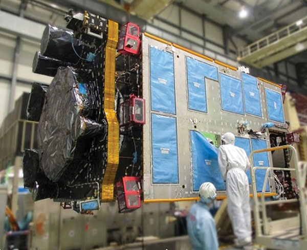
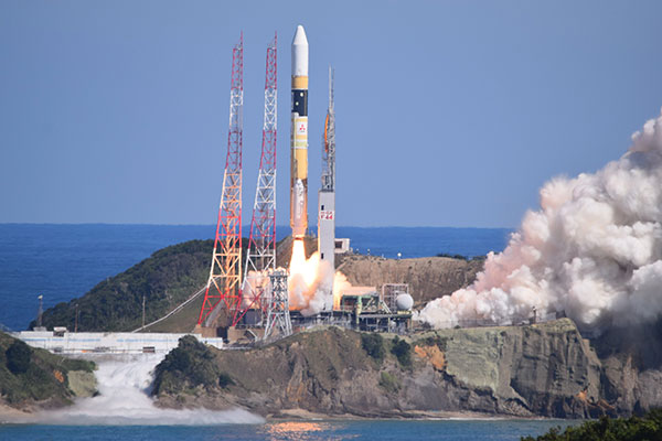
QZS-R1 is prepped for testing. At left is the Earth-oriented surface that hosts the L-band antenna. (Photo: JAXA)
By Peter Steigenberger, Steffen Thoelert, Sergei Yudanov and Markus Ramatschi
The Japanese QZS-1R satellite was launched on Oct. 26, 2021, from the Tanegashima Space Center in Japan. It serves as a replenishment for QZS-1, the first spacecraft of the Japanese Quasi-Zenith Satellite System (QZSS) in orbit since September 2010.
QZS-1R joins the current QZSS constellation of three satellites in inclined geosynchronous orbit (IGSO) and one geostationary satellite. These four Block I satellites transmit the L1C/A signal at 1575.42 MHz.
QZS-1R, as well as future QZSS satellites, are able to transmit the new L1C/B signal. L1C/B is based on the same family of gold codes as L1C/A, but uses a binary offset carrier (BOC) modulation instead of the binary phase-shift keying (BPSK) and a different PRN range (203–206).
Compared to BPSK, the BOC modulation adds a square wave subcarrier with a frequency of fsc = 1.023 MHz that equals the chipping rate of the ranging code. This subcarrier shifts the peak spectral energy from the center frequency fL1 to fL1 ± fsc to reduce interference with the GPS L1C/A signals.
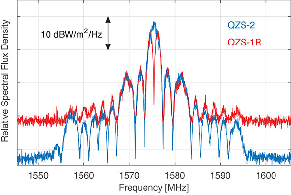
During in-orbit testing (IOT) from late November until early December 2021, QZS-1R transmitted L1C/A and L1C/B signals intermittently. FIGURE 1 shows a spectrum of the L1-band transmissions of QZS-1R recorded on Nov. 25 with the 30-meter dish antenna of the German Space Operations Center in Weilheim, Germany, as well as a spectrum of QZS-2 recorded in July 2017.
Figure 1. L1 spectra of QZS-1R (red) transmitting L1C/B and L1C, as well as QZS-2 (blue) transmitting L1C/A and L1C. The spectra were measured with DLR’s 30-meter high-gain antenna on Nov. 25, 2021, and July 20, 2017, respectively. (Credit: DLR)
During IOT, QZS-1R had an extremely low maximum elevation of 0.8° in Weilheim. Due to technical restrictions for such low elevations, QZS-1R had to be observed with a sidelobe of the 30-meter antenna. As a result, the respective observations are much more noisy than the QZS-2 reference data.
Nevertheless, the different spectral characteristics of L1C/B and L1C/A can be clearly seen in FIGURE 1: L1C/B has two maxima at 1574.4 and 1576.5 MHz due to the BOC modulation, whereas the BPSK L1C/A signal has one maximum at the center frequency of 1575.42 MHz.
GNSS receivers of the International GNSS Service (IGS) started to track L1C/A, L1C, L2C and L5 signals of QZS-1R on Nov. 17. Aside from the regular PRN code J04, test signals using the non-standard code PRN J06 were intermittently transmitted by QZS-1R during the IOT and tracked by these receivers.
Based on the public specification of the new L1C/B signal, Javad GNSS developed a prototype firmware that enabled tracking of this signal during the early transmissions. This firmware was installed on a Javad TRE-3 receiver operated by GFZ German Research Centre for Geosciences at its IGS station WUH200CHN in Wuhan, China.
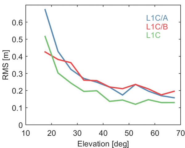
FIGURE 2 illustrates the noise and multipath characteristics of different QZS-1R pseudorange measurements. It is based on the so-called multipath linear combination of L1 pseudorange and L1/L2 carrier-phase observations covering a six-hour data arc. RMS values were computed for 5-degree elevation bins for each pseudorange signal. While the individual signals were tracked on different days of the IOT and the associated results have to be interpreted with care, the data indicate a very similar ranging performance of the legacy C/A signal and the new C/B signal. Best results are obtained with the L1C signal, which uses both a higher signal power and an advanced modulation with superior multipath suppression.
Figure 2. Noise and multipath characteristics of QZS-1R signals on the L1 frequency tracked by the IGS station WUH200CHN in Wuhan, China. (Credit: DLR)
QZS-1R will resume continuous transmission of L1C/A as soon as declared healthy. The transition from L1C/A to L1C/B is planned for 2023-2024, when an operational QZSS constellation of seven satellites is reached. The launches of the IGSO satellite QZS-5, the geostationary QZS-6, and the quasi-geostationary QZS-7 are all planned for 2023.
GNSS data used in this article were collected with a Javad GNSS TRE-3 receiver. The spectral overviews were captured with a Rohde & Schwarz FSQ26 signal analyzer.
Peter Steigenberger is a senior scientist at the German Space Operations Center of the German Aerospace Center (DLR), where he conducts research in the field of new satellite navigation systems.
Steffen Thoelert is an electrical engineer at DLR’s Institute of Communications and Navigation. His research activities focus on signal-quality monitoring and satellite payload characterization.
Sergei Yudanov is a senior firmware developer at Javad GNSS, Moscow. His main field of activity is GNSS signal processing.
Markus Ramatschi is a senior scientist at the Helmholtz Centre Potsdam, GFZ German Research Centre for Geoscience. He is operating a global GNSS reference station network.
Ramatschi M., Bradke M., Nischan T., Männel B. (2019): “GNSS data of the global GFZ tracking network,” vol 1. GFZ Data Services. https://doi.org/10.5880/GFZ.1.1.2020.001
By Satoshi Kogure Director, National Space Policy Secretariat Cabinet Office, Japan/QZSS Strategy Office
At 02:19:37 UTC on Oct. 26, 2021, a new satellite in the QZSS constellation — QZS-1R — was launched from the Tanegashima Space Center in Japan. It is the fifth satellite in the constellation and the replacement of the first satellite, launched in September 2010.
As of December 2021, initial on-orbit testing (IOT) and tuning of the precise orbit determination (POD) function in the ground control segment was ongoing. QZS-1R is the first QZSS satellite that will transmit the L1 C/B signal, splitting the power spectrum at the L1 center frequency by adopting BOC modulation on the existing C/A signal, to mitigate interference into the GPS L1 C/A signal. C/B signal transmission was verified during the IOT phase. QZS-1R will transmit the C/A signal continuously until QZS-5, 6 and 7 are launched and the noise floor increased.
The launch of QZS-1R was a milestone toward a sustainable national infrastructure for Japan. The Japanese government’s Cabinet Office (CAO) is trying to establish more secure positioning, navigation and timing (PNT) services by deploying seven satellites for the QZSS constellation. It will add three satellites to the current four around 2023.
This will give QZSS an independent PNT capability and enhance GNSS performance as well as robustness, and cover a broader area in the Asia Pacific region. CAO is still investigating the future of the QZSS constellation, including its final configuration and how to provide assured PNT services corresponding to future user requirements. However, it is thought that the full operational capability for Japan at minimum may be declared after the completion of the initial seven-satellite constellation.
Today, QZSS is providing ranging signals on L1C/A, L1C, L2C and L5 for all users able to acquire and track those signals. Those signals have the same RF properties and almost the same message format as the corresponding GPS signals — they are interoperable.
In addition, a unique characteristic of QZSS is that it transmits error correction messages available in Japan on separate channels — L1S, L1Sb and L6 — from those used to broadcast its ranging signals. Messaging functions are also provided through QZSS L1S and S-band two-way communication links on QZS-3 in support of disaster mitigation and relief operations in Japan.
CAO launched the QZSS operational services using a four-satellite constellation on Nov. 1, 2018. Its first three years of operation have provided much knowledge to improve their performance. The averaged signal-in-space user ranging error, a 95 percentile daily statistic, has been improved and achieved less than 1.0 meter, while the specification is 2.6 meters; the best daily value in the evaluation period (Aug. 31, 2020 to Sept. 1, 2021) was less than 0.5 meter for QZS-1, 2 and 3.
This remarkable improvement was shown on the Centimeter Level Augmentation Service (CLAS). According to the original design of CLAS, transmitted error corrections were for only 11 satellites in the GPS, QZSS and Galileo constellations. After two years of initial operation, we updated the ground control segment for CLAS to increase the number of augmented satellites from 11 to a maximum of 17. This increase in the number of satellites with error corrections leads to excellent improvement of CLAS performance in more challenging user environments such as urban and mountainous areas.
To improve the service performance further and measure new observables for satellite orbit clock estimation, inter-satellite ranging and two-way ranging functions between tracking station and satellite will be developed for QZS-5 to -7 and following satellites. The ground control segment will also be updated.
Multi-GNSS ADvanced Orbit and Clock Augmentation (MADOCA) precise point positioning (PPP) will be implemented as a practical service no later than 2024. It is aiming to provide decimeter-level PPP service with broadcast of globally available satellite orbit and clock error corrections as well as code-phase and carrier-phase biases.
PPP has a well-known disadvantage: long convergence time. By using the marginal L6D channel on QZS-5 to -7, the ionospheric delay correction for wide area will be distributed. CAO will try to evaluate how such ionospheric correction could reduce the initial convergence time for the PPP calculation. In an experiment planned in collaboration with Asian Pacific countries, regional stations in the nationwide CORS network will be used for generating such corrections.
Early or Emergency Warning Service (EWS) is also expanding its service coverage into the region. The common EWS format is being jointly investigated by India, the European Union and Japan under the UN-ICG framework. The QZSS EWS for the Asia Pacific region through the L1S signal on QZS-1R, 2, 3 and 4 will be established after completion of a ground segment update around 2024.
In January’s issue, he listed 10 questions from a PNT expert perhaps unfamiliar with eLoran.
These are important questions that must be asked of any technology, especially one under consideration to augment and back up our essential, but very weak and vulnerable, GNSS signals.
Yet the expert’s concerns pale in comparison to the essential questions about GNSS and PNT facing the United States and the West.
While I look forward to answers to the “10 questions” as a part of our ongoing professional dialogue, there are two important points of context we all need to keep in mind.
A Broad Consensus
First, Mr. Luccio’s assertion about eLoran being a part of the solution is more than reasonable. It also has a lot of impressive support from a wide variety of authoritative sources.
In 2008 and 2015, after much study each time, the U.S. government decided on and committed to building eLoran systems. Also, the U.S. government-sponsored National Space-based Positioning, Navigation and Timing (PNT) Advisory Board recommended eLoran in 2010 and 2018 as a part of securing the nation’s critical PNT capability.
In 2021, the U.S. Department of Transportation told Congress that wide-area terrestrial broadcast was a necessary part of a national PNT architecture. They later commented that infrastructure required per coverage area would be a key selection criterion for that broadcast technology. In other words, a system like eLoran.
Overseas, support for Mr. Luccio’s statement on eLoran is even stronger.
The United Kingdom has long endorsed eLoran and operates an eLoran transmitter as a timing reference.
Russia operates Chayka, a version of Loran.
Available information points to Iran’s terrestrial PNT system being a form of Loran or eLoran.
China and South Korea have long had Loran-C systems, and both are in the process of upgrading to the eLoran standard.
Each of these countries has publicly announced that it operates Loran/eLoran as a matter of national security in case space-based systems are jammed or destroyed, and to generally avoid overdependence on space-based PNT signals.
So, Mr. Luccio’s assertion was not at all revolutionary. Given all the studies, recommendations and existing uses, it would be surprising if he did not consider eLoran a part of the solution.
The Important Questions
Second, modern keying, encryption, authentication and other tech advances will help make all PNT technologies much safer and more resilient than they would have been decades ago, Loran and eLoran included.
Yet all will still have their strengths and weaknesses.
The most important questions we must ask are about how to establish the right level of national PNT security. These include:
What is the right combination of technologies and systems with different delivery and failure modes that complement and reinforce GNSS and each other?
How can the systems be efficiently and effectively implemented?
How can the services they provide be easily accessed and widely adopted to ensure all parts of society are protected?
Countries such as China have answered these questions and are well down the path to implementation and wide adoption. Their robust national PNT architectures support easier rollout of 5G, rural broadband and other systems. They also serve as solid tech infrastructure upon which to build myriads of technologies and applications yet to be conceived.
Those nations not so advanced must accelerate their efforts. Otherwise, they must resign themselves to perpetually coping with GNSS vulnerabilities, including the possibility of attacks, and an eventual second or third place in the world because of their shortsightedness.
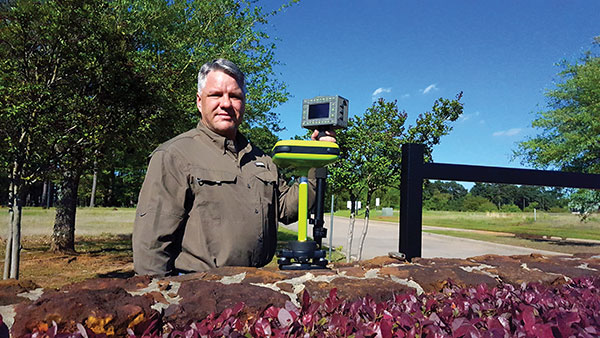
Shawn Billings, RPLS, reinvests some of his profits in surveying gear, like this JAVAD GNSS unit. (Photo: Rebecca Billings)
By Shawn Billings RPLS, Proprietor, Pendulum Surveying and Dealer
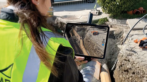
The AEC industry relies on surveyors to be a bridge between the existing landscape and the design landscape. Surveyors have been providing virtual reality for centuries, albeit in a mostly analog way, until very recently.
Imagine that a school board needs a new school. It describes the need to an architectural or civil engineering company, which develops a conceptualized plan. Next, it is time to figure out how to adapt this rough concept to the real world. Will the school fit within the boundaries of its district’s property? How will it access public rights-of-way? Can the current roads accommodate the traffic it will bring? How will the school access utilities? How will the building impact existing stormwater drainage? How do various data collected by others (such as geotechnical and wetlands delineation) fit into the site plan?
The data collected by the surveyor inform the designer, usually in the form of a map — historically on paper, but now in digital form. Most designers want the key features extracted rather than a dense point cloud, so it is important for surveyors to be able to understand what those key features are.
AEC surveying differs from boundary surveying in several ways. First, it usually requires consideration of a 3D world, not only two dimensions. Secondly, it will usually involve many thousands of points, not a few tens of points as is usually the case in boundary surveying. Third, AEC surveying will typically involve many more stakeholders. Fourth, the liability in AEC surveying will usually (but not always) be greater because of the significant costs involved.
AEC surveying can be challenging because the timeframes are typically tight, with numerous professionals involved. Surveyors will often have to wait on others one day, only to be rushed the next day once the ball moves into their court. However, the tools available to us today allow us to collect data much more quickly than we ever could before.
Today, I can carry almost everything I need to survey in a compact car—my Javad GNSS real-time kinematic (RTK) system, my robotic total station, my handheld electronic distance measuring device, my laptop computer, my smartphone (which provides internet access), my digital camera, my lidar and my photogrammetric drone, as well as the accessories needed for each device. All these devices have become more portable, more powerful, and less expensive. The gains in efficiency have reduced fieldwork by more than half over the past couple of decades, requiring fewer people and generally providing much better quality data.
Today, it is rare for a surveyor to provide paper deliverables to designers. Almost all prefer digital files, usually vector data in DWG or DGN format along with surfaces in XML format.
Recently, I have worked on several small commercial building projects. The requirements were the same for each. The initial survey includes (among other things):
a title boundary survey
the location of existing utilities and structures
contours at one-foot intervals
the delineation of the floodplain, if present on the site
the location of streets and other public access.
Once the initial survey is complete, I often set control for machine control, which heavy machinery uses to perform grading without requiring stakes. Once grading is complete, I often stake out building locations and sometimes paving.
Challenges have included working with city planners who do not always have the same sense of urgency as the project developers and designers.
Perhaps the greatest lesson I have learned is the importance of being efficient without being in a hurry, which breeds mistakes, such as missing important details or breaching a safety protocol and causing a serious injury.
I also have learned that while technology can increase profits, it is important to reinvest some of them into improving my work product. This way, I enjoy a better return on my investment, but I also enjoy a better deliverable for my clients.
Guangzhou Asensing Technology Co. Ltd, which specializes in high-precision positioning technology for intelligent transportation, demonstrated HD-MapBox at the Consumer Electronics Show (CES), which took place Jan. 5-8 in Las Vegas.
HD-MapBox integrates high-precision map data based on high-precision positioning.
The device can achieve lane-level positioning and 1+ mile (2 km) predictive cruise control (PCC), providing a decision basis for advanced assisted driving to better meet the demanding positioning requirements of autonomous vehicles.
“As the premise for autonomous driving safety, high-precision positioning is of great importance for integrating positioning technology based on inertial measurement units (IMU), GNSS signals, visual perception systems and high-definition (HD) maps,” said Situ Chunhui, Asensing Technology CTO. “High-precision positioning is becoming the preferred choice due to higher positioning accuracy and improved redundancy as well as an enhanced passing rate under all scenarios.”
Under any driving scenario, autonomous vehicles must accurately interpret their own lane-level location information to better predict and prevent risks and make safe driving decisions. As a result, positioning is not only part of the autonomous driving process, but also the premise of autonomous driving.
However, any single positioning technology has its own limitations, especially in certain scenarios such as in tunnels and underground garages where the perception system may be adversely affected by changes in the amount of light and low GPS signal, thereby affecting driving safety.
Fusing data from a GNSS receiver, IMU, ADAS camera, vehicle dynamics and HD maps, the HD-MapBox can achieve a lateral error of less than 8 inches (0.2 meters) and a longitudinal error of less than 6.5 feet (2 meters) with a 95 percent confidence interval, providing an accurate reference for highway pilot (HWP) and automated valet parking (AVP). Even if both GNSS and lane line detection are not available, the HD-MapBox can still enable vehicles to keep in lane for at least a quarter mile (400 meters).
How Inertial Systems and GNSS Availability Will Help
Innovation Insights with Richard Langley
ARE WE THERE YET? This was a familiar refrain from the backseats of parents’ cars when traveling to a holiday destination or to grandparents when I was growing up. We didn’t have videos on a display attached to the seats in front of us or (who could imagine?) our own personal communication device on which we could call up games, movies or social media channels.
But I’m not talking about that complaint from our childhoods. I’m asking if we have arrived at the era of the self-driving car. The answer is yes and no. It all depends on what you mean by “self-driving.” We reviewed some of the technologies needed for self-driving or autonomous vehicles in this column in June 2019. And we indicated in the introduction to that column that vehicle autonomy has several levels. SAE International, formerly known as the Society of Automotive Engineers, has defined six levels of autonomy that can be briefly described as Level 0 – no automation; Level 1 – hands on/shared control; Level 2 – hands off; Level 3 – eyes off; Level 4 – mind off; and Level 5 – steering wheel optional.
Already, Level 1 automation is widely available in modern cars with adaptive cruise control, parking assistance, lane-keeping assistance and automatic emergency braking among the features being offered. Level 2 automation, where the automated system takes full control of the vehicle’s acceleration, braking and steering, is available in some production models, although the “hands-off” designation is not to be taken literally — most motor vehicle laws require drivers to keep their hands on the steering wheel. Between Level 2 and Level 3, we have conditional automation — the car can drive itself, but the driver must stay alert and be prepared to take over immediately. Level 3 is high automation, where a computer fully drives the car at certain times on certain routes such as a highway; while the driver can perform other tasks such as reading a book, they must be prepared to take over operation of the vehicle within a few seconds if alerted by the automated system. While test campaigns are still ongoing, some jurisdictions permit Level 3 operation by ordinary drivers on some roads, and customers will soon be able to buy vehicles with this level of automation. Widespread use of Level 4 and Level 5 automation is further off (some would say quite a way off) and remains in development. But famously, last year, Toyota operated Level 4 self-driving shuttle vehicles around the Tokyo 2020 Olympic Village.
A lot more work needs to be done before we will have arrived at the era of the fully self-driving car that will be able to travel on any road, anywhere in the world, all year around, in all weather conditions. In particular, self-driving cars in urban environments (as opposed to highway driving) can be problematic. The required multi-sensor automated systems will include GNSS, but buildings block and reflect GNSS signals, reducing system availability and accuracy. In “Innovation” this month, researchers from the Illinois Institute of Technology report on how inertial navigation systems coupled with wheel-speed sensors and vehicle dynamic constraints can help.
By Kana Nagai, Matthew Spenko, Ron Henderson and Boris Pervan
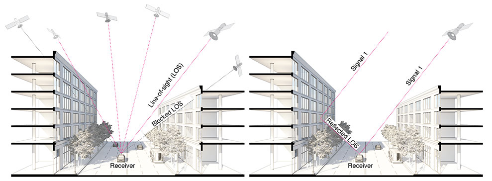
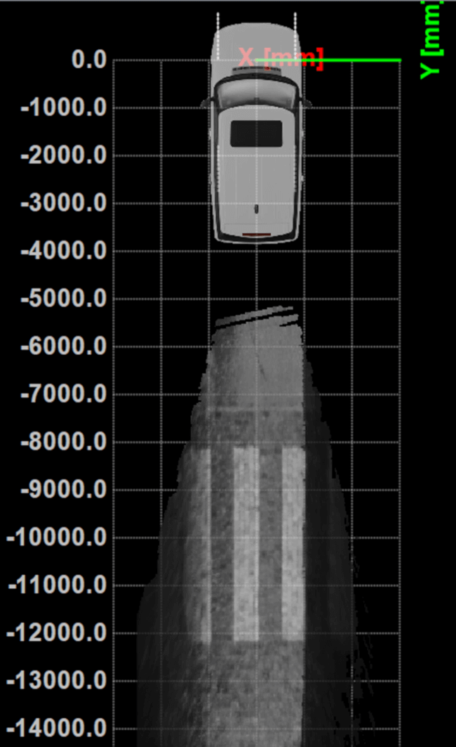
GNSS provides navigation services globally, but satellite visibility in urban areas is limited by high-rise buildings. This creates a mixture of GNSS available and denied environments (see FIGURE 1) — users do not generally know where the system can maintain sufficient levels of accuracy and integrity for a particular application. To begin to address the issue for self-driving cars, we evaluated GNSS-only availability in downtown Chicago.
FIGURE 1 . The figure depicts three types of potential GNSS signal reception: direct LOS signals and blocked LOS signals (left) and reflected LOS signals (right). (Image: Authors)
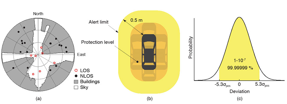
GNSS signal prediction in urban environments has been conducted in previous work. For example, the concept of “shadow matching” was developed to identify GNSS signal blockages in urban canyons. Overlaying sky plots on a hemispherical sky view can be used to distinguish between line-of-sight (LOS) and non-line-of-sight (NLOS) signals (see FIGURE 2a). Reflected rays can be predicted using Householder transformations to reveal potential multipath conditions. Satellites producing blocked or reflected (NLOS) signals should be excluded to maintain integrity.
FIGURE 2. (a) A hemispherical sky view in an urban environment. (b) Illustration of a protection level and an alert limit. To ensure integrity, the protection level must not exceed an alert limit. (c) The allowable probability of exceedance is assumed to be 10−7 in this work. (Image: Authors)
When the number of visible satellites is greater than three, GNSS can resolve vehicle position. However, even in cases where enough satellites are visible, the satellite geometries are generally weak because the dilution of precision (DOP) is adversely affected by the buildings partially blocking the sky. Horizontal positioning error must be bounded by a protection level computed by the vehicle. Then, for navigation to be deemed available, the protection level must not exceed a required alert limit (see FIGURE 2b). The maximum allowed probability of exceedance (see FIGURE 2c) and the alert limit can together be used to determine the maximum allowable position error standard deviation.
Even if the protection level is far below the alert limit in an open-sky environment, it will frequently exceed the alert limit once the vehicle enters a city. GNSS alone is generally not able to maintain availability, so integration with other sensors is needed. Tightly coupling inertial navigation systems (INS) with GNSS using the extended Kalman filter (EKF) provides better estimation in urban environments. The EKF algorithm also enables integration of wheel-speed sensors and vehicle dynamic constraints. These integrated navigation systems will improve availability, but it is still unclear how long such a system can be expected to maintain fault-free integrity in a congested city.
Focusing on the problem of self-driving cars in urban environments, we evaluate protection levels of navigation with practical integrated sensors: GNSS, INS, a wheel-speed sensor (WSS) and vehicle dynamic constraints (VDC). The goal is to develop the means by which we can determine locations where external ranging sources (such as lidar) are needed to maintain continuous navigation with fault-free integrity.
GNSS-ONLY AVAILABILITY
For GNSS availability evaluation, we assume an integrity requirement that the probability of exceeding a 0.5-meter alert limit must be lower than 10−7. The 0.5-meter alert limit therefore corresponds to approximately five times the position standard deviation, so the maximum allowable position error standard deviation is then approximately 0.1 meters. Accuracy at this level clearly requires differential GNSS carrier-phase measurements. We assume a nominal GNSS double difference (DD) carrier ranging error standard deviation of approximately 0.02 meters, and that carrier cycle ambiguities can be readily resolved in an open-sky environment prior to initiation of vehicle motion.
Given the assumptions made of the maximum allowable position error standard deviation and the GNSS ranging error standard deviation, the maximum allowable horizontal dilution of precision (HDOP) is about 5.
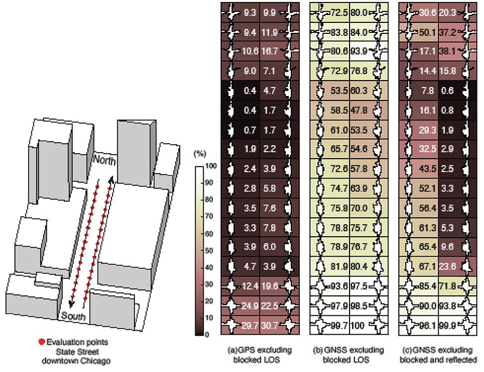
FIGURE 3 shows GPS and GNSS availability — the fraction of time the HDOP requirement is met over 24 hours — along a section of State Street in downtown Chicago. The availability results using GPS only and excluding only blocked LOS signals ranged from 0% to 9% along the block and 9% to 30% at the intersections (see FIGURE 3a). Using four full GNSS constellations (GPS, Galileo, GLONASS and BeiDou), availability ranged from 48% to 82% along the block and 72% to 100% at the intersections (see FIGURE 3b).
FIGURE 3. The percentage of GPS or GNSS availability in 3D-mapped downtown Chicago. We exclude satellites producing blocked LOS signals or both blocked and reflected LOS (NLOS) signals from the measurements. Each column expresses a lane of southbound or northbound travel. The availability is the percentage of total time when HDOP meets the self-driving car integrity requirements in 24 hours. (Image: Authors)
When we also excluded satellites producing reflected LOS signals that reach the vehicle, the availability dropped significantly at every point (see FIGURE 3c). We assert that FIGURE 3c expresses the reality of GNSS availability because building-reflected multipath signals degrade positioning accuracy and would affect integrity negatively. It’s obvious from these results that GNSS alone is insufficient to meet the autonomous driving requirements in an urban environment, and multi-sensor integrated navigation systems are needed to augment poor GNSS signal availability.
MULTI-SENSOR INTEGRATION
We begin by considering tightly coupled INS/GNSS integration using an EKF, and then integrate a realistic sensor suite including WSS and vehicle dynamic constraints that enforce resistance to lateral sliding and vertical movement. If it is known from another source that the vehicle is not moving (for example, it is in the parking gear), a static mode constraint (SMC) can also be applied.
INS/GNSS Integration. Tightly coupled INS/GNSS integration with an EKF uses the INS measurement to predict vehicle motion. The continuous process model uses a state vector having the position in the navigation frame, the velocity, the attitude, bias errors and cycle ambiguities, with the input vector having accelerometer-specific force measurement in the body frame and gyro-rotation-rate measurements. A white-noise vector drives the inertial measurement unit (IMU) states.
The GPS/GNSS measurement model includes the measurement vector having carrier and code phases, and the observation matrix containing LOS vectors and the vector of white receiver thermal noise.
INS/GNSS/WSS/VDC Integration. For the vehicle in motion, we developed a model consisting of a WSS measurement in the along-track direction, a non-holonomic constraint resisting lateral sliding, and a holonomic constraint on vertical movement (see FIGURE 4).
The INS/GNSS/WSS/VDC integration using the EKF consists of the process model and the measurement models.
INS/GNSS/SMC Integration. The static mode constraint provides zero-velocity measurements to the EKF measurement update to mitigate position error propagation. We use SMC only when it is known that the vehicle is not moving; for example, when the vehicle is in the parking gear.
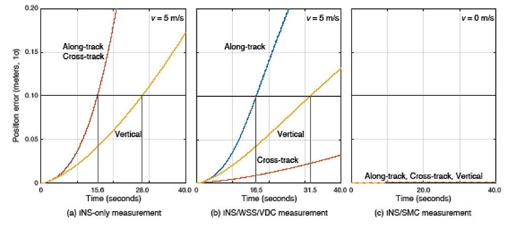
Error Propagation Analysis. We tested the time from perfect initialization to when position error exceeds 0.1 meters in GNSS-denied environments. FIGURE 5 shows the error growth in the along-track (x), the cross-track (y) and the vertical (z). The error specifications for a STIM300 tactical-grade IMU are used in this analysis. The standard deviation of the WSS measurement noise is assumed to be 0.05 meters per second, and the standard deviation of the movement constraint violations is 0.001 meters per second. The vehicle is moving at 5 meters per second except when we test the SMC.
FIGURE 5. The vehicle position error growth vs. time in the along-track (x), cross-track (y) and vertical (z) directions. Each graph represents the navigation system introduced in the multi-sensor integration section. The vehicle is moving at 5 meters per second (a and b) or 0 meters per second (c). (Image: Authors)
The INS can coast 15.6 seconds before the position error standard deviation exceeds 0.1 meters in both the along-track and the cross-track directions (see FIGURE 5a). The INS/WSS/VDC can coast 16.5 seconds in the along-track direction, and significantly more than 40 seconds (the simulation duration) in the cross-track direction (see FIGURE 5b). In static mode, INS/SMC estimate errors do not grow with time in any direction, as expected (see FIGURE 5c). In GNSS-denied environments, the non-holonomic constraint suppresses the cross-track position error, but the WSS measurement hardly affects the along-track position error. The SMC works perfectly, but the usage is limited to when the vehicle is known to be stationary.
SIMULATION SCENARIO
We imagine a future driverless-car mission scenario in which multi-sensor navigation systems are practicable. To minimize congestion in a city, autonomous vehicles will be held outside the urban core when not in use. In the clear open-sky environment, a vehicle in a parking lot completes GNSS initialization using the INS/GNSS/SMC system. Once requested for action, the vehicle departs for the city from the parking lot, and the motion of the vehicle improves alignment by the INS/GNSS system. Safe navigation can be ensured using the system to provide continuity under overpasses and bridges in the open-sky environment. Upon entering the urban core, navigation becomes more dependent on the INS/WSS/VDC system.
A reasonable numerical target for differential GNSS initialized position error is 0.02 meters, and for the INS alignment yaw angle error 0.1 degrees.
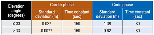
Local GNSS multipath errors from nearby vehicles will vary with the satellite elevation angle. Prior experimental results show that lower elevation-angle satellite signals (below 33 degrees) are much more likely to be impacted by multipath than higher ones (see TABLE 1).
TABLE 1. The nominal GNSS multipath error values in the simulation.
INITIALIZATION AND ALIGNMENT
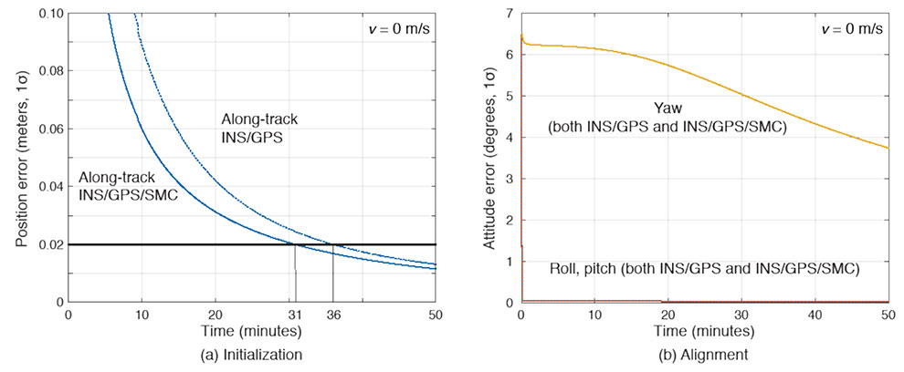
Initialization takes place in a parking lot with a clear sky view. A vehicle is in the parking gear, enabling SMC to be applied. FIGURE 6a shows a typical example: with INS/GPS/SMC, system initialization takes about 31 minutes, and with INS/GPS, about 36 minutes. Therefore, SMC does speed up GPS initialization, although the improvement is modest.
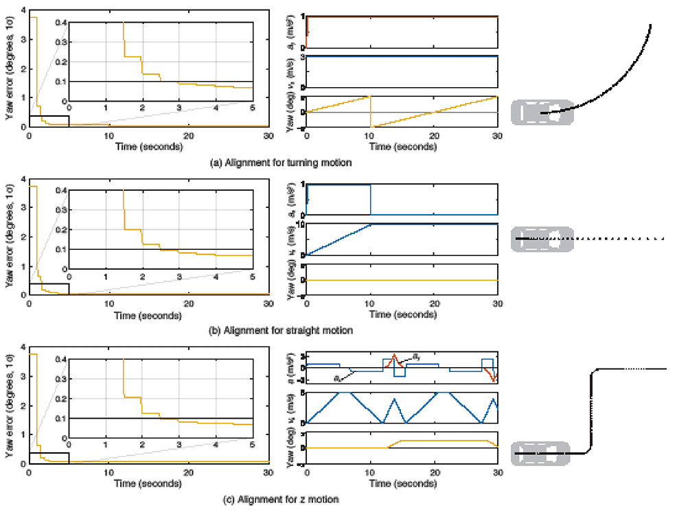
The yaw angle is not aligned during the initialization, but roll and pitch are immediately aligned (see FIGURE 6b). Earth’s gravity affects roll and pitch angle alignment but not yaw angle.
FIGURE 6. (a) Comparisons of initialization time between INS/GPS and INS/GPS/SMC in an open-sky environment. The INS/GPS/SMC system initializes rapidly. (b) Transitions of roll, pitch, yaw alignment during the initialization. Yaw angle alignment cannot be performed when the vehicle is stationary. (Image: Authors)
Yaw angle alignment cannot be performed when the vehicle is stationary or moving with constant velocity. Accelerated motion, either straight or turning, is required. FIGURE 7 shows the behavior of the yaw angle error standard deviation using the INS/GPS system when centripetal (see FIGURE 7a) or tangential (see FIGURE 7b) acceleration is applied. The yaw angle can be aligned in a couple of seconds for either type of acceleration. To represent typical initial motions of self-driving cars, we model a parking-lot departure via a “Z”-shaped path. In this scenario, the yaw alignment error reaches 0.1 degrees within a couple of seconds (see FIGURE 7c).
FIGURE 7. The behavior of yaw angle error when centripetal (a) or tangential (b) acceleration is applied; (c) shows the behavior while following a z-shaped path. The yaw angle can be aligned in a couple of seconds in each case. (Image: Author)
EVALUATION IN URBAN ENVIRONMENTS
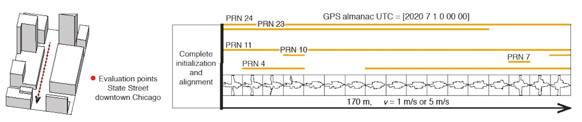
After initialization and alignment in the open-sky environment, we simulated the vehicle traveling into the urban core. The urban environment in our study is 3D-mapped State Street in Chicago, which runs north-south and transits from low-rise neighborhoods to central downtown. We selected one congested section surrounded by tall buildings and computed the position error standard deviation along the path. The evaluation points are at 10-meter intervals over a total distance of 170 meters. The yellow lines in FIGURE 8 denote the visible satellites, identified by their pseudorandom noise (PRN) code numbers, at each point. We assume for convenience that the INS/GPS system is initialized and aligned at the first evaluation point. In reality, we would expect a degraded initial condition because we are starting the simulation in an urban canyon.
FIGURE 8. Evaluation points and PRN numbers of visible satellites at each point. (Image: Author)
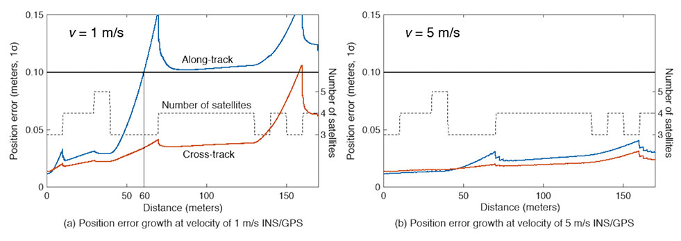
In the first simulation, the car equipped with the INS/GPS system moved either 1 or 5 meters per second. The y-axis in FIGURE 9 represents the position error standard deviation, and the x-axis represents the distance in meters. The dotted line expresses the number of visible satellites. The error when the vehicle velocity is 1 meter per second exceeded the maximum allowable position error standard deviation of 0.1 meter, at the distance of 60 meters. However, when the velocity was 5 meters per second, the maximum allowable position error standard deviation was never reached. It is also clear from the figures that error propagation is significantly affected by the number of visible satellites.
FIGURE 9. A comparison of position error growth between velocities of 1 meter per second and 5 meters per second. (Image: Author)
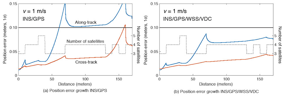
In the second simulation, we compared two different navigation systems, INS/GPS and INS/GPS/WSS/VDC. The vehicle moved at 1 meter per second in the same urban environment. The INS/GPS/WSS/VDC system does provide relief, but the error propagation is still clearly affected by the number of visible satellites (see FIGURE 10).
FIGURE 10. A comparison of position error growth between the INS/GPS and INS/GPS/WSS/VDC systems for a velocity of 1 meter per second. (Image: Authors)
In GNSS-challenged environments, INS error propagation is a function of time. When a vehicle moves faster, it clears the blockage area more quickly, reducing the impact of INS drift — a function of time, not distance. In contrast, GNSS error is completely determined by location. Because INS error propagation depends on how long the vehicle stays in an area of GNSS outage, protection levels for trips through the same area will be different if the vehicle is smoothly cruising or gets stuck in a traffic jam.
CONCLUSION
To gain a better understanding of how long and under what local conditions multi-sensor integrated navigation systems can maintain fault-free integrity, we evaluated navigation positioning errors in 3D-mapped downtown Chicago. The system we developed consists of sensors with which self-driving cars would reasonably be equipped: GNSS, INS, WSS and dynamic constraints. We showed that INS/GPS position errors along the path depend very strongly on the vehicle’s speed. When the system is augmented with WSS/VDC, position errors are suppressed, but the error propagation is still strongly influenced by the number of visible satellites.
ACKNOWLEDGMENTS
The research described in this article is supported by the National Science Foundation. Figure 1 was created by Alexis Arias of the Landscape Architecture + Urbanism Program at the Illinois Institute of Technology (IIT). The authors greatly appreciate the advice and help of Nilay Mistry from that program.
This article is based on the paper “Evaluating INS/GNSS Availability for Self-Driving Cars in Urban Environments” presented at ION ITM 2021, the virtual 2021 International Technical Meeting of The Institute of Navigation, Jan. 25–28, 2021.
KANA NAGAI is a Ph.D. candidate and research assistant in mechanical and aerospace engineering at IIT.
MATTHEW SPENKO is a professor of mechanical and aerospace engineering at IIT. He earned his M.S. and Ph.D. degrees in mechanical engineering from the Massachusetts Institute of Technology.
RON HENDERSON is a professor and director of the Landscape Architecture + Urbanism Program at IIT. He earned his Master of Landscape Architecture and Master of Architecture from the University of Pennsylvania.
BORIS PERVAN is a professor of mechanical and aerospace engineering at IIT. He earned his M.S. from the California Institute of Technology and Ph.D. from Stanford University.
For navigation and control of any robotic or autonomous outdoor system, GNSS and inertial navigation systems (INS) are key components. Inevitably, the question arises: Should you build your own custom solution or integrate an available GNSS/INS combined solution? What would give you the best performance, while keeping the total cost of ownership (TCO) to a minimum? The TCO is also known as the “long-term price” and is defined as the purchase price plus the costs of operation over time.
Xenomatix is a company offering automotive solutions based on lidar technology. With eight years of innovative experience, Xenomatix has installed a pre-integrated GNSS/INS receiver on its latest lidar product, achieving high GNSS/INS performance with minimal TCO.
In an integrated INS/GNSS receiver, the GNSS receiver provides positioning with centimeter-level accuracy. The other component is a micro-electromechanical inertial measurement unit (MEMS IMU), which measures 3D orientation in terms of heading, pitch and roll angles with sub-degree precision. For its latest product XenoTrack, Xenomatix chose an INS called XenoAsterx based on the AsteRx SBi3 from Septentrio, which it integrated alongside its lidar to collect road-quality data to the smallest detail.
From an in-house solution to a pre-integrated system
Three years ago, when Xenomatix started developing its new lidar road-inspection system, the company had a GPS receiver, an IMU and an odometer as accompanying sensors. The company wanted to expand into new markets of road inspection in accordance with international standards, and so it needed to improve its components to take the overall performance of its system to the next level with RTK high-accuracy positioning.
To achieve this, while saving time and costs, Xenomatix acquired an AsteRx SBi3 INS/GNSS receiver, which allowed it to focus on its core lidar technology and sensor-fusion algorithms.
This off-the-shelf INS/GNSS solution provided all the high-accuracy positioning and orientation information Xenomatix needed, while eliminating most costs of development, maintenance and support. The new receiver allowed them to drive for miles, without any offset in positioning, something impossible with the previous GPS receiver.
The unique technology from Xenomatix stitches images by using lidar point-cloud overlays. However, when the car is moving fast, this overlay is smaller. The pre-calibrated GNSS/INS extends system performance by allowing stitching even when driving at higher speeds.
“If we start driving and we stitch the road for tens of kilometers and we come back to the same starting point, then we see an offset of only a few millimeters,” said Filip Geuens, CEO, Xenomatix. “This is for us the strongest proof of accuracy and reliability of the GNSS sensor.“
Why pre-integrated GNSS/INS offers better value
The pre-integrated GNSS/INS allows XenoTrack to collect road data even at higher speeds. (Credit: Septentrio)
A pre-integrated GNSS/INS solution — versatile enough to fit into virtually any autonomous or mapping system — offers the best value in the long run for the following reasons.
Better performance. The manufacturer of a GNSS/INS solution specializes in fusing the GNSS receiver and the INS in an optimal way. To accomplish this, the sensors are synchronized and their output run through a sophisticated Kalman filter algorithm. The fused device is then fine-tuned for optimal operation under various conditions. Finally, it is extensively tested and validated.
While being used by numerous customers and in varying applications, the GNSS/INS solution proves itself on various levels such as accuracy and robustness. This results in superior performance, even in the most demanding environments.
After installing the AsteRx SBi3 GNSS/INS system, XenoTrack was able to extend its functionality to inspect longer distances of roads at higher speeds. The AsteRx SBi3 operates reliably, even in challenging environments, such as when driving near high cliffs or under bridges.
Less development time and lower costs. When building a system, the development time is usually about one year employing two full-time GNSS/INS specialists. Hardware components need to be integrated and synchronized, while various interfaces and the Kalman filter need to be implemented. Additional features may be developed, such as velocity input as well as tools for validation, before the intricate step of performance fine-tuning. Finally, additional testing efforts are needed for verification and validation of the device.
On the other hand, a pre-integrated GNSS/INS system with easily accessible interfaces and flexible configuration ensures quick installation, meaning the product is ready within weeks.
Lower maintenance costs and support. Certain high quality pre-integrated GNSS/INS receivers are future-proof — ready to use new GNSS satellite signals and services as soon as they become available. An example of such upcoming service is the Galileo OSNMA anti-spoofing authentication.
Some receiver manufacturers such as Septentrio also offer continuous product improvement in the form of free firmware updates. A system developed in-house, on the other hand, needs continuous investment to maintain its competitive edge.
When issues occur, Septentrio also offers local worldwide support, with experienced application engineers ready to solve GNSS, INS or coupling issues that could halt the production process. For example, when Xenomatix discovered that its GNSS/INS was not working optimally in a certain environment, the company called Septentrio. Within days application engineering experts who analyzed the logged data found the source of the issue and proposed a solution.
Focus on core technology. When the budget is limited, choices need to be made about where to focus the efforts. When a company saves on GNSS/INS development, more can be invested in core technology. This means avoiding any lost-opportunity costs and optimizing margins.
Building your own is not always the best option
Acquiring a pre-integrated GNSS/INS receiver allowed Xenomatix to have a superior and affordable product with a competitive edge. AsteRx SBi3 increased the performance of the XenoTrack mapping system, while a short integration period allowed a faster time-to-market.
Xenomatix also benefited from low maintenance costs, keeping overall TCO to a minimum. Since the company was not spending time developing a custom GNSS/INS system, it could focus fully on its core technology. This allowed Xenomatix to take its business to the next level at a high pace.
Award-winning technology
In November 2021, the XenoTrack road scanner, with AsteRx SBi3 inside, was announced a winner of the IRF Global Road Achievement Award for its innovative road scanning and surveying solutions.
A Nov. 17 webinar will focus on ways to deter attacks on and interference with GPS satellites and signals. The webinar takes place 2:30-3:30 p.m. EST; register for free.
Rep. John Garamendi (D-CA) will provide opening remarks for the webinar, which is co- sponsored by Domestic Preparedness Journal and the Resilient Navigation and Timing Foundation. Garamendi is the chair of the House Armed Services Readiness Subcommittee and has long been concerned about the vulnerability of America’s GPS.
“America’s over-reliance on GPS makes it a high priority target for a wide range of bad actors,” said Dana A. Goward, president of the Resilient Navigation and Timing Foundation and one of the webinar moderators. “And, since other nations, such as China, Russia and Iran, have terrestrial systems they can use when space is not available, the U.S. is at a strategic disadvantage.”
This “technology resilience gap” is one of several dangers that could lead to armed conflict that webinar panelist George Beebe discusses in his book The Russia Trap. His concern is that having such a pronounced relative weakness can invite meddling and exploitation by adversaries. Even if done on a small scale, this could lead to a series of escalating responses ending in an unintended, much more serious conflict that neither party wants.
Beebe is vice president and director of studies at the Center for the National Interest. He spent more than two decades in government service as an intelligence analyst, diplomat and policy advisor, including service as director of the CIA’s Russia analysis and as special advisor to Vice President Dick Cheney for Russia/Eurasia and Intelligence Programs.
Eliminating the gap between the United States and its adversaries is key to protecting GPS and the nation, according to webinar panelist Greg Winfree, director of the Texas A&M Transportation Institute. Winfree previously served as an assistant secretary for the U.S. Department of Transportation. While acknowledging there is no single answer, he has asserted that providing at least one alternative system will go a long way toward “getting the bullseye off GPS.”
The third webinar panelist, Scott Pace, has supported Winfree’s approach. Pace is the director of George Washington University’s Space Policy Institute and former executive director of the National Space Council. He has commented that having an alternative to GPS will contribute to national security and improve global stability. It will “lower the pressure on us to escalate and respond” should GPS satellites be damaged or services disrupted.
A roundup of recent products in the GNSS and inertial positioning industry from the November 2021 issue of GPS World magazine.
OEM
Simulator
Designed for desktop convenience
Photo: Orolia
The BroadSim Solo has a compact form factor designed to fit comfortably at a typical desk or workstation. It shares the same Skydel simulation engine that runs on a standard BroadSim, BroadSim Anechoic and BroadSim Wavefront. It supports advanced scenario creation features and the benefits provided by a software-defined architecture such as high dynamics, a 1000-Hz iteration update rate and ultra-low latency of 5 ms. Nearly all civilian GNSS signals can be generated through the Solo’s single RF output (one frequency band at a time), along with jamming or spoofing signals, and GPS AES M-code.
Series offers GNSS, 5G NR, and wifi-6E combination
Photo: 2J Antennas
The Stellar series of antennas is designed for a large suite of devices with a focus on GNSS, sub-6 GHz, 5G NR, 4G LTE, 3G, 2G and WiFi-6E technologies. The series is suitable for law enforcement, medical transportation, fire rescue and other mission-critical applications. The series includes single or up to 9-in-1 configuration choices within the range of 617 MHz to 7125 MHz frequency bands. The patent-pending technology reduces the antenna footprint by 55% while implementing a new double trifilar design and longitudinal resonances for MIMO/ARRAY configurations that traditionally have more complex size restrictions (such as B71 band/600 MHz). Each antenna configuration uses symmetrical or asymmetrical resonators for negative sections of the antenna, resulting in maximum performance at low and mid frequencies.
The full-band GNSS HC990E embedded helical antenna is designed for precise positioning, covering the GPS/QZSS-L1/L2/L5, QZSS-L6, GLONASS-G1/G2/G3, Galileo-E1/E5a/E5b/E6, BeiDou-B1/B2/B2a/B3, and NavIC-L5 frequency bands, including the satellite-based augmentation system (SBAS) available in the region of operation [WAAS (North America), EGNOS (Europe), MSAS (Japan), or GAGAN (India)], as well as L-band correction services. The HC990E embedded helical antenna is designed and built for high-accuracy positioning. It is packaged in a very light and compact form factor, making it suitable for a wide variety of applications, especially lightweight UAV navigation. The HC990E is 60-mm wide and 25-mm tall, weighing 12 grams. It features a precision-tuned helical element that provides an excellent axial ratio and operates without the requirement of a ground plane. The HC990E also features a low-current, low-noise amplifier (LNA) and pre-filter to prevent harmonic interference from high-amplitude signals, such as 700 MHz band LTE and other nearby in-band cellular signals.
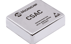
The SA65 chip-scale atomic clock (CSAC) provides precise timing accuracy and stability in extreme environments. Designed for military and industrial systems, it features ultra-high precision and low power consumption. The SA65 CSAC delivers higher performance than the previous SA.45s CSAC, including double the frequency stability over a wider temperature range and faster warm-up from cold temperatures. It has an operating temperature range of –40° C to 80° C and a storage temperature range of –55° C to 105° C. The warm-up time of two minutes at –40° C is 33% faster than that of the SA.45s. These performance improvements benefit designers of highly portable solutions for military applications such as assured positioning, navigation and timing (A-PNT) and C5ISR (command, control, communications, computers, cyber, intelligence, surveillance and reconnaissance).
Samsung Electronics is offering a new processor for wearables, the Exynos W920. The new processor integrates an LTE modem and is built with an advanced 5-nanometer (nm) extreme ultraviolet process node, offering powerful yet efficient performance demanded by next-generation wearable devices. The Exynos W920 is embedded with a GNSS L1 receiver (GPS, GLONASS, BeiDou, Galileo) for tracking speed, distance and elevation during outdoor activities. It also has a 4G LTE Cat. 4 modem. It has two Arm Cortex-A55 cores for high-performing, power-efficient processing and an Arm Mali-G68 GPU with CPU performance improved by 20% and 10 times better graphics performance than its predecessor. The Exynos W920 supports a new unified wearable platform that Samsung built jointly with Google, and will be first applied to the upcoming Galaxy Watch model.
The Arrow Gold+ and Arrow 100+ expand upon the features of the Arrow Gold and Arrow 100. The Arrow Gold+ has a battery life 3.5 hours longer, for a total of 11 hours of field autonomy. It supports concurrent use of BeiDou B3 and GPS L5 signals when using RTK corrections, and the upcoming Galileo E6 High-Accuracy Service (HAS). The Arrow 100+ has a battery life 6 hours longer than the Arrow 100, for a total of 18 hours of field autonomy. It also supports Atlas H50 (Basic) service subscriptions, which provide 30-50 cm positioning accuracy worldwide when no SBAS or RTK network is available. Both the Arrow Gold+ and Arrow 100+ use Eos Bridge to connect with external sensors — multiple mobile devices can connect to a single Arrow GNSS receiver via Bluetooth.
EagleView’s high-resolution ortho and oblique imagery now can be converted into 3D mesh layers with Skyline’s PhotoMesh and viewed, edited and analyzed on Skyline’s TerraExplorer platform. EagleView customers will be able to use Skyline’s TerraExplorer web-based GIS viewer and editor to see, analyze and share their imagery in an immersive environment. Accurately measuring distance, area and volume is now easier than ever, which is critical for planning and zoning to verify regulations or estimate the costs of flattening a site. With floodplain analysis, disaster management can identify flood risks before they happen, and with viewshed calculations E911 can pre-plan for high-profile events. Other key analytic features for customers include the ability to analyze shade, view contour and slope maps, and view in underground mode. The additional 3D Mesh capability is available as an add-on to any new Reveal Essentials+ Property or Neighborhood image capture.
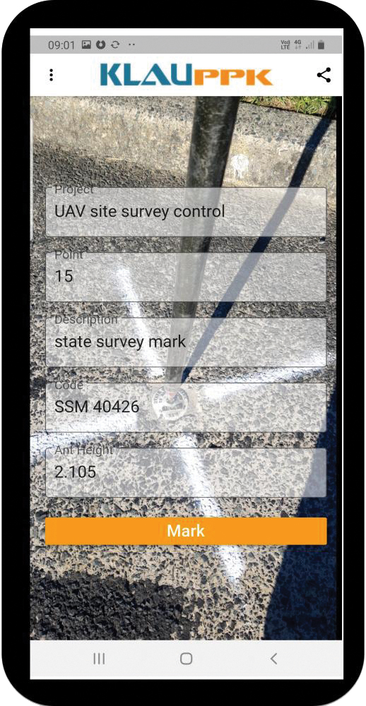
The KlauPPK Phone App, designed for use on drones with KlauPPK hardware and software, enables users to collect ground survey points with a name, description, feature code and antenna height like a traditional survey controller. The app sends the information to the operator’s computer for processing with the raw GNSS data logged in the KlauPPK unit on the pole. After post processing, the accurate survey data can be brought into CAD software to create points and line strings. The app takes a photo of the point being captured, and metadata is collected in the project. Users can place ground control points or check points, pick up as-built data like roads and utilities, and perform basic surveying. The system is compatible with the hybrid PPP/PPK MakeItAccurate post-processing service.
TerraLens 9.3 is a real-time software development toolkit for geospatial visualization. This release improves performance for 3D visualization for large viewports and multi-domain visualization features for command-and-control applications. It is significantly faster to enhance situational awareness. With increased multithreading in its map handling, TerraLens can load and display vector, raster and elevation formats smoothly without pre-processing, suitable for applications with disk size constraints or customers with a short turn-around time. A pre-processing option is still included. Improved data culling ensures only visible items will be rendered — especially noticeable when displaying large numbers of dynamic tracks and objects. New tools and features including support for OGC 3D Tiles for cityscapes, and a new API to control resolution of terrain mesh. Elevation warnings can now be displayed.
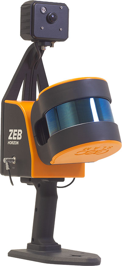
The ZEB Vision 16MP panoramic camera is now available for pre-order. Suitable for any ZEB Horizon, the new camera provides better colorization, image walkthroughs and point-cloud measurements using optional Draw software. Further updates mean GeoSLAM customers now can take a ZEB Horizon from handheld to UAV usage to get a more complete picture of projects. ZEB Horizon is compatible with the DJI Matrice 300 UAV.
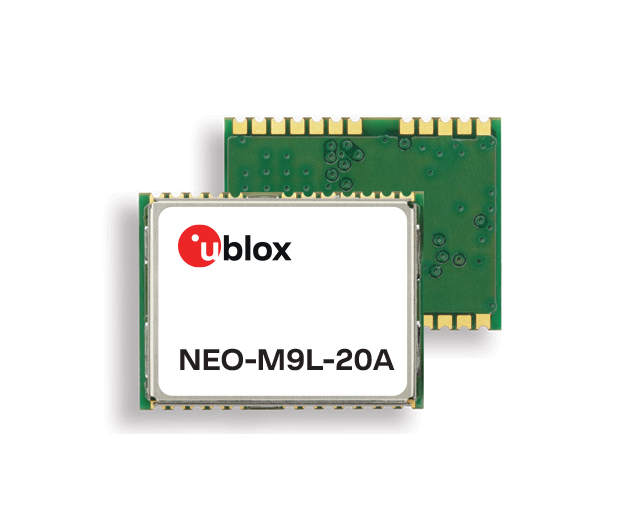
A new series of automotive-grade positioning modules are operational up to 105° C (221° F). The NEO-M9L modules and the M9140-KA-DR chip are built on the u-blox M9 GNSS platform and use dead-reckoning techniques to provide accurate position data when satellite signals are compromised or unavailable. The NEO-M9L-20A and NEO-M9L-01A modules, as well as the M9140-KA-DR chip, are specially designed for first-mount automotive solutions. The NEO-M9L-01A variant offers an extended operational temperature range up to 105° C, making it suitable for integration on the roof, behind the windscreen, or inside hot electronics control units. Applications include integrated navigation systems such as in-vehicle infotainment (IVI) and head units, integrated telematics control units and V2X.
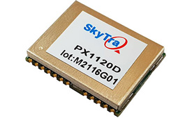
Provides positioning accuracy in tunnels, parking garages
Photo: SkyTraq
The PX1120D GNSS/inertial measurement unit (IMU) is suitable for both automotive pre-installation and aftermarket. The robust dead-reckoning module integrates a six-axis IMU and a concurrent quad-GNSS chipset. It receives signals from GPS, GLONASS, Galileo and BeiDou, as well as QZSS. The sensor-fusion module maximizes positioning accuracy in challenging environments, providing continuous navigation in tunnels and underground parking lots. For automotive pre-installation applications where vehicle wheel-tick signals are available, the PX1120D provides wheel-tick sensor fusion with automotive dead-reckoning. In aftermarket applications where wheel-tick signals are unavailable, the PX1120D provides an untethered dead-reckoning sensor-fusion solution. A single PX1120D module provides both automotive and untethered dead-reckoning functionality, simplifying logistics. It is suitable for infotainment systems, telematics control units, vehicle tracking, and advanced driver-assistance systems.
The Trooper Max 5G FR1 antenna platform is a 5G configurable and low-profile antenna platform for intelligent transportation and public safety applications. Configurable and optimized for multiband applications, the platform includes an option to add land mobile radio connectivity through an external whip port. With a slender shark-fin form factor, the Trooper Max is recommended for installation on public safety fleets. It is compatible with cellular routers supporting 600-MHz to 6-GHz frequencies. It also covers Wi-Fi 6 frequency ranges.
Version 7.9 of the CompassTrac fleet and asset management solution provides winter fleets with more detailed spreader controller information and greater insight through enhanced dashboard and reporting functions. Features include integration of numerous spreader controllers for granular, pre-wet and liquid materials; a snow-fighting dashboard consolidating key performance indicators; and a snow materials report that delivers historical reporting of granular, pre-wet and direct liquid material application rates and totals, including air and road temperature (where available). The fleet-management solution integrates GNSS, GIS and wireless networks, enabling end users to view the real-time locations and status of vehicles, people, and other high-value assets for full situational awareness.
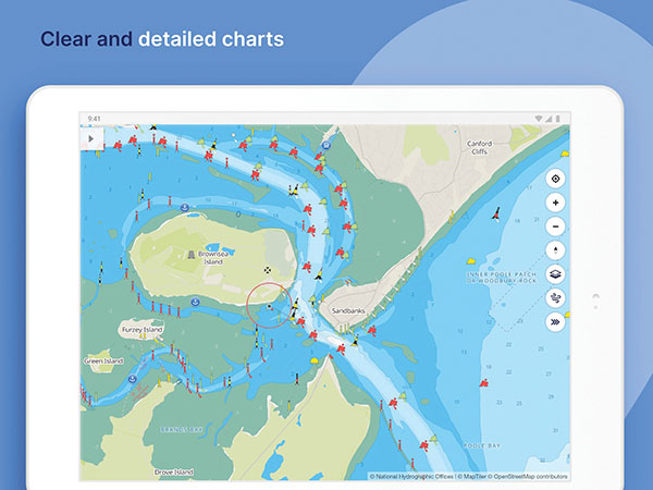
New departure scheduling charts route, wind, tides
Photo: Savvy Navvy
Smartphone app Savvy Navvy now allows boaters to plan better by visually showing the best time to depart given wind and tidal implications, leading to more informed and cost-saving decisions for journeys. By comparing passage times, as well as weather and tide information, boaters can immediately make crucial decisions based on safety, comfort, time and cost. Savvy Navvy is available on Android, iOS, PC and Mac and can be used on an unlimited number of devices simultaneously. It charts, weather, tide, marina details and passage planning with full tidal vectors. Active GPS tracking shows vessel position and enables boaters to instantly check course over ground (COG) and speed over ground (SOG). The app uses UKHO, NOAA and other official hydrographic charts from around the globe, as well as tide data from 8,000 tidal stations.
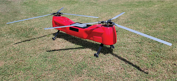
The Anzen EG-1250 provides a heavy lift, multi-drop, long endurance and flexible platform, expanding the services and operational support offerings from UAS Global Services. With an endurance of six hours, the EG-1250 can carry 75 pounds, cruise at 65 knots, in any weather day or night. The EG stands for an electric and gas dual-engine configuration, with the secondary engine able to power the aircraft or act as a power boost for the primary Skypower rotary SP-180 SRE engine. The Anzen EG-1250 is auto-rotation capable and offers an optional safety parachute system. The flexible platform can support industries such as maritime, agriculture, oil and gas, utility, cargo delivery and intelligence, surveillance and reconnaissance (ISR).
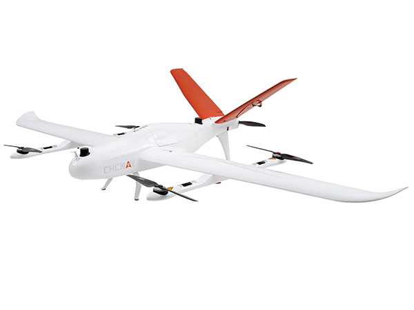
The P330 Pro is a high-performance vertical takeoff and landing (VTOL) fixed-wing UAS for aerial surveying and mapping. It provides high accuracy, long endurance and multiple payloads. It features a 100-Hz differential module, which allows aerial mapping operations at the centimeter level, and a flight endurance with payload reaching more than 150 minutes. The P330 Pro can be used to conduct small- and large-scale aerial surveys with extreme data quality, and is an alternative to manned aircraft for surveying and mapping, mining, construction and infrastructure, environmental monitoring and agriculture.
Capability expansion enables M300 for data capture
Photo: Skycatch
Flight1x software now provides data-capture capabilities for the DJI Matrice 300. The Skycatch High Precision Package provides mining operations with cloud or edge-based data processing that enables viewing terrain in 4D, automated RTK/PPK industrial drone management, and fast edge processing with data visibility in minutes. Built on technology adopted by large mining companies, Flight1x includes purpose-built flight automation software for the M300, leveraging DJI’s L1 and P1 sensors. Flight1x is part of the Skycatch High Precision Package, which provides mining operations with cloud or edge-based data processing that enables viewing terrain in 4D, automated RTK/PPK industrial drone management, and fast edge processing with data visibility in minutes.
Offers 5G and artificial intelligence capabilities
Photo: Qualcomm
The Flight RB5 5G platform is designed to accelerate development of commercial, enterprise and industrial drones. Powered by the Qualcomm QRB5165 processor, it condenses multiple complex technologies into a tightly integrated drone system. With 5G and Wi-Fi 6 connectivity, the platform enhances critical flying abilities beyond visual line-of-sight to support safer, more reliable flight. High-performance computing provides power efficiency for artificial intelligence and machine learning, enabling fully autonomous drones. A secure processing unit supports cybersecurity protections. New camera capabilities deliver premium image capabilities and performance. The Flight RB5 5G drone reference design is available through ModalAI. Use cases include mapping, inspection, film and entertainment, defense, security and emergency response, and delivery.
Spirent GNSS Foresight lets operators know where and when unmanned vehicles, air taxis and drones can operate safely and dependably beyond visual line of sight, especially in urban areas where buildings frequently obstruct GNSS signals. The cloud-based solution can produce forecasts using data from any of the world’s satellite constellations, and is of particular interest to the aviation, UAS and automotive industries. Spirent GNSS Foresight’s ability to accurately predict where and when autonomous systems will perform enables users to scale operations or services by expanding operational areas, reducing the number of system disengagements, and providing a greater level of safety and reliability assurance when reducing — or ultimately removing — human involvement in the driving or piloting task.
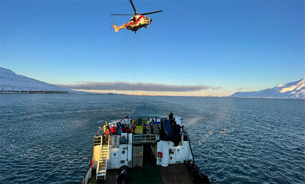
The AMRO 2021 exercise tested the rescue of 200 cruise-ship passengers using Galileo SAR. (Photo: EUSPA)
News from the European Union Agency for the Space Programme (EUSPA)
In freezing arctic waters 60 nautical miles off of Svalbard, a search-and-rescue enactment proved the capabilities of Galileo as a life-saving system.
The Arctic Mass Rescue Operation (AMRO 2021) took place on Oct. 8, organized by the Norwegian authorities. The scenario surrounded a cruise ship that caught on fire with around 200 passengers onboard, located northwest of Spitsbergen far from roads, cabins, rescue crews and other infrastructure.
The vessel’s crew activated a Galileo-enabled EPIRB compatible with Galileo’s Return Link Service. Once activated, it took only 2:20 minutes for the Galileo System to track down the ship with an accuracy below one kilometer and deliver an SOS acknowledgement to the active EPIRB.
Once the Mission Control Centers received the distress signal and established the location, two Super Puma helicopters from the Governor of Svalbard, a Sea King from the 330 squadron of the Royal Norwegian Air Force, and a Norwegian coast guard support vessel were scrambled to support the massive evacuation of the passengers.
‘’The AMRO 2021 exercise was an excellent opportunity for the European Union Agency for the Space Programme to showcase the power of Galileo SAR and the robust performance of Galileo at high latitudes in comparison to other GNSS constellations,’’ said Guerric Pont, Head of Galileo Department at EUSPA.
The Galileo RLS allows people in distress to receive an automatic acknowledgment that their signal has been picked up by the first responders. Galileo’s contribution to the Medium Earth Orbit Satellites Search and Rescue System (MEOSAR) — managed by the international COSPAS-SARSAT program — translates into 2,000 lives saved per year.
In support of Galileo’s SAR operations, the Copernicus Marine Service provides authorities and rescue centers input such as wave height, sea current direction as well as and water temperature among others.
A link to the live event will be sent to you two hours before the event. Your personalized event URL will be automatically generated by the ON24 system. To ensure receipt of the email, please whitelist this email address by adding it to your contacts: [email protected].
This presentation will begin at 11 a.m. EDT / 8 a.m. PDT on Thursday, October 28. A recording will also be sent to you the following day so you can watch it on-demand.
Audience members may arrive 15 minutes prior to live time. If you have any questions, please contact event producer Mackenzie Shoemaker at [email protected].