Teledyne Optech has added to its line of airborne laser terrain mappers with the ALTM Galaxy T1000. The new system combines a 1000-kHz effective ground measurement rate with Optech’s SwathTRAK technology to create a compact, efficient and versatile lidar sensor.
The Optech Galaxy T1000 reduces operating costs and improves performance. Photo: Optech
Core to the Galaxy T1000’s enhanced collection efficiency is a doubling of the laser pulse repetition frequency and a further increase to its variable-terrain capability with SwathTRAK technology, which reduces the number of flightlines by up to 70 percent over traditional fixed-FOV sensors.
SwathTRAK leverages the Galaxy’s programmable scanner by dynamically adjusting the scan field of view (FOV) in real time during data acquisition, enabling constant-width data swaths and constant point density even in highly variable terrain.
The result is far fewer flightlines to collect and process and a consistent point distribution, whether on hill peaks or valley bottoms. The steeper the terrain, the greater the cost savings, according to Teledyne Optech.
The Galaxy T1000 also includes PulseTRAK technology, which enables a continuous operating envelope. This lets surveyors employ very high laser pulse repetition frequencies to generate high point-density data at high altitude and in variable terrain without the need for complex flight planning. Full 100 percent point density is maintained across the multi-pulse transition zones for true data integrity without data interpolation.
“Cost reduction is the key driver for leadership in competitiveness in today’s geospatial data acquisition market,” says Michael Sitar, airborne business manager for Teledyne Optech. “The new Galaxy T1000 offers unparalleled collection cost savings, particularly in variable terrain, while maintaining all the advantages of independent range measurement and the highest data precision and accuracy from high altitude achievable today. We are excited to offer the most advanced survey instrument at a far superior price/performance ratio and in the most compact package for utmost installation flexibility.”
OCO-3 will collect spaced-based measurements of atmospheric carbon dioxide and solar-induced fluorescence.
Once launched, OCO-3 will be installed and operated on the International Space Station (ISS) Japanese Experiment Module-Exposed Facility (JEM-EF).
Surrey’s SGR-20 is a single-frequency, multiple antenna GPS receiver designed as a spacecraft orbit determination subsystem for small satellite low-Earth orbit applications. The OCO-3 mission will use the Surrey SGR-20 for positioning information (to an accuracy of better than 20 meters) and velocity data (to an accuracy of better than 0.25 meters per second). The SGR-20 features four front ends with antennas, allowing more flexibility and redundancy for the selected mission.
According to Eugene Hockenberry, project manager at Surrey Satellite, “The SGR-20 receiver is part of a highly proven range of GPS receivers that Surrey Satellite offers. Our receivers are currently active on twenty-four Surrey satellites and have accumulated over 700 years of on-orbit experience. With this mission we will see another first for Surrey: this receiver will be our first space hardware onboard the ISS.”
Surrey Satellite delivered the receiver to JPL three months ahead of schedule. OCO-3 is scheduled to launch in 2018.
GeoMax has updated the firmware on its Zenith35 Pro GNSS receiver, which was introduced in November 2016.
The update is for NovAtel’s OEM7 Measurement Engine built into the receivers. Update OM7MR0102SN0005 addresses a real-time kinematic (RTK)-network connection issue preventing reception of corrections when connecting to selected NTRIP networks in some countries.
Note that the receiver’s onboard firmware version remains unchanged at 2.01.
The compact and fully ruggedized Zenith35 Pro has 555 channels. Its multi-constellation and multi-frequency capability supports all satellite systems today and in the future.
The Zenith35 Pro incorporates “Tilt&Go” functionality that allows users to measure inaccessible points. This significantly increases efficiency in the field, since leveling time is eliminated. Tilt and compass values for each measurement are stored for quality control and documentation purposes.
The unit is IP68-rated for water and dust, and is shock protected.
The Oregon Department of Transportation (ODOT) is embracing the growing trend in highway construction to go “stakeless” and push to full 3D design.
With more contractors using automated machine guidance applications, ODOT’s construction personnel are being asked to inspect projects with fewer stakes and visual indicators for line and grade. Employees are seeking to use the same data and information to determine line and grade when building or fixing stretches of road.
ODOT inspectors Jorge Jimenez and Mike Stennett at Multnomah Falls, preparing for a night-time paving operation. (Photo: Chris Pucci)
To address this need, rugged tablet maker DT Research worked closely with ODOT to design purpose-built Inspector Positioning Tablets that run GPS locating and 3D modeling applications, and take advantage of the Oregon Real-Time GNSS Network.
“MicroSurvey Field Genius surveying software is used to read XML files directly, allowing the inspector to work with the same files that the contractors received from the roadway designers,” said Chris Pucci, ODOT Construction Automation Surveyor.
The tablets enable ODOT to fully use its knowledge of the Oregon Real-Time GNSS Network and expertise in survey-grade RTK GNSS to achieve accuracies of +/0.05 feet.
The model DT391GS tablets have 9-inch touchscreens. The tablets can be used as handhelds or with an external antenna and pole. ODOT purchased one of four GNSS options offered by DT Research for the DT391GS tablets. The options enable inspectors and construction crews to employ a combination of GPS locating and 3D modeling to guide construction workers.
The goal is to allow the inspectors to make the same checks they would have made if there had been traditional construction staking on a project, not to make inspectors into surveyors, Pucci noted.
A one-day training is provided to train construction personnel before they are issued a tablet. “The tablets have been very well received by our construction inspection personnel,” he said.
The tablet project is now in the pilot phase with 20 tablets deployed to eight construction offices and more than 70 construction personnel having been trained. “We also just placed an order for 22 more tablets for the upcoming 2017 construction season,” Pucci said.
A region in France is working with SNCF (the French National Railway Company) to foster the emergence of new solutions — including GNSS technologies — for the operation and control of regional trains and railway infrastructure.
On Sept. 1, the Occitanie/Pyrénées-Méditerranée Region and GUIDE (GNSS Testing Laboratory) signed an agreement to open a railway line to field tests for companies seeking to perform assessments aboard trains. The agreement is supported by the French space agency CNES and the Aerospace Valley Center.
The Geofer project, managed by GUIDE, will allow the testing of applications in operational situations. The applications are based on radionavigation and telecommunication data initially intended for other business sectors.
Through the Geofer project, the Occitanie/Pyrénées-Méditerranée Region is pursuing two strategic goals. The first aims to strengthen mobility within the region through better control of operating costs. The second is to diversify industrial activities with rail. The project could lead to modernization of secondary lines of the national railway network by embedding, for example, some functions of railway signaling.
The test region — the Tessonnières-Rodez line (Tarn/Aveyron) — crosses a mountainous area conducive to tests in constrained environments.
As leader of the project, GUIDE is working to geo-reference the line and to instrument a train that will calibrate future embedded applications. The collected data will then be re-used and replayed on test benches to help solution developers tune their embedded systems more easily.
A co-financer of Geofer, CNES is actively involved in the tests. A receiver implementing an algorithm (PPP-WIZARD) developed by its engineers will be tested on board, using software to exploit future satellite services to achieve decimetric accuracy. This technology could make possible many rail applications such as precise dock stops or a better prediction of maintenance operations.
M3 Systems will supply the mission receiver responsible for dispatching accurate and real-time data about the positioning and speed of the train to embedded applications. This device merges the satellite measurements with those of other sensors used to ensure the quality of the geolocation messages.
For example, devices such as shock sensors to detect unusual efforts of the pantograph against the overhead cable, speed control systems for eco-driving, and roaming systems for telecommunication will be developed, implemented and evaluated on the line and on simulation benches.
Handheld Group, a manufacturer of rugged mobile computers and tablets, has launched the Algiz 8X ultra-rugged tablet computer. The Algiz 8X is built for field workers who require a powerful, portable computer for mobile tasks.
The Algiz 8X offers GPS and GLONASS positioning via u-blox, along with an 8-inch projective capacitive touchscreen that is ultra-bright and built for outdoor use. Enabling glove mode or rain mode allows for operation in changing weather. The chemically strengthened glass survives an impact test in which a 64-gram steel ball is dropped on the screen 10 times from a height of 1.2 meters. The Algiz 8X also comes with an optional active capacitive stylus.
“The new Algiz 8X is the most compact and ergonomic Windows tablet we have ever developed,” said Johan Hed, director of product management.”We’ve pushed the limits of modern field technology with this product, fulfilling customers’ needs for powerful computing, mobility, outstanding screen performance and battery life. We made no compromises.”
Built-in features
The Algiz 8X rugged Windows tablet by Handheld Group. Photo: Handheld Group
The Algiz 8X comes standard with Windows 10 Enterprise LTSB to meet the needs of enterprise customers who value long-term stability. Other features include:
u-blox GPS and GLONASS
WLAN a/b/g/n/ac
BT 4.2 LE
A rear-facing 8 MP camera with autofocus and LED flash
4G/LTE
Expansion options
The Algiz 8X offers LAN port, COM port or barcode scanner options. It also features a “backpack” system that allows users to add custom features and electronics.
Ruggedness
The Algiz 8X is rigorously tested for use in tough outdoor and industrial environments. It’s IP65-rated for dust and water ingression and meets stringent MIL-STD-810G military standards for:
Operating temperature: -20°C to 60°C (-4°F to 140°F) — Method 501.5, Procedure II
Storage temperature: -40°C to 70°C (-40°F to 158°F) — Method 501.5/502.5, Procedure I
Drops: 26 drops from 1.22 meters (4 feet) — Method 516.6, Procedure IV
Vibration: Method 514.6, Procedures I & II
Humidity: 0-95% (non-condensing) — Method 507.5
Altitude: 4,572 meters (15,000 feet) — Method 500.5, Procedure I
Orders can be placed immediately. Units will be in stock in March 2017.
The untethered 3D dead-reckoning GNSS module NEO-M8U by u-blox is at the core of Navilock’s new GNSS receiver series for service vehicles. The new portfolio will enable retrofitting of dead-reckoning and untethered dead-reckoning (UDR) technology in any vehicle.
Photo: Navilock
Combining multi-GNSS (GPS, GLONASS, BeiDou, Galileo) with an onboard 3D gyro/accelerometer, the untethered dead-reckoning technology improves position accuracy even where GNSS signals are weak or unavailable, such as in urban canyons, tunnels or parking garages. Receivers with a serial MD6 interface can work in an extended voltage range from 5-48 Volt DC.
Applications for Navilock’s new GNSS receiver series include service vehicles from the police, fire departments, emergency physicians, disaster rescue teams and technical aid organizations that require accurate positioning at all times. Operational forces and their control centers must be constantly aware of their location to enable successful completion of any assignment. As a result, physical dangers and even life threats are clearly minimized.
“We have been collaborating for years with u-blox and highly respect the quality and reliability of its products,” says Karsten Reschke, Navilock product manager. “Particularly critical for our product range is the UDR technology that enables reliable and accurate location capability even without satellite navigation signals.”
“We are pleased to be associated with the Navilock brand and the quality and design reliability it represents,” says Andrew Miles, u-blox product manager. “The ease of use and robust packaging of these products perfectly enable the value of UDR in its target applications.”
Launched in 2016, the u-blox NEO-M8U enables reliable positioning even in case of GNSS signal interruptions, jamming, reflected or weak signals, and is independent of any connection to the car, other than power.
The eight new Navilock GNSS receivers will be available in Q1 2017.
Fieldbook F60 from Logic Instrument. Photo: Fieldbook
The new Fieldbook F60 from Logic Instrument is a smartphone designed to optimize the workflow in industrial environments. Logic Instrument is a French manufacturer of professional mobility solutions.
The Fieldbook F60 combines the convenience of a large 6-inch touchscreen, the functionalities of a smartphone and a professional barcode scanner in one device.
Compared to traditional mobile terminals with built-in barcode scanners, the F60 displays 12 times more pixels (720×1280 vs. 240×320), allowing for easier data input and more reading comfort.
The F60 features a built-in Honeywell 1D/2D barcode scanner that scans barcodes quickly adn precisely and with a low failure rate.
The Fieldbook F60 integrates the technologies required to optimize tasks in vertical markets:
4G LTE mobile broadband, NFC, GPS, Wi-Fi, BT BLE
Docking station and user replaceable battery
Drop resistant to 1.2m
High temperature range from -20°C to +60°C
Resistant to the intrusion of liquids and dust (IP67)
Topcon Positioning Group has released a new modular GNSS receiver system, the MR-2. The system combines all current and planned constellation tracking with a comprehensive set of communication interfaces to service any precision application requiring high-performance real-time kinematic (RTK) positioning and heading determination.
Topcon MR-2 GNSS receiver. Photo: Topcon
The MR-2 can perform as a mobile RTK base station, marine navigation receiver, mobile mapping device and as a GNSS receiver for agricultural, industrial, military or construction applications.
“The MR-2 delivers navigation support for a wide-range of applications,” says Jason Hallett, vice president of Topcon global product management. “It is an ideal component for OEMs (original equipment manufacturers) needing a custom, high-accuracy modular design for easy integration.”
“The MR-2 is also designed as a ‘future-proof’ system,” Hallett says, “meaning it tracks all current and planned constellations, making it a smart investment in the expanding GNSS environment.”
The unit housing is water and dust-proof and built to withstand harsh environments with superior vibration and shock tolerances, he adds.
Using Topcon HD2 heading determination technology, the MR-2’s dual antennas compute high-performance heading and inclination determination alongside the RTK positioning engine for precise navigation and guidance applications.
“The MR-2 also provides a variety of communication interfaces such as Ethernet, serial, and CAN, allowing for easy integration into any application,” Hallett says.
The system also offers best-in-class multipath rejection, and using Topcon Quartz Lock Loop technology can operate without disturbances in high-vibration environments.
I have mixed emotions as I write this column. Delighted, absolutely, to be given the opportunity to write for GPS World on topics that I am so passionate about; but also sad that we will not see any more articles from Don Jewell, whose excellent columns I followed so religiously over the years. I never had the opportunity to meet Don personally but, to me, he is irreplaceable. But let’s talk about the changing face of defense positioning, navigation and timing (PNT) — not in the editorial sense, but in the technology sense.
As we all know, PNT and GPS are no longer synonymous. With a host of innovative technologies on the horizon, PNT is about so much more than GPS these days, and the military knows it. Sure, GPS has been the workhorse of PNT for many years, and it’s not going anywhere anytime soon. I’ll be clear on that: GPS is not going anywhere. But it’s not a complete solution either.
Let me paraphrase what a friend in the infantry tells me, by saying GPS is a 60 percent solution to their navigation needs. What does that mean? Well, it goes something like this:
60 percent of the time: GPS is great, it does what we need.
20 percent of the time: We are indoors or underground, and GPS is simply not available.
15 percent of the time: We’re in an urban canyon. GPS availability is intermittent, and the accuracy is poor.
4 percent of the time: We’re in forests or dense vegetation, and GPS is sporadic.
1 percent of the time: GPS is jammed.
You can argue the numbers depending on the mission, but you get the idea. What, then, is the answer for the soldier? Well, first things first: We don’t want to reinvent the good 60 percent so, once again, GPS is here to stay. The question is how do we push past that 60 percent figure and get ourselves closer to 100 percent? Let’s go from the bottom up, and address GPS jamming.
Overcoming interference
The classic solution to jamming is an adaptive antenna, also known as a controlled radiation pattern antenna (CRPA). More on this another time but, for now, suffice it to say that CRPAs are a well-understood and mature technology, and can offer very high levels of jamming resistance.
The often-cited disadvantage of a CRPA antenna is its size, weight and power: As CRPAs employ multiple antenna elements, they are inherently larger and heavier. The electronics can pretty much be covered by a single chip these days, leaving the antennas themselves as the problematic aspect, but advances in antenna technology have also made big hurdles.
For airborne platforms, conformal antennas designed as part of the structure or fuselage can be used; whilst for the dismounted soldier, the trend is towards wearables, where the antennas may be an inherent part of the clothing or helmet design.
Aside from adaptive antennas there are a whole host of other techniques in your anti-jam kit bag, including receiver-based techniques.
It’s a numbers game
For forests and urban canyons, this is where multi-frequency multi-GNSS comes into its own. It really is a numbers game: The more constellations you use, the more satellites you can choose from, and the greater your chances of seeing enough satellites to derive a reasonable navigation solution. You also have more options for mitigating the effects of multipath and other errors.
Of course, this gives rise to a potentially difficult question for some governments: In defense applications, do you want to rely on foreign GNSS constellations as part of your PNT solution? The attitude here depends on your own country’s policy and a trade-off of perceived gains against perceived threats. The UK, for example, has chosen to embrace all available constellations and frequencies in future military navigation systems.
That’s probably about as far as GNSS gets you, because now we’re looking at the 20 percent of the time where the user is indoors or underground. In other words, environments where GNSS simply isn’t available. This 20 percent is perhaps more tricky to address, and is the realm of alternative and complementary PNT technologies.
Beyond GNSS
Fusing different sensor modalities to create a combined navigation solution is anything but a new idea. The benefits of combining GPS with an inertial sensor were recognized a long time ago, and this classic pairing continues to be the subject of research today.
The two technologies are highly complementary in various ways: GNSS offers absolute position, low short-term accuracy, and high long-term accuracy. On the other hand, an inertial sensor offers the opposite: relative position, high short-term accuracy, and low long-term accuracy. It’s a match made in heaven.
But whilst GNSS plus inertial may be a good choice for, say, airborne platforms, it doesn’t solve the in-building and underground problem. Without GNSS, you need something else.
Indoor navigation has been one of the hottest research topics of recent times, but there are really two types of indoor scenario: the first is when you’re in a shopping mall or airport. You can use an inertial sensor, Wi-Fi, mobile base stations, and various other bits of infrastructure to help you navigate.
The second scenario is the military one: You’re in an unfamiliar enemy compound or underground tunnel complex. In this case, there is no GNSS, no Wi-Fi, no mobile communications; and, for navigation, you can only really rely on the sensors you bring with you.
So what other sensor works underground, and complements inertial?
Visual/inertial integration
Visual odometry is an established, yet often overlooked, navigation technology that is undergoing a resurgence of interest, in both military and civilian applications. In simple terms, visual odometry uses sequential camera images to determine motion in a six degrees of freedom reference frame. Using either single or multiple cameras a platform can estimate both its 3D position and orientation, providing much the same information as an inertial sensor — but with a few added benefits.
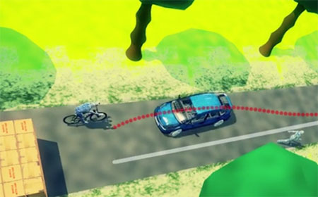
Visual/inertial sensing allows 3D reconstruction of a road incident. (Screenshot: Roke)
Because cameras and associated vision-processing algorithms are capable of detecting corners and features, a 3D model of the environment in which the soldier is operating can also be built up. In other words, we can perform simultaneous localization and mapping (SLAM).
But like any navigation technology, visual odometry has its limitations. It likes well-defined features in the environment, such as corners, but can get confused by moving objects like trees and clouds. Its performance also depends on factors such as the quality of the camera and lens, and how well the system is calibrated. Like an inertial sensor, it provides a relative positioning solution and is subject to accumulation of errors over time. It’s a great technique, but it really comes into its own when combined with another navigation sensor, such as an inertial unit.
And it’s not just the military guys who are taking advantage of visual/inertial integration. Just take a look at Google’s Tango project, or what Qualcomm is doing, or Roke’s black box for driverless cars, to name but a few examples.
Bringing it all together
Over the course of the last decade or two, the operational landscape for soldiers has changed significantly, with far greater focus on urban warfare. The military realized some years ago that the answer to robust navigation for dismounted soldiers was going to require a range of sensor modalities: no single navigation technology is ideal in all environments. That’s why this has been the focus of so many defense programs of recent years.
By way of example, the UK Ministry of Defence (MoD) initiated a research program in 2013 called Dismounted Close Combat Sensors (DCCS). The contract addressed a range of soldier capabilities, one of which was the ability to provide reliable soldier position and orientation in all environments.
The DCCS programme evaluated a whole bunch of technologies, but eventually converged to an integration of three primary sensors: multi-constellation GNSS, a low-cost inertial measurement unit (IMU) and a video camera. The single monocular video camera was used to strap down the IMU, in a very tightly-coupled system. It makes sense: when GNSS is available, use it. When GNSS isn’t available, the integrated visual/inertial navigation sensor continues to provide both location and orientation for the duration of the mission. As it should be for a tightly integrated navigation system, the performance of the combined system outperforms any individual sensor in isolation.
Whilst integrated sensor systems enable our soldiers to position, orientate and navigate themselves, the performance of individual sensors continues to be pushed to new limits. Inertial technology is advancing all the time, and defense is again pushing the boundaries. Take a look at what DARPA is up to, as an example.
The missing ‘T’
Haven’t we missed something? Ah yes, there’s a “T” in PNT. So whilst there would seem to be various options for achieving a robust positioning and navigation solution, we mustn’t forget precise timing for those applications that need it. Quantum technology is flavor of the month here and, once more, the defense agencies are furthering developments: DARPA with its ACES program, and MOD/DSTL via the Quantum Technology Program, to illustrate just a couple of examples.
So whilst GPS will continue to remain the workhorse, defense PNT is migrating from GPS-only to being a many-faced beast. And I haven’t even gotten started on pseudolites, signals of opportunity, eLoran, and cooperative navigation.
The future of defense PNT looks pretty good to me.
Spirent Communications plc will demonstrate its expanded focus on security at the cybersecurity RSA Conference 2017, held in the Moscone Center in San Francisco Feb. 13–17. In a classroom session, Spirent positioning security technologist Guy Buesnel will discuss deliberate threats to GNSS.
Focusing on deliberate attacks against GNSS at the application layer and through RF channels, Buesnel will introduce session attendees to the vulnerabilities of satellite navigation and timing systems and how they have been exploited. Based on his experience in protecting GNSS receivers from emerging threats for nearly two decades, Buesnel’s session will address the evolution of deliberate GNSS threats and present the latest evidence of deliberate jammer use from a network of detector devices.
“There are compelling parallels between the manner in which IP threats have developed on the internet and the evolution of both jamming and spoofing attacks against GNSS,” said Buesnel. “Once people understand that the evolution of GNSS threats not only has clear parallels with the way in which IP threats have evolved, but also that GNSS share many of the features of a connected network, they will see that many of the lessons learned by the information security community apply equally well to the GNSS community.”
Part of the Mobile & IoT Security track, the Guy Buesnel classroom session (Session Code MBS-F01) will take place 9–9:45 a.m. on Friday, Feb. 17, on the second floor of the Moscone West hall, room 2002.
Spirent will also preview new Cyberflood performance and security validation software at RSA.
“With our expanded focus on security, Spirent is addressing the growing need in government, industry, health care and financial services for effective products and services to assess, validate and monitor the performance and security of their networks and applications,” said John Weinschenk, general manager of applications and security at Spirent. “We look forward to demonstrating at the RSA Conference how our industry-leading product and service offerings can meet today’s need for performance and security effectiveness under a wide range of real-world threat and attack scenarios.”
Spirent representatives in the company’s booth (S2015 in the Moscone South hall) will be available during the show to speak with attendees about the Cyberflood software and many of its upcoming ease-of-use features and real-world threat and attack emulation capabilities. The new features will include a flexible advanced testing component for customized testing needs and extended fuzzing techniques that enable users to find more issues faster and understand them better than any competing product in the industry.
Attendees will also be able to learn more about the scanning, penetration testing, monitoring and source-code-analysis security services available from Spirent Security Labs for networks, wireless infrastructures, websites, mobile applications and embedded devices.
A controlled radiation-pattern antenna can preserve GNSS positioning while providing at least an azimuth angle towards an interference source. If integrated with an attitude and heading reference system (AHRS), only a few lines of position pointing towards the RFI source could provide a fast indication of the probable ground location.
By Gerhard E. Berz, Pascal Barret, Brent Disselkoen, Michael Richard, Vincent Rocchia, Florence Jacolot, Todd Bigham and Okko F. Bleeker
GNSS is an essential enabler for many aviation applications that rely on either accurate position or time synchronization. While the idea of “sole means” GNSS is disappearing, it remains challenging to match the performance and coverage of GNSS with terrestrial systems. This is why aviation is working on Alternate Positioning, Navigation and Time (A-PNT) to cope with the potential for a wide-area GNSS outage. Current navigation aids are clearly part of this approach in the short term. We will continue to need a terrestrial capability for some time, but we don’t expect that it will support the same level of performance as GNSS. Even if we have back-up, we must be able to resolve GNSS outages efficiently.
Among principal GNSS vulnerabilities — constellation performance issues, space/solar weather and radio-frequency interference (RFI) — RFI is the one where observability on the ground is often limited. While the protection of radio services from interference is a state responsibility typically assigned to a telecommunications or other government agency, it is in the interest of an air navigation service provider (ANSP) to be able to request help and enforcement action from the telecommunications regulator in an efficient manner.
As a part of its contribution to Single European Sky ATM Research (SESAR, a collaborative project to improve European airspace and its air traffic management), Eurocontrol has developed an RFI Mitigation Plan as a guidance framework with the objective to maintain risks to GNSS and the associated operations at tolerable levels. The document will be published by ICAO in its GNSS Manual in the new 2017 edition.
MITIGATION PLAN
RFI can be a security issue. Consequently, a commonly used philosophy in the security domain was used in the mitigation plan: there are many potential threats, but not necessarily all of them translate into operationally relevant risks. Threats are thus sort of dormant risks, which, if left to develop unmitigated, could develop into risks to aviation. The mitigation process monitors threats, assesses risks, and then implements suitable mitigation to stop threats from developing into risks. Three successive stages have been identified where such barriers can be applied:
Prevent transmission of RFI, mostly through radio regulatory actions and coordination;
Prevent interruption of positioning and navigation capabilities in the presence of RFI. This is achieved at the avionics level by making sure receivers can tolerate some RFI as well as redundant capabilities;
If interruption cannot be avoided, ensure that other communication, navigation and surveillance capabilities provide continued safety while being able to detect, locate and eliminate an RFI source efficiently.
This third barrier is where flight inspection or other aerial work platforms can play a significant role. However, this role is not limited to risk mitigation. Aerial measurement capabilities can also play a role in threat monitoring by getting data on RFI emissions that are too weak to pose operational risks, and facilitate risk assessment by providing a reliable reference of the impact of such signals on an aircraft in flight.
FLIGHT INSPECTION
Similar to the subject of flight validation, airborne GNSS signal-in-space testing must not necessarily rely on traditional flight inspection capabilities. Other aerial work capabilities can be used, and it is hoped that, over time, data from regular aircraft operations and event recording systems can be used at least for threat-monitoring purposes. However, as soon as a significant RFI occurs, purpose-built aerial detection and localization capabilities are hard to beat. Given that aviation is carrying the risks related to RFI, and telecom regulators are unlikely to have such capabilities, this naturally points to the experience and resources of flight inspection aircraft and their crews.
Even if a significant amount of ground-based RFI sensors are available, local building shadowing can make it difficult to impossible to detect and locate an RFI emitter. Aircraft-provided data can be superior to ground data, and a rough aircraft-based localization can greatly increase efficiency of ground-based localization and source elimination efforts. Aerial RFI localization capabilities offer unique strengths in an overall cooperative process.
EVOLVING SIGNALS
GNSS manifests the transition from analog signals of conventional navigation aids to digital ones. A common characteristic of digital signals is their better use of a frequency channel by spreading the carrier energy such that distinct carrier or subcarrier tones become difficult to observe. Unfortunately, RFI sources have kept up with this, and now most commonly employ swept CW signals, easy to produce but still looking essentially like broadband signals. Many unintentional RFI sources also look like broadband.
Because GNSS is a multi-modal system not uniquely used by aviation, a new type of RFI threat is becoming more common: intentional RFI, which is not directed at aviation, but may nonetheless have an impact. Because there is no direct intent to harm aviation, the nature of these signals and RFI scenarios can become diverse and unpredictable. Furthermore, given the prevalent and ubiquitous nature of GNSS, the number of potential RFI threats is more significant and will evolve more dynamically than aviation capabilities.
A recent effort collecting GPS outage data reported by pilots revealed that a small but surprising number of outages that could potentially be linked to RFI occur on a regular basis, even during en-route operations in some limited regions of the world. For flight inspection, this implies it would be useful to increase the sensitivity of RFI source detection commensurate with the digital nature of GNSS and consistent with the power levels that can impact receivers.
Another particular challenge comes from the specification of an interference mask for GNSS. Other navigation systems do not have such a mask, or any kind of minimum signal-to-noise ratio standard. The mask represents a realistically achievable interference environment. It has been adopted as a global benchmark where receivers experiencing signals above the mask may not produce misleading information, but may stop operating.
However, in practice, little is known about by how much typical receivers exceed the minimum masks. Some tests have reported a margin as significant as 23 dB to CW and 10 dB to broadband signals. This means that an RFI which may not bother one type of receiver at all could be a significant problem for another, limiting the possibility to rely on observed receiver performance. It also implies that signal-in-space effects should be detectable at the low levels of the ICAO receiver RFI mask.
CRPA LOCALIZATION
For civil aviation as opposed to military operations, a CRPA could make sense provided that it outperforms current RFI localization methods at a reasonable price. In military applications, the exact location of the RFI source may be of a secondary nature, as long as desired signal tracking can be maintained.
However, by steering a null (negative gain) towards the angle of arrival of an undesired signal source, a line or sector of possible source positions can be obtained. In this case, the main objective would not be to null a deliberate interferer or jammer, but to obtain a bearing on the type of the interferer. The main scenario we worry about that leads to low-power events are those where aviation is not the desired target, such as a PPD. Unintentional cases can be a mix of high- or low-power cases. The use of a GNSS-specific antenna is expected to provide the required sensitivity, while being able to profit from the military off-the-shelf development. When further integrated with standard flight-inspection sensors such as an attitude and heading reference system (AHRS) and additional geolocation software, this approach has the potential to increase the reliability, accuracy and speed of geolocation while reducing operator effort and flying time. An additional potential benefit is the preservation of ownship position when flying into an area of significant RFI.
The suggested use of military technology brings with it the question on how such use could be authorized. CRPA antennas and associated antenna electronics manufactured in the United States fall under the International Traffic in Arms Regulation (ITAR). While this is a solvable but, nonetheless, cumbersome issue, the approach taken by this project was first to evaluate possible benefits from using a CRPA before worrying about the ITAR issue.
This study was conducted by Eurocontrol in the frame of a SESAR Project on GNSS, including a contract with Rockwell Collins for a feasibility study of the CRPA RFI localization concept. The French (DSNA/DTI) and U.S. FAA Flight Inspection service supported the project with expertise and in-kind contributions. The FAA conducted an overflight with a direction-finding-equipped aircraft for direct comparison between the CRPA approach and other, non-GNSS specific, commercial solutions.
TECHNOLOGY OPTIONS
Current, common GNSS CRPAs come in either 4- or 7-element variants. CRPAs always require antenna electronics for further processing of the RF inputs, and perform either nulling (steering negative gain towards RFI sources) or beamforming (steering positive gain towards GNSS satellites), or both. The most performant system is a 7-element CRPA in combination with digital beam-former antenna electronics. The 7-element CRPA has a diameter of 36 cm (14 inches), which is of some concern for installation on a typical flight-inspection aircraft such as the Beech King Air. But for a feasibility study, it makes sense to first evaluate the most-performing option. If there is unnecessary margin, the solution can be simplified afterwards.
A top-mounted solution on the airplane fuselage was retained due to experience with military anti-jam performance suggesting that RFI localization performance would be sufficient while retaining the benefit of stable ownship position. A key element of the assessment focused on how to best use aircraft banking to facilitate geo-localization.
As shown in Figure 1, the CRPA is connected to the Digital Integrated GPS Anti-Jam Receiver (DIGAR). As there is one RF cable per CRPA element, it is useful to install the DIGAR as close as possible to the CRPA. The standard military-production DIGAR contains not only the antenna electronics but also the receiver including baseband processing. For civil purposes, either a civil receiver would need to be integrated into the DIGAR or, alternatively, a single RF output is available to connect a standard civil GPS receiver. The DIGAR will also feed angle-of-arrival information into a direction-finder software.
Figure 1. System configuration. Source By Gerhard E. Berz, Pascal Barret, Brent Disselkoen, Michael Richard, Vincent Rocchia, Florence Jacolot, Todd Bigham and Okko F. Bleeker
The software provides angle-of-arrival information with respect to the antenna/aircraft reference frame. To provide a geolocation capability, this must be combined with ownship position and aircraft attitude. As most flight inspection aircraft are equipped with an AHRS, this is not expected to be a problem. Project resources did not permit full integration, so testing was done using the direction-finder display only. The AHRS would need to provide 10–50 Hz updates with an error of not more than ±2 degrees.
Figure 2 shows an example of the direction-finder output. Lighter areas show where the antenna electronics produce negative gain, while darker areas represent stronger positive gain. The red dot indicates a potential interferer has been identified. Source location is at about 280 degrees of azimuth with respect to aircraft nose.
Figure 2. Excerpt from direction finder polar display of RFI signal angle of arrival. Source By Gerhard E. Berz, Pascal Barret, Brent Disselkoen, Michael Richard, Vincent Rocchia, Florence Jacolot, Todd Bigham and Okko F. Bleeker
Correct detection probability will depend on the sensitivity threshold and associated false detection probability being considered acceptable. A visual localization may still be possible at carrier-to-noise density ratios (C/N0) below those needed to produce the red dot here, especially if the visible ambiguity can be removed through some aircraft maneuvering. It can be inferred from the system description that once the full integration is accomplished, the provision of a direct output using only a few lines of position to find a probable RFI source location in terms of approximate lat/long coordinates should be straightforward.
SIMULATOR TESTING
A well-calibrated simulator capable of feeding the seven RF inputs was used to assess detection performance for different flight patterns near an RFI source. The tested patterns include a rectangular, a circular and an oscillating, S-shaped trigger-and-hunt trajectory. A variety of different encounter scenarios in terms of power levels and free space path loss were tested. Power levels were adjusted to produce a 1-dB reduction in the C/N0. Both a continuous wave (CW) interferer at the L1 center frequency and a broadband (BB) interferer were simulated (using a 20-MHz-wide PSK signal). Figure 3 shows an example of achieved detection accuracies in both azimuth and elevation angle.
Figure 3. Example result of angular detection performance. Source By Gerhard E. Berz, Pascal Barret, Brent Disselkoen, Michael Richard, Vincent Rocchia, Florence Jacolot, Todd Bigham and Okko F. Bleeker
While there is a strong peak within ±10 degrees of azimuth, there are also significant outliers. For the elevation (note the normalized scale), however, the main peak is thinner with even stronger sidelobes. Due to the installation of the antenna on top of the aircraft fuselage, the simulation results indicate that the elevation angle output is not very useful for detection. The time series result for the azimuth is given in Figure 4, where it can be seen that there are many good detection matches but also some “sympathetic nulls” that move in the opposite direction of the ground track truth reference (circled in grey). It is expected that with additional software processing, these sympathetic nulls can be filtered out.
Figure 4. Azimuth Time Series Result Corresponding to Figure 3. Source By Gerhard E. Berz, Pascal Barret, Brent Disselkoen, Michael Richard, Vincent Rocchia, Florence Jacolot, Todd Bigham and Okko F. Bleeker
For all tested scenarios (assuming additional filtering), azimuth detection capability was better than ±10 degrees (one standard deviation), and in some cases as accurate as ±2 degrees. There was no significant difference between CW and BB results. As could be expected, simulated aircraft banking significantly improved detection capability. Consequently, the use of orbits seems to be the best search strategy. The simulator testing used a figure-eight pattern with one of the orbits passing over the interference source.
LIVE-SKY VAN TESTING
Rockwell Collins has an authorization to broadcast RFI test signals at the GNSS L2 frequency. Previous work showed that the results at L2 can be applied equally to L1. Figure 5 shows the test area, including a –100-dBm signal level boundary. The interferer was installed on a tripod and fed by a signal generator using a normal GPS fixed radiation pattern antenna (FRPA).
Figure 5. Live-sky test area. Source By Gerhard E. Berz, Pascal Barret, Brent Disselkoen, Michael Richard, Vincent Rocchia, Florence Jacolot, Todd Bigham and Okko F. Bleeker
Locations B and C were used to both calibrate the RFI level and as check points for the van trajectory. The test van included a fixture that allowed a tilting of the CRPA by 30 degrees from zenith to either side. Figure 6 shows a schematic of the tilt fixture. It can be seen that this set up creates a realistic RFI path that arrives with an elevation slightly below the horizon at the unit under test. Two sets of tests were performed: one where the van drove straight into or out of the area of interference to determine overall equipment sensitivity, and varied paths to quantify angular detection performance. Again, both CW and BB RFI signals were evaluated.
Figure 6. CRPA with tilt fixture. Source By Gerhard E. Berz, Pascal Barret, Brent Disselkoen, Michael Richard, Vincent Rocchia, Florence Jacolot, Todd Bigham and Okko F. Bleeker
Not surprisingly, elevation angle results turned out not to be very reliable given the below horizon signal path. But azimuth errors were slightly greater than obtained during the wavefront simulator testing (±12 degrees, one sigma). This can be attributed to both multipath and a less accurate heading truth reference. Taking these additional factors into account, the results are very consistent. Tilting the antenna by 30 degrees towards the RFI source significantly improves azimuth resolution (to about ±8 degrees) while also reducing sympathetic nulls. When the tilted antenna points away from the RFI source path, azimuth accuracy will decrease, which is considered helpful in avoiding false detections.
Summary. Even if a good bit of integration work remains necessary to produce a production-ready system for flight inspection or other similar aircraft, the approach shows promise. Further testing, especially using an actual aircraft installation, is recommended. Installation of a 7-element CRPA will be challenging on a typical Beech King Air, but possible. Antenna calibration requirements are expected to be manageable with a standard network analyzer. To avoid further complications with export regulations, the use of a separate civil GNSS receiver is recommended. The overall system is, at this stage, still on the costly side.
While a 4-element CRPA could be used, this was estimated to double or triple angular azimuth detection errors and reduce the detection distance, and consequently not likely to be worth the additional cost. While smaller 7-element CRPAs than the one used are available, their performance would need to be assessed.
For a top-mounted CRPA, aircraft banking is essential to ensure good performance. This could increase the amount of airspace required for detection and lead to operational complications. Furthermore, since the aim is to increase detection sensitivity to geo-locate weak power sources such as personal privacy devices, maintaining ownship position is not that critical, as it can be managed by maintaining an appropriate distance from the RFI source if needed. Consequently, both DSNA and FAA recommend using a bottom-mounted CRPA. In addition to adding 10 dB of detection sensitivity on average and reducing the need for maneuvering, it may restore the utility of the elevation output, thereby potentially further reducing search time. Either way, it will be useful for equipped aircraft to have alternate positioning capabilities to GNSS both for aircraft guidance and truth reference systems.
The system required a 15-dB stronger signal to transition from detection to localization. However, this is dependent on the accepted false-alarm rate. A tunable procedure can be envisaged where the software accepts a higher false-alarm rate at first to maximize search capability and moving to a lower alarm rate to confirm suspected RFI source locations later. Both the potential of the additional filtering software and any human-machine interface aspects would need to be further evaluated.
GENERIC CAPABILITIES
The two common options for in-flight detection of RFI sources in any relevant frequency band are the use of either a spectrum analyzer or, if available, a direction finder. The spectrum analyzer approach depends on connection to a suitable antenna, preferably with some directionality. In this way, the aircraft can be maneuvered to point the antenna either towards or away from the RFI source. Normally there is very little directivity, making this a challenging search. A direction finder is a significant improvement. Figure 7 shows the L-band antenna array used by a DF-4400 as installed on the bottom of the aircraft.
Figure 7. CRPA with tilt fixture. Source By Gerhard E. Berz, Pascal Barret, Brent Disselkoen, Michael Richard, Vincent Rocchia, Florence Jacolot, Todd Bigham and Okko F. Bleeker
Newer generation spectrum analyzers with a good GNSS-specific pre-amplifier, using digital sampling with a fast A/D converter, could provide useful capability. However, the subject is beyond the scope of this discussion, and we focus here on comparing the CRPA approach with a standard direction finder.
The FAA Flight Inspection service conducted complementary flights during the Rockwell Collins live-sky van testing. The flights included orbits and a direct overflight of the RFI source. This was complemented by additional laboratory calibration to ensure that results could be compared. The sensitivity results of the CRPA approach are more meaningful in comparison with a generic direction-finder capability. Since test data is only available for a top-mounted CRPA, the comparisons here are made for the preferred bottom-mounted CRPA using engineering estimation.
The key finding was that while direction-finding capability was quite comparable between the CRPA- system and the DF-4400 for CW, the CRPA-system outperforms the DF-4400 by a significant margin when encountering broadband signals. This is considered to be a significant improvement given the expected nature of RFI sources. During the FAA overflight, the aircraft did not manage to detect the broadband signal. Consequently, the values given here are reconstructed from laboratory analysis. Table 1 compares the estimated achievable sensitivities.
Table 1. Comparison of direction-finding sensitivity. Source By Gerhard E. Berz, Pascal Barret, Brent Disselkoen, Michael Richard, Vincent Rocchia, Florence Jacolot, Todd Bigham and Okko F. Bleeker
In view of the limitations of the data analysis performed, these values must be interpreted with caution. In general, we can conclude that the direction-finding sensitivity of the CRPA system is relatively insensitive to the encountered modulation of the RFI signal, and that the bottom-mounted CRPA system outperforms the DF-4400 system by a small margin in the CW case and by a large margin in the broadband case. How many additional dBs can be gained by both approaches through further optimizations is for future analysis. The performance improvement of the CRPA system does come at a cost, as could be expected.
DETECTION
Before the search for an RFI source can begin, it must be detected. Normally it should be easier to detect an RFI source than to locate it, since direction-finding requires a certain signal strength to obtain bearing information. However, given the directionality of DF arrays, this may not necessarily be true. Another potential factor is the reliance on a spectrum analyzer to detect RFI, which may not achieve the corresponding noise floor, especially when using a broad scan across a wide frequency range. The direction-finder system needs about a 15-dB difference between detection and localization ability.
Figure 8 shows the detection ranges for the top-mounted CRPA system for a given ground-based emitter while the aircraft altitude is assumed at 2000-ft AGL. The bottom mounted system would improve the minimum detection threshold further. Given that 15 dB can translate into a significant difference in free space path loss distance, concepts for efficient direction finding once an RFI source is detected deserve further attention.
Figure 8. Detection ranges for top-mounted CRPA system. Source By Gerhard E. Berz, Pascal Barret, Brent Disselkoen, Michael Richard, Vincent Rocchia, Florence Jacolot, Todd Bigham and Okko F. Bleeker
HUMAN FACTORS
During the FAA overflight, the broadband RFI couldn’t be detected by either the spectrum analyzer in use or the DF-4400. Part of the challenge was using the right equipment settings. For the DF-4400, it was found that best performance could be obtained for detecting broadband RFI when using the FM wide mode of demodulation. Similar findings were obtained for the use of the spectrum analyzer, where specific skills are necessary to use the equipment to its fullest capability. Similar issues are expected when having to interpret the display of a CRPA-based system. This means that regardless of the RFI source geo-location approach used, specific training should ensure that aircraft operators have the greatest chance of success in finding RFI sources.
CONCLUSIONS
An approach using a CRPA antenna, electronics and processing software proved superior to current, generic direction-finding capabilities, especially with respect to broadband signals. Maintaining ownship position in the presence of RFI is a secondary objective when looking for the expected weak signal sources, and the use of a bottom-mounted CRPA system is preferred. Additional filtering to eliminate sympathetic nulls and other issues require further investigation.
Significant benefit derives from employing aerial work aircraft in cooperation with ground-based capabilities. We recommend that equipment manufacturers further study all aspects of GNSS RFI geo-location and improve their capabilities. Such capabilities are expected to limit the exposure time to RFI cases and allow a more efficient deployment of ground-based spectrum enforcement resources. These studies should include the improvement of detection and localization equipment, and the development of corresponding operational procedures for flight crews.
ACKNOWLEDGMENTS
The Eurocontrol-funded contract with Rockwell Collins is part of the Eurocontrol contribution to SESAR Project 15.3.4, GNSS Baseline and the GNSS RFI Vulnerability Mitigation Task.
Rockwell Collins provided the DIGAR and Direction Finder Software.
This article is based on a paper presented at ION-GNSS+ 2016.
Disclaimer. This article does not contain any official Eurocontrol, SESAR, FAA or DSNA position or policy. It does not constitute any endorsement of a particular product, or a statement of any kind relating to any future procurement activity.
GERHARD BERZ and PASCAL BARRET work at Eurocontrol, Belgium; VINCENT ROCCHIA and FLORENCE JACOLOT with Direction des Services de la Navigation Aerienne, France; BRENT DISSELKOEN and MICHAEL RICHARD at Rockwell Colins, U.S; Okko F. Bleeker with OFBConsult System Engineering, the Netherlands; and TODD BINGHAM with the U.S. Federal Aviation Administration.