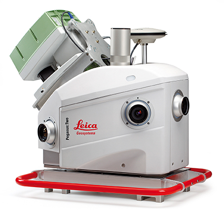
Leica Geosystems has introduced its next generation vehicle-independent mobile mapping platform, the Pegasus:Two. By calibrating imagery and LiDAR point cloud data, the Pegasus:Two delivers highly accurate and economical geospatial data in a 360° spherical view while providing two methods for extracting data — either through LiDAR or via photogrammetry.
With its enhanced sensor platform using six horizontal cameras, plus an optional rear camera and a skyward view camera, a single high-speed LiDAR sensor, and an external output for an additional sensor, the Pegasus:Two enables unlimited mobile mapping applications, from pavement analysis to geo-referencing railways systems, now possible within the same platform, the company said.
From hardware to post-processing, Pegasus:Two allows economic data collection by balancing the largest pixel to sensor ratio on the market (5.5 x 5.5 µm), delivering extremely high image resolution, in a 4-MB camera and using a single low-noise, high-speed profiler. Users can download data via Wi-Fi or wired Ethernet, or even faster by using the latest USB3 interface, by means of a multi-core, industrial PC with 1-TB storage and a solid state drive, enabling longer missions. An optional rotation mount, designed specifically for the Leica ScanStation P20, also makes mounting the terrestrial scanner upside down or right side up while also enabling left or right rotation.
The Pegasus:Two in its new streamlined housing with aerodynamic design.
Expanding on the success of Leica Geosystems’ mobile mapping software, the latest software now offers semi-automatic object extraction features, which enable easy-to-use two-click GIS metadata extraction or calculation of distances on-the-fly directly into ArcGIS for Desktop software.
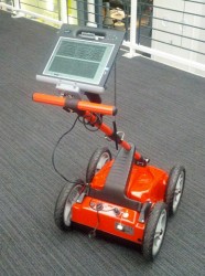
Leica Geosystems also introduces an external timing output and trigger signal for use with a variety of additional sensors, from a thermal camera, to ground penetrating radar, sonar, or even a pollution monitor. The External Trigger feature synchronizes time stamping and coordinates user data with one simple click, making 3D mobile mapping very user-friendly.
Urban canyons. Equipped with the NovAtel’s ProPak6 high-precision receiver for the most demanding city or rugged environments, the Pegasus:Two offers users a truly global system. It is a future-proof investment that tracks signals of all available constellations, GPS, GLONASS, Galileo and BeiDou as well as L-band, SBAS, and QZSS band coverage to ensure the best signal even when moving through urban canyons. The system provides a low noise, 200hz Inertial Measurement Unit for tracking the vehicle path thereby ensuring data is positioned accurately.
Aerodynamic design. The Leica Pegasus:Two mobile mapping system now comes with a new streamlined and compact look and continues to fit in only two travel cases. A convenient handle surrounding the unit enables easy mounting on and off your vehicles. The Pegasus:Two is a vehicle-independent system with a rechargeable 11 hour battery, and can be used on any moving platform.
“The Leica Pegasus:Two platform is a unique complete solution,” said Stuart Woods, vice president for Leica Geosystems Geospatial Division. “By providing software and hardware designed to seamlessly work together, users not only receive the latest in mobile mapping technology but also optimal performance and faster workflows. By keeping the platform vehicle independent and adding new sensor options, we encourage our customers to find new ways, to try out different sensors, new revenue models, and new places to measure. ”
Along with the Pegasus:Two, the advanced prototype, Pegasus:T2, a trolley based mobile system weighing less than 20 kilograms will also be on display at the HxGN LIVE 2014 Conference in Las Vegas.
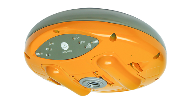
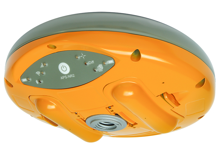
Altus Positioning Systems has introduced its new APS-NR2 RTK surveying receiver. The new product is being previewed at the 2014 Geo Business conference and exhibition in London May 28-29, and will be commercially available in July.
“The APS-NR2 provides a powerful combination of high GNSS RTK performance, light weight, low power consumption, versatile Quad-band modem, remote Web-based access and connectivity with Esri’s cloud-based platform,” said Neil Vancans, Altus president and CEO. “The result is a versatile product designed to enhance productivity and minimize downtime in the field for a wide range of surveying and geolocation jobs.”
The APS-NR2 is Altus’ second-generation RTK rover, building on the highly successful APS-3 product series. It features an easily accessible on-board web interface and integrated Wi-Fi for easy remote configuration and status monitoring, as well as Bluetooth for real-time data streaming, providing true cable-free operation. In parallel to RTK positioning, data can be recorded on a removable 2-GB SD memory card for post-processing.
The APS-NR2 is built around a low-power 132-channel GPS/GLONASS L1/L2/L2C SBAS receiver, which offers robust RTK performance, as well as DGPS capability. The internal 3.5G Quad-band GSM/GPRS/EDGE cellular modem supports RTK network connectivity. Dual internal cellular antennae ensure a positive signal lock and minimize disruptions due to dropped calls.
The new Altus receiver comes with two Li-Ion batteries. It has a built-in USB battery charger, as well as a separate two-bay external charger. The batteries are hot-swappable, allowing uninterrupted productivity on the job.
With Altus’ open-architecture philosophy, the user has a choice of data collector software from Carlson SurvCE, MicroSurvey FIELDGenius or direct interface to Esri ArcGIS Online, as well as proprietary customer-developed software.
The APS-NR2 doesn’t sacrifice essential processing power or connectivity and still weighs only 0.7 kg (1.5 lbs). The compact receiver is just 69 mm (2.7 in) high and 167 mm (6.6 in) in diameter. The rugged unit is waterproof to IP67 and has an operating temperature range of -40 to +85°C.
GPS World Publisher Steve Copley is attending GEO Business 2014, where GPS World is a sponsor. The show is being held in London this week. He’s been tweeting from the show. Follow his tweets here, and GPS World’s Twitter account here.
GEO Business 2014 is a new geospatial event for everyone involved in the gathering storing, processing and delivering of geospatial information. It is organized in collaboration with The Chartered Institution of Civil Engineering Surveyors (ICES), The Association for Geographic Information (AGI), The Royal Institution of Chartered Surveyors (RICS) and The Survey Association (TSA).
There has been a lot of GNSS-related news in the past month, so I thought I’d do a quick review of the importance (and possibly unimportance), of news you may have heard about.
Just because some GPS satellites weren’t broadcasting CNAV on L2C and L5 doesn’t mean your receiver isn’t using L2C or L5. On the contrary, if your receiver was designed to handle L2C and L5, it’s likely already been using them. The CNAV is just the message being transmitted on the L2C and L5 carrier along with the code. If your receiver tracks L2C and L5, it’s likely already using the carrier (phase) observations. However, even then there are only a limited number of satellites broadcasting L2C and L5 carriers. Specifically, there are 11 satellites broadcasting L2C and four broadcasting L5, meaning that your receiver is roughly tracking one L5 satellite at any one time during the day and several satellites broadcasting L2C.
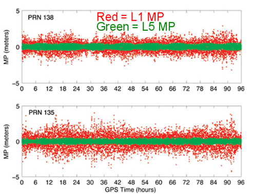
The C/A code (NAV) message on L1 that your receiver already uses today is good enough. Your receiver doesn’t need the CNAV message on L2C or L5 to utilize the L2C or L5 carrier observations. That’s not to say there’s no benefit to CNAV on L2C and L5, but for RTK or post-processing, the value is largely in the carrier observations. In the future, when L2C and L5 are fully deployed (or near fully deployed), the L5 CNAV does have some distinct advantages, but that’s a few years down the road. To give you an idea of the benefit of L5 when there are enough GPS satellites broadcasting L5 , take a look at the following illustration published by Dr. Richard Langley from the University of New Brunswick comparing the reduction of code multipath on L1 and L5 of two WAAS GEO satellites.
Reduction of code multipath using L1 and L5 on WAAS GEO Richard B. Langley, Hyunho Rho
For the full text of the Langley/Rho article on L5 and WAAS that appeared in the May 2009 issue of GPS World magazine, click here.
Second GPS IIF Satellite of 2014 Launched May 16
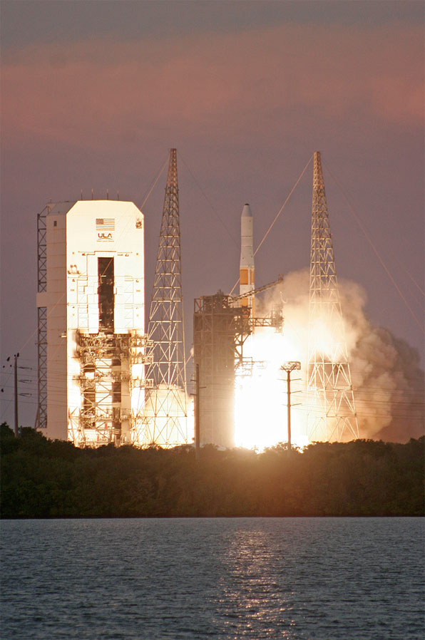
On May 16, the second GPS satellite of 2014 was launched successfully from Cape Canaveral in Florida. It was the sixth model IIF GPS satellite, of which 12 are being built, before transitioning to the next-generation model GPS satellite named GPS III. It began transmitting on May 21, 2014, but is not yet set healthy.
Photo credit: Spaceflight Now.
The GPS model IIF satellite broadcasts the legacy GPS signals as well as the new civilian L2C and L5 signals.
Normally, a launched GPS satellite is set healthy (and automatically begin being used by your GPS receiver) within 30 days of launch, sometimes much sooner. However, the IIF GPS satellite launched in February of this year still hasn’t been set healthy, the reason reportedly being an extended navigation test reported here.
A third GPS IIF satellite is scheduled for launch this year on July 31.
During the post-launch interview last Friday, the Air Force stated that the remaining GPS IIF satellites (six) will be launched by the end of 2016. From previous conversations I’ve had with Air Force officials, they’ve stated that there could be an overlap between IIF and III satellite launches. In other words, the first GPS III satellite could be launched before all IIFs have been launched.
“Since March 15, 2014, the Air Force has been conducting functional checkout on a GPS satellite, designated Space Vehicle Number (SVN) 64. SVN-64 broadcasts a data message that clearly indicates SVN-64 is unusable for navigation. Nevertheless, the U.S. government has confirmed that certain GPS receivers are using data from SVN-64, in violation of GPS interface specifications, resulting in outages or corrupted, inaccurate position calculations.”
CGSIC reports that the GPS continues to operate and is fully functional.
In Australia, faulty GPS receivers on roughly 1,000 fleet vehicles caused an apparent GPS “outage” about a month ago.
The U.S. Air Force GPS Operations Center reported that in mid-May tests, “PRN 30 [was] broadcasting almanac datasets that do not reflect constellation changes that occurred since it was last uploaded with navigation message data. [. . . ] The utilization of these almanacs in a manner that regards the time of week, but neglects or mishandles the week number (effectively executing as if the current week number is the week number associated with these almanac parameters), will result in an increasing error in visibility determination and other almanac based estimations (elevation/azimuth, Doppler shift, SV clock offset from GPS time, etc) as the dataset’s actual week offset from the current week increases.”
First Two FOC Galileo Satellites Arrive in French Guiana for Launch Preparation
The first two Fully Operational Capability (FOC) Galileo satellites arrived in the French Guiana in preparation for launch this summer. When launched into orbit, they will join four IOV (In-Orbit Validation) Galileo satellites launched in 2011 and 2012.
The first FOC satellite launch may signal the beginning of Galileo “production” launches of one pair per quarter. Giuliano Gatti, Head of ESA’s Galileo Space Segment Procurement Office, stated that “A steady stream of satellites is foreseen, coming from OHB to ESTEC for acceptance testing and then on to French Guiana. Thanks to the preparatory work done with these pioneer satellites, future Galileos will be processed more rapidly.”
OHB is the prime contractor for a total of 22 FOC Galileo satellites. Those are in addition to the four IOV Galileo satellites.
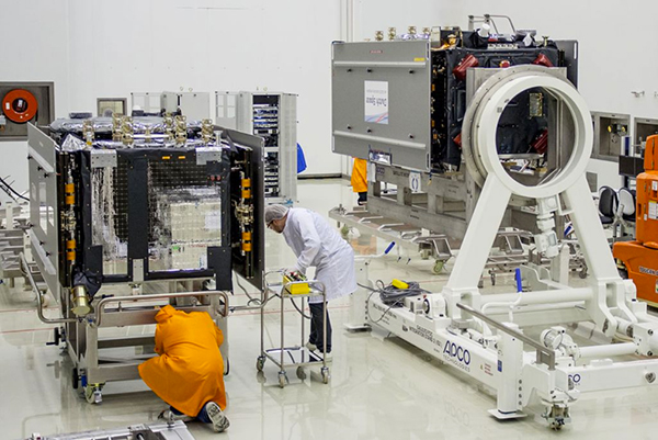
The two Galileo satellites in the clean room.
Massive GLONASS System Failure
On April 1, the entire GLONASS system was inoperable for about 11 hours. A second, partial failure involving eight GLONASS satellites occurred on April 14 and lasted for about 30 minutes. There were many reports of RTK receivers not operating properly, and some manufacturers instructed their users to “turn off” GLONASS tracking capability on their receivers.
Subsequently, mathematical mistakes were blamed for the failures. The head of the Russian Space Agency, Oleg Ostapenko, stated that the problem would be fully resolved by mid-May and that there is almost no chance of a similar failure happening again.
Some news media are reporting that such an action by Russia would have an effect on GPS.
It would not.
What they’re talking about is discontinuing operations of some or all IGS (International GNSS Service) GPS stations in Russia. Those stations have nothing to do with the operation of GPS. They are simply CORS (Continually Operating Reference Stations). If anything, it will hurt Russian scientists (and scientists from other countries) more than anyone else.
Russian Rocket Launch Failure
Last week, Russia suffered its fifth rocket launch crash in the past four years. Fortunately for the GNSS user community, the rocket was not carrying any GLONASS satellites.
However, it raises serious concerns about the reliability of Russian rockets and launch procedures. Europe’s Galileo satellites are launched using Russian Soyuz rockets at Europe’s space port in French Guiana.
Trimble is offering Field Link 2.20, the latest version of its software for management of layout tasks associated with building construction. The new release extends field layout capabilities for contractors and field teams, providing task-based workflows, customizable views, and a touch-screen user interface designed to optimize the information presented.
To find the exact location of a point in the field, users can now visualize where they are inside the 3D model relative to the layout point in their Trimble Field Link software, giving a more intuitive, realistic 3D perspective viewpoint and making it easier to navigate to the selected point.
Trimble Field Link Version 2.20 encompasses updates to Trimble Field Link for MEP and Trimble Field Link for Structures field software, which now include augmented 3D model support, and an enhanced in-model perspective layout view for a more productive and realistic field layout experience. Trimble Field Link also provides users with better visualization, navigation and rendering of building models, as well as the capability to import much larger, more sophisticated models.
In addition to the advancements made in performing layout-specific tasks, Trimble Field Link adds reporting routines to detail layout productivity, and the ability to document existing site conditions for information requests (RFIs).
Bentley Systems. Trimble also announced its collaboration with Bentley Systems to enhance information mobility between the design and field construction processes. This collaboration enables users to share their 3D constructible models between design and engineering applications and Trimble Field Link 2.20 via Bentley’s mobile i-model technology. A Bentley CONNECTIONS Passport, which entitles use of Bentley’s mobile apps and mobile i-models, is provided with Trimble Field Link.
Bentley i-models are containers for the open exchange of infrastructure information that enable project team members to share and interact with complex project data and across product lines and technology platforms. Using i-models, project teams can exchange and distribute packages of information within multi-organizational, multi-disciplinary, and multi-phase construction projects to continue uninterrupted workflows, and to easily adapt to real-time project changes.
“By joining forces with Bentley, Trimble is giving contractors and other building construction professionals greater choice, accuracy and flexibility in performing their field layout tasks,” said Mark Sawyer, general manager of the General Contractor / Construction Manager Division of Trimble Buildings Group. “Our companies share complementary visions of boosting productivity in all facets of construction projects, and we’re pleased to connect our advanced technologies to deliver greater benefits to the industry.”
Flawed processing of GPS satellite data in some GPS receiver chipsets has caused concern, but the problem is not with the GPS constellation itself. “SVN 64 broadcasts a data message that clearly indicates SVN 64 is unusable for navigation. Nevertheless, the U.S. government has confirmed that certain GPS receivers are using data from SVN 64, in violation of GPS interface specifications, resulting in outages or corrupted, inaccurate position calculations,” Executive Secretariat Rick Hamilton, Civil GPS Service Interface Committee (CGSIC), said in a May 15 message.
Read the full text of the message below.
Known Problem with Certain GPS Devices
May 15, 2014
Recently, many GPS users have reported intermittent GPS outages in their devices. After investigating, the U.S. government has linked the problem to flawed processing of GPS satellite data within certain GPS receiver chipsets. The GPS satellite service continues to function as designed and is fully operational and available worldwide.
The problem affects only user equipment that erroneously ignores the satellite health status information broadcast from every GPS satellite. The problem is not related to the April 28, 2014, activation of civil navigation messages on the GPS L2C and L5 signals.
Since March 15, 2014, the Air Force has been conducting functional checkout on a GPS satellite, designated Space Vehicle Number (SVN) 64. SVN 64 broadcasts a data message that clearly indicates SVN 64 is unusable for navigation. Nevertheless, the U.S. government has confirmed that certain GPS receivers are using data from SVN 64, in violation of GPS interface specifications, resulting in outages or corrupted, inaccurate position calculations.
The Air Force testing is scheduled to end in mid-May 2014 at which time SVN 64 will begin normal operation. At that point, these problems may stop occurring. Meanwhile, the U.S. government urges all GPS device makers to review their products for compliance with the GPS interface specifications, and if necessary, to issue software/firmware updates to users as soon as possible. View specifications.
Users experiencing GPS outages should check with their device manufacturers for available software/firmware updates. In addition, any civil user seeing unusual behavior in GPS user equipment should report it to the U.S. Coast Guard Navigation Center (NAVCEN). Aviation users should file reports consistent with FAA-approved procedures. Military users seeing unusual behavior should report it the GPS Operations Center (GPSOC).
Please direct any civil user questions to NAVCEN at (703) 313-5900,
http://www.navcen.uscg.gov
Please direct any military user questions to the GPSOC at (719)
567-2541, DSN: 560-2541, [email protected] https://gps.afspc.af.mil
Military alternate: Joint Space Operations Center, (805) 606-3514,
DSN: 276-3514, [email protected]
Applanix Corp. and American Aerospace Advisors, Inc. (AAAI), have agreed on an OEM supply agreement that will incorporate Applanix direct georeferencing technology into AAAI’s unmanned aerial platforms. The collaboration creates a commercially available professional-grade mapping UAV system for civilian applications such as pipeline monitoring, power line surveys and emergency-response mapping.
The availability of the system follows a series of successful test flights of AAAI’s RS-16 Unmanned Aircraft System equipped with Applanix’ DMS-UAV aerial photogrammetry payload with commercially available inertial technology. Joint teams from Applanix and AAAI planned and flew a sequence of missions to evaluate the capabilities, including the ability to provide highly accurate, directly georeferenced and orthorectified aerial imagery without the need for ground control points or aerial triangulation calculations.
The system — consisting of the airframe, its avionics, mobile ground control station, telemetry systems and the digital mapping payload — performed according to expectations and successfully produced high-quality imagery.
The announcement was made at AUVSI’s Unmanned Systems 2014 Conference in Orlando Florida, where the most comprehensive collection of unmanned systems for every domain – air, ground and marine – are on display. A video of the system can be watched here.
“The OEM supply agreement with Applanix formalizes our plans to transform the aerial mapping industry by creating an integrated, professional-grade mapping system for unmanned flight,” David Yoel, CEO of American Aerospace Advisors, said. “For civilian aerial survey projects, this can mean safer operations, lower costs and more efficient deployments while still delivering very high accuracy. We are very pleased to announce the availability of the RS-16 Direct Mapping Solution.”
“We believe this is a ground-breaking development for the airborne imaging systems market,” Joe Hutton, Director of Inertial Technology and Airborne Products at Applanix, said. “There has been a lot of attention on developing a commercial, directly georeferenced mapping solution for UAVs, and now it is a reality.”
The RS-16 with the Applanix DMS payload is available through American Aerospace Advisors directly, for sale to jurisdictions where it is permitted to fly civilian UAV systems.
The Leica iCON CC55 controller is part of the Leica iCON portfolio.
Leica Geosystems now offers the Leica iCON CC55 controller, a versatile and rugged PDA with a 3.5-inch color display, as part of its iCON construction portfolio. The handheld controls Leica iCON sensors, runs the iCONstruct field software, and has a QuadraClear sunlight readable display and a fast 1-GHz processor.
The smaller Leica iCON CC55 handheld controller, as well as the seven-inch Tablet PC Leica iCON CC65/66 field controller, are both fully integrated into Leica Geosystems’ iCON portfolio of hardware and software solutions. It runs the Leica iCON build or site software to display and connect measured points for as-built data capturing or to lay out points and construction lines directly from the digital construction plan. The controller provides flexible options for data communication and an extensive data storage.
The Leica iCON CC55 can be used to control the Leica iCON robot total stations, enabling one-person operation, saving time and increasing productivity for construction layout tasks and as-built checks, the company said. The optional Long-Range Bluetooth allows communication with the iCON robot 50 at distances of more than 350 m/1150 feet. Alternatively, the iCON CC55 can be used as a data logger with the Leica Builder manual total station. Together with the versatile Leica iCON gps 60 SmartAntenna, the iCON CC55 creates a compact and light-weight GPS rover system.
The iCON CC55 runs the state-of-the-art Windows Embedded Handheld 6.5 operating system and comes with 256MB NAND Flash memory and 8 GB of extended storage, enabling extensive data process and storage capacity. An internal WLAN module and Long-Range Bluetooth offer users impressive distance communication, the company said, and the longer life 5.6Ah battery lets users easily complete a full day’s work. The iCON CC55 also comes equipped with a 5-MP camera so users can document their construction projects.
Visual Intelligence has announced that its iOne Software Sensor Tool Kit Architecture (iOne STKA) is available for purchase or licensing by manufacturers of unmanned airborne vehicles (UAVs) who want to deliver an integrated UAV/geospatial imaging solution to customers.
Capturing high-resolution imagery for applications in engineering, construction, urban planning, military missions and other uses is a significant emerging market for UAV manufacturers, and Visual Intelligence’s iOne STKA makes it possible to bring high-resolution geospatial sensors to UAVs, the company said. By purchasing or licensing Visual Intelligence’s geospatial imaging platform, UAV companies can meet emerging demand for geoimaging solutions that combine the benefits of UAVs with the imaging capabilities of a geoimaging platform.
iOne STKA provides the technology foundation to configure a variety of multi-purpose sensors, including miniaturized 2D/3D applications, for the emerging UVS and mobile/handheld markets. The iOne STKA received the Geospatial Forum 2013 World Technology Innovation in Sensors Award, is the first to be considered for NEANY’s Arrow UAV, and is field-proven by the commercial large-format 2D/oblique/3D multipurpose metric mapping systems iOne IMS, iOne Stereo, and iOne n-Oblique.
With the iOne STKA, the same UAS/UAV sensor system architecture can be used for agricultural and forestry mapping, pipeline or corridor monitoring, utility assessments, aerial surveys, research, persistence surveillance and other metric 2D/3D professional applications. The iOne STKA is a modular multipurpose sensor platform reconfigurable for UAVs of any size. With the iOne STKA, UAV manufacturers are no longer limited to offer monolithic, single purpose DSLR type cameras. Using the iOne STKA technology, UAV end users can economically collect high-quality color or infrared NADIR, oblique, or video imagery as well as co-mount and co-register e.g., LiDAR and thermal sensors using the same system architecture.
“By providing UAV manufacturers and end-users with one reliable and performing end-to-end standard digital sensor system solution for MANY applications, we are empowering our customers with a more efficient and standard technology foundation and paradigm to grow their business, enhance their products, and maximize their return,” said Visual Intelligence President and CEO Dr. Armando Guevara.
At the core of the iOne STKA is Visual Intelligence’s Patented Advanced Retinal Camera Array (ARCA). Developed using open systems and object-oriented software engineering principles, the ARCA is “encapsulated” with a rich set of advanced proprietary software methods that integrate camera components. The ARCA enables the collection of different types of imagery, fused in one pass, producing low-cost, extremely accurate, high-resolution products. It also enables unprecedented array-based collection and functional scalability sensor fusion. The arrays made of these varied imaging devices perform like a single camera, producing one single metric, radiometrically and geometrically correct image, or set of co-registered and fused images; such as a Virtual Frame, of higher accuracy, resolution and quality than DSLR-based monolithic cameras.
Adds Guevara, “UAV manufacturers can take advantage and offer bundled with the iOne sensors Visual Intelligence’s advanced computing technology for fast cloud-based basic and advanced actionable information product generation. As a fully automated solution (from the sensor to the cloud), the iOne STKA includes processing software that uses streamlined workflows and processes imagery faster with multicore/multithreaded/GPU computing technology, making it easy to quickly produce and analyze products in a device-content eCosystem environment. This technology/business model is designed to provide UAV manufacturers and users recurrent ROI.”
UAVs built using sensors based on the iOne STKA have the following features and advantages:
Strong digital obsolescence resilience, extending the useable life of the system while improving operational efficiencies and reducing operating costs for an even better ROI.
In the field:
Collection scalability
Functional scalability
Sensor reconfiguration, e.g. increase collection or functionality as needed or per mission requirements.
Large cross-track and FOV collection through smaller aperture (ARCA enabled).
Ability to collect different sources of metric imagery that can be fused in one pass.
Sensor fusion: Ability to co-mount and co-register in a “small and tight packaging” the EO capability with any other EO or active sensor such as LiDAR, Thermal, IR, etc.
The iOne STKA software architecture is normative across all ARCA-based products; that is, the software is the same for different array configurations or sizes. This reusable component approach yields economies of scale in the manufacturing and use of multipurpose UAV/sensor configurations.
TerraStar is offering GNSS manufacturers revenue sharing opportunities, including the possibility to launch their own precise GNSS augmentation services via endorsed rebranding of TerraStar services as a reseller. According to TerraStar, this will provide an attractive recurring service revenue stream to GNSS manufacturers that was not previously available in the industry.
TerraStar is a brand name of TerraStar GNSS Ltd., which is a wholly owned subsidiary of Veripos Ltd. Following the acquisition of its parent company by Hexagon AB in March, it will continue as a neutral and independent provider of satellite delivered precise positioning augmentation services for land and nearshore markets. It is already well advanced in plans to expand its service offering, the company said.
Gary Wilcock, general manager of TerraStar, renewed the company’s commitment to resellers, integrators and end customers at the Munich Satellite Navigation Summit, held in March. “TerraStar will remain an open system available to all current and future partners,” Wilcock said. “The TerraStar service will remain available to all partners who have a valid contract on a perpetual basis for as long as long as the services continue to be delivered. We intend to be a long-term partner for our customers.”
Walter Steedman, CEO of Veripos Ltd. Added, “All partners will be treated on a level playing field. Strict information firewalls will be maintained for all TerraStar dealings with different business partners so that all can be assured that market or other sensitive information remains confidential.”
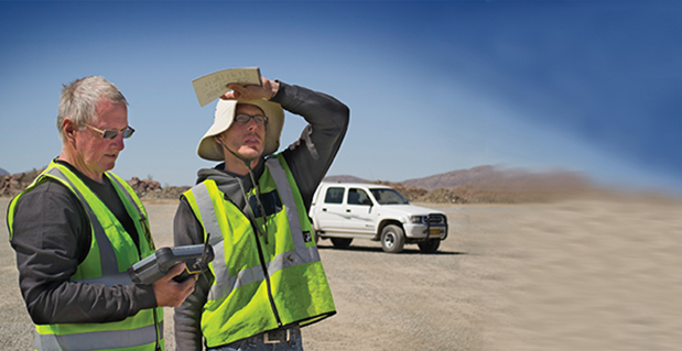
Dave and Arnold Bansemer prepare the X100 for the survey.
Surveying an open-pit mine can be a hazardous undertaking. To obtain accurate volume measurements, it is necessary to pick up edges, known in the industry as “toes and crests,” as well as heaps. These are important features, since they provide a way to verify the current shape of a mine; but in light of increasingly stringent safety regulations and penalties, some companies refuse to let the surveyor get too close to such areas. Surveying the site from the air is an effective solution to this challenge.
It’s also a cost-effective solution. Namibian Mining Survey Services (NMSS) estimates that using an unmanned aerial system (UAS) can save more than 95 percent in mobilization costs, that is, bringing in resources from outside the country to conduct a lidar/photogrammetric survey. Believing UAS to be an important part of the future of surveying, NMSS had been investigating the technology for some time, and a recent project provided the perfect opportunity to try it out.
NMSS selected the Gatewing X100 for the job based on a demo at a platinum mine, where the results closely tracked those of a previous lidar survey.
The Project
The project was to survey a portion of Abenab Mine, a vanadium-lead mine owned by South West Africa Company and located just west of Tsumeb. The mine had been closed in the 1960s, but feasibility studies were underway to see if it would be viable to reopen the operation. Mine management needed to know volumes of all waste and tailings dumps, slimes, dams, and open-pit excavations. The main pit was roughly circular, about 60 meters deep and 120 meters across. Two smaller pits were covered in fairly thick vegetation but had enough ground showing to provide an accurate shape.
The survey area was approximately 100 hectares. The flying height was set at 150 meters in order to provide a ground separation distance of 5 centimeters. Ground control points (GCPs) were constructed from 1-meter lengths of masonite cut into 10-centimeter-wide strips; painted bright red, the strips were designed to provide 20 x 2 pixel coverage on the images. A total of 10 GCPs were set out in strategic positions covering a wide range of elevations, with points on top of the dumps, on undisturbed ground level, and in the pits. The points were fixed from existing control on the UTM34S coordinate system, by fast static techniques.
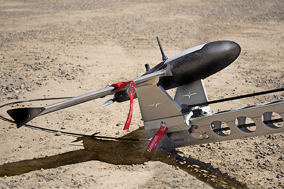
Launching the X100
The X100 prepares for flight.
Based on the Gatewing training received, basic photogrammetry principles and a few trials, NMSS determined that 9 a.m. to 3 p.m. was the best time to fly in order to avoid shadow. The flight area, including a previously surveyed area that would serve as a check, covered 140 hectares. Assuming favorable wind conditions, NMSS expected to cover the area on a single flight.
Arriving on site at 7 a.m., Dave Bansemer of NMSS started setting out the GCPs while his colleague performed the fast static survey. By 10 a.m., all GCPs had been placed and fixed. Having identified a suitable take-off and landing spot (a farm road), they proceeded through the pre-flight and flight checklist, and then launched the X100 at 11 a.m.. After completing the flight in around 35 minutes, with some turbulence at the 150-meter flying altitude, the X100 landed safely, albeit short of the goal, in an open area.
Once the data was downloaded, the team returned to Tsumeb to begin the processing. They started with the post-processing of the GCPs, and then moved to the coordinates obtained in the photo-control identification process. NMSS used Gatewing Stretchout Pro software for the photogrammetrical processing.
After specifying the coordinate system and identifying the GCPs, number-crunching began; the processing ran for around seven hours before the final point cloud and orthomosaics were created. The mean horizontal error was 3 centimeters and the vertical error was 9 centimeters, well within the error budget.
Results
Aerial image of the X100 survey.
The first check was to see if all areas had been covered. NMSS then checked the point cloud against the previous survey. The tie-in was perfect. Some gaps in the point cloud seemed to correspond with tree canopy areas; to ensure complete accuracy, the team resurveyed a few areas using a spatial station.
NMSS learned some important lessons from using UAV technology for survey, which Bansemer lists for the benefit of future users:
Make sure you have enough control. It is sometimes difficult to place your control points exactly in the corners of your flight and one in the center, as the actual flight is influenced by wind direction and the shape of the flight may change accordingly. Put down more points than recommended.
Make sure that your ground control point size is relevant to your flying height. You will not be able to identify a 10-centimeter wide strip if you fly at 300 meters.
Check the completeness of the job before you leave the area.
Make sure there is sufficient area for a safe landing. Bansemer recommends at least a 300-meter strip, taking obstacles into account in the event of a short landing.)
Manufacturers
The fast static techniques described were carried out with Trimble R6 GPS systems. Re-survey was done with the Trimble VX spatial station. The Gateway X100 is manufactured by Trimble.
Trimblehas released a new GNSS-based machine control solution to improve efficiency of bulk earthworks and landfill compaction operations. Installed on a four-drum soil or landfill compactor, the Trimble CCS900 Compaction Control System allows a machine operator to make more uniform and efficient passes, report compaction production data in the field, and ensure target compaction is reached with minimal fuel usage and machine wear.
The announcement was made at WasteExpo 2014, North America’s largest solid waste and recycling tradeshow.
CCS900 for Bulk Earthworks. The CCS900 system tracks compaction passes in real time with easy-to-read color mapping on the in-cab display. It improves bulk earthworks operations by ensuring fill material is adequately balanced and uniformly compacted from the bottom up.
CCS900 for Landfills. Landfill operations require contractors to compact the maximum amount of waste into the smallest area of vertical and horizontal cell space. Using CCS900, landfill owners can ensure that cell space is optimized, voids are eliminated and layers are compacted to their target density more efficiently. With real-time mapping on the in-cab display, the operator can avoid unnecessary passes that waste fuel and cause additional wear on the machine. The system also collects as-built layer information for in-field reporting and tracking of daily volumes.
In-Field Reporting and Printing for Quality Control. For both soil and landfill applications, Trimble CCS900 offers extensive in-field reporting options, including in-cab report generation and printing. This functionality allows compaction production analysis to be carried out in the field instead of waiting until data is transferred back to the office. Compaction progress and problem areas are indicated on the in-cab graphical control box and listed in the in-field report so they can be addressed immediately, instead of at project completion when re-work is more costly. An optional serial printer in the compactor cab also enables supervisors to sign off on the completion of the compaction work in the field.