Esri released Esri Maps for Office, a new analysis tool that allows business professionals to visualize data by creating and sharing interactive maps directly within Microsoft Office. Esri Maps for Office is a downloadable add-in for Microsoft Office 2010 that helps organizations make better decisions through location analytics.
"By bringing the power of location analytics to Microsoft Office, Esri Maps for Office extends mapping and geographic intelligence capabilities to new people and departments," said Jack Dangermond, Esri president. "Esri Maps for Office is the next necessary step to offering more robust business analytics throughout an organization."
With Esri Maps for Office, business professionals can quickly create interactive maps from their data in a Microsoft Excel spreadsheet. These live maps, which can be based on any geographic component, such as customer locations or sales by ZIP Code, can be simply added to Microsoft PowerPoint presentations or shared through Esri's cloud mapping platform, ArcGIS Online. Maps shared through ArcGIS Online can then be distributed throughout an organization or embedded into mobile or web applications.
The interactive maps and presentations business professionals create with Esri Maps for Office provide a powerful way of exploring issues ranging from gaps in existing service to opportunities for growth. Esri Maps for Office allows analysts to investigate their data as color-coded maps, point maps, or heat maps, and provides full control over the way data is displayed on the map. Organizations can overlay their data on a set of standardized Esri background maps or search through the extensive library of geospatial content available through ArcGIS Online.
Esri Maps for Office is available as a free download to organizations with ArcGIS Online subscriptions. For more information on Esri Maps for Office, visit esri.com/maps4office.
Esri announced a strategic alliance with Microsoft to assist public and private agencies and communities around the world during disasters. Microsoft will display Esri public information maps on its cloud-based Disaster Response Incident Portal, as well as point citizens to the maps via its online outlets, such as MSN and Bing. Esri's ArcGIS integration within a number of Microsoft's disaster response management solutions will provide governments and leading aid organizations with a more comprehensive set of tools to address key challenges.
Esri and Microsoft unveiled the alliance during the Esri International User Conference at the San Diego Convention Center in California.
"Esri is excited to work with Microsoft because of its world-leading software and services," says Russ Johnson, global director of disaster response for Esri. "This alliance leverages the strengths of both companies. The first phase involves using our technologies to support affected organizations and provide public information faster and in a more intuitive web map format during crises."
"The ability to include Esri intelligent, interactive web maps with Microsoft's suite of disaster response offerings increases our ability to assist government agencies and private citizens," says Harmony Mabrey, senior operations manager, Microsoft Disaster Response. "Both responders and citizens will have access to a more detailed level of knowledge about the impacts of a disaster, enabling them to make more informed decisions."
Accordinging to the announcement, these growing efforts will exponentially increase situational awareness and information sharing during disasters.
Benefits include the following:
Rapid data dissemination to targeted audiences and the general public during a disaster
Better situational awareness through Esri and Microsoft technologies for critical decision support
More information management resource availability for governments and leading response organizations through the combined efforts of Esri and Microsoft
GIS Cloud is pleased to announce the launch of its Enterprise Geo 2.0 Platform.
According to the announcement, the Enterprise Geo 2.0 Platform is being introduced with a number of applications and previews that demonstrate the power and flexibility of the platform, and address the diverse needs of segments ranging from transportation, utilities, municipal and local government, as well as other owners of geo-located assets.
GIS Cloud reports that traditional client-server GIS applications have evolved over the years to support a diverse set of industries and vertical segments, often through the use and deployment of 3rd party and custom applications. But these applications, and more importantly the data created by these applications, are locked into desktop and workgroup server environments, and are not accessible to the larger enterprise user base that needs access. The GIS Cloud Enterprise Geo 2.0 Platform is designed to fully leverage the power of Cloud computing to overcome these limitations and provide access to all enterprise users who need it.
For the end-users this means very easy web access to apps solving their particular challenges. All apps are instantly available and a user can get started with them in a matter of seconds. No more IT, no more CD installations, no more desktop & server software.
For the launch of our platform, we’ve prepared 7 enterprise geo apps to demonstrate the power of the platform:
Map Editor: full featured GIS Cloud map creation, editing and publishing
Map Viewer: easy map viewing optimized for non-professionals
Asset Data Collection and Management: enables organizations to effortlessly collect, track and manage their assets in real time
Roadwork Management and Coordination: enables organizations to track and coordinate their current and planned roadwork projects
Fleet Management: improve fleet and business efficiency with more than just a fleet tracking system
Mobile Data Collection: a simple and easy solution for real-time field location, multimedia and attribute data collection
According to the announcement, Publisher for Esri ArcMap: a single click solution to get your maps and data from the most popular desktop GIS straight into GIS Cloud Map Viewer and Map Editor apps are now available in two flavors: free use for non-commercial users and a premium user-based subscription for commercial use. Other apps are launched as previews and therefore can be used free of charge.
DigitalGlobe, Inc. and GeoEye, Inc. announced that the boards of directors of both companies have unanimously approved a definitive merger agreement under which the companies will combine in a stock and cash transaction valued at approximately $900 million. The combination of DigitalGlobe and GeoEye will create a global leader in earth imagery and geospatial analysis with a more diversified revenue base, a superior financial foundation and significant growth potential.
Under the terms of the agreement, GeoEye shareowners will have the right to elect either 1.137 shares of DigitalGlobe common stock and $4.10 per share in cash, 100% of the consideration in cash ($20.27) or 100% of the consideration in stock (1.425 shares of DigitalGlobe common stock), for each share of GeoEye stock they own, with the amount of cash and stock subject to proration depending upon the elections of GeoEye shareholders, such that aggregate consideration mix reflects the ratio of 1.137 shares of DigitalGlobe common stock and $4.10 per share in cash. Based upon the closing prices of DigitalGlobe and GeoEye as of July 20, 2012, the transaction delivers a premium of 34% to GeoEye’s July 20, 2012 closing price of $15.17 per share. Upon completion of the transaction, DigitalGlobe shareowners are expected to own approximately 64% and GeoEye shareowners are expected to own approximately 36% of the combined company. The transaction structure will allow both DigitalGlobe and GeoEye shareowners to participate in the substantial value creation opportunity resulting from this combination.
According to the announcement, the combined company will be named DigitalGlobe and continue to trade on the NYSE under the symbol DGI. It will have a 10-member board of directors, with six initial members from the current DigitalGlobe board and four initial members from the board of GeoEye. Jeffrey R. Tarr, President and Chief Executive Officer of DigitalGlobe, will serve as President and Chief Executive Officer of the combined company, and General Howell M. Estes III, Chairman of the Board of DigitalGlobe, will serve as Chairman. It is anticipated that, after close, Matt O'Connell, Chief Executive Officer and President of GeoEye, will assist the management of the combined company in an advisory capacity. The company will be headquartered in Colorado, have a large and important presence in Missouri and Virginia, and maintain offices in other locations around the globe.
“The combination of DigitalGlobe and GeoEye creates a global leader in earth imagery and geospatial analysis,” said Mr. Tarr. “Together we will create a more efficient, more diversified and more capable company, better positioned to thrive in a time of unprecedented pressure on our nation’s defense budget. Once the merger is complete, we will emerge as an industry-leading, geospatial information business that does even more to help our customers better understand our changing planet. In so doing, we will further enable our customers to save time, save money and save lives.”
Mr. Tarr continued, “Bringing together the world-class talent and experience of team members from both companies, we will inspire a new wave of innovation and create value for shareowners who have invested their capital in the promise of our industry.”
“We are excited to be joining forces with DigitalGlobe as we believe this transaction represents the best path forward for our shareowners, our customers, and ultimately, the taxpayer,” said Matt O'Connell, Chief Executive Officer and President of GeoEye. “With an impressive constellation of commercial earth imaging satellites and complementary services, the combined company will be well positioned to achieve efficient growth, expand our international reach and create value for all stakeholders. Given the stock component, our shareowners will have the opportunity to participate in the significant growth and value creation potential. I look forward to working closely with the management teams of both companies to support this transaction and establish the foundation for what will be a dynamic and enduring company.”
Benefits of the Transaction
Increased Scale and Customer Diversification
The combined company will conservatively have a pro forma 2012 revenue base of more than $600 million, after adjusting for the currently proposed lower U.S. government fiscal year 2013 EnhancedView funding plan. As a result, the combined company would therefore have better revenue certainty, lower dependence on the U.S. government as a source of revenue, a higher percentage of commercial and international revenue, and be well positioned for future growth.
Substantial Synergy
At close, the combined company is expected to have a constellation of five earth observation satellites and a broad suite of high-value geospatial production and analytic services. The combined company will also have two state-of-the-art satellites under construction, WorldView-3 and GeoEye-2. Over time, the combined company plans to maintain an optimized three-satellite constellation that will meet the needs of the U.S. government, international governments and commercial customers, while delivering better returns to shareowners. Taken together with other operating efficiencies, the net present value of future savings is estimated to be more than $1.5 billion.
Compelling Solution for U.S. Government
By bringing the two companies together, this combination will enable the U.S. government to meet the requirements of the EnhancedView program at substantial savings to the U.S. taxpayer. In addition to the compelling savings, the U.S. government and other customers will benefit from an optimized constellation and better integrated imagery collection, processing and analytics. In return, shareowners should reasonably expect a more stable and predictable funding environment.
Value for All Customers
The combination will deliver extraordinary value to customers around the globe. By bringing together the imagery collection, processing and analytic capabilities of both companies, it will be better able to serve a wide range of customer needs and compete in a high-growth and dynamic global market.
Larger constellation with optimized orbits and coordinated scheduling will collect imagery faster, increase persistence and enhance resilience.
Integrated delivery will simplify access to the industry’s largest imagery archive.
Diverse sensors, including panchromatic, multi-spectral, 8-band and short wave infrared, with high resolution capability will enable customers to solve a wide range of problems.
Extensive archive and collection capacity combined with value added production and advanced analytics will enable new solutions and insights into our changing planet.
Compelling Economics
On a pro forma basis, the combined company will have a robust set of financial attributes and expects to significantly improve its long-term operating model compared with either company on a standalone basis.
High recurring revenue with more than $3 billion in contracted backlog.
More balanced revenue with non-U.S. government revenue accounting for approximately 50% of total pro forma revenue.
Modest leverage with balance sheet flexibility for future investment in growth.
Expected EBITDA margin above 50% by the second half of 2014, net of integration costs.
Improved free cash flow profile from operating and capital efficiencies and enhanced growth prospects.
Financing and Approvals
DigitalGlobe has secured a $1.2 billion fully committed financing from Morgan Stanley Senior Funding, Inc. and The Bank of Tokyo-Mitsubishi UFJ, Ltd. to refinance the combined company’s outstanding debt.
The transaction, which is expected to be completed in the fourth quarter of 2012 or the first quarter of 2013, is subject to the satisfaction of customary closing conditions, including the receipt of requisite regulatory approvals and approval from GeoEye shareowners with respect to the merger and from DigitalGlobe shareowners with respect to the issuance of DigitalGlobe common stock in the merger. GeoEye’s largest shareowner, Cerberus Capital Management, L.P. (“Cerberus”), and its Chairman and CEO each have agreed to vote in favor of the merger, and DigitalGlobe’s largest shareowner, Morgan Stanley Principal Investments, Inc., and its Chairman and CEO each have agreed to vote in favor of the issuance of DigitalGlobe common stock in the merger.
Cerberus intends to continue its investment in the combined company, and may purchase shares of DigitalGlobe in advance of the closing of the transaction. Cerberus has agreed to vote those shares with the board of directors and has entered into a standstill agreement with DigitalGlobe in which their ownership in the combined company will be capped at 19.9%. One of GeoEye’s board designees will be put forth by Cerberus.
Geneq Inc. has announced the SXBlue II GNSS, a GNSS receiver that uses both GPS and GLONASS with SBAS (WAAS/EGNOS/MSAS/GAGAN) to attain 30-cm/1-foot (RMS) accuracy in real-time using free SBAS corrections. It connects wirelessly to any smartphone, handheld, tablet computer, or notebook computer that is Bluetooth-compliant.
For years, the SXBlue GPS product line has lead the market in squeezing the most out of SBAS for high-precision mapping and surveying users. New technology used in the SXBlue II GNSS allows it to utilize both GPS and GLONASS with SBAS, enabling it to track and use nearly twice as many satellites compared to typical SBAS receiver technology.
“More satellites means more accurate positioning in tougher environments, such as under tree canopy and near buildings,” said Jean-Yves Lauture, product engineer. “GLONASS has proven itself valuable for RTK, and now we are bringing GLONASS to SBAS, with impressive accuracy and tracking results.”
The SXBlue II GNSS builds on the success of the proven SXBlue II GPS that was designed to optimize SBAS performance under tree canopy and in rugged terrain. With the ability to track 55 satellites (31 operational GPS, 24 operational GLONASS), the SXBlue II GNSS uses between 12 and 19 satellites in view at any time, providing superior performance when working under and around tree canopy, buildings, and rugged terrain, Geneq said.
The next-generation SXBlue II GNSS is the same, small, palm-sized unit as the SXBlue II GPS and uses a small 2.7-inch diameter GNSS antenna. The unit is completely waterproof (submersible), dustproof, and ruggedized, with an IP-67 rating. Its Class 1 long-range Bluetooth 2.0 has a typical range of 250 meters. The internal, rechargeable, field replaceable Li-Ion battery has on-board LEDs let the user know how much battery life is left. The operating temperature range of the SXBlue II GNSS is -40°C (-40°F) to 85°C (185°F).
In addition to the built-in long-range Bluetooth transceiver, the SXBlue II GNSS has a standard DE-9 RS-232 port and a USB Type B port with outputs fully programmable up to 10-Hz standard, with a 20-Hz option. Other optional features are L1 RTK for <2-cm real-time accuracy and base station RTCM output.
There is no need for post-processing or other sources of differential corrections as the SXBlue II GNSS uses WAAS (North America), EGNOS (Europe), MSAS (Japan), and GAGAN (India) satellite corrections. Users receive real-time, 30-cm/1-foot positioning all day long, Geneq said.
The SXBlue II GNSS is targeted at GPS/GIS mapping professionals in industries such as forestry, utility, agriculture, and other natural resource industries in addition to local, state, and federal government users.
Geneq will be showing the SXBlue II GNSS at the Esri International User Conference July 24-26 in San Diego, California, booth #1203.
Safe Software announced the release of FME 2012 Service Pack 3 (SP3), which features compatibility with Esri’s newly released ArcGIS 10.1 and support of Autodesk’s 2013 version of AutoCAD Map 3D. FME 2012 SP3’s timely support of the latest versions of these industry-leading programs ensures that FME users can upgrade without issues or delays.
According to the announcement, FME 2012 SP3 allows users dependent on both FME and ArcGIS to upgrade to the newest version of Esri’s software without having to worry about losing functionality of either program. The update will also provide access to several new features including Windows 64bit support for more Geodatabase formats and the ability to write out LAS files produced in FME for use within ArcGIS.
Safe says it continues to assist AutoCAD Map 3D users through its support of the newly released FDO 3.7 in FME 2012 SP3. This allows the AutoCAD Map 3D 2013 user to directly read and display dozens of FME-supported formats.
“As with every new version, this latest release of FME demonstrates our commitment to supporting the latest technologies as quickly as possible so that our customers always have access to the most advanced spatial data applications,” says Dale Lutz, Vice President of Development at Safe Software.
Safe reports that it maintains comprehensive format compatibility and FME remains backwards compatible for users of earlier versions of ArcGIS and FDO. To download FME 2012 SP3 visit www.safe.com/downloads.
Trimble introduced today the Trimble Positions Mobile extension — a new streamlined choice for integrating Trimble’s GNSS professional field solutions and data verification into the Esri ArcGIS for Windows Mobile environment.
The Trimble Positions software was first introduced as a development kit to Trimble’s GIS developer community in late 2011. Today, the software suite has expanded to provide a streamlined option for users who wish to work directly with Esri’s ArcGIS for Windows Mobile technology.
“Now, common Trimble and Esri users have a streamlined workflow between their Trimble devices and the Esri mobile software environment,” said Daniel Wallace, general manager of Trimble’s GIS Data Collection Division. “Because all data is verified and validated before it reaches Esri’s Enterprise GIS, each update adds value, making the geodatabase more reliable and more useful.”
Using Trimble GNSS receivers, field workers can collect reliable GNSS data for all feature geometries while leveraging the high performance features of Trimble handhelds such as Trimble Floodlight for better productivity in tough GNSS environments. Data can be automatically posted to the enterprise server from the field where Trimble Positions Desktop add-in is used to process and validate the data coming in from field crews. Office administrators can easily check for new sessions, differentially correct the data, and verify that the data meets accuracy requirements before updating the enterprise database at the touch of button, Trimble said.
This release adds real time and postprocessed corrections support for Trimble’s market-leading GNSS receivers, including the Trimble GeoExplorer, Juno, Nomad and Pro series receivers and is available to order now through authorized Trimble Mapping and GIS resellers. For more information, visit www.trimble.com/positions.
GeoEye, Inc. announced that it recently signed seven-figure agreements with two international partners in the Middle East and Asia for both the renewal and expanded use of GeoEye imagery products.
According to the announcement, the Middle East affiliate has signed a new agreement for access to GeoEye-1 sub half-meter imagery, which is the highest resolution commercial imagery available globally. This affiliate has had an ongoing agreement with GeoEye for IKONOS satellite imagery collection and distribution since 2000. The agreement with the government customer in Asia renewed their access to GeoEye-1’s highly precise imagery products. This customer has had an agreement in place for GeoEye-1 satellite imagery collection since 2009. Both partners have indicated they will integrate GeoEye-1’s high-resolution imagery with their own systems to support regional security and peace missions.
“Both the Mideast Regional Affiliate and the Asian government customer have been trusted and valued partners for many years,” said Paolo Colombi, GeoEye’s vice president of International Sales. “We appreciate the extension of our partnerships and the expansion of our global footprint that these agreements represent. We look forward to supporting our partners’ mission critical requirements by delivering superior-quality location intelligence regarding these highly sensitive and dynamic regions of the world.”
SuperGeo released SuperGIS Server 3.1, a comprehensive and server-based GIS that enables organizations to create, manage, integrate and publish a variety of spatial data, images and GIS abilities over the Internet and apply to desktop, mobile and web applications. It allows enterprises to build ideal workflow and improve decision making and productivity.
According to the announcement, the newly updated SuperGIS Server 3.1 Value Edition provides a new SuperGIS Server Manager so that administrators are allowed to publish and manage GIS services through web browsers. Additionally, SuperGIS Server 3.1 Value Edition adds Web Map Tile Service (WMTS).
To improve the efficiency of spatial data management, SuperGIS Server 3.1 provides users with SuperGIS Server Map Cache Tool to produce cache maps and maintain map services. Meanwhile, SuperGIS Server 3.1 also improves the integration with open GIS resources and can combine the network analysis abilities of SuperGIS Network Server 3, allowing the administrators to have a more flexible server framework.
TerraGo Technologies Inc. has acquired the complementary software products and technologies of Manhattan Beach, CA-based Geosemble Technologies Inc. Terms between the privately held companies were not disclosed. Both firms are In-Q-Tel portfolio companies.
According to the announcement, Geosemble’s flagship product, GeoXray automates the process of discovering, geospatially visualizing, monitoring and sharing relevant unstructured information from any source. The software mines and processes content from news, blogs and social media and analyzes data by place, time and topic. GeoXray decreases the amount of time analysts spend sifting through big data and produces more germane information specific to an area of interest. The solution, which is used by a number of intelligence agencies, frees analysts to spend more time on quality analysis and enables better collaboration with peers, decision makers and field personnel.
TerraGo reports that the strategic acquisition of Geosemble builds on TerraGo’s growing geospatial intelligence applications and reports expertise. The combined companies’ solutions will now enable users to selectively discover relevant spatial content; compose dynamic, interactive geospatial intelligence applications and reports; and collaborate in online and disconnected environments. The new TerraGo suite of solutions will facilitate enhanced situational awareness and actionable intelligence for better planning, improved decision making and faster response.
Founded in December of 2004, TerraGo reported that Geosemble is a spin-off from the University of Southern California (USC). Its founders are computer science faculty members and originally developed the company’s core artificial intelligence and geospatial data analysis algorithms at USC. The technology has since been strengthened and refined to apply to a range of government and commercial user needs focused on automatically discovering and integrating information into satellite and aerial imagery and maps. The Geosemble business and technical team will be brought into TerraGo as the Geosemble solutions group, and the office in Manhattan Beach will be expanded to accommodate additional engineering staff as well as support resources to serve TerraGo’s growing West Coast customer base. Both firms are In-Q-Tel portfolio companies.
“The strategic acquisition of Geosemble will enable our customers to discover, visualize, monitor and share geospatial intelligence relevant to their operations and areas of interest,” said TerraGo Pres. and CEO Rick Cobb. “We warmly welcome our new colleagues to the TerraGo team, which, as always, remains committed to our tradition of product innovation and dedication to customer success.”
“This union is a perfect fit for Geosemble since TerraGo brings valuable distribution, implementation and customer support capability to Geosemble’s products, in addition to TerraGo’s own valuable suite of complementary technology. The combined resources of our companies will enable us to further develop advanced geospatial intelligence solutions for our existing defense and intelligence customers as well as others in crisis management, public safety and a wide range of commercial businesses,” said Andre Doumitt, former Geosemble CEO and now TerraGo vice president of business development for Geosemble solutions.
A new method brings together advantages of real-time kinematic (RTK) and precise point positioning (PPP) in a technique that does not require local reference stations, while still providing the the high productivity and accuracy of RTK systems with the extended coverage area of solutions based on global satellite corrections. The real-time centimeter-level accuracy without reference-station infrastructure is suitable for many market segments — and is applicable to multi-GNSS constellations.
By Rodrigo Leandro, Herbert Landau, Markus Nitschke, Markus Glocker, Stephan Seeger, Xiaoming Chen, Alois Deking, Mohamed Ben Tahar, Feipeng Zhang, Kendall Ferguson, Ralf Stolz, Nick Talbot, Gang Lu, Timo Allison, Markus Brandl, Victor Gomez, Wei Cao, and Adrian Kipka
Real-Time eXtended (RTX) positioning is a technology produced by combining a variety of innovative techniques, which together provide users with centimeter-level real-time position accuracy anywhere on or near the Earth’s surface. This new technique is based on the generation and delivery of precise satellite corrections (that is, orbit, clocks, and others) on a global scale, either through a satellite link or the Internet. The innovative aspects of the new solution can be divided into different categories, which directly relate to the areas that have previously limited the provision of global high-accuracy positioning:
Because of various new aspects of the technique, RTX differs from both differential RTK and precise point positioning as currently understood by the general GNSS community.
System Overview
RTX technology is used to provide centimeter-level GNSS positioning through the CenterPoint RTX service. Figure 1 shows the general infrastructure of the system.
Data from monitoring stations distributed around the globe are collected and transmitted via the Internet to operation centers at different locations. The complete operation centers (enclosed by the red dashed square) are redundant in order to assure the very high (~100 percent) availability of the system. In case it is needed, the correction stream source might change between operation centers and/or processing servers within centers. These operational changes are handled in a deterministic way by all parts of the system including the user receiver. Inside the operation centers, redundant communication servers relay the network observation data to the data processing servers, which host the network processors that produce precise orbit, clock, and observation biases valid for any place on the globe.
After being generated, the precise satellite data are compressed in messages compliant with the CMRx format, specially developed for compact transmission of satellite information. The messages are finally routed to either a satellite uplink station or made available for Internet connection access by the users.
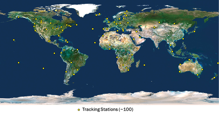
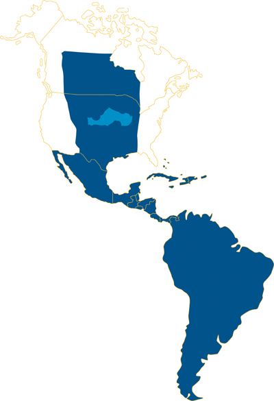
The CenterPoint RTX tracking network currently consists of around 100 stations, distributed across the globe, as shown in Figure 2. The CenterPoint RTX service is currently offered in North and South America, via satellite link, as indicated in Figure 3. Today the CenterPoint RTX service has been made available globally for all those with Internet access.
FIGURE 2. CenterPoint RTX tracking network distribution. (Click to enlarge.)FIGURE 3. CenterPoint RTX L-band satellite service coverage in the Western hemisphere.
Limiting Factors
To understand the limiting factors associated with global high-accuracy positioning, it is helpful to consider the simplified basic GNSS observation equations for carrier-phase and code measurements:
Φi=ρ+c(dT−dt)+T−Ii+λi Ni,
+Ai−ai+λi(WΦ−wΦ)+BΦ,i−bΦ,i+MΦ,i+nΦ,i
and
Pi=ρ+c(dT−dt)+T+Ii,
+Ai−ai+BP,i−bP,i+MP,i+nP,i
where:
Φi is the carrier-phase measurement for frequency i in meters;
ρ is the geometric distance between the antennas of the receiver and satellite in meters;
c is the speed of light constant in meters per second;
dT is the receiver clock error in seconds;
dt is the satellite clock error in meters per second;
T is the slant neutral atmosphere delay in meters;
Ii is the ionospheric delay for frequency i in meters;
λi is the carrier-phase wavelength for frequency i in meters;
Ni is the integer carrier-phase ambiguity for frequency i in cycles;
Ai is the combined receiver antenna offset and directional variation correction for frequency i in meters;
ai is the combined satellite antenna offset and directional variation correction for frequency i in meters;
WΦ is the receiver antenna phase wind-up effect, in cycles;
wΦ is the satellite antenna phase wind-up effect, in cycles;
BΦ,i is the carrier-phase receiver bias for frequency i in meters;
bΦ,i is the carrier-phase satellite bias for frequency i in meters;
MΦ,i is the carrier-phase multipath for frequency i in meters;
nΦ,i is the carrier-phase observation noise and other un-modeled effects for frequency i in meters;
Pi is the pseudorange measurement for frequency i in meters;
BP,i is the pseudorange receiver bias for frequency i in meters;
bP,i is the pseudorange satellite bias for frequency i in meters;
MP,i is the pseudorange multipath for frequency i in meters;
nP,i is the pseudorange observation noise and other un-modeled effects for frequency i in meters.
The feasibility of high-accuracy absolute positioning relies on the assumption that phase and code measurements on the different frequencies or on specific observation combinations are modeled quite reliably. This ultimately means that the parameters (or certain combination of them) of the two equations given are known very precisely, that is, with an accuracy of better than a few centimeters.
Having a global system where every component of the un-differenced GNSS observational model is well known requires advanced understanding and modeling of the involved GNSS-related effects. This is a general achievement of the RTX system.
(An extensive section here, encompassing satellite orbits and clocks, receiver clock error, antenna phase center odeling, phase wind-up effects, neutral atmosphere delay, and ionospheric delay, appears in the online version of this article, at env-gpsworld-integration.kinsta.cloud/rtx.)
Real-Time Network Processing
As previously stated, the RTX system works based on precise satellite information generated at processing centers and broadcast to users. The precise information employed by the systems comprises satellite orbits, satellite clocks, satellite biases, and other auxiliary information.
The requirements for the satellite orbits to be used in the global RTX system can be summarized as accuracy, continuity, robustness, and reliability. The satellite positions have to be accurate for obvious reasons, including the fact that orbit errors have direct impact on rover-position determination quality. Furthermore, because the RTX network process algorithms use ambiguity resolution, the reliability of the ambiguity determination is highly affected by the satellite orbits quality due to the distances between reference stations in the tracking network. The continuity requirement is put in place to avoid the need of handling observation modeling inconsistency over time for both network and rover processing.
For the same reason, the overall system employs techniques to properly handle switches between redundant orbit-processing servers without degradation of position quality. As one would expect, network processors have to be, in general, robust against the eventuality of poor data entering the system for various reasons. The RTX network processors employ a variety of quality-control techniques to ensure that only data with the highest expected quality is used for the computation of end products.
Finally, reliability is a very important factor for real-time orbit processing. At the current stage, the RTX real-time orbit processors are able to run for several months with virtually zero intervention from operators, while handling events such as satellites going through unhealthy periods and satellite maneuvers (during unhealthy period or not).
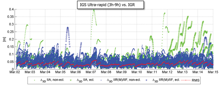
There are at least two strong reasons for justifying the need of implementing and running an RTX proprietary orbit processing server. The first one is simply the need of reliably meeting the above-mentioned requirements. The second one is that from an operational perspective, the RTX system is conceived in such a way that it does not rely on any external source of information to run at its full accuracy capability. Figure 4 shows the achieved orbit errors provided by IGS ultra-rapid products during two weeks of March 2011, where IGS rapid orbit products are used as truth. The ultra-rapid orbits are evaluated using the initial portion of the predicted arc, thus making use of the most reliable part of the predicted arcs as the products become available in real-time. In that case, neither accuracy nor continuity requirements for RTX processing are completely met.
FIGURE 4. IGS ultra-rapid orbit errors, as compared to IGS rapid orbit products.
Orbit Estimation. The orbit estimation in the CenterPoint RTX system is based on a combination of a UD-factorized Kalman filter estimating satellite position, satellite velocity, troposphere states, integer ambiguities, solar radiation pressure parameters, harmonic coefficients, and Earth-orientation parameters. The prediction step in the filter uses a numerical integration of the equations of motion in connection with a dynamic force modeling. Forces considered in the approach are: the Earth’s gravity field, lunar and solar direct tides, solar radiation pressure, solid earth tides, ocean tides, and general relativity.
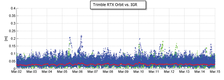
In RTX orbit processing carrier phase integer ambiguities are resolved in real-time. Also, the satellite orbit states are truly estimated in real-time and continuously adapted over time to better represent the current reality. This means that the satellite positions that are evaluated by the user have prediction times of no more than a few minutes since the last orbit processing filtering update, providing negligible loss of accuracy. Figure 5 shows the orbit errors obtained from the RTX orbit processor. Similarly to the previous figure, IGS rapid orbit products are used as reference. The time span is also the same as in the previous figure. The RTX real-time orbit components have a typical overall accuracy of around 2.5 centimeters (cm), and a 3D error accuracy of around 4 cm, considering IGS rapid products as truth.
FIGURE 5. RTX real-time orbit errors, as compared to IGS rapid orbit products.
Clock Estimation. Satellite clock estimation forms an essential part of the RTX system. It plays a fundamental role on positioning performance due to a number of reasons. Satellite clocks map directly into line-of-sight observation modeling, yielding into a one-to-one error impact from clocks into GNSS observables modeling. Due to the same strong relationship, it is of fundamental importance that clocks are generated in a way to facilitate ambiguity resolution within the positioning engine. The processing speed of a clock processor is also of critical importance, due to the fact that any delay in computing satellite clocks is directly translated into correction latencies when computing real-time positions on the rover side. For that matter, one should keep in mind that regardless how late satellite corrections get to the GNSS receiver in the field, positions have to be provided to the user as soon as the rover GNSS measurements are available. Therefore latencies typically introduce errors into the final real-time position. In this article, we define real-time positioning as the computation of positions at the time when the rover observables are available, regardless of the latency of the correction stream. This is a necessary concept in order to support dynamic rover GNSS positioning.
The RTX clock network processor was designed around the requirements discussed earlier. It computes clocks that are compatible with ambiguity resolution on the user receiver. As a matter of fact, the clock network processor itself employs ambiguity resolution for the generation of the RTX clocks. The processor architecture is based on an innovative design that allows processing data of several hundreds of reference stations, including all necessary steps such as data quality control, ambiguity resolution, and the final clock generation, within a fraction of second. The processing time of this kind of real-time network processor has to be minimized as much as possible in order to allow the processor to operate at 1 Hz, and to minimize the final correction latency at the rover end. Note that the final latency of the correction stream is a composition of three basic components: the time for the network data to arrive at the network processing server; the network processing time; and the correction transmission time to reach the final user. Figure 6 shows the typical total correction latency for the RTX system, when corrections are broadcast through a satellite link.
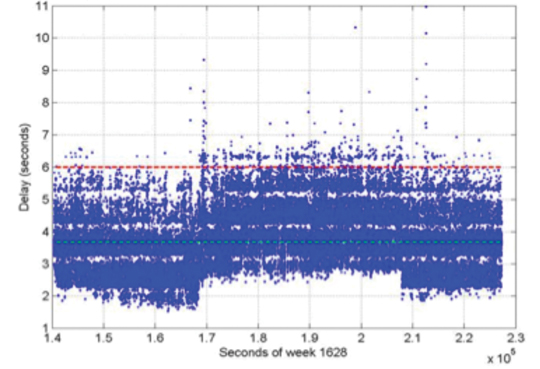
FIGURE 6. Typical RTX correction stream latency. The dashed green line represents the latency at 50 percent (3.7 s), and the dashed red line represents the latency at 99 percent (5.6 s).
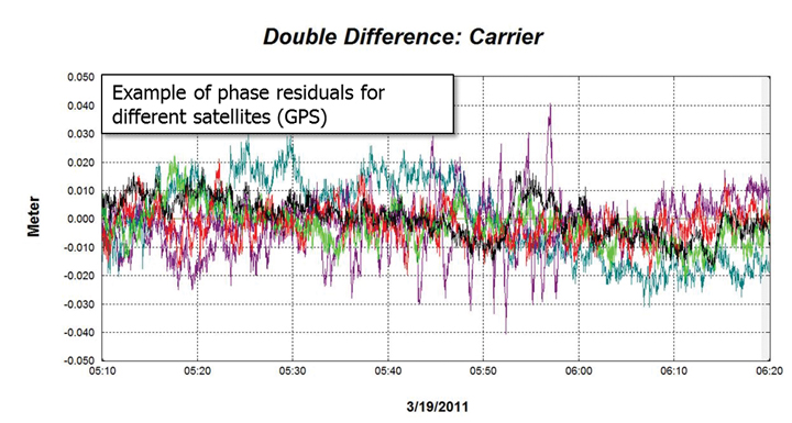
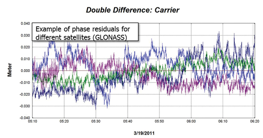
Unlike satellite orbits, satellite clock solutions are more difficult to compare directly. This is because different clock solutions might have offsets between each other, as well as behave differently due to differences in their GNSS reference time realization process as well as in their observation modeling approaches. That said, one way of verifying the quality of satellite clocks is to quantify how well it can be used to model actual receiver observation data. This can be in general achieved by applying satellite orbit and clock correction onto GNSS data and verifying the remaining residuals. Other quantities such as receiver coordinates have to hold their correct values for the residuals to be meaningful. In this case, the combined satellite orbit and clock error are assessed, and not just the satellite clock alone. For our purposes this is perfectly fine, since this is the way orbits and clocks are employed in rover positioning as well. Figures 7 and 8 show typical combined satellite orbit and clock errors at line-of-sight for different satellites. Figure 7 shows the ionospheric-free phase modeling error for GPS satellites, while Figure 8 is for GLONASS. Note that observations of a reference satellite (highest elevation at the time of observation) were reduced from the others. This was done in order to remove the receiver clock errors from the residuals. For both GPS and GLONASS cases, the observation modeling error after using RTX orbit and clock corrections is on average at the 1 cm level, with values typically less than 2 cm. The GPS satellite with outlying behavior in the plot below was setting at that time, and the increased amplitude of the residuals is mostly due to receiver observation errors such as multipath.
FIGURE 7. RTX clock quality (GPS) by means of corrected ionospheric-free phase measurements.FIGURE 8. RTX clock quality (GLONASS) by means of corrected ionospheric-free phase measurements.
Communication and Positioning
Once all satellite information is available, it must be compressed in a message that can be broadcast to the user in the field. The transmission of global corrections can be done in different ways, such as via Internet, in case the user has access to it, or using a satellite link. In the latter it is customary that corrections sufficient to cover the transmission satellite footprint are broadcast, rather than corrections complete enough to cover the globe. Firstly, because it is expected that users operating inside the satellite footprint will use the corrections only for that region, and secondly because bandwidth restrictions usually play a role in message design for satellite-based communication. The bandwidth restrictions not only enforce maximum bandwidth utilization below a certain limit, but also require that the utilization over time is homogeneous to ensure optimal usage of the satellite channel.
Furthermore, satellite signals are typically susceptible to frequent message-packet losses depending on the user environment, such as when a receiver is running under canopy. To mitigate packet losses, the message must be built in such a way as to allow the rover to continue operations with minimum loss of availability. In that case not only the message design has to foresee this type of situation, but also the message decoding, usage, and positioning algorithms have to be optimized to most favorably couple with the received messages. All these factors have been taken into account in RTX system communication design. A new message format was created to carry information on satellite orbits, clocks, observation biases, and other auxiliary information. The new RTX CMRx satellite messages deliver 1-millimeter resolution for satellite orbits and clocks.
The RTX positioning engine inherits several technological aspects from Trimble’s pre-existing RTK engine. This aspect makes the RTX positioning mode, and traditional RTK positioning modes (for example, single base, virtual reference station) easy to co-exist. Among other things, the new engine has been thoroughly tested and optimized for challenging tracking environments. In these scenarios the engine is presented with observation data collected with a high level of multipath and low signal-to-noise ratio, often producing cycle slips and gaps in the data. As previously mentioned, at the same time the correction stream also suffers packet losses and the correction data might not be completely available during certain masking conditions.
Positioning Performance. The RTX engine delivers typical final accuracies at 1–2 cm level for horizontal positioning, and 2–4 cm for vertical, 1-sigma. The final convergence of the system is achieved in 10 to 45 minutes after receiver startup. The time to converge might depend on several aspects, including satellite geometry and multipath conditions.
To overcome the increased convergence time as compared to traditional RTK systems, a number of features have been implemented as part of the RTX positioning engine, two of which are worthy of mention here. The Fast Restart feature allows users to power up or place the receiver at a known location and immediately obtain a converged solution. This is also applicable when users have not moved their equipment since the last RTX solution. This feature is quite valuable in agriculture applications, where the user typically does not move the tractor between RTX-steered field work activities, thus avoiding in the majority of cases the need to wait through a new convergence period before starting work, one or more days after the last system usage.
The second feature is also related to avoiding system re-convergence. The Bridging feature, an outage recovery capability, enables the RTX positioning engine to immediately recover from a complete constellation outage with loss-of-lock during any dynamic activity. This prevents the system from entering a new convergence phase in case the receiver loses track of up to all satellites in view, coupled with outages of up to a couple of minutes, such as when running behind a tree line, or under a bridge.
Accuracy
Horizontal position error obtained in real time in a receiver acquiring the RTX correction data through the satellite link in North America is shown in Figure 9. The receiver was running continuously for several days, and was located in Ames, Iowa. As displayed, the horizontal RMS was 1.4 cm, with a 95 percent horizontal error of 2.4 cm. These are typical values for satellite-based RTX horizontal performance.
FIGURE 9. RTX real-time horizontal positioning performance. Results obtained from a receiver operating in Ames, Iowa.
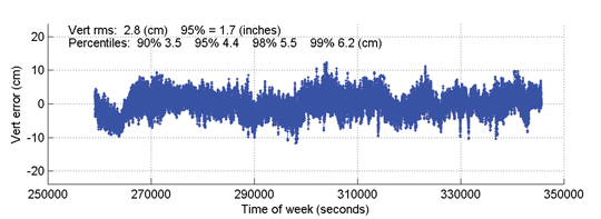
Figure 10 shows the vertical performance for the same receiver and time period: the vertical RMS was 2.8 cm, with 95 percent vertical error of 4.4 cm.
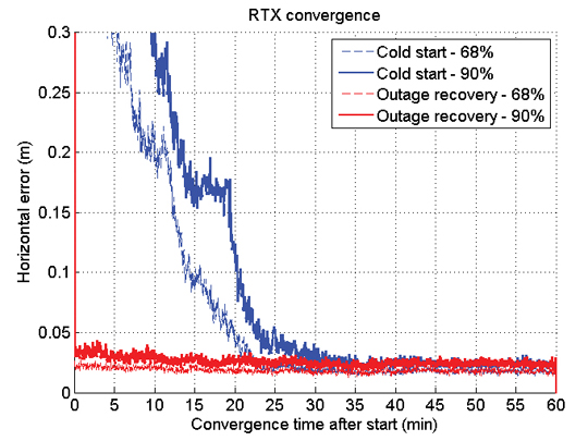
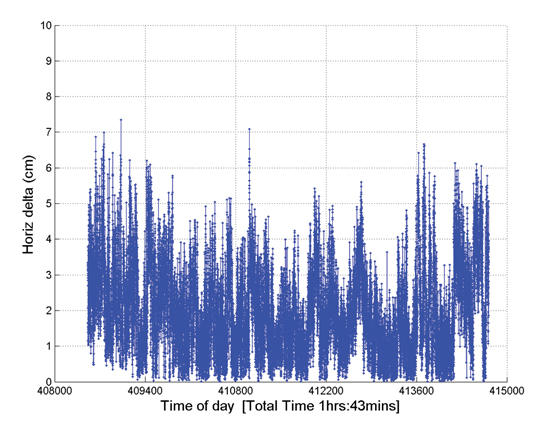
Time to Achieve Convergence. Convergence is directly connected to the level of productivity that can be achieved for actual field applications. In the following example a continuously powered RTX receiver was used to show an assessment of the RTX (re-)convergence capability. The receiver’s tracking of all satellites was disabled every hour by an antenna switch. Each outage lasted three minutes, during which times no GNSS satellites were tracked.
FIGURE 10. RTX real-time vertical positioning performance.Results obtained from a receiver operating in AMES, Iowa, US.
This procedure was repeated hourly for several days in order to gather enough performance runs to derive meaningful statistics. Figure 11 shows the resulting performance of this assessment. The standard cold-start re-convergence performance is indicated with blue lines, where the solid lines represent 90-percent performance and the dashed line represents 68-percent performance.
As the figure shows, the RTX system converged to better than 5 cm horizontal error after 20 and 25 minutes for 68 percent and 90 percent of the runs, respectively. Convergence time is correlated with a number of aspects, including satellite geometry and multipath environment. Because of these variations, the claimed RTX convergence time is between 10 and 45 minutes for full accuracy achievement.
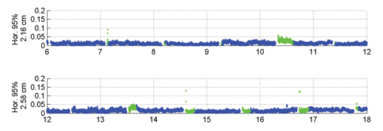
The red lines in Figure 11 indicate performance obtained with a second receiver, connected to the same antenna, and thus subject to the exactly same GNSS signal outages. This second receiver had the Bridging functionality enabled, and thus is expected to bridge the outages and phase cycle slips without resetting the positioning solution. The red lines confirm that the desired behavior is achieved. To better visualize what happens over time in this case, Figure 12 shows a few hours of the real-time results obtained with the receiver running with the Bridging functionality activated.
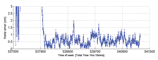
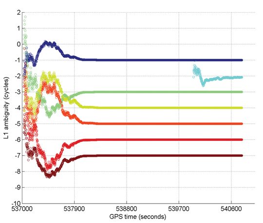
Figure 13 gives an example of Internet protocol (IP)-based RTX performance. This is a single run where the system converged to better than 5 cm (horizontal) in approximately 15 minutes. Figure 14 shows how the L1 ambiguities of individual satellites in view during that time converged.
FIGURE 13. RTX IP-based run example.FIGURE 14. Example of ambiguities convergence during an RTX IP-based run.
In these two plots, positioning convergence is, as expected, highly correlated with the ambiguities convergence to their final integer values in cycles. Note that satellites that come in after the overall solution is converged (for example, in light blue) achieve their final ambiguity values much quicker than during the position convergence phase, also as expected. The proprietary algorithms used for ambiguity resolution and validation in RTX allow the ambiguities to reliably converge to their integer values. Arbitrary integer number of cycles have been removed from the original ambiguity values to allow better simultaneous visualization of the ambiguities for several satellites.
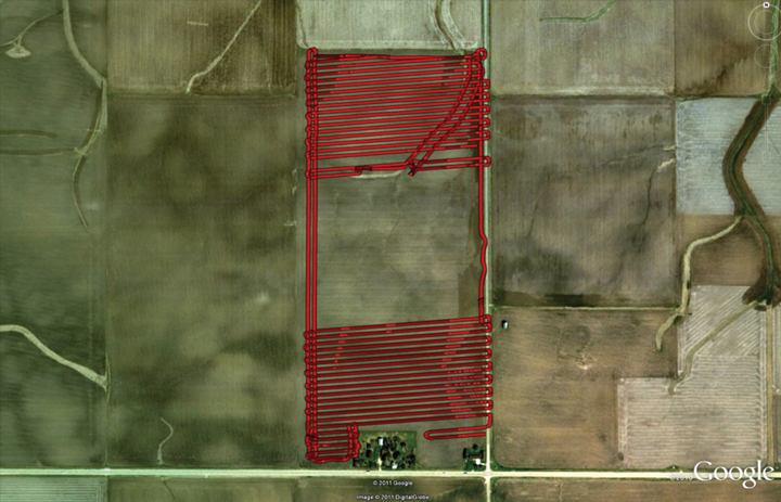
Optimizing the RTX system to work under different scenarios was necessary because the multipath and signal availability levels are reasonably different between running an antenna with a reference station setup and the actual user environment, where the data tracking conditions impose additional challenges on making high-accuracy positioning effective on a global basis, in a productive manner. Therefore, an extensive field test campaign was conducted during the pre-release phase of the RTX system. The next example shows RTX in-field performance for an precision agriculture application in Illinois. The setup is typical for agricultural use, with the antenna and receiver mounted on a tractor that ran for about 103 minutes. Figure 15 shows theactual track of the tractor; RTX corrections were received via satellite link.
FIGURE 15. RTX tractor field test track in Illinois.
The horizontal positioning performance for that field test can be seen Figure 16. The overall 2D RMS was 2.3 cm and the 95 percent horizontal error was 4.2 cm. Note that this position difference plot is between the RTX solution and a short-range single baseline (SBL) RTK solution providing truth. Therefore the numbers and plot actually show a combination of errors between the global RTX solution and the SBL solution to the local reference station.
FIGURE 16. Horizontal positioning results for a real-time RTX tractor field test in Illinois.
Nevertheless the error magnitudes achieved lie within the same range as in the previous assessments shown here.
Summary
RTX positioning brings together the advantages of positioning techniques that do not require local reference stations while providing the productivity of RTK positioning. Its deployment introduces innovations in GNSS network processing, as well as advancements in the rover global positioning algorithms.
RTX employs ambiguity resolution on a global scale for both network and rover processing, including GPS and GLONASS satellites in the solution. The delivery of this new technology is achieved through the CenterPoint RTX positioning service, capable of providing world-wide real-time centimeter-level accuracy without the direct use of a reference station infrastructure.
A longer version of this article was presented at the 2011 ION-GNSS conference in Portland, Oregon.
Rodrigo Leandro, Herbert Landau, Markus Nitschke, Markus Glocker, Stephan Seeger, Xiaoming Chen, Alois Deking, Mohamed Ben Tahar, Feipeng Zhang, Kendall Ferguson, Ralf Stolz, Nick Talbot, Gang Lu, Timo Allison, Markus Brandl, Victor Gomez, Wei Cao, and Adrian Kipka are members of the Trimble Engineering Team in Höhenkirchen, German
This discussion of current trends in location-enabled mobile devices takes as its foundation the different operating systems (OSs) for those devices. Why? For GPS/GNSS hardware units to be useful, there have to be software applications — apps — also riding on those units. Apps are totally dependent on the operating system. An analogy is that the operating system is the foundation of a house and the app is the house itself. The type of foundation you have drives what type of house you can build.
For example, no one is going to write an app today for Palm OS because that OS is essentially dead. While that’s an obvious one, a not-so-obvious one is Microsoft Windows Mobile. Most apps written for professional users are written in Windows Mobile, but Microsoft hasn’t done a good job of communicating its intentions regarding Windows Mobile, so users and developers think Microsoft may abandon it.
On the other hand, Android is gaining so much momentum. Will developers rewrite their apps from Windows Mobile for Android? Or for Apple’s iOS? Can they afford to? Can they afford not to? If they don’t, that would mean that fewer professional apps will be available for Android and iOS users. Will that mean Windows Mobile will be the OS for professional GPS/GNSS users, and conversely, will Android/iOS be the OS for consumer-level GPS/GNSS users? Taking it to a practical conclusion, according to the type of mobile computing device that you purchase, what kind of location application will you be able to use?
Smartphones. Apple iOS’s new Maps app will likely be the largest scale crowd-sourced app ever introduced.
PNDs Out-Smarted
For the past decade, GPS personal navigation device (PND) sales have burned white-hot. In 2007, Garmin experienced double- and triple-digit growth, selling more than 10 million units. TomTom grew from zero to hero and sold more than 9.5 million units in that same year. During that brief golden era, every consumer electronics company who was anyone took a stab at introducing a PND to get a piece of the action. As unlikely as it seems, Garmin and TomTom stayed on top, fighting off consumer electronic giants like Sony, Panasonic, Hewlett-Packard, and Philips, all orders of magnitude larger. PNDs ruled the GPS world during that era.
Download a PDF of our Mobile Computing Product Showcase.
At the height of that period of explosive GPS PND growth, Apple introduced a new generation of smartphone, the iPhone, in January 2007. At that time, there were approximately 17 million smartphones on the market. Nokia with its Symbian operating system led the pack at 63 percent of worldwide market share, Blackberry was the rising smartphone of choice, while Microsoft Windows Mobile operating system captured 18 percent. Google’s Android operating system had not yet debuted.
It’s amazing how a mass-market technology, so personal to us all, can change so quickly. Today, Google’s Android operating system dominates the smartphone market (roughly144.4 million smartphones were sold in Q1 alone of 2012, according to Gartner Research) with a 56.1 percent share. Apple’s iOS follows at 22.9 percent; Symbian (Nokia) has fallen from leader to bit player at 8.6 percent, and keeps company in the low rungs with RIM/BlackBerry (6.9 percent), Samsung’s Bada (2.7 percent), and Microsoft Windows (1.9 percent).
The trend is clear. Android and iOS are cleaning up at the expense of all the others. Is it any coincidence that these two are the ones making the most of their maps and nav? More on this in a moment.
By the way: every one of the 144.4 million smartphones that shipped in the first three months of 2012, no matter what operating system it ran on, carried a GPS receiver inside, typically a chipset from Broadcom, CSR/SiRF, u-blox, Qualcomm, or Texas Instruments. That spells trouble for Garmin and TomTom. Google and Apple are doing to Garmin and TomTom what Microsoft did to NetScape with Internet Explorer.
Even with GPS PND prices at an all-time low, Google’s Navigator, with high-quality, PND-like turn-by-turn street navigation, is included on Android smartphones free of charge. Apple is following suit. Just last month, Apple introduced the Maps app for turn-by-turn street navigating as well as real-time traffic information. With more than 100 million iPhones behaving like traffic sensors, Apple’s Maps app will likely be the largest scale crowd-sourced app ever introduced.
What does this mean to Garmin and TomTom? The numbers don’t lie. In February 2012, TomTom reported a 40 percent decrease in GPS PND sales for Q4 2011 compared to Q4 2010.
Tablet Computers
For another wild ride, take a look at the tablet-computer market. The tablet has been around for many years. I remember playing with them in the 1990s when they were horribly expensive ($3,000–$5,000). The price, a limited outdoor-viewable display, and power usage all combined to squash unit sales. Only a few manufacturers such as Fujitsu had the determination to stay. That all changed in 2010 when Apple introduced the iPad.
Prior to the iPad rollout, tablet computer sales were limited primarily to business users. Healthcare provided a particular arena for Fujitsu and others to focus on, and there were a few other markets that were not very price-sensitive, and so receptive to the tablet. The iPad blew away that $3–5K price point (iPad 2, $629) and brought the tablet experience to the average consumer. The result? Roughly 67 million units sold since its introduction, far surpassing all tablet computer unit sales in history in just two years. Apple hit a sweet spot, for sure.
The iPad catalyzed the tablet industry for two reasons:
It opened the eyes of the consumer to the applications of a tablet computer.
It drove the price-point expectation of all tablets down.
Of course, the iPad has its limitations. It runs Apple’s proprietary operating system, iOS, so you are limited to the number of apps written for that platform. It also lacks horsepower to run more challenging programs that an Intel or AMD-based computer can breeze through. From a GPS/GNSS perspective, certain models of the iPad sport a GNSS chipset (from Broadcom) similar to mobile phones; however, because of the way the GPS functionality is designed into the system, accuracy is limited to a few meters at best. Power GPS/GNSS users would love it if Apple would implement serial port profile (SPP) in its Bluetooth software. Then, GPS/GNSS users could attach any Bluetooth-compliant GPS/GNSS receiver they like, even RTK-capable receivers for centimeter-level accuracy. But Apple doesn’t seem interested.
As in the mobile-phone market, Google is making a strong tablet play with its Android operating system. Google’s device-agnostic operating system is attracting tablet hardware makers in droves with iPad-like tablet computers, notably Samsung Galaxy (with GPS) and Amazon Kindle Fire (no GPS). Also, there’s an interesting link between mobile phones and tablets. Gartner reports that 40 percent of user apps run on both mobile phones and a corresponding tablet computer. This is significant because the operating system may well drive the tablet purchase. For example, a person with an iPhone is more likely to buy an iPad than a Samsung Galaxy, which runs Google Android.
However, Android has not achieved the dominance in the tablet computer space that it has in smartphones. iOS (iPad) held 67 percent market share in 2011, falling to 61 percent in 2012,but still retaining the pole position. Android is a strong second with 29 percent in 2011, rising to 32 percent in 2012, according to Gartner. No other operating system even comes close.
Gartner forecasts show that Android will eventually approach iOS in market share, and my guess is that it will overtake iOS within five years. Apple’s proprietary system will catch up to it. While GPS/GNSS chipsets aren’t as widely integrated in tablets as they are in mobile phones, that will change as GPS/GNSS use becomes even more ubiquitous. Further, there are plenty of ways to add GPS to a non-GPS model via Bluetooth, PCMCIA, and USB.
Android supports Bluetooth SPP, or a derivation of it, so you can connect any Bluetooth SPP-compliant GPS receiver that you like and not be limited to the receiver chipset the tablet engineer decided to design into the system.
]Although PDAs have an embedded receiver, they are lower-precision systems, in the 1- to 5-meter range, largely due to poor antennas. For higher precision requirements, these are used as field data collectors connected to an external antenna and/or a high-precision GPS/GNSS receiver.Handheld PDAs
Handheld personal digital assistants (PDAs) were all the rage 10 years ago when Compaq Computer Corp. introduced the iPAQ H3100 running Microsoft’s PPC2000 (Pocket PC) operating system, the precursor to Microsoft’s Windows Mobile operating system. The iPAQ made a strong run through 2009, with the last models running Windows Mobile 6 before smartphones became powerful enough to negate the purpose of the PDA.
While we probably will never see another introduction of a new iPAQ-branded PDA, it was a useful device and an inexpensive handheld for interfacing to GPS/GNSS receivers. Albeit a niche market, there’s still a demand for such handhelds for field data collection.
According to the nature of capitalism, where there’s a demand, suppliers will show up. Since the iPAQ has faded, and smartphones aren’t yet well-suited as field data-collection devices, a new breed of semi-rugged and rugged PDAs has emerged in the past year from small, niche-oriented companies. Examples include the SXPad from Geneq, Juno 3 series from Trimble, and the Mesa/Rampage 6 from Juniper Systems/SDG Systems.
These devices, with GPS/GNSS receivers embedded, are not built for the average consumer. Their prices are higher — but coming down — and they are more rugged; some are water-resistant, some waterproof.
In a nutshell, PDAs went professional, targeting organizations that need maximum data-collection productivity from field personnel. Although they have an embedded receiver, they are lower-precision systems, in the 1- to 5-meter range, largely due to poor antennas. For higher precision requirements, these are used as field data collectors connected via Bluetooth to a high-precision GPS/GNSS receiver.
Although the professional PDA market is not immune to the operating-system wars we’ve seen in mobile phones and tablet computers, it’s a bit stickier. Professional data-collection apps have been written almost exclusively around the Microsoft Windows Mobile operating system. These niche software programs are written for relatively small audiences (compared to the mass-market apps on smartphones), and it can be economically tough to justify porting the apps to iOS or Android. Therefore, the professional PDA market has been slower in adopting iOS and Android.
Microsoft hasn’t helped the cause. It stopped certifying new products with the Windows Mobile operating system, creating confusion in the user community. Is Microsoft exiting the mobile device business? Not according to the company. It appears that it has split the mobile device business into two operating systems. Smartphones will run Windows Phone, and other mobile devices will run Windows Embedded Handheld, which is compatible with Windows Mobile.
The problem, the confusion, and the frustration come from the fact that the Windows Phone operating system is not compatible with Windows Mobile (or Windows Embedded Handheld). Microsoft split the market between smartphones and other Microsoft-driven mobile devices. Given Gartner’s research that 40 percent of users’ smartphone apps also run on a tablet device, this means that Microsoft is going to either change that dynamic or suffer the consequences.
No matter which direction mobile devices take, be it phone, handheld, or tablets running Android, iOS, Windows, or something we haven’t yet seen, embedded GPS/GNSS functionality will remain the centerpiece of location technology in all mobile devices. Even more exciting are the new GNSS signals and constellations in the next five years that will bring unprecedented accuracy to all mobile devices, driving the development of a tremendous number of new apps to exploit the improving accuracy.
Eric Gakstatter is contributing editor for survey at GPS World magazine and the editor of Geospatial Solutions. He has spent the past 20 years in the GPS survey/mapping industry, using many brands of GPS equipment and software. He is a non-partisan advocate for the GPS user community, and a frequent speaker at user and technical conferences.