Category: Survey

  • What’s Going to Happen When High-Accuracy GPS is Cheap?

    Last week, as you may have heard given the multiple launch delays, the United Launch Alliance (a Lockheed and Boeing joint venture), under contract with the U.S. Air Force, successfully rocketed a new GPS satellite into orbit.

    The GPS satellite launched into orbit last week wasn’t just any other GPS satellite. It was the first of a new generation of GPS satellites that are going to change the way surveying, engineering and construction data is collected and processed in the future. Its new features are going to profoundly transform surveying, engineering and construction. I’m not exaggerating.

    Before you stop reading because you think you’ve read this already in my other newsletter, Geospatial Solutions Weekly released earlier this week, hang in there because although some of it is the same, I’ve added some surveying-specific comments.

    First of all, it’s important to understand that this is going to happen. It’s not a matter of if, but rather when. What I mean is the price of high-accuracy GPS is going to be very inexpensive, both horizontal and vertical, and it’s going to dramatically affect your business.

    Here’s why.

    The new L5 signal will eventually (when it’s being broadcast from enough satellites – more on that later) significantly transform GPS receivers in two ways:

    1. It will result in high-accuracy GPS receivers being much cheaper and smaller.
    2. It will make collecting high-accuracy GPS data much more convenient for the average person.

    Let’s examine in more detail.

    Why will high-accuracy GPS receivers be cheaper and smaller?

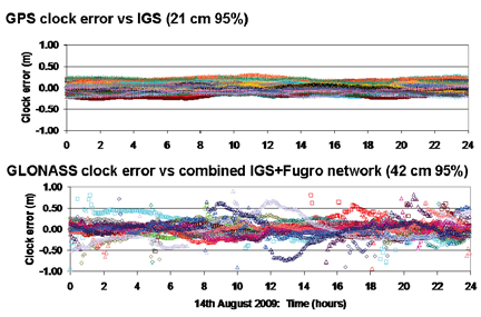
    Today’s GPS dual-frequency receivers (L1/L2) can achieve a high level of accuracy (1 cm) in a short period of time, as little as a few seconds. But, they are expensive. An entry-level GPS dual-frequency receiver is a few thousand U.S. dollars. The primary reason is because there is a limited number of companies that design GPS dual-frequency receivers for surveying, maybe a dozen or so. Why is there a limited number of manufacturers? The answer is because the original L2 was not an open signal. In the 1980s, some very smart engineers figured out how to utilize L2 (designed for military use only) in commercial receivers. When they developed those techniques, the companies were smart enough to patent them. There are so many patents in place that it makes it very difficult for a new designer to enter the traditional GPS dual-frequency market, whether it’s surveying, machine control, GIS, or whatever.

    Unlike the original L2, L5 is an open signal. Its specification is published for anyone to use. No license fee. No receiver tax. Nothing.

    Without any patent blocks, any company in the world is free to develop a GPS dual-frequency (L1/L5) receiver that would be just as accurate, and arguably more accurate, than today’s L1/L2 GPS dual-frequency receivers.

    Looking back on the history of electronics, within and outside the GPS industry, we know that increased competition usually results in lower prices to the consumer and improved product quality.

    Take, for example, GPS L1 receiver chips used in personal navigation devices and mobile phones. Those chips are available today for less than $3 each. Fifteen years ago, much less powerful GPS L1 receivers were $200 each and 10 times larger.

    Mark my words: you will see a similar trend with high accuracy GPS dual-frequency receivers. GPS dual-frequency receivers will be sold at prices you can’t imagine today, allowing surveyors, engineers, contractors, GIS folks, biologists, ecologists, etc. (and an educated general public) to collect high-accuracy data (horizontal and vertical) very inexpensively.

    The only thing holding this trend back is the availability of L5. It needs to be broadcast by  about 24 GPS satellites. That’s going to happen somewhere between 2018 and 2020. Of course, GPS designers will be working on their receivers long before that.

    Why will collecting high-accuracy GPS data be much more convenient for the average person?

    First of all, the cost of high-accuracy GPS dual-frequency receivers will plummet significantly due to the open L5 signal. This will spur a fantastic amount of innovation and competition among a large number of receiver designers, especially in the consumer electronics market. Surveyors, engineer, contractors, GIS folks, etc. will benefit greatly from the consumer electronics industry because the high volumes in the consumer market will further spur innovation and cost reduction.

    Oddly enough, at that time, the most expensive part of a high-accuracy GPS receiver may be the antenna. The consumer electronics market won’t accept the type of high-accuracy GPS antenna we need (too big/bulky), so the limited number of antennas means you’ll pay a higher price, maybe a $100, maybe $200.

    If you have a minute, you might want to browse this article by Dr. Frank van Diggelen. Essentially, he says that consumer GPS receivers in your mobile phone, PND, etc. can be as accurate as a GPS receivers built for high-accuracy surveying. The reason they aren’t, he says, is due largely to the inferior antenna being used in mobile phones, PNDs, etc. Now, I’m not saying I buy everything he’s writing, but he’s a lot smarter than I am with regards to GPS, and I do have enough experience to know that antennas can make a big difference in receiver performance.

    What you’ll see, eventually, is GPS dual-frequency (L1/L5) receiver technology in consumer electronics, which means high-accuracy positioning at consumer prices. Take it a step further and one can make the statement that high-accuracy positioning will be in the hands of the consumer. A knowledgeable consumer will be able to take a  low-cost, high-accuracy GPS dual-frequency receiver and collect (or have others collect) an amazing amount of valuable data (think high-accuracy vertical) that would otherwise be too expensive to collect using today’s technology.

    That is where we are headed, guaranteed.

    Wildcards

    Other GNSS

    The time-frame estimation I made above (2018-2020) for a full (24-satellite) constellation of GPS satellites broadcasting L5 is based solely on the activities of the U.S. government. Keep in mind that the U.S. government can’t exceed the 2020 deadline because December 31, 2020, is when the U.S. Air Force says it will stop supporting legacy GPS L1/L2 dual-frequency receivers. So, the end of 2020 is the worst-case scenario.

    Of course, the U.S. isn’t the only country working on GNSS. Europe’s Galileo system also utilizes L1 and L5. It’s possible that in the 2014 timeframe, the U.S. could have a dozen GPS satellites broadcasting L1/L5 and Galileo could have a dozen Galileo satellites broadcasting L1/L5. Because the U.S. and Europe have been working so closely together to ensure GPS and Galileo work together seamlessly, having 12 Galileo satellites broadcasting L1/L5 is the same as GPS broadcasting L1/L5.

    China is also working on a GNSS called Compass/BeiDou. Although China is very tight-lipped with its intentions, it’s possible China could launch some satellites in orbit that may contribute to an L1/L5 solution, but China is a serious wildcard.

    L2C

    Some of you may be wondering why I haven’t included GPS L2C in the discussion. L2C is an open GPS signal much like L5. There are currently seven GPS satellites broadcasting L2
    C. Not including Galileo, there will be 24 GPS satellites broadcasting L2C before there are 24 GPS satellites broadcasting L5. In fact, some designers may decide to develop L1/L2C receivers. However, Galileo isn’t supporting L2 so while there will probably be triple-frequency receivers (L1/L2C/L5), my guess is that the standard will be L1/L5, because the third frequency isn’t going to buy you much.

    Conclusion

    No other conclusion can be drawn but that in the future, as soon as 2014 and as late as 2020, high-accuracy GPS receivers (cm-level in both horizontal and vertical) will be in the hands of anyone with a few hundred dollars to spend. This will be consumers as well as surveyors, engineers, contractors, GIS folks, and many other folks who see value in spatial data. They will have easy access to a fantastic new tool that will allow them to collect high-accuracy, horizontal and vertical data, at a very low cost and very conveniently. I keep referring to vertical accuracy because accurate vertical data is much more expensive to acquire with the technology that exists today, GPS and otherwise. Not so in the future. When one really thinks about the value of accurate low-cost vertical data, the numbers of applications are mind-boggling and will certainly send all disciplines that use spatial data in a new direction.

    Perhaps no discipline will be more affected by this technology advancement than surveying. If you’re retiring in five years, you can probably get away with not thinking about this. But, if you’ve got more than that left in your career, you really need to consider what direction you want to go.

    The bad news is that you have to change. Change is stressful, especially at mid-career, but you don’t have a choice if you want to enjoy a career in surveying. Technology is transforming surveying. You know it because you’ve been feeling the squeeze. You’ve seen that engineers and contractors have acquired technology tools to bring some activities in-house. Machine control is an obvious one. In just a few years, you likely won’t be doing the same sorts of tasks you’re doing today. There will be much more emphasis on data management and data analysis than on data collection (less field time, more office time). Of course, there will still be a need for people in the field, but that’s not where the professional wage is going to be earned. Those in the field will only have jobs, not careers. The well-paying careers will be in the office (either home office or business office or mobile office).

    The good news is that there’s more opportunity than ever before. I can’t count the number of times I’ve had people from different organizations (public and private) ask me if I knew someone who could help solve their geospatial problem. Sometimes, it’s a problem combining data sets. Sometimes, it’s a problem interpreting the data they have as well as finding or collecting new data. Guess what? They aren’t looking in the telephone book (yellow pages) to find someone to help solve their problem. In fact, in some cases they don’t even care if you live in the same country as they do. True, you may have to travel to their office, but they don’t care as long as you solve their problems. I realize this may be a strange concept to many of you, but the Internet has made the world a lot smaller than it used to be. Your clients don’t have to be located within 200 miles of your office. You can have clients in different counties, states, provinces, and even countries! When you start letting go of the idea that your clients need to be geographically close to you, suddenly your business prospects start to look bright. When you limit your ten-person company to clients located within 100 miles in rural Alabama in this economy, you’re going to starve. When you release that limit and start thinking and acting regionally, statewide, nationwide, or worldwide, all of the sudden there’s a lot more opportunity to keep your employees working.

    One important note

    In order to take advantage of the opportunities I mentioned above, you have to expand your knowledgebase. There’s no choice. It’s either that or you’re bagging groceries at Walmart. Technology is changing and its forcing changes in your business, so you must adapt to those changes. Recently, I wrote about a technical session at the ACSM/GITA conference I attended called the Surveying Body of Knowledge (SBoK). Although I may have some differences with some of the SBoK committee member’s intentions, the concept is right. SBoK does a good job of defining the different disciplines in which surveyors can diversify. Briefly, the five areas are:

    1. Positioning (field data collection)
    2. Imaging (photogrammetry/remote sensing/3D scanners/LiDAR/)
    3. GIS (mapping/cartography)
    4. Law (boundary/real property/business law)
    5. Land development (construction/planning/development)

    The idea is that if one discipline is weak, such as positioning, in the current economy, then you could shift your business in another direction where you are qualified, such as GIS or imaging. You certainly don’t need to be qualified in all five disciplines, but having three or four in your pocket gives you a lot of flexibility when the economy is as weak as it is now.


    Thanks, and see you next time.

    Free Webinar on June 24th

    On June 24 (was originally scheduled for June 22), I will be conducting a free 60-minute webinar on “GIS Mapping for Forestry, Agriculture, and Other Natural Resource Professionals.” I will discuss GIS mapping software tools/concepts/techniques as well as GIS mapping hardware such as GPS receivers, digital cameras, and laser rangefinders. Although focused on natural resources, it will be relevant for all people interested in GIS mapping, which could be utility companies, municipalities, transportation organizations, etc.  Sign up now by clicking here and submit questions in advance.

    Follow me on Twitter at

    https://twitter.com/GPSGIS_Eric

  • GPS, GLONASS, and SBAS Webinar Follow-up

    Normally, my column following a webinar is dedicated to Q&A follow-up from the webinar. However, immediately following the April 22 webinar, I traveled to Phoenix, Arizona, to attend the ACSM/GITA conference, which I wrote about earlier this month.

    This column is dedicated to answering questions I didn’t address during the webinar. Also, I always find the results from the polls I conduct during the webinar very interesting.

    Poll #1: Have you or your work crews had to stop or alter your work pattern due to the lack of GPS satellites?

    Total votes: 128, Yes: 73%, No: 27%

    Gakstatter comment: This is consistent with other polls I’ve conducted regarding GPS satellite availability. The new GPS 24+3 configuration will help mitigate this problem. Read more about the new GPS 24+3 configuration in a three-part series I wrote earlier this year.


    Poll #2: How often do you upgrade your GPS equipment?

    Total votes: 113

    Gakstatter comment: There’s no clear pattern here except to say that 46% of the users wait until at least 3 years before they consider upgrading their GPS equipment. That makes sense to me.


    Poll #3: Does any of your GNSS equipment utilize GLONASS?

    Total votes: 115, Yes: 39%, No: 61%

    Gakstatter comment: When considering the result of this poll, keep in mind that there are very few “mapping-grade” receivers that are designed to utilize GLONASS. For example, there are very few, if any, sub-meter receivers that utilize GLONASS, primarily due to the lack of correction sources. SBAS doesn’t support GLONASS, DGPS (radiobeacon) doesn’t support GLONASS, and most CORS do not support GLONASS. Only recently did OmniSTAR begin supporting GLONASS. I think this trend will continue, although I doubt that SBAS or DGPS (radiobeacon) will support GLONASS in the foreseeable future.

    Poll #4: Does any of your GNSS equipment utilize SBAS (WAAS/EGNOS/MSAS) as a primary source of corrections?

    Total votes: 111, Yes: 60.5%, No: 39.5%

    Gakstatter comment: This poll result doesn’t surprise me. Given that SBAS corrections are widely available, free of charge, reasonably accurate, and require no action by the user, it makes a lot of sense they are being used.

    Following are some of the questions that were posed by the audience during the webinar:

    Question #1: I am not sure, but when you say you’re “pushing” something out to us, it sounds like your trying to “push” something on us. Just a comment.

    Gakstatter: I’m sorry about the webinar-speak. When I say “pushing the next slide,” that means I’m changing slides. I may change the way I say this. Thanks for your comment.

    Question #2: Can you correct GLONASS signals with WAAS or other real-time technologies?

    Gakstatter: WAAS (or any SBAS) doesn’t support GLONASS. Neither does DGPS (radiobeacon). This doesn’t mean that GLONASS measurement can’t be used, but you’ll be using uncorrected measurements to augment SBAS-corrected measurements. A case where it may be useful is when you’re mapping in an environment where there are a lot of trees. You might only have four GPS satellites visible that are being corrected via SBAS. In that scenario, there might be value in utilizing measurements from GLONASS satellites just to improve the PDOP, even though the GLONASS measurements are uncorrected.

    Question #3: Do you feel manufacturers will begin to release lower-end mapping-grade GPS receivers with L2C and L5 functionality in the future?

    Gakstatter: Yes, I do, but it will be a few years before there are enough satellites broadcasting an L5 signal. I think what you’ll end up seeing are inexpensive L1/L5 receivers (Galileo doesn’t support L2). They will not only be able to provide mapping-grade sub-meter, decimeter) but also RTK accuracies (cm-level). Since L2C and L5 are open civil signals, you won’t see the patent blocks that restrict competition for L1/L2 receivers like you do today.

    I’m not saying L2C will not be supported at all. I think there will be L1/L2C/L5 receivers, but I think you’ll see L1/L5 on lower-end receivers.

    Question #4: There is apparently some degradation of accuracy when using GPS and GLONASS for RTK. Have there been any rigorous studies quantifying this that you are aware of?

    Gakstatter: I’m not sure I’d say I believe there is degradation in accuracy, but I wouldn’t count on GLONASS to improve accuracy. The value of GLONASS is improving productivity. Since it adds several satellite signals to the solution, it effectively eliminates GPS “brown-out” periods so RTK can be used 24/7. There was a rigorous study released by The Survey Association in the UK. The report focused on network RTK. They tested both GPS and GPS+GLONASS. You can download a copy of the report here.

    Question #5: Does using GLONASS-capable receivers shorten the observation time required for fast-static points?

    Gakstatter: My first thought is yes since generally more observables equates to shorter occupation time, but I would check with the manufacturer and follow their recommendations. Honestly, I’ve only used fast-static with GPS-only receivers so I don’t have any personal experience with your scenario.

    Question #6: When is GLONASS-K launch scheduled? When can we receiver a valid CDMA signal?

    Gakstatter: The first GLONASS-K satellite is scheduled for launch later this year. I haven’t seen a launch schedule beyond that. A representative from the Russian Space Agency is scheduled to present at the Institute of Navigation (ION) GNSS conference in September, so I’ll probably learn more at that point. However, it’s a lengthy process. It’s not just a matter of launching satellites. There are many other variables and unknowns such as the control segment and user equipment compatibility. I think it’s safe to say that we are a few years away from having a minimal GLONASS satellite constellation broadcasting CDMA.

    Question #7: The visibility plots show one extra satellite in the “after” plots. Was that intentional? I would have expected there to be an improved number of satellites visible when one more was added to the plotted constellation.

    Gakstatter: Good catch. In the “after” scenario, I set SVN-49 healthy, which it is currently not. The reason I did this was because SVN-49 is in an important slot in the 24+3 configuration. The status of SVN-49 is still undecided, but if they decide to not set it healthy they will move another satellite to take its place in the 24+3 configuration. If I would have kept it unhealthy in the “after” scenario, it would have only s
    hown a 24+2 configuration. Clear as mud?

    Question #8: Is 24+3 the solution to the blackout problem from now to 2014 stated by the GAO Report from last year?

    Gakstatter: The definition of the 24+3 configuration had been around before the GAO Report. Personally, I don’t think the GAO Report had anything to do with 24+3. The 24+3 configuration just helps optimize the current satellites in orbit, whereas the GAO Report addresses the attrition of GPS satellites outpacing the addition of GPS satellites.

    Question #9: Cellphone question: Is the move to 24+3 likely to degrade indoor GPS coverage – fewer peak sats => lower probability of seeing 4+ sats indoors?

    Gakstatter: Interesting question. My first thought is probably so, although I think it would be a temporary problem. Assuming Galileo keeps pushing forward, that would be a big help for cellphone users, both indoors and outdoors.

    Question #10: GPS Satellites are getting beyond the design life…is the USA behind schedule in satellite updates?

    Gakstatter: GPS satellites have been unbelievably reliable. PRN-24, the oldest operational satellite, has been in operation since August 30, 1991. Since they have been so reliable, there hasn’t been as much pressure to launch GPS satellites. Prior to the 24+3 initiative, the minimum guaranteed constellation was 24 satellites. It costs $50-60 million to build each GPS satellite and another $150-200 million to launch it. With the GPS constellation hovering around 30 satellites these past few years, and government budgets tightening, I think it’s clear that the pressure to save money has resulted in a more relaxed launch schedule.

    The delay in the Block IIF satellite (the first one being launched this week) was not a result of the above, but rather technical and program management mis-steps. The GAO Report was particularly critical of the IIF development.

    Question #11: Do you see any future for ground-based free systems such as those broadcasting corrections in LF/MF radio, like the Coast Guard broadcasts?

    Gakstatter:
    There is an interesting debate between DGPS (what you mention) and SBAS. The DGPS infrastructure has been in place and working reliably for mariners for better than a decade. Funding for DGPS seems solid for marine navigation, but less stable for inland-based applications (like the U.S. NDGPS system). I think the future of DGPS for mariners is solid for the next 10 years. Once there is a full constellation of satellites broadcasting GPS L5, the value of DGPS will be questioned.

    Question #12: Will WAAS, EGNOS, etc. be needed after L1/L5 receivers can measure the iono effects themselves?

    Gakstatter: I think it comes down to integrity. If the L1/L5 combo can deliver integrity that safety-of-life applications require (such as aviation), then one has to question the value of SBAS. My gut feeling is that the L1/L5 combo can’t and that some sort of augmentation will be needed to attain the integrity level required.

    Question #13: What are your thoughts concerning Compass? Do you feel this will eventually be applicable for public use as part of a functioning GNSS?

    Gakstatter: Compass is the GNSS wildcard. Since the Chinese aren’t particularly forthcoming with their plans, it’s hard to say. But I’m not sure that matters. With a full constellation of GPS, GLONASS (CDMA), and Galileo satellites in the future, that’s around an average of 25+ satellites in view at any one time during the day. If China doesn’t play well with others in a timely fashion, the user community won’t care what Compass brings to the table.

    Question #14: If my current GPS receiver is not ready for L2C and L5, do I have to buy a new GPS or I can upgrade software/firmware later so that I can still use it?

    Gakstatter: You’ll have to trade-in. Some might be upgradable to L2C, but L5 is a different story. It’s a completely different frequency. That affects the receiver as well as the antenna.

    I wasn’t able to address all of the questions here, so look for more in the next newsletter. Particularly I’ll cover some discussion about reference frames, SBAS and L5.

    Look for announcements in the next day or so about the Block IIF GPS satellite launch. It’s scheduled for Friday, May 21. It’s a new era with the first GPS satellite to broadcast an operational L5 signal.

    Thanks, and see you next time.

    Follow me on Twitter at http://twitter.com/GPSGIS_Eric

  • ACSM/GITA Conference Coverage

    The annual ACSM (American Congress on Surveying and Mapping) isn’t what it used to be. Attendance was way down and the number of exhibitors is way down. The technical content, however, was still pretty good. In fact, I’ve included links to several videos I recorded at the ACSM/GITA conference.

    This year, the ACSM conference was co-located with the GITA (Geospatial Infrastructure & Technology Association) annual conference. This made the trip worthwhile. By themselves, both conferences are becoming too small for most attendees (and therefore, exhibitors) to attend.

    GITA is a GIS conference targeted at the global geospatial community, but in reality it attracts infrastructure geospatial users such as electric/gas/water utilities and local government.

    This mix of ACSM and GITA is interesting and was a great opportunity for surveyors. While the economy is starving surveyors who are in the typical boundary and land development markets, the GITA crowd, in my estimation, are in dire need of a GIS-versed land surveyor.

    There are many topics that were interesting and I thoroughly enjoyed most of the ones I attended, but there are two points I want to address about this conference:

    1. Surveying/GIS collaboration discussion
    2. Surveying Body of Knowledge discussion

    If I can write fast enough, there is a third I’d like to tackle regarding the Driven By Data discussion. If not in this column, I’m sure I will touch on it in a future column or maybe in my Geospatial Solutions Weekly column.

    Surveying/GIS Collaboration

    One of the major benefits of co-locating the ACSM and GITA conferences is that it gives attendees a chance to mix it up with the “other side.” History has consistently demonstrated that it’s always easier to view the “other side” with a certain level of antipathy from afar. However, when one learns more intimately about the adversary’s intentions and struggles, that antipathy eventually turns towards empathy and appreciation. I recall listening to a US Veteran of World War II talking about fighting the enemy. I’m paraphrasing, but it went something like this:

    “I believed in what we were doing and fighting the enemy was just doing my job. In those circumstances, we were enemies. Under peaceful circumstances, however, we may have been neighbors and we may have even been good friends.”

    Land surveyors and GIS folks should be good friends. They both have a lot to gain from a positive relationship and a lot to lose with an adversarial relationship, with the former standing to lose the most.

    Rudy Stricklin presented a very good session entitled “Professional Land Surveyors and Geospatial Professionals Building Bridges in Arizona.” In the presentation, he describes the process surveyors and GIS folks went through in Arizona to collaborate and find a common ground to work from. I’m not saying I necessarily agree with everything that was presented or enacted in Arizona, but Rudy’s consistent and often used terms like “collaboration” and “inclusive” certainly conveyed the team-building spirit and positive attitude needed to build a long-term relationship. The bridge-building process presented by Rudy is a model that would be difficult to go wrong with in a similar endeavor by another state, province or local/regional government.

    I recorded the presentation in its entirety. It’s in five parts with each being about 10 minutes in length. I suggest listening to the first segment as he paints the broad picture. However, the entire presentation is well worth your time.

    Part 1 – Professional Land Surveyors and Geospatial Professionals Building Bridges in Arizona (9:10 minutes)

    Part 2 – Professional Land Surveyors and Geospatial Professionals Building Bridges in Arizona (9:23 minutes)

    Part 3 – Professional Land Surveyors and Geospatial Professionals Building Bridges in Arizona (9:39 minutes)

    Part 4 – Professional Land Surveyors and Geospatial Professionals Building Bridges in Arizona (9:12 minutes)

    Part 5 – Professional Land Surveyors and Geospatial Professionals Building Bridges in Arizona (9:59 minutes)

    There was also a discussion panel entitled “GIS/Surveying Geospatial Collaboration.” On the panel was Gene Trobia, Arizona State Cartographer, Jack Avis, PLS, and Bill Coleman, PLS. Jack and Bill are both land surveyors who offer GIS services.

    Gene has some great stories about the early ESRI years and GIS challenges. He recalled there were 37 people at the first ESRI User Conference he attended.

    Watch this 85 second description by Gene of the challenge faced by GIS managers explaining why some are myopic.

    I posed a couple of questions to the panel.

    The first was the subject of a National Parcel Database with references to the First American parcel database.

    Part 1 – National Parcel Database discussion (2:26 minutes)

    Part 2 – National Parcel Database discussion (8:36 minutes)

    The second question I posed was how can a small surveying firm that is focused on boundary and mortgage surveys (and is starving) can transition to offering GIS services.

    How Can a Small Surveying Firm Transition to Offering GIS Services (9:55 minutes)


    Surveying Body of Knowledge (BoK) discussion

    • Josh Greenfeld, Ph.D., PLS
    • Earl Burkholder, PLS, PE (New Mexico State Univ)
    • Wendy Lathrop, PLS (Private practice)
    • Joe Paiva, Ph.D., PLS (Geomatics consultant)

    The focus of this presentation/discussion was to define the role (Body of Knowledge) of professional surveyors in the 21st century.

    Why develop a Surveying Body of Knowledge (BoK)?

    According to the committee (the folks above plus Bob Burton, PLS, PE and Bob Dahn, PLS), the Surveying BoK was developed to:

    1. Formulate a scope of the surveying profession.
    2. Promote recognition for the need for college education.
    3. To help surveyors in business development.
    4. To develop a surveying scholarship
    5. To help promote the surveying profession.
    6. To define the distinctiveness of the surveying profession.

    The Surveying BoK Committee has defined the surveying profession to encompass the following disciplines:

    • Positioning
    • Imaging
    • GIS
    • Law
    • Land development

    The discussion was led by Josh Greenfeld with Earl and Joe presenting on Positioning, Josh presenting for Robert Burtch on Imaging, Wendy presenting on Law, Josh presenting on GIS, and Wendy presenting on Land Development.

    Often referred to as the world’s second-oldest profession, it’s ironic that land surveyors are trying to redefine themselves after thousands of years. But, technology has forced them to face reality. I can’t say I wouldn’t do the same thing. I would say, however, that it’s late in the game for this. Of course, hindsight is 20-20, but this effort really should have begun 10 years ago. Someone dropped the ball.

    Regardless, I think they’ve got the right idea. The BoK committee consists of pe
    ople who are highly respected in the surveying profession. The BoK document is not perfect (and they recognize that and are looking for input), but it’s a step in defining the future of the surveying professional.
    I think expanding the horizons of the land surveyor to include the five disciplines (positioning, imaging, GIS, law and land development) is a great idea. This would expand the profession significantly as it would paint a much more current and accurate picture of the knowledge and skillset a student could strive to achieve if they chose surveying as a profession to pursue. A Surveying Body of Knowledge (BoK) doesn’t exist today so it’s difficult to paint a picture and describe the knowledge and skillset much beyond that of boundary surveyor.

    Kudos to the committee for devoting the time and energy to assemble the BoK document. Although I don’t have a link to the detailed Surveying BoK that was handed out at the presentation, click here to view a Surveying BoK paper that Dr. Greenfeld presented at the FIG (International Federation of Surveyors) conference about one month ago.

    However, I want to make what I feel is a very important point

    I mentioned this during the discussion and I’ll write it here. If one of the purposes of this document is to take it and run to the state legislature to have it legally define the land surveyor’s domain (and therefore eliminate others from operating in that space), I would vehemently oppose it. Honestly, I got that weird feeling when Dr. Greenfeld made a comment early in his presentation that one of the Surveying BoK purposes was to be used “to define the distinctiveness of the profession against those who are trying to encroach on our profession [because] there are a lot of cases like this.” In other words, he’d like positioning, imaging, GIS, law (as related to surveying) and land development to be the exclusive domain of the land surveyor. That would be a mistake, a HUGE mistake. After the discussion group, I asked Dr. Greenfeld about this remark. He dismissed the premise with the thought that laws can be changed and that a larger group with more resources could overturn such a law if there was enough dissent.

    The reason I think it would be a huge mistake is because it limits competition. It’s common knowledge that competition breeds innovation. Henry Ford said “you can have any color (automobile) you want, as long as it’s black.” Without competition, you may still be driving a black automobile without air conditioning. Of course, all-out competition is not the answer either. Just like in politics, the right answer is not at either extreme, but somewhere in the middle.

    As a side note, here is a short clip from the audience regarding the importance of communication skills in the education of land surveyors.

    The importance of land surveyor communication skills (4:36 minutes)


    To give you a flavor of the rest of the conference content, following is a partial list of technical presentations at both conferences.

    ACSM:

    • The Surveyor’s Role in the FEMA Flood Insurance Program
    • Hydrographic Surveying
    • Understanding the Statistics Used in GPS Surveying
    • Development, Implementation, and Future of the National Spatial Reference System
    • The Surveying Body of Knowledge
    • The Surveyor’s Role in Boundary Conflict Resolution
    • Introduction to GIS for Surveyors
    • GIS, Geodesy, and the Ghost in the Machine: A Workshop for Surveyors and GIS Professionals
    • Professional Land Surveyors and Geospatial Professionals Building Bridges in Arizona
    • Panel Discussion: Driven by Data: Who Pays? Who Plays?
    • GNSS Technology Update (presented by Yours Truly)
    • The Truth about an RTK Localization/Calibration

    GITA:

    • How the Evolution of GPS is Transforming Surveying and Mapping (presented by Yours Truly along with Pam Fromhertz of NGS)
    • Geospatial Solutions to Address Aging Infrastructure
    • GIS/Surveying Geospatial Collaboration
    • Geospatial Solutions for Preparing and Responding to Natural Disasters
    • Spatial Analysis in a CAD-driven GIS
    • Geodata Creation and Sharing
    • Location, OGC, and the Smart Grid
    • Spatial Law and Policy
    • Building a Facilities Information Infrastructure to Support Public Safety
    • Offshore Wind Energy GIS Development for the Gulf of Maine
    • Haiti, Open Source Mapping, and the Collaborative Environment
    • Phoenix Sky Harbor Airport Enterprise GIS – Managing Signage Infrastructure and Content
    • Streamlined Methods to Collect and Maintain GPS and Attribute Information for Utility Assets


    Lastly, if you’re interested, here’s a link to my “GNSS Technology Update” presentation I made at the ACSM Technical Session.

    GNSS Technology Update

    Thanks and see you next time.


    Follow me on Twitter at http://twitter.com/GPSGIS_Eric


  • SBAS Crashing

    It’s been a tough couple of weeks for SBAS (Satellite-Based Augmentation System), namely the USA’s WAAS program and India’s GAGAN program. WAAS and GAGAN have taken big hits recently that threaten the integrity of the programs. Both events were totally unexpected and are causing disruptions of GPS correction services.


    Let’s Start with WAAS

    First of all, consider the following infrastructure graphic describing WAAS.

    WAAS Infrastructure (note: GEO satellites positioning not geographically correct in graphic)

    At the moment, WAAS uses two geostationary satellites (referred to as GEOs) to broadcast GPS corrections throughout the WAAS service area, which covers the U.S., Mexico, and most of Canada. The user’s GPS receiver must be able to “see” at least one of the WAAS GEOs in order to receive the GPS corrections. Currently, one WAAS GEO (PRN 135) is located at 133°W longitude and one (PRN 138) is located at 107°W longitude. They are positioned, for the most part, to provide “dual coverage” in case one fails as the following graphic illustrates. The solid line represents the visibility above the horizon of PRN 138 (107°W). The dashed line represents the visibility above the horizon of PRN 135 (133°W). In New York, for example, PRN 138 is visible at 30°+ above the horizon while PRN 135 is visible at ~15° above the horizon.

    WAAS GEO Footprint Coverage (Dashed = PRN 135, Solid = PRN 138)

    The Federal Aviation Administration (FAA) is the WAAS steward. WAAS (and SBAS) was designed for aviation use and paid for by the FAA. The fact that surveying and mapping users benefit from WAAS is a by-product. The FAA owns and controls most of the WAAS infrastructure, such as the 38 WAAS reference stations located throughout the U.S., Canada, and Mexico. About the only thing they don’t own are the WAAS GEO satellites, and this has been the source of most of the problems with WAAS in the past few years.

    Lease vs. Buy

    It would be prohibitively expensive for the FAA to own GEO satellites that were exclusively used by WAAS. Instead, the agency leases bandwidth from owners of commercial satellites. These are the same commercial satellite owners who lease bandwidth to media (e.g., television) customers. It’s not unlike a utility pole you see along the road with many different wires and devices attached to the pole from different companies who pay to lease space on the pole, except it’s a very expensive pole orbiting in space.

    If you’ve been using WAAS for a number of years, you’ll remember back in 2006 there was a hiccup with the WAAS GEOs at that time. The FAA was leasing space on two Inmarsat satellites (AOR-W and POR). They began transitioning to the current WAAS GEOs but before the transition was complete, Inmarsat began moving AOR-W. This was a headache for some WAAS users and really showed the vulnerability of WAAS.

    Losing Control

    The vulnerability reared its ugly head again last week when one of the commercial satellite operators (Intelsat) that the FAA leases space from announced it had lost contact with its Galaxy 15 (G-15) satellite, which is the GEO that WAAS PRN 135 is broadcast from. Intelsat reported it had lost the ability to send commands to G-15. Without the ability to control the satellite, it will slowly drift out of orbit until it becomes unusable. The FAA estimates this will occur in one to three weeks.

    Solutions?

    Intelsat’s answer was to bring in an older generation backup satellite (G-12), which was in a backup orbit at 122°W. It arrived at 133°W around April 14. Intelsat said that G-12 has virtually an identical C-band package as the G-15 and they could transfer C-band customers to the G-12. The problem is that there is no L-band package (which WAAS needs) on the G-12, so the FAA was out of luck.

    Since Intelsat’s G-12 backup won’t help WAAS, the FAA is looking at other alternatives:

    1. Contract with Inmarsat to bring back POR (178°E). The FAA says that will take 12-18 months. Personally, I don’t think it’s a good solution. It’s too far to the east to help much at all. Its coverage footprint barely covers the western U.S.
    2. Speed up the testing on the new PRN 133 (98°W) and bring it into service more quickly than the original December 2010 schedule. The FAA says it can accelerate testing by one to two months. This is good and I see the benefit, but it still doesn’t help Alaskan users.
    3. The replacement backup satellite being moved to 122°W to backup G-12 may be a solution. It will be a few weeks before it is known what is possible. That would be the best scenario from a coverage footprint standpoint. The question is how long it would take to bring it into service.

    On another note, the FAA stated that with the money they are saving with G-15 going out of service, they will be able to accelerate the acquisition of another WAAS GEO. I have no doubt that this has put a new level of fear into the FAA folks, and they have to realize that they can’t be running thin on WAAS GEOs. If you weren’t aware, the future of aviation navigation is based on GPS, WAAS, LAAS, etc. These sorts of hiccups would be an absolute nightmare if the National Airspace System (NAS) was already dependent on GPS.

    GAGAN

    GAGAN (GPS-Aided Geo Augmentation Navigation) is India’s SBAS. It has been under development for many years and is quite far along in development. It is funded through implementation by the Airport Authority of India with the Indian Space Research Organization. In 2008, GAGAN was broadcasting a test signal from an Inmarsat GEO with reasonable results.

    India’s intent was to launch its new GSAT-4 communication satellite with part of its purpose being a GAGAN GEO satellite. GSAT-4 was to be India’s first rocket with an Indian-designed and built cryogenic-fueled third stage. Apparently it is a very difficult technology to master as it reportedly took India 16 years to develop.

    Last week, after much anticipation, the rocket with GSAT-4 onboard was brought to the launch pad. Liftoff was reportedly flawless. At 8:25 minutes into flight, the rocket failed and the entire rocket, GSAT-4 and all, ended up splashing into the Bay of Bengal. It’s a crushing blow to India’s GAGAN SBAS program, which has suffered a number of delays.

    P.S. Veeraraghavan, director of the Vikram Sarabhai Space Centre in Thiruvananthapuram, said “Our target is to fly a GSLV with our indigenous cryogenic engine within one year. But it will be tough.”

    Following is a video report from an India news organization describing the event:


    Webinar Tomorrow

    If you don’t receive this too late (or you can access the archive if you do miss it), you might want to catch my 60-minute webinar “GPS, GLONASS and SBAS Constellation Updates.” It’s free and full of the latest information. I’ll also be answering a number of questions from people who registered. I hope to see you there!


    GITA and ACSM Conferences Next Week

    Next week, I’ll be blogging and such from the Geospatial Infrastructure Technology Association (GITA) annual conference and American Congress on Surveying and Mapping (ACSM) annual conference in Phoenix, Arizona. In addition to presenting at both conferences, I’ve got a number of interviews scheduled with interesting people. Follow my blog on the Geospatial Solution’s website Live Event Blog area.


    Thanks, and see you next week.

    Follow me on Twitter at

    http://twitter.com/GPSGIS_Eric

  • Trimble NetR9 Reference Receiver Aimed at Infrastructure, Scientific, and Network Apps

    Trimble NetR9 Photo: Trimble
    Trimble NetR9. Photo: Trimble

    Trimble has introduced an innovative Global Navigation Satellite System (GNSS) reference receiver for infrastructure, precise scientific, and network applications. The Trimble NetR9 GNSS reference receiver is a Continuously Operating Reference Station (CORS) receiver that can support the demanding applications for the earth science community and for the surveying, construction, mapping, and agricultural industries, Trimble said, adding that the NetR9 was designed to provide the user with maximum features and functionality from a single receiver.

    The Trimble NetR9 reference receiver offers 440 channels for robust GNSS constellation tracking. The receiver supports a wide range of satellite signals, including GPS and GLONASS signals. In addition, Trimble is committed to providing Galileo-compatible products in advance of Galileo system availability, the company said. In support of this plan, the Trimble receiver is capable of tracking the experimental Galileo GIOVE-A and GIOVE-B test satellites for signal evaluation and test purposes.

    The Trimble NetR9 reference receiver can be used as a standalone receiver or as part of a network solution. Specific applications include high-accuracy positioning as part of a Trimble VRS network, as a mobile field base station or CORS for real-time kinematic (RTK) corrections, as a scientific reference station collecting information for specialized studies, as a field campaign receiver for post-processing applications, and as support for Differential Global Positioning System (DGPS) coastal beacons. In addition, the Trimble NetR9 reference receiver can be used for monitoring the integrity of VRS networks as well as the deformation of physical infrastructure such as bridges, dams, mines, oil platforms, and other natural and manmade structures.

    The Trimble NetR9 reference receiver’s large internal memory (8 GB) allows post-processed results for base stations to be computed after survey completion, improving the accuracy of the survey. The highly compressed secure internal memory allows for more than 20 years of 15-second dual-frequency GPS data storage. In addition, the NetR9 also has USB logging capability for additional storage capacity, Trimble said.

    The receiver supports the new CMRx communications protocol, which provides correction compression for optimized bandwidth and full utilization of all satellites in view. This gives the customer more robust positioning data and reliable positioning performance, Trimble said.

    Optimized for field use with built-in rechargeable batteries, the NetR9 reference receiver consumes very little power and can be used for projects with remote connectivity and in extreme weather conditions. It has an IP67 rating, which means it is sealed against dust and can survive immersion in up to a meter of water for approximately 30 minutes. It also meets MIL-STD 810F standard for drops, vibration, and temperature extremes.

    The Trimble NetR9 has its physical memory built into the circuit board, providing greater protection of data, particularly under extreme conditions. Multiple built-in serial ports supply communications and power to support field use, whether connecting to a radio for RTK surveys, direct communication with a satellite phone for remote operations, or for ancillary input devices such as inclinometers and meteorological sensors, and it offers Bluetooth communication with a cell phone for real-time data streaming. In addition, both power and Ethernet can be supplied over a single cable using Power over Ethernet (PoE) technology.

  • Solar Activity and RFID Technology

    Updated: Friday, April 9 11:00am US Pacific. I added more specific information regarding signing up for Space Weather Prediction Center email alerts. See below.


    It’s time to touch on the solar activity subject again, as there was an event earlier this week and rumors began to fly. The mainstream press jumped on a story back in January when the first solar flare of Solar Cycle 24 occurred. Of course, journalists were writing about worst-case scenarios in the event of extreme solar events that could cause power grids to fail, GPS to stop working, etc.

    While that is true, it’s a real stretch and the typical “sky is falling” reporting. In reality, the solar flare back in January had no effect on GPS operations. In fact, it would take an event 10-20 times stronger than last January’s to begin to notice any effect on GPS operations. Earlier this week (Monday 0800 GMT), the first geomagnetic storm of Solar Cycle 24 occurred.

    Geomagnetic storms are the ones that will give GPS users problems, although this one didn’t because it was relatively minor. The last geomagnetic storm strong enough to noticeably affect GPS users occurred in December 2006. During such an event, it might interrupt your GPS receiver for 10-15 minutes. Most users would not notice or they might attribute it to a local system malfunction. By the time they investigate and reset the system, the event would have passed and the user is back in operation. It would be barely noticeable, if at all.

    According to Joe Kunches of the NOAA Space Weather Prediction Center, a geomagnetic storm is a global event (as opposed to a regional event) that is caused by a highly energized solar wind that is fast and embedded with a strong magnetic field. In the following chart, you can see how this week’s event illustrates this.

    Source: NOAA Space Weather Prediction Center

    In the above chart, the top panel illustrates how the magnetic field becomes much more turbulent starting at 0700 GMT. The fourth panel on the chart denotes the solar wind speed, which ramped up to approximately 2,000,000 mph (3,218,688 kph) at its peak.


    Extreme geomagnetic storms = Dynamic TEC = GPS interruptions

    There needs to be very turbulent solar wind that disturbs the Earth’s geomagnetic field in order for GPS operations to be affected. For those of you who are familiar with the Total Electron Count (TEC), a dynamic TEC density in the ionosphere is what really messes up GPS operations. If the TEC is stable, the ionospheric models work fine and we get really good GPS performance like we’ve seen in the past few years in between solar cycles.

    GPS L1 users are affected most by a dynamic TEC density in the ionosphere. These are users of WAAS, DGPS, and commercial L1 correction services like OmniSTAR VBS (not their XP or HP service). During the extreme geomagnetic event in October 2003, published simulations (Yousuf, Skone, Coster, University of Calgary, ION NTM 2005) that illustrated the WAAS maximum horizontal error (95th percentile) blew out to 25 meters while single baseline DGPS maximum horizontal error (95th percentile) blew out to 18 meters. This extreme event lasted for several days.

    This doesn’t mean you’re going to have major problems in the future if you are using WAAS (or another SBAS) or DGPS, but just that high-performance GPS L1 receivers are the most susceptible to extreme solar events. In the case of the December 2006 event, SBAS and DGPS users might have experienced 10-15 minutes of unusual behavior depending on their locations. According to Kunches, high latitude geographic regions (60+ degrees latitude) and the region within 10 degrees of the geomagnetic equator (as opposed to the geographic equator) are affected the most by geomagnetic storms.

    GPS L1/L2 receivers are less susceptible to extreme solar events because they can actively model the affects of the ionosphere, but they are not immune. Extreme events such as in October 2003 can cause a loss of phase lock, especially on L2 with GPS receivers that utilize codeless/semicodeless techniques, which are virtually all of the dual-frequency GPS receivers on the market today. The L2 signal-to-noise (SNR) ratio on L2 is quite a bit lower due to the codeless/semicodeless technique so it is more susceptible.

    GPS L1/L2 receivers using L2C will be less affected (assuming a sufficient number of GPS satellites are broadcasting L2C) due to a stronger SNR.


    Not the time to panic

    The reason I wrote this article is to share what I’ve learned about the effects of solar storms on GPS operations from speaking with a number of different scientists. This isn’t meant to be a warning of impending doom for GPS users or anything or that sort. Extreme events typically occur near the solar peak and then again during the decline of the cycle. The peak is estimated to occur around May 2013, so the typical extreme events affecting GPS would likely occur in 2013, 2014, and 2015. It’s too early to start worrying much about it now.

    However, as Solar Cycle 24 ramps up, we’ll see more and more geomagnetic storm activity. If you’re a high-performance GPS user (meter or sub-meter level GPS L1 and GPS L1/L2), I think it’s a good idea to monitor space weather now. Fortunately, the NOAA Space Weather Prediction Center (where Kunches works) provides a service that will notify you of unusual space weather by e-mail. You can sign up to receive e-mail alerts at http://www.swpc.noaa.gov

    Following are detailed instructions for signing up for alerts:

    -Goto the Space Weather Prediction Center website.

    -Click on Email products (under the Support Services menu on the left)

    -Create an account if you don’t have one already (it’s free).

    -Click on Subscribe

    You don’t want to subscribe to everything. Here are the ones specific for GPS operations:

    -Advisories/Space Weather Bulletin

    -Geomagnetic Storm Products/(sign up for both Alerts and Warnings for K6, K7, K8, K9 events.

    -For high latitude (55 degrees and higher) users, also sign up for Alerts and Warnings for K4 and K5 events.


    Following are some good reference links regarding the Solar Cycle and TEC:

    GPS World article in January 2010 (scroll to end of article)

    GPS World article in October 2009 (follow-up to other October 2009 article)

    GPS World article in October 2009

    GPS World article in May 2003

    Latest NOAA prediction on Solar Cycle 24

    Solar Cycle 24 page

    Real-time TEC plot from the Jet Propulsion Lab

    Wikipedia description of the Ionosphere

    Wikipedia description of the Total Electron Content (TEC)


    RF ID (Radio frequency Identification) in Survey Monuments

    If you haven’t been followi
    ng my Geospatial Solutions Weekly newsletter (sign up here for free), you might want to sign up and read the article I wrote on how RF ID is going to be a technology very much used by surveyors in the future. You can read the article by clicking here.


    Webinar later this month (April 22, 10 a.m. Pacific time, 6 p.m. GMT): GPS, GLONASS, and SBAS Constellation Updates

    There’s been a lot of infrastructure changes with GPS, GLONASS, and SBAS in the past six months. We’ve already got several hundred people registered for this webinar. It’s going to be a good one. Here are some of the questions I’ve received already and will be addressing:

    1. When and where will the new FAA WAAS GPS Satellite cover?
    2. Will the accuracy of hand-held units be increased with these latest changes?
    3. What developments will make GPS & GLONASS work better together? In terms of RTK accuracy.

    There have been some questions as to whether you can receive continuing education credit (PDH, CEUs, etc.) by attending the webinar. Please e-mail me directly with these requests and I will do my best to accomodate.


    See you next time.

    Follow me on Twitter at http://twitter.com/GPSGIS_Eric


  • Low-Frequency Vibrations

    Low-Frequency Vibrations

    Detection with High-Rate Data and Filtering

    By Ana P. C. Larocca, Ricardo E. Schaal, and Augusto C. B. Barbosa, University of São Paulo

    Multipath makes it difficult to detect very low-frequency structural vibrations, ranging from 0.05 to 1 Hz, important in characterizing dynamic loads and determining safe structural lifetimes. The authors have developed a phase-residual method for use with very high-frequency data to distinguish receiver noise, multipath, and the periodic displacements that are most structurally significant. The methodology can apply to bridges, tall buildings, and towers.

    Civil engineers continuously seek reliable methods and tools to improve the quality and lifetime of large structures. Most studies in this field have been based on static loading. Nowadays, dynamic loading has become a particular concern, and GPS offers direct measures of dynamic displacements of large structures induced by traffic, wind, and earthquakes.

    Precisely characterizing the vibrations that are a common behavior of large structures such as bridges, tall buildings, and towers undergoing dynamic loads facilitates structural analysis studies. It is feasible to detect structural vibrations using a computational model and GPS sensors. The critical vibration frequencies of bridges detectable with different GPS positioning techniques (real-time kinematic, static, quasi-static) range from 0 to 0.3 Hz.

    However, the unavoidable presence of multipath signals in the same frequency range makes it difficult to detect very low-frequency vibrations, mostly ranging from 0.05 up to 1 Hz, for short- to medium-span bridges.

    Our preliminary results show that the structural vibration measurements, mixed with random amplitude and frequency signals generated by electronics and the ionosphere, together with slowly varying signals generated by multipath, can be better detected with an oversampled GPS data set. This hypothesis relies on fact that the structure oscillation is reasonably stable during the data-collecting period.

    The analyses of GPS time series used were done by mathematical addition of well-known sine waves in the raw phase of a 100-Hz data set collected from a short baseline. This strategy simulates the antenna vibrating vertically on a structure, for example at the deck’s midpoint of a bridge.

    Methodology

    The methodology used to collect and analyze GPS data was developed for providing low-cost high-accuracy monitoring with single-frequency GPS receivers. The technique is the interferometry method based on the analysis of the L1 double-difference phase residuals of regular static observations. In this data-processing, one satellite is considered as a reference, and its selection is according to the direction of the vibration to be measured. The satellite not taken as a reference — located in the same direction as the vibration movement — has the residual values that contain information about bridge deckvibrations (phase changes). In 2001, we named this the phase-residual method (PRM); see “Millimeters in Motion” in GPS World, January 2005.

    The residuals incorporate all phase deviations from the adjusted double-difference position during the observation. These phase deviations are due to electronic receiver noise, multipath, small dynamic antenna movements, and other error sources. Converting the residuals to the frequency domain by the fast Fourier transform (FFT) associated with a continuous wavelet transform (CWT), it is possible to see the different behaviors of the receiver phase noise,

    multipath, and periodic vibration, enabling the distinction between them. The periodic displacement presents a peak due to the fundamental vibration mode, while the receiver noise presents a white-noise spectrum, and the multipath presents a broad spectrum close to zero frequency. The last feature is very dependent on how the antennas “see” their vicinity. As PRM does not need well-known coordinates epoch-by-epoch to determine the amplitude and the frequency values of the oscillations, it is possible to get reliability.

    The spectrum analyses were done by FFT, which provides a design of the vibration’s peak amplitude values; the CWT was used to detect the variation of the frequency value during the timespan of observations, and for validating the results.

    Simulation and Filtering

    The preliminary investigation was done by the mathematical addition of sine waves on satellite signals close to zenith, which are the most affected by a vertical amplitude vibration in a real situation. The double-difference phase was calculated, taking as reference the lowest satellite.

    The mathematically generated sine wave had peak-to-peak amplitude of 1 millimeter and frequency values ranging from 0.06 Hz up to 1 Hz. The analyses for sine-wave detection were done by applying the FFT and the CWT with the Morlet Wavelet, which deserves a short description.

    The CWT was used because structural vibration signals with small peak-to-peak amplitudes in the low frequency region are not well represented in time and frequency by the FFT methods. A particular wavelet, Morlet, was used and is defined as

    Screen shot 2013-10-15 at 4.02.34 PM(1)

    where wo is dimensionless frequency and η is dimensionless time. When using wavelets for feature extraction purposes, the Morlet wavelet is a good choice, because it provides a good balance between time and frequency localization.

    The idea behind the CWT is to apply the wavelet as a band-pass filter to the time series. The CWT of a time series (f (t),t = 1,…,N) with uniform time steps dt, is defined as the convolution of f (t) with the complex combination of the mother wavelet scaled and normalized, as:

    Screen shot 2013-10-15 at 4.02.20 PM(2)

    where Wj,k(t) represents the similarity between wavelet function and the analyzed time series f (t); that is, the higher the value of Wj,k(t), the greater the similarity between the analyzed function and the mother wavelet function that modulates the analyzed signal. The CWT was implemented in MATLAB software.

    100-Hz Phase Data

    Regarding the detection of low frequencies due to a small peak-to-peak amplitude vibration, it is important to show the L1 double-difference residuals of a 100-Hz data rate (Figure 1) and its spectrum before mathematically adding the sine-wave signal due to periodic vibrations. The figure shows the raw phase residuals of 20 seconds of data between two satellites, SV05 (lowest) and SV20 (highest).

    FIGURE 1. Raw L1 double-difference phase residuals from a time series at a 100-Hz data rate.
    FIGURE 1. Raw L1 double-difference phase residuals from a time series at a 100-Hz data rate.

    Figure 2 presents a 1-second data span for better visualization of peak-to-peak amplitude of the raw double-difference phase residuals, which is lower than 3 millimeters.

    FIGURE 2. Residuals from L1 double-difference phase residual.
    FIGURE 2. Residuals from L1 double-difference phase residual.

    Figure 3 was produced to verify the variability of 100-Hz residuals and the probability of errors in the signal that can contribute to degrading the identification of the sine-wave vibration peaks. The resulting histogram is close to a bell curve of a Gaussian distribution, demonstrating the good quality of the 100-Hz data. Figure 4 shows the Morlet CWT computed to identify the low-frequency bias term and a high-frequency noise term. The 5-percent significance (95-percent confidence) level of significant signal-wave information is delimited by a thick contour. The signal information of double-difference phase residuals was used as a reference for supporting a better distinction between noise and sine-wave signals.

    FIGURE 3. The Gaussian distribution of 100-Hz data rate residuals.
    FIGURE 3. The Gaussian distribution of 100-Hz data rate residuals.
    FIGURE 4. Continuous Wavelet Transform of the residual time series. The 5-percent significance level of sine wave detection is shown as a thick contour.
    FIGURE 4. Continuous Wavelet Transform of the residual time series. The 5-percent significance level of sine wave detection is shown as a thick contour.

    Zero-Baseline Test

    A zero-baseline test was performed to determine the correct operation of a GPS receiver, associated antennas, and cabling. The objective was to verify the precision of the receiver. A 1-minute data sample was collected. Figure 5 shows the residuals of L1 double-difference phase.

    FIGURE 5. Zero baseline 100-Hz data rate residuals of L1 double-difference phase.
    FIGURE 5. Zero baseline 100-Hz data rate residuals of L1 double-difference phase.

    Figure 6 shows 5 seconds of the zero-baseline data; the peak-to-peak amplitude of residuals is very small, close to 2.0 millimeters. This information leads us to expect detection of very low-frequency vibrations, ranging up to 0.3 Hz with a 1-millimeter amplitude displacement peak-to-peak.

    FIGURE 6. Residuals from a zero baseline with 100-Hz data.
    FIGURE 6. Residuals from a zero baseline with 100-Hz data.

    Figure 7 shows the spectrum of the zero-baseline residuals; it is possible to observe the region close to zero strongly affected by multipath. This makes the detection of very low frequencies difficult.

    FIGURE 7. Power spectrum of a zero-baseline residual.
    FIGURE 7. Power spectrum of a zero-baseline residual.

    The CWT was applied to decomposing the zero-baseline double-differenced residuals into a low-frequency bias term and a low-frequency noise term. Figure 8 shows the behavior of the residuals of the 100-Hz phase data, where red regions represent the most suggestive energy level of the measurement noise term.

    FIGURE 8. Morlet CWT of zero-baseline residual time series. The 5-percent significance level of sine-wave detection is shown as a thick contour.
    FIGURE 8. Morlet CWT of zero-baseline residual time series. The 5-percent significance level of sine-wave detection is shown as a thick contour.

    Preliminary Simulation Results

    Figure 9 illustrates the raw L1 double-difference phase residuals with a periodic sine wave of 1 millimeter peak-to-peak amplitude mathematically added to the time series. It is possible to observe the presence of the periodic signal.


    FIGURE 9. Raw L1 residual time series with a sine wave of 1-Hz frequency and 1-millimeter amplitude.
    FIGURE 9. Raw L1 residual time series with a sine wave of 1-Hz frequency and 1-millimeter amplitude.

    Figure 10 shows that the stronger energy is close to 1 Hz due to the 1-Hz sine wave, as expected. The resulting well-defined peak is due to the high sampling rate provided by 100-Hz receivers. Figure 11 shows details of the peak due to the sine wave of 1 Hz added to the residuals.

    FIGURE 10. Spectrum of L1 double-difference phase residuals with a sine wave of 1 Hz and 1 millimeter.
    FIGURE 10. Spectrum of L1 double-difference phase residuals with a sine wave of 1 Hz and 1 millimeter.
    FIGURE 11. Close-up of region with the most power at 1 Hz.
    FIGURE 11. Close-up of region with the most power at 1 Hz.

    We analyzed these data with the Morlet CWT to find events to compared when other low frequencies had been simulated, helping separate noise from signal. Figure 12 presents the standardized time-series residuals, showing a region with highest power level. The continuous red region corresponds to a 1-Hz sine wave, and the spread-out red-orange regions may be due to electronic noise and multipath. The region outside the cone, delimited by the thick contour, indicates the detection of significant signal information but without the 95-percent confidence.

    FIGURE 12. Morlet CWT of time series of residuals with 1-Hz sine wave with 1 millimeter amplitude. The 5-percent significance level of sine-wave detection is shown as a thick contour.
    FIGURE 12. Morlet CWT of time series of residuals with 1-Hz sine wave with 1 millimeter amplitude. The 5-percent significance level of sine-wave detection is shown as a thick contour.

    0.5-Hz Sine Wave. The second sine wave generated had the same peak-to-peak amplitude, 1 millimeter, and the frequency value of 0.5 Hz. Figure 13 illustrates the raw L1 double-difference phase residuals with a periodic 0.5-Hz sine wave mathematically added to the time series.

    FIGURE 13. Raw L1 double-difference phase residuals with a sine wave of 0.5 Hz.
    FIGURE 13. Raw L1 double-difference phase residuals with a sine wave of 0.5 Hz.

    Figure 14 shows an energy peak at a frequency of approximately 0.5 Hz, also with a well defined peak.

    FIGURE 14. Spectrum of L1 double-difference phase residuals with a sine wave of 0.5 Hz.
    FIGURE 14. Spectrum of L1 double-difference phase residuals with a sine wave of 0.5 Hz.

    Figure 15 shows details of the peak.

    FIGURE 15. Close-up of region with the most power at 0.5 Hz.
    FIGURE 15. Close-up of region with the most power at 0.5 Hz.

    The CWT in Figure 16 shows that the intensity energy level represented by the red continuous region and the spread-out red-orange regions are quite similar to those of the CWT of the 1-Hz sine wave (Figure 12). Note a decrease in energy intensity (orange-yellow) that occurs due to decreased signal sampling of the 0.5-Hz signal (10 cycles) in 20 seconds of data, compared to 1 Hz (12 cycles) in the same 20 seconds.

    FIGURE 16. Morlet CWT of time series of residuals with 0.5 Hz sine wave with 1 mm amplitude. The 5-percent significance level of sine wave detection is shown as a thick contour.
    FIGURE 16. Morlet CWT of time series of residuals with 0.5 Hz sine wave with 1 mm amplitude. The 5-percent significance level of sine wave detection is shown as a thick contour.

    0.1-Hz Sine Wave. The third sine wave mathematically generated had the same peak-to-peak amplitude, 1 millimeter, and a frequency of 0.1 Hz. Figure 17 illustrates the raw L1 double-difference phase residuals with the periodic 0.1-Hz sine wave mathematically added to the time series. Figure 18 shows the power at one frequency, approximately 0.10 Hz, still with a well-defined peak.

    FIGURE 17. Raw L1 double-difference phase residuals with a sine wave of 0.10 Hz.
    FIGURE 17. Raw L1 double-difference phase residuals with a sine wave of 0.10 Hz.
    FIGURE 18. Close-up of region with the most power at 0.10 Hz.
    FIGURE 18. Close-up of region with the most power at 0.10 Hz.

    Figure 19 presents identification of the 0.1-Hz sine wave by CWT with the 5-percent significance level shown as a thick contour. A decrease of energy intensity (orange-yellow) occurs due to decreased signal sampling of 0.1 Hz (2.5 cycles) in 20 seconds of data compared to 0.5 Hz (10 cycles) in the same 20 seconds.

    FIGURE 19. Morlet CWT of time series of residuals with 0.1-Hz sine wave with 1-millimeter amplitude; 5-percent significance level of sine wave detection shown as a thick contour.
    FIGURE 19. Morlet CWT of time series of residuals with 0.1-Hz sine wave with 1-millimeter amplitude; 5-percent significance level of sine wave detection shown as a thick contour.

    0.08-Hz Sine Wave. We simulated a sine wave of this frequency (Figure 20). Figure 21 presents identification of the 0.08-Hz sine wave by CWT through the 5-percent significance level shown as a thick contour. A decrease in energy intensity (orange-yellow) occurs due to decreased signal sampling of 0.08 Hz (almost two cycles) in 20 seconds of data compared to 0.5 Hz (ten cycles) in the same 20 seconds.

    FIGURE 20. Close-up of region with most power at 0.08 Hz.
    FIGURE 20. Close-up of region with most power at 0.08 Hz.
    FIGURE 21. Morlet CWT of time series of residuals with 0.08 Hz sine wave with 1-millimeter amplitude; 5-percent level of sine-wave detection shown as a thick contour.
    FIGURE 21. Morlet CWT of time series of residuals with 0.08 Hz sine wave with 1-millimeter amplitude; 5-percent level of sine-wave detection shown as a thick contour.

    0.06-Hz Sine Wave. Finally, a 0.06-Hz sine wave was simulated and added to the residuals, but the FFT spectral analysis did not present the power peak. This can be attributed due to the sine-wave period providing only 1.5 cycles during 20 seconds and did not generate enough power to be detected by FFT.

    Figure 22 presents a close-up view of 0.06-Hz sine-wave power spectrum of the residuals not indicating a significant peak close to the expected frequency region.

    FIGURE 22. Power spectrum of double-difference phase residuals with 0.06-Hz sine-wave signal.
    FIGURE 22. Power spectrum of double-difference phase residuals with 0.06-Hz sine-wave signal.

    The investigation continued with a Morlet CWT. In Figure 23 it is possible to verify the presence of a faded red region close to the period corresponding to 0.06 Hz — at the bottom of figure and under the cone’s thick contour — signalling that the wavelet was able to detect a very low frequency even with a small sampling. However, due to small signal sampling, the detection is not within a 95-percent confidence. Otherwise, if the time series had lasted more than 20 seconds, certainly the sine wave would have been detected.

    FIGURE 23. Morlet CWT of time series of residuals with 0.06 Hz sine wave with 1-millimeter amplitude.
    FIGURE 23. Morlet CWT of time series of residuals with 0.06 Hz sine wave with 1-millimeter amplitude.

    These analyses suggest that longer time-series data would enable detection of very low frequencies with 95-percent confidence.

    Conclusions

    The lack of amplitude accuracy does not constitute a significant restriction in large structure monitoring, as the exactness of its natural oscillating frequency, harmonics, and response to external dynamic forces are more important for identification of a structural problem.

    Using 100-Hz receivers to detect very low-frequency vibrations, the combination of 100-Hz data with filtering techiniques enables detection of signal vibrations of very low frequencies. The tests were conducted using a mathematical simulation of sine waves added to raw residuals of L1 double-difference phase.

    The results of simulations and filtering techniques indicate that very low frequency vibrations can be detected when the sampling rate of GPS data and the sampling frequency of an embedded sine wave is large.

    Additionally, zero baseline and static short baseline trials have been conducted to assess the noise of the receivers that is close to 2.5 millimeters — extremely low and contributing to detection of vibrations with low peak-to-peak amplitude.

    Spectral analysis is a fundamental tool for engineering development. Despite such new analysis concepts as FFT and CWT used here, as well as higher-order spectra, basic frequency domain analysis will remain the practical analysis tool in the foreseeable future.

    Future tests will be carried out collecting 100-Hz data, sufficient for having oversampling of sine-wave frequencies due to structural vibrations, and using a new methodology with just one GPS receiver.

    Acknowledgments

    Thanks to the JAVAD GNSS Moscow Research and Development team for providing a Triumph receiver and 100-Hz data through Michael Glutting, whom we also thank. The researchers received a sponsorship from the National Counsel of Technological and Scientific Development Government (CNPq) of the Brazil Federal Government to purchase a pair of 100-Hz data-rate GPS receivers.

    Manufacturers

    The 20 seconds of data were kindly provided by JAVAD GNSS Moscow Research and Development team and were collected using Javad GNSS Triumph receivers with JNS choke-ring antennas.


    Ana P.C. LaRocca is a lecturer in the Department of Transportation Engineering of the Polytechnic School at the University of São Paulo (USP) and holds a Ph.D from that same institution.

    Ricardo E. Schaal is an associate professor with a Ph.D. from USP.

    Augusto C. B. Barbosa is a Ph.D candidate at the Institute of Astronomy, Geophysics and Atmospheric Sciences, at USP.

  • On the Edge: Lost Graves, Trail of Tears

    By Steven M. Di Naso, Vincent P. Gutowski, Harvey Henson, and Ryan Leonard

    During the winter of 1838–39, the great Native American Cherokee Nation trekked across southern Illinois, in a forced removal by the U.S. government from their ancestral homeland in Tennessee. Harried, unequipped, and unsupported by their captors, thousands died on the Trail of Tears. Burial records were not kept, and burial locations remain lost to this day. Local history suggests that some Illinois settlers allowed the Cherokee to bury their dead on small plots of land adjacent to their own family cemeteries. One such plot, the Campground Presbyterian Church cemetery near Anna, Illinois, may contain unmarked Cherokee graves.

    Researchers from Southern Illinois University and Eastern Illinois University used GPS to navigate and precisely map probes of a ground-penetrating radar (GPR) instrument in the cemetery. We monumented the geophysical survey grids using real-time kinematic (RTK) DGPS. Site topography was also mapped using GPS, as were the individual cemetery headstones. Adding geographic information systems (GIS) software to our mix to map cemetery headstone distribution and record headstone attributes (dates of death, names), we could determine chronological gaps within the cemetery that coincide with the probable emigration of the Cherokee.


    GPR and electromagnetic conductivity produced contour plots of high-resolution magnetic gradient data. Small dipolar anomalies detected are typically related to disruptions within near-surface soil horizons and may correspond to locations of shallow graves: the lost final resting places of many Cherokee.

    By close examination of the geophysical survey data and the anomalies produced from them, we were able to present plausible if not possible locations of several gravesites. However, at this time, and for obvious reasons, the actual location must remain secure and cannot be published.

    The figure below shows a mosaic of amplitude depth slices at .30–.70 meter intervals from processed interpolated 250-MHz GPR profile data. White rectangles denote known graves. Most marked graves were imaged, although some were represented as more subtle anomalies on this display. Some possible unmarked graves were interpreted at UTM coordinates xxxx, yyyy.


    The cemetery is within working distance of CORS station ILCB at Southern Illinois University. Two RTK GPS units communicating with the station via CDMA cellular radio used real-time differential corrections along a variable baseline length of approximately 28.5 kilometers, enabling mapping of the site at centimeter-accuracy resolution.

    Survey data were edited, mapped, and analyzed with a GIS. Family genealogy polygons were generated using last names, to produce family distribution plots throughout the cemetery.


    Manufacturers

    The study, supported by a National Park Service grant with Southern Illinois University at Carbondale, used two Leica 1250 RTK GPS units, a Leica TC802 robotic total station, and Esri ArcGIS ArcInfo. Equipment was provided by Kara Company of Countryside, Illinois.

  • LSAW Conference RTK Network Discussion Roundtable

    A couple of weeks ago, I participated in a roundtable discussion at the Land Surveyors Association of Washington (LSAW) annual conference on the subject of RTK Networks (RTN). Gavin Schrock, administrator of the Washington State Reference Network (WSRN), did a good job of selecting a number of industry folks who’ve got personal experience with RTN to be on the panel.

    I always enjoy listening to heavy RTK users about their thoughts, their procedures and how they arrived at them. We danced around a number of subjects with one being the “RTN’s biggest flaw.” My first thought was the communications link. That always seems to me to be the biggest problem with RTK in general. When it’s not working, the first thing I check is the communications link.

    “Wrong,” said the panel members.

    According to them, the biggest weakness of RTK/RTN is the vertical accuracy. They want vertical accuracy to be equal to horizontal. Duh, why didn’t I think of that? My only excuse is that I’m so used to expecting vertical to be 2x-2.5x worst than horizontal that I already have my expectation set and don’t see it improving until we have a lot more satellites in orbit that will bring very low VDOP values. But I guess if I really think about it, vertical accuracy is the Achilles heel (well, maybe behind the line-of-sight limitation).

    It was great to hear thoughts from real-life RTK users. Two panel members in particular espoused the value of RTK/RTN in their operations.

    Douglas Casement, PLS, a solo land surveyor using a Leica receiver on the Leica Spider Network, talked about the efficiency of RTK/RTN and doing projects in a half-day that would have taken a couple of days using conventional surveying equipment with a two-man crew.

    Mike McEvilly, PLS, works for a surveying/engineering firm in Washington State. He uses the WSRN for RTK corrections. He talked about using RTK on most of their projects in one way or another with the limitation being the vertical accuracy on some projects. I asked him if he had any problems with “brownouts” (lack of satellites), he said he didn’t, but then I found out he is using GPS+GLONASS receivers.

    Larry Signani, PLS, is responsible for the geodetic framework behind three RTNs in Washington State. He talked about how he constrains the networks and ties them into the National Spatial Reference System (NSRS). This is the behind-the-scenes grunt work that really makes an RTN perform. It really makes me wonder how other RTNs handle this.

    Gavin spoke a bit about procedures and the testing they’ve done, with RTN rovers, on NGS Calibrated Baselines (CBL) during the life of the WSRN. They’ve got a myriad of data that they’ve collected and used to develop their RTK operating procedures. It’s fascinating to look at the data they’ve collected…that’s another article altogether, but I will share with you a slide that summarizes their RTK field practice.


    There’s always been a lot of discussion about RTK procedures and occupation times. Last year, I wrote an article called “What’s Your Occupation Time?” that garnered quite a few e-mail responses. I want to address that subject again in the next couple of months.

    In the meantime, for those who haven’t read it, an extensive report was published by the UK Survey Association regarding RTK performance and procedures. I highly suggest downloading and reading the report. You can download it by clicking here. I would also suggest downloading and reading the National Geodetic Survey’s User Guidelines for Single Base Real Time GNSS Positioning. Although it doesn’t agree with the UK Survey Association on the time splits (the NGS suggests four-hour time splits) for setting project control, it is the most complete “RTK User’s Guide” I’ve run across. I think it’s a must-read for any RTK beginner as well as a refresher for veteran users.

    I could write a lot more about this, and will over the coming months. I’d love to hear about your RTK field procedures and how you arrived at them. E-mail me at [email protected] and let me know your procedures for setting control and topo surveying.

    Thanks, and see you next time.

    Follow me on Twitter at http://twitter.com/GPSGIS_Eric
    Edit: Link updated to User Guidelines for Single Base Real Time GNSS Positioning. Previous link was to a draft version of the document.

  • GPS for GIS Data Collection – 101: Webinar Follow-up

    Thank you for making “GPS for GIS Data Collection – 101” one of the most well-attended webinars we’ve done. It’s the first that was co-hosted by GPS World magazine and Geospatial Solutions online. If you don’t subscribe to my Geospatial Solutions Weekly newsletter, you might want to consider it as I venture into GIS and broader issues that I don’t have the space to cover in this newsletter. Also, the webinar had a record number of sponsors. Thanks to Hemisphere GPS, Laser Technology, and First American. Those folks make it possible for us to bring these webinars to you free of charge.

    As customary, the newsletter after the webinar is dedicated to addressing some of the questions and posting the results from the polls I took during the webinar.

    Poll Results

    I conducted three polls during the webinar. I received some feedback that we aren’t giving folks enough time to respond to the polls. We’ll pay more attention to that in future webinars and allow more time. Following are the results:

    Poll #1: Do you currently use GPS for collecting GIS data?

    Yes:     68.5%
    No:     31.5%

    Total votes: 165

    Poll #2: What accuracy do you require in a GPS mapping system?

    cm-level:     28.4%
    One foot:     10.8%
    Sub-meter:    33.1%
    1-3 meters:    22.3%
    3-5 meters:    4.1%
    5+ meters:     1.4%

    Total votes: 148

    Poll #3: Select the three most important items to you in a GPS mapping system.

    Collect attribute data:    88.1%
    Cost:                71.4%
    Ergonomics:            7.9%
    Photo-geotagging:        19.8%
    Accuracy:            87.3%
    Laser offset points:        22.2%

    Total votes: 126

    Question #1: How many satellites are transmitting and how many are just for replacement purposes?

    Gakstatter: There are 30 operational GPS satellites. Currently, they are configured in a 24-satellite configuration so six of them are orbiting as “back-ups.” There are also three satellites, I believe, that are in inactive reserve that could be brought back into service if required.

    However, as covered in my last three newsletters, the DoD is transitioning the GPS constellation to a 27-satellite configuration to improve satellite visibility to users. The process of transitioning started in January will take up to two years to complete. Please see the following articles for details on the 24+3 configuration:

    The New GPS 24+3 Constellation: What Does it Mean to the Surveying and GIS User?

    GPS 24+3 Configuration: A Closer Look

    The Best and Final Look at the GPS 24+3 Configuration


    Question #2: I do have a question, but it will take too long right now. How do I contact you later?

    Gakstatter: Please feel free to e-mail me with questions any time…[email protected]. I learn a lot from your questions.


    Question #3: What about use of iPhones or Blackberries with GPS embedded in the device?

    Gakstatter: As smartphones become more powerful and prevalent, I think the use of them for GIS data collection will increase. I have two comments on this:


    • To this point, the ability to run GIS data collection software is hit or miss. Some smartphones just don’t have the resources (memory, processing speed) to handle running the more powerful data-collection software on the market. Of course, with technology advancing that may not be as much of an issue in the future, and it’s possible that GIS software manufacturers will write streamlined software specifically for smartphones.
    • The accuracy of GPS receivers built into smartphones will always be pretty rough. I’d put it in the 5+ meter category and I don’t think it will get much better, so adjust your expectation accordingly. However, using Bluetooth you might be able to “tether” the smartphone to a higher performance external GPS receiver.


    Question #4: Is there a place for consumer-grade receivers in GIS data collection?

    Gakstatter: Yes, I wrote an article on this last year. You can read it here…

    Consumer-Grade GPS Receivers for GIS Data Collection

    Please don’t hesitate to e-mail me more questions about this that may not be answered in the referenced article. I’ve been thinking about a follow-up article on this subject.
    Question #5: What accuracy would you expect to record from a GPS handheld unit?

    Gakstatter: There are high-performance handheld GPS receivers that can deliver centimeter-level positions and there are consumer-type handheld GPS receivers that delivery 5+ meter accuracy. This is typically a direct relationship between accuracy and cost (you’re not going to get sub-meter accuracy from a $200 receiver).

    The best way to approach this is to decide what accuracy you require (cm-level, one foot, sub-meter, 1-3 meters, 3-5 meters, 5+ meters) and look at the budget you have available. You might want to take a look at the webinar I conducted last year titled “A Buyer’s Guide to GPS/GIS Mapping Equipment” and a newsletter article I wrote around the same time titled GPS Receivers for GIS Data Collection.


    Question #6: We have a Topcon GMS-2 unit using an exteral antenna on a range pole similiar to one of the pictures you had in the presentation. How does the height of the range pole with the external antenna affect the X-Y position? Or does it? Thanks.

    Gakstatter: The value of the range pole is that it gives the GPS antenna a clear view of the sky (above your head and other local obstructions). It can only improve your X-Y position. I don’t know how many times I’ve seen users hold a handheld GPS receiver up against their chest, effectively eliminating the use (and degrading accuracy) of GPS satellites behind them.


    Question #7: For area determination which is preferred: static or dynamic?

    Gakstatter: Personally, I would use dynamic unless you’re talking about a very small parcel of land (less than an acre). I’ve seen a number of reports on this and I believe all of them used dynamic data collec
    tion with pretty reasonable results. In other words, I don’t think static buys you much in terms of acreage precision. However, I’ve been in circumstances where I used a combination of both such as when I know there’s a reasonably straight line between two vertices, but it would be very difficult to walk a direct line between them. In that case, I might use static for that leg of the traverse.


    Question #8: I thought that PDOP was Positional Dilution of Precision.

    Gakstatter: Several of you busted me on this. I mis-typed the presentation slide. I wrote Precision Dilution of Precision, which doesn’t make any sense. It should have been Position Dilution of Precision (PDOP). The horizontal component of PDOP is HDOP (Horizontal Dilution of Precision). The vertical component of PDOP is VDOP (Vertical Dilution of Precision).

    Click here for a Wikipedia link that provides a little more information on GPS DOPs.


    Question #9: Explain limitations of what type of project you cannot do if not a licensed surveyor.

    Gakstatter: Because local laws vary widely, it really depends on where you are working. Even within a country like the U.S., each state has its own statutes that define the roles of the land surveyor.

    In some areas, activities as simple as GIS data collection must be supervised by a licensed surveyor. In other areas, high-liability activities such as construction staking can be done by virtually anyone.


    Question #10: Could the steel plate in my head cause multipath or obstruct signals when I use the integrated antenna?

    Gakstatter: I can safely say (tongue in cheek) that in 20 years of GPS product development, conducting workshops/seminars, attending conferences, and performing GPS fieldwork, I’ve never heard this question. I’m speechless.  :-)


    Question #11: A presumption that we should avoid is that by default “GIS data collection” implies low accuracy. This is simply not true. Position accuracy is independent of GIS. GIS can handle any level of accuracy the user desires. There is no such thing as a “GIS-grade” or “GIS-accuracy” survey. What relationship does GIS have with accuracy?

    Gakstatter: I think Guest Commentator Craig Greenwald and I covered this well in the webinar, but it’s good to reinforce the point. I cringe when I hear someone say GIS stands for Get It Surveyed because it implies that the quality of a GIS is dependent on accuracy. It’s not. In some cases, +/- 500 feet. accuracy is perfectly fine for analysis in a GIS. The accuracy required by a GIS totally depends on the type of analysis you are conducting. Many surveyors typically think of GIS in terms of a land record (parcel) mapping system, but GIS is used for so much more than that. You don’t need cm-level accuracy to find the optimal location for the next McDonald’s restaurant within a city.


    Question #12: Do you plan on conducting a webinar that will discuss strictly GPS, i.e., RTK vs. static, data reduction, post processing, etc.

    Gakstatter: Yes, if you’re not subscribed to the Survey Scene newsletter, please sign up for that here as well as the Geospatial Solutions Weekly newsletter on the same sign-up page. The price is right…free. You can also look at the webinar archives where I have covered some of these subjects before. I’m also scheduled to conduct at least three more webinars this year (next one in May/June – topic not yet determined).


    There were many other questions and I’ll continue including answers to them in the mid-March Survey Scene newsletter. Also, I suggest you sign up for my Geospatial Solutions Weekly newsletter (GSS Weekly) as mentioned above as I tackle GPS/GIS-related issues there, too. Next week, in the GSS Weekly, I’ll continue my discussion on the roles of the surveyor and GIS professional.


    Thanks, and see you next time.

    Follow me on Twitter at http://twitter.com/GPSGIS_Eric


  • Pulling in All Signals

    Pulling in All Signals

    Adding GLONASS to GPS gives a total of about 50 satellites, for a significant improvement in navigation availability, reliability, robustness, and convergence time through a new multi-GNSS precise point positioning (PPP) service. System performance and field results demonstrate that there is no need to await future constellations — better performance is available now.

    By Tor Melgard, Erik Vigen, Ole Ørpen, Fugro Seastar AS, and Jon Helge Ulstein, Bourbon Offshore Norway AS

    Melgard-Open

    Precise point positioning (PPP) stands out as an optimal approach for providing global augmentation services using current and coming GNSS constellations. PPP requires fewer reference stations globally than classic differential approaches, one set of precise orbit and clock data is valid for all users everywhere, and the solution is largely unaffected by individual reference-station failures. There are always many reference stations observing the same satellite because the precise orbits and clocks are calculated from a global network of reference stations. As a result, PPP gives a highly redundant and robust position solution.

    The results presented here represent a significant step forward in PPP GNSS research and development. Using GLONASS improves the availability and reliability of the solution. The G2 system’s horizontal positioning accuracy is at the decimeter level. These results derive from increasing the number of satellites in the constellation by 60 percent, from about 30 to 50 satellites. The outcome of the development of the G2 real-time combined GPS and GLONASS PPP service represents a next-generation GNSS augmentation. Further, the later GLONASS-M satellites have improved performance and lifetime over previous GLONASS satellites, so that results will continue to improve as that constellation is replenished.

    G2 development has benefited from the close cooperation between Fugro and the European Space Operation Centre (ESOC), an establishment of the European Space Agency (ESA). ESOC has contributed its long experience and expertise on precise orbit and clock processing techniques, while the strength of Fugro is real-time positioning and navigation services.

    Based on this work, Fugro has introduced the first real-time GPS and GLONASS precise orbit and clock service. The service utilizes Fugro’s own network of dual-system GNSS reference stations to calculate precise orbits and clocks on a satellite-by-satellite basis for all 50 satellites of the two global navigation satellite systems. The system comprises about 40 dual-frequency GPS and GLONASS reference stations distributed around the world as shown in Figure 1.

    Raw GNSS measurement data for all satellites are transmitted to processing centers for calculation of the precise orbit and clock of each GPS and GLONASS satellite (Figure 3). The precise data generated is then broadcast to users via geostationary communications satellites with nearly global coverage, as shown in Figure 2.

    FIGURE 1. The G2 reference station network consists currently of 40 GNSS receivers owned and operated by Fugro.
    FIGURE 1. The G2 reference station network consists currently of 40 GNSS receivers owned and operated by Fugro.
    FIGURE 2. The G2 precise orbits and clocks are broadcast over redundant geostationary satellite beams together with the other Fugro services.
    FIGURE 2. The G2 precise orbits and clocks are broadcast over redundant geostationary satellite beams together with the other Fugro services.
    FIGURE 3. Dataflow from the reference stations to the redundant calculation servers producing precise orbits and clocks, then to the satellite uplink stations for broadcast over geostationary satellites to combined G2/GNSS user equipment.
    FIGURE 3. Dataflow from the reference stations to the redundant calculation servers producing precise orbits and clocks, then to the satellite uplink stations for broadcast over geostationary satellites to combined G2/GNSS user equipment.

    Inside the end-user equipment a dual-frequency carrier-phase-based PPP solution gives horizontal positioning accuracy at the decimeter level. The PPP calculation module is provided by Fugro and is embedded in multiple GNSS receiver manufacturers’ products as well as Fugro’s own product line.

    Like any GNSS technique, PPP is affected by satellite line-of-sight obstructions. Even the most precise orbit and clock data is useless if the user cannot track particular satellites. When satellite visibility is partially obstructed, a best possible service can be ensured by using the full range of satellites from both the GPS and GLONASS systems. This can occur during a survey of a dense urban environment, and for urban positioning in general. It can occur under heavy tree cover, when a cruise ship is in a high-sided fjord, when an offshore vessel is close to an oil rig or platform, or during ionospheric disturbances.

    The trend clearly lies towards increasing availability of GNSS satellites on orbit; many studies predict the future benefits of combining the constellations of GPS and Galileo. There is no need, however, to wait for future constellations to reap the immediate benefits of access to additional GNSS satellites. The current GLONASS constellation may not have all the features of future GNSS systems, but it is available here and now. Recently, the Russian government has proven its commitment to enhancing the GLONASS constellation. Many receiver manufacturers have also acknowledged this fact and now provide combined GPS and GLONASS receivers.

    G2 Accuracy and Statistics

    In Figure 4, time-series plots show the 3D accuracy of GPS and GLONASS G2 real-time orbits on August 14, 2009. In the comparison, final orbit data from the International GNSS Service (IGS) is used as reference. PPP positioning is mainly affected by the radial orbit error, which is significantly less than the total 3D error shown here. The 95 percent 3D accuracy for GLONASS (22 centimeters) is more than double that for GPS (10 centimeters). The graph demonstrates how this difference in this case is mainly caused by a few GLONASS satellites being less accurate. Actually, several GLONASS satellites have orbit accuracy very close to the level of GPS for real-time G2 data.

    FIGURE 4. GPS and GLONASS orbits compared to IGS final orbits.
    FIGURE 4. GPS and GLONASS orbits compared to IGS final orbits.

    Figure 5 shows the clock accuracy of the G2 real-time clocks compared to final IGS clocks. A constant bias has been removed to account for the differences in system reference time. Smaller individual clock biases for each satellite can still be observed. Small biases do not affect the final accuracy of the PPP solution, and achievable position accuracy with these clocks are significantly better than the 21-centimeter 95 percent number for GPS may indicate.

    FIGURE 5. GPS clocks compared to IGS final clocks. GLONASS clocks compared to a combined solution based on IGS plus Fugro network to calculate a best possible reference solution.
    FIGURE 5. GPS clocks compared to IGS final clocks. GLONASS clocks compared to a combined solution based on IGS plus Fugro network to calculate a best possible reference solution.

    The lower time series in Figure 5 shows the estimated GLONASS clock accuracy. Currently there is no comparable IGS product with precise GLONASS clocks. A post-processing of all available IGS plus Fugro GNSS stations has been made to establish a reference for the comparison. As shown, the GLONASS clocks are more variable, but still they are stable enough to allow for precise navigation.

    Real-Time Positioning Results

    Real-time position performance is continuously observed at the G2 operation and monitoring center in Oslo, Norway. The graph in Figure 6 shows typical G2 positioning results with the calculation engine running in dynamic mode at a fixed location for a 24-hour period. The blue lines in the north and east time series are at 20 centimeters and the scale is 61 meter. In the height graph the blue lines indicate the 30-centimeter level. The antenna is in a location with clear view of the sky, and in
    dependently calculated reference coordinates are used as reference. 1-sigma accuracy statistics on August 14 are 3, 4, and 8 centimeters in easting, northing and height respectively.

    FIGURE 6. G2 GPS-plus-GLONASS position monitoring results in Oslo on August 14, 2009.
    FIGURE 6. G2 GPS-plus-GLONASS position monitoring results in Oslo on August 14, 2009.

    Figure 7 shows GLONASS-only real-time positioning with clear view of the sky for the same day as in Figure 6 and the same antenna location. The blue line indicates the 50-centimeter level and the scale is 62 meters. For long periods, the GLONASS-only solution works quite nicely. There are, however, shorter periods with fewer than four satellites being tracked, causing the position output to stop, followed by a period of re-convergence.

    FIGURE 7. GLONASS-only real-time PPP solution on August 14, 2009 for a 24-hour period.
    FIGURE 7. GLONASS-only real-time PPP solution on August 14, 2009 for a 24-hour period.

    Figure 8 displays results from May 11, 2009, when there were slightly more satellites available and just enough to have the GLONASS-only solution running for 24 hours without resets. 1-sigma accuracy statistics for this day are 11, 9, and 16 centimeters in easting, northing, and height respectively. Considering the average number of satellites of 6.14 and periods with high DOP values, this is very promising. In early 2010, 20 GLONASS satellites should be available, and by 2011, 24 are expected. In 2010, a performance similar to or better than that of May 11 should generally be expected with the new satellites. By 2011, even better performance is believed to become the norm of GLONASS-only real-time PPP navigation.

    FIGURE 8. GLONASS-only real-time PPP solution on May 11 for a 24-hour period.
    FIGURE 8. GLONASS-only real-time PPP solution on May 11 for a 24-hour period.

    Even in some clear-view-of-sky situations, the addition of GLONASS may improve the navigation compared to GPS-only solutions. Figure 9 presents an example of such situations. Here the GPS-only solution suffers some multipath-like effects showing up, especially in the east component. Figure 10 shows the combined GPS+GLONASS solution for the same dataset. The distortion in position is practically eliminated. This is an example where adding GLONASS also improves redundancy and accuracy for navigation with clear view of the sky.

    FIGURE 9. GPS-only results for a 3-hour period where some multipath-like effects distort the postition, especially the east component.
    FIGURE 9. GPS-only results for a 3-hour period where some multipath-like effects distort the postition, especially the east component.
    FIGURE 10. Adding GLONASS improves redundancy and accuracy for the same time period as presented in Figure 9.
    FIGURE 10. Adding GLONASS improves redundancy and accuracy for the same time period as presented in Figure 9.

    The next test further analyzes the same dataset as in Figures 9 and 10 by simulating a virtual wall to the south, blocking all satellites below 40 degrees elevation. Figure 11 illustrates this virtual wall blocking both GPS and GLONASS satellites.

    FIGURE 11. GPS and GLONASS satellites blocked between the azimuths 90 and 270 degrees and elevation lower than 40 degrees, effectively establishing virtual wall to the south.
    FIGURE 11. GPS and GLONASS satellites blocked between the azimuths 90 and 270 degrees and elevation lower than 40 degrees, effectively establishing virtual wall to the south.

    With such data blockage, the GPS-only solution fails for more than 20 minutes, as seen in Figure 12, simply because the number of satellites goes below four. Then a period with slow convergence follows because of few satellites and high DOP.

    FIGURE 12. GPS-only solution fails when simulating blockage to the south.
    FIGURE 12. GPS-only solution fails when simulating blockage to the south.

    Again, adding GLONASS greatly improves the performance, as shown in Figure 13. Now a sufficient number of satellites are tracked all the time, and there is a continuous solution with the combined GPS+GLONASS throughout the time window when the GPS-only solution failed.

    FIGURE 13. GPS+GLONASS solution continues working with simulated blockage to the south.
    FIGURE 13. GPS+GLONASS solution continues working with simulated blockage to the south.

    Even with more than 30 satellites in the GPS constellation, there are situations when the satellite geometry gets poor. This occurred in northwest Europe on February 2, 2010. One of the GPS satellites (PRN17) was not available due to maintenance, and even with five to six usable GPS satellites left, the horizontal dilution of precision (HDOP) was in the range of 7–11 for about 12 minutes (10-degree elevation mask), as shown in figure 14. Such high HDOP values lie above what most user installations are configured to accept, and Fugro received feedback from clients at sea losing positioning. The G2 solution was not affected by the poor GPS geometry and kept the HDOP below 2 during this period, as shown in Figure 15.

    FIGURE 14. GPS-only performance during a period with poor GPS satellite geometry in Oslo, February 2, 2010.
    FIGURE 14. GPS-only performance during a period with poor GPS satellite geometry in Oslo, February 2, 2010.
    FIGURE 15. GPS+GLONASS performance during the same period as in Figure 14 in Oslo, February 2, 2010.
    FIGURE 15. GPS+GLONASS performance during the same period as in Figure 14 in Oslo, February 2, 2010.

    Convergence-Time Analysis

    As will be shown in the following analysis, adding GLONASS not only improves availability and robustness of the solution, it greatly improves convergence time. Real-time high-accuracy PPP solutions use carrier-phase measurements to achieve high-accuracy positioning. To do so, the carrier-phase ambiguities must be determined. This process takes a certain time depending on the observed satellite geometry and is commonly referred to as cold-start convergence time.

    Figure 16 presents a theoretical study of the expected convergence time for a GPS-only compared to a combined GPS+GLONASS solution. The lower graph shows how the expected convergence time varies significantly for a GPS-only solution throughout the day, with a peak of 75 minutes. The combined solution shows much more consistent performance, with expected 50–60 percent average improvement over GPS-only.

    FIGURE 16. Theoretical study of expected convergence time with actual GPS-and-GLONASS constellation in view of Oslo on June 26, 2009. Adding GLONASS gives a 50–60 percent theoretical convergence time improvement over GPS-only.
    FIGURE 16. Theoretical study of expected convergence time with actual GPS-and-GLONASS constellation in view of Oslo on June 26, 2009. Adding GLONASS gives a 50–60 percent theoretical convergence time improvement over GPS-only.

    We compare this theoretical study to results using G2 data produced in real time in Figure 17. A cold start is performed every 5 minutes throughout the day, for six consecutive days, giving a total of 1,728 convergence tests. The convergence criterion is the time when the 3D position arrives within 40 centimeters of the reference position and remains there for a minimum of 10 minutes. The average convergence time improvement achieved in Figure 17 is 39 percent, with some variations from day to day. On the better days, the average improvement is almost 50 percent, and close to the expected performance based on the theoretical study. On other days, there is room for further improvement. Mainly two factors are expected to contribute: more and newer GLONASS satellites, and further improvements of the G2 precise GPS and GLONASS orbit and clock product.

    FIGURE 17. Convergence results for six consecutive days starting June 24, 2009. Average convergence time of GPS-only is 27 minutes, and GPS+GLONASS is 16.5 minutes, a 39 percent improvement.
    FIGURE 17. Convergence results for six consecutive days starting June 24, 2009. Average convergence time of GPS-only is 27 minutes, and GPS+GLONASS is 16.5 minutes, a 39 percent improvement.

    Dynamic Environment Results

    Since late 2008, the G2 system has been installed on the vessel Bourbon Topaz, making frequent trips into the North Sea and back into port in Norway (see BOX).

    All positioning data from both the G2 system and the GPS-only reference systems are logged in real time on the vessel. Figure 18 gives an example plot of the relative height estimated by the G2 GPS-GLONASS solution. In the beginning of the plot, the vessel is out at sea, clearly seen as a noise in the graph that actually is the vessel’s movement in the waves. Then the vessel comes into port and the slower tidal variations are observed for the next 12 hours until the vessel again goes back out to sea.

    FIGURE 18. Relative G2 height measurements for a 24 hour period. The vessel is in harbor from 04:00 – 16:00 UTC.
    FIGURE 18. Relative G2 height measurements for a 24 hour period. The vessel is in harbor from 04:00 – 16:00 UTC.

    On June 22, 2009, an incident was recorded where the combined GPS-GLONASS G2 solution improves performance. As seen in Figure 19, there is a period starting at 10:00 UTC where the GPS-only reference systems suffer from poorer DOP values, and this is reflected both in horizontal and vertical components of the calculated position. This particular plot shows how the height drifts off by roughly 1 meter while the G2 combined solution remains unaffected for the entire period. Generally, the G2 solution also shows a smoother height than the reference system even when such problems as shown here are not present.

    FIGURE 19. Height graph from the Bourbon Topaz while in harbor on June 22, 2009. The GPS-only reference system has a period with poor DOP values while the GPS-plus-GLONASS solution is not affected.
    FIGURE 19. Height graph from the Bourbon Topaz while in harbor on June 22, 2009. The GPS-only reference system has a period with poor DOP values while the GPS-plus-GLONASS solution is not affected.

    The Bourbon Topaz carries the G2 system on operations in the North Sea, and continuously compares it with the GPS-only reference systems onboard.
    The Bourbon Topaz carries the G2 system on operations in the North Sea, and continuously compares it with the GPS-only reference systems onboard.

    Test of G2 onboard Bourbon Topaz

    The Bourbon Topaz is a modern supply vessel equipped with the latest dynamic positioning (DP) systems, operating in the North Sea. The North Sea can be a harsh environment in which to operate, and we rely on good tools for maneuvering our vessels.

    Early on, we recognized the need for stable, reliable reference systems, and our fleet is equipped with Kongsberg Seatex DPS700 system as standard. When we were asked to test the G2 onboard the Bourbon Topaz, we saw this as an opportunity to follow the development in the industry of such services. The DPS232 receiver was set up in connection with the vessel’s DPS700 system, and all information was logged and sent to Fugro Seastar.

    We often experience that the vessel has to operate close to offshore installations, which could block good reception of signals. In these cases, the G2 offers a much better and more reliable signal reception. Our experience of the quality of the G2 system is overall positive.

    User Equipment

    G2 and the other Fugro services can be received from a variety of different user equipment; both Fugro-branded or manufactured equipment and third-party equipment. In most cases the L-band receiver decoding the data from the geostationary satellites, including Fugro subscription software and position calculation module, is integrated into the same box as the GNSS receiver. Both the GNSS and geostationary satellite signals can be tracked with a single antenna.

    FIGURE 20. Receivers supporting the Fugro services. These are only examples, and not all third-party equipment manufacturers are shown. Fugro L-band data reception receiver and positioning/subscription software reside inside the receiver.
    FIGURE 20. Receivers supporting the Fugro services. These are only examples, and not all third-party equipment manufacturers are shown. Fugro L-band data reception receiver and positioning/subscription software reside inside the receiver.

    Conclusions

    Test results confirm decimeter-level position accuracy in real-time navigation with G2, the first real-time combined GPS and GLONASS PPP service. Several examples show how G2 improves availability, robustness, and convergence time compared to GPS-only positioning.

    More is better. There is no need to wait for future constellations like Galileo to reap the benefits of access to additional GNSS satellites now.

    Manufacturers

    Equipment supporting Fugro services includes receivers from Kongsberg Seatex for marine applications (Seastar), and NovAtel, Trimble, Topcon, Sokkia, Hemisphere GPS, Novariant, and Raven for land applications (Omnistar).


    Tor Melgard is R&D manager at Fugro Seastar in Oslo, Norway. He holds an M.Sc. in electrical engineering from the Norwegian Institute of Technology and wrote his thesis at the Department of Geomatics Engineering, University of Calgary.

    Erik Vigen is a senior developer at Fugro Seastar. He received his M.Sc. in Geodesy from the Norwegian Institute of Technology.

    Ole Ørpen is senior scientist at Fugro Seastar. He received his M.Sc. from the Norwegian Institute of Technology in electrical engineering.

    Jon Helge Ulstein is IT superintendent at Bourbon Offshore Norway AS, a subsidiary of the Bourbon Group, Marseilles, France.

  • The Best and Final Look at the GPS 24+3 Configuration

    I didn’t plan it this way, but my coverage of GPS 24+3 turned out to be a three-part series, with this column being part three. One reason it turned into a three-part series is because I’m learning more about it along the way, but its mostly because details weren’t released all at once.

    The good news is that I (along with help from others….thank you) was able to generate an almanac that simulates 24+3 reasonably well. The idea behind doing this is that I could compare the satellite visibility plots in satellite visibility software using both the original almanac (I chose January 1, 2010) and a GPS 24+3 modified version of the same almanac. For those plots, I could present to you what you can realistically expect the improvement to be with the 24+3 satellite configuration.

    A quick note before diving into the 24+3 configuration. At the end of this column is a brief discussion about solar activity and GNSS/GPS. Last week, there was a solar event and some users have voiced concerns about that. I’ve addressed those in a section at the end of this article.


    24+3

    You can view my first two columns relating to the 24+3 configuration by following these links:

    The New GPS 24+3 Constellation: What Does it Mean to the Surveying and GIS User?

    GPS 24+3 Configuration: A Closer Look

    Plus a news article: New Details of 24+3 GPS Configuration Released


    I’d like to update you on some bits of information that I’ve learned about 24+3 since my last column. I asked the HQ Air Force Space Command some questions about 24+3 and they kindly responded.


    EG: Will the satellites (SVN24, SVN26) remain healthy during their repositioning journey?

    HQ AFSC: Yes. The satellites will be set unhealthy for the initial Delta-V, but will return to healthy status approximately 24 hours after initiation of the Delta-V. Initial Delta-V for SVN24 was accomplished on 13 Jan 10 and returned healthy on 14 Jan 10. SVN 24 will take up to a year to reach its final destination. Initial Delta-V for SVN 49 was accomplished on 21 Jan 10 and will arrive at its expanded position in Jun 10.  Initial Delta-V for SVN26 will begin early Feb 10.


    EG: Why the two-year timeframe to realize the benefits when all repositioning will be complete in 12 months?

    HQ AFSC: The two-year timeframe is a conservative estimate which takes into account potential operational necessities which could extend the time required for completion. We must take a disciplined approach to cover possible failures and ensure continuity of coverage during the transition.

    We will be adding GPS IIF vehicles to the constellation and older vehicles may fail during the transition timeframe. As vehicles are added and removed, the current plan is subject to change in order to provide the best service to all civil and military users. Some of these decisions could require additional time to complete the expanded constellation. However, benefits will likely be realized well in advance of 24 months.


    EG: What is the reasoning behind using SVN49 as a key component of the 24+3 configuration since it won’t benefit a significant portion of the civilian user community, namely aviation and marine navigation as well as other SBAS (WAAS) and DGPS users? In my understanding, the FAA’s and the Coast Guard’s user bases are primarily single-frequency pseudo-range, users who won’t be able to use SVN49.

    HQ AFSC:  SVN49 was selected because it is a brand-new satellite with four good clocks. Although issues with SVN49’s navigation signals may make it unusable for all civil use, it could still put out a valid set of signals for military use. The Air Force team is continuing to work “open book” with civil and industry GPS experts to determine the possible outcome of SVN49. Although SVN49 is not currently healthy, GPSW and 50th SW are actively working a mitigation that may allow setting the vehicle healthy in the future. As a mitigation in case we are unable to set SVN49 healthy, SVN30 will be rephased to the same slot following a successful launch and on-orbit checkout of IIF-1. We expect to have either SVN30 or SVN49 healthy and broadcasting from the expanded slot within a 24-month timeframe. At this time, no decisions have been made and no options have been ruled out regarding SVN49.


    Satellite Visibility Plots

    As promised, I’ve (with help) been working on creating an almanac that simulates the 24+3 constellation. My goal was to be able to show you what the benefit to you will be with the new GPS 24+3 satellite configuration.

    The method I used was to modify an almanac from January 1, 2010. The reason I chose that day is because it was before the satellite repositioning began. The first satellite began its repositioning journey on January 13, 2010.

    Within the almanac, I adjusted the position of three of the satellites in the almanac to reflect the new orbit locations they are going to assume.

    • SVN 24 is moving from slot D5 to slot D2F
    • SVN 26 is moving from slot F5 to slot F2F
    • SVN 49 is moving from slot B5 to slot B1F

    Following is a graphic I’ve published before that illustrates the satellite repositioning:

    Using the original January 1, 2010, almanac to plot a satellite visibility chart and then using the 24+3 modified almanac to plot another chart for the same location, I was able to generate the following comparisons between the current GPS satellite configuration and the 24+3 satellite configuration. Please note the following:

    • A 15-degree elevation cutoff was used to account for obstructions (terrain, buildings, trees).
    • The modified almanac does not take into account the other three satellites that are being slightly repositioned (SVN46, SVN55, SVN56) so the modified almanac represents a worst-case scenario.
    • The original almanac is the first plot. The modified 24+3 plot is directly below it.


    Portland, OR USA (N45 41, W122 11) Original Almanac:


    Portland, OR USA (N45 41, W122 11) 24+3 Almanac:


    Miami, FL USA (N25 46, W80 11) Original Almanac:


    Miami, FL USA (N25 46, W80 11) 24+3 Almanac:


    Tokyo, Japan (N35 42, E138 30) Original Almanac:


    Tokyo, Japan (N35 42, E138 30) 24+3 Almanac:


    London, England (N51 30, W000 07) Original Almanac:


    London, England (N51 30, W000 07) 24+3 Almanac:

    src=”/files/gpsworld/nodes/2010/9563/LondonModified.jpg” />


    Moscow, Russia (N55 45, E37 37) Original Almanac:


    Moscow, Russia (N55 45, E37 37) 24+3 Almanac:


    New Dehli, India (N28 54, E77 13) Original Almanac:


    New Dehli, India (N28 54, E77 13) 24+3 Almanac:


    Rio De Janeiro, Brazil (S22 27, W42 43) Original Almanac:


    Rio De Janeiro, Brazil (S22 27, W42 43) 24+3 Almanac:


    Bangkok, Thailand (N13 49, E100 28) Original Almanac:


    Bangkok, Thailand (N13 49, E100 28) 24+3 Almanac:


    Perth, Australia (S31 49, E116 10) Original Almanac:


    Perth, Australia (S31 49, E116 10) 24+3 Almanac:


    A Quick Note about Solar Activity and GNSS/GPS

    I’ve read media reports and I’ve been asked about a solar event that occurred last week (Thursday, February 12) and what possible effect it had on GPS operations.

    I consulted with Joe Kunches of the NOAA Space Weather Prediction Center to understand how significant of an event it was.

    “There was some activity but I would not think it would have an impact on GPS,” stated Kunches.

    I asked him at what point would GPS operations be affected.

    “As for flares (Radio Blackouts on the NOAA Scales), I’d say 10 to 20 times stronger than last week (R3 to R4 and above) would be sufficient to affect GPS on the dayside, but not for long,” said Kunches.

    So, although there were media reports about the solar event last Thursday, if you had trouble with your GPS it wasn’t due to solar activity.

    However, solar activity is a serious issue for GPS users, especially those using high-performance L1 receivers (sub-meter). You can be sure that I’ll will be covering this subject in-depth as we move further into the current solar cycle.


    Thanks, and see you next time.

    Follow me on Twitter at http://twitter.com/GPSGIS_Eric.

    If you haven’t seen the announcement regarding my Webinar this Thursday (February18, 10 a.m. Pacific Time, 1800 hrs GMT), you might be interested. The title is “GPS for GIS – 101.” It’s a beginner’s (and refresher’s) guide to using GPS for GIS data collection. I’ve invited Craig Greenwald as Guest Commentator.