Category: Survey

  • Science of geodesy and surveying: support progress report

    Science of geodesy and surveying: support progress report

    Image: Avalon_Studio/E+/Getty Images
    Image: Avalon_Studio/E+/Getty Images

    On March 20, 2023, I wrote a short announcement about a funding opportunity by the National Geodetic Survey (NGS) to support the science of geodesy.

    As mentioned in previous columns, Everett Hinkley wrote about the geodesy crisis in an ION article. Hinkley’s article summarized several action items that could help improve the lack of trained geodesists in the United States. One action was to encourage U.S. government support in the form of grants, professional development of staff, and research collaborations/affiliations. A pilot PhD geodesy educational program with three National Geospatial-Intelligence Agency (NGA) and one NGS employee is in place. He stated that the NGA expects to continue growing this program. Click here for more information on NGA’s academic research program.

    NGS’ geospatial modeling grant is another example of this action item. There needs to be more funds added to this task, but it is a start. The program priorities under NGS’ grant program include: research and develop new methodologies for defining and applications for working with the NSRS; develop and evaluate tools, models, and guidelines to access, analyze, and manipulate geodetic data; enhance infrastructure of geodetic control, coastal remote sensing data, survey measurements, and other physical datasets that comprise the NSRS; support education, capacity building, and technology transfer for the future of geodesy; coordinate through partnerships with local, state, and regional users such as state and local governments, universities, and/or the public sector.

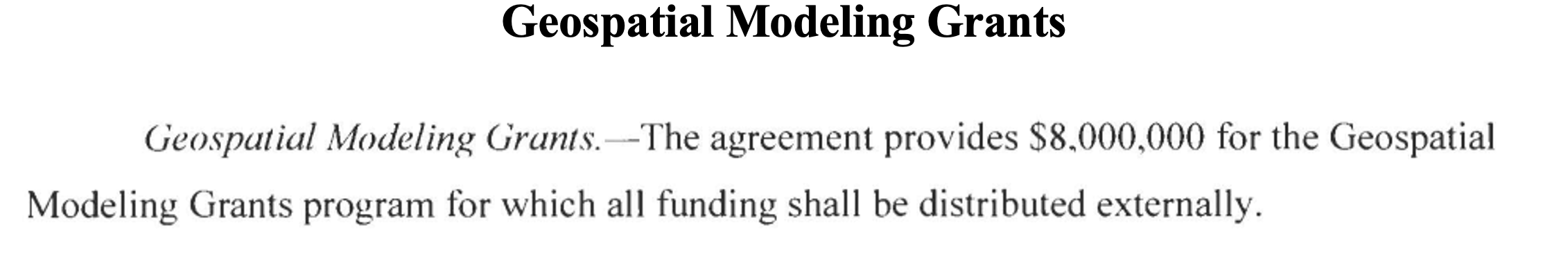
    The geospatial modeling grant was included in the 2023 Omnibus Appropriations Bill. The agreement provides $8,000,000 for the program and states that all funding shall be distributed externally. Hopefully, the same amount or more will be in FY 24 appropriations. Additional information about NOAA’s appropriations can be found in the 2023 Omnibus Appropriation Bill under the explanatory statement for Commerce, Justice, Science and related agencies. The bill can be found here. To find the language in the bill click here, then search the document for “geospatial.” See the image below for the language in the bill.

    Image: Senate.gov website
    Image: Senate.gov website

    For those that are interested in the appropriation process, the image below provides a list of the senators that work on these agencies’ appropriations. If you are interested in learning more about the appropriation process and the geospatial modeling grants, contact your senator. The more congressional representatives know about the geodesy crisis — which includes the lack of trained geodesist as well as surveyors — the sooner they will support funds to help correct the problem. Click here for a list of senators on the Commerce, Justice, Science and Related Agencies Appropriation Committee.

    Advancing geodesy with conferences

    Another activity that promotes the advancement of geodesy and surveying are national and international surveying and mapping conferences. Before the American Congress on Surveying and Mapping (ACSM) disbanded, the four-member organization collaborated to convene annual surveying and mapping conferences in the United States. Topics like those presented at a FIG Working Week were presented at these conferences.

    Since these ACSM conferences are no longer being held, I encourage users of geospatial data and GNSS technology to attend conferences like FIG Working Week 2023. I have participated in several FIG meetings and learned a lot from presentations as well as holding hallway meetings with experts from the international surveying and mapping community. In the March column, I highlighted that FIG Working Week 2023 is going to be held in Orlando, Florida, on May 28 – June 1. NGS will be presenting a full-day worth of content on NSRS modernization during the conference. I want to highlight some presentations that may be of interest to readers. Register for FIG Working Week 2023 here.

    The image below provides a list of NGS presentations with scheduled times. There will be a panel session in the beginning of the day to set the context for the day.

    Agenda of NGS DAY at FIG Meeting (Image: FIG website)
    Agenda of NGS DAY at FIG Meeting (Image: FIG website)

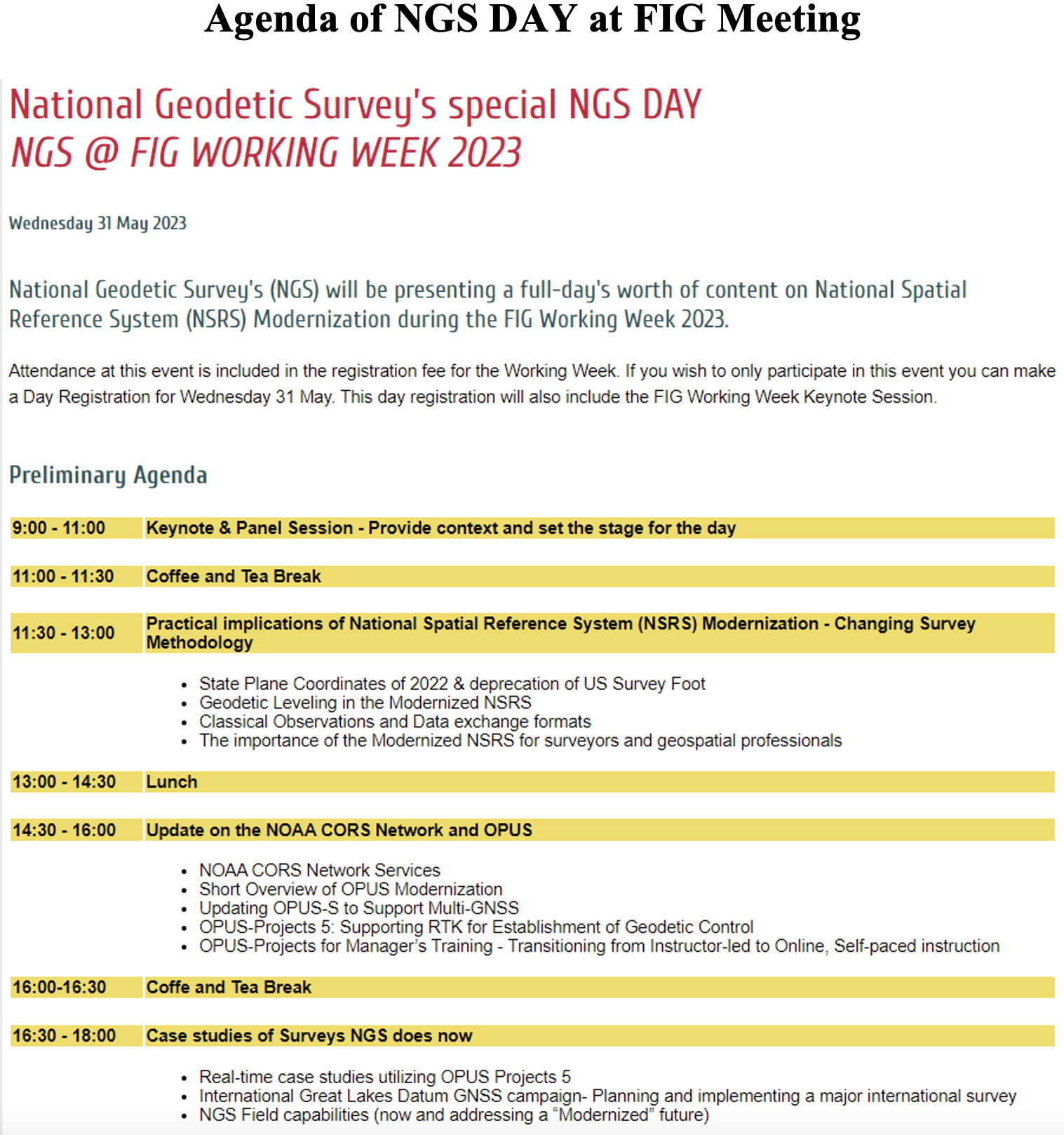
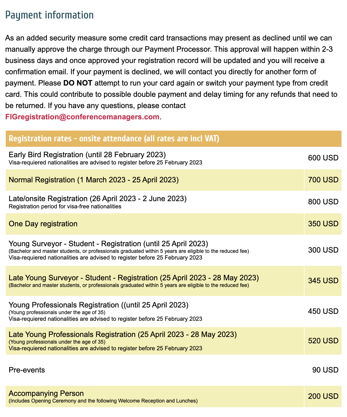
    As in most conferences there are several ways participants can register, one day to the entire conference. This is a great opportunity to have discussions with the leadership of the National Geodetic Survey and individuals working on the development of the new, modernized NSRS.

    Image: FIG website
    Image: FIG website

    There are a lot of presentations on various topics so, I would encourage readers to look through the entire agenda. FIG’s technical work is led by ten commissions. The August 2021 column provided information about the FIG commissions. See the list of commission below:

    Commission 1 – Professional Standards and Practice
    Commission 2 – Professional Education
    Commission 3 – Spatial Information Management
    Commission 4 – Hydrography
    Commission 5 – Positioning and Measurement
    Commission 6 – Engineering Surveys
    Commission 7 – Cadastre and Land Management
    Commission 8 – Spatial Planning and Development
    Commission 9 – Valuation and the Management of Real Estate
    Commission 10 – Construction Economics and Management

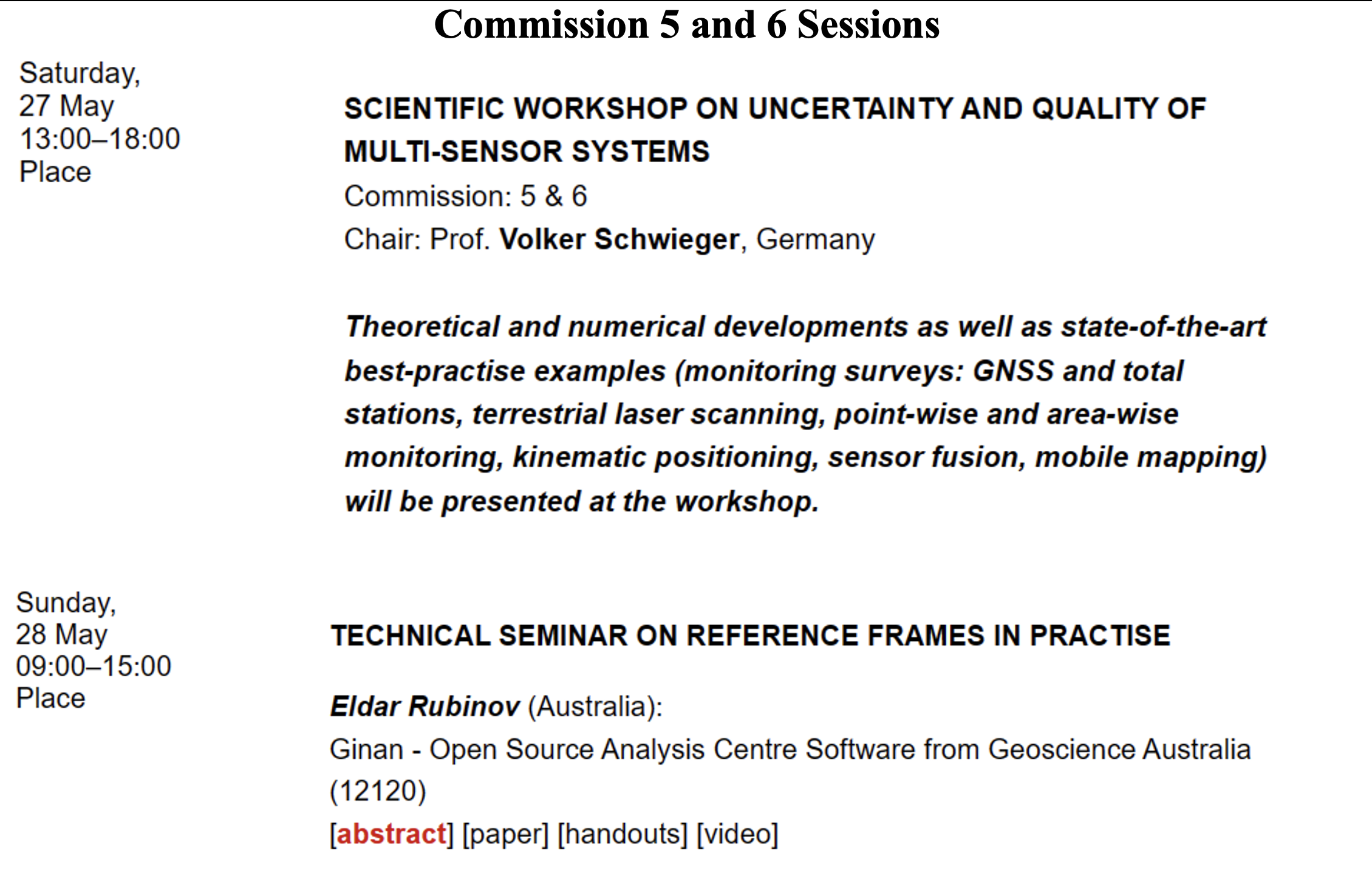
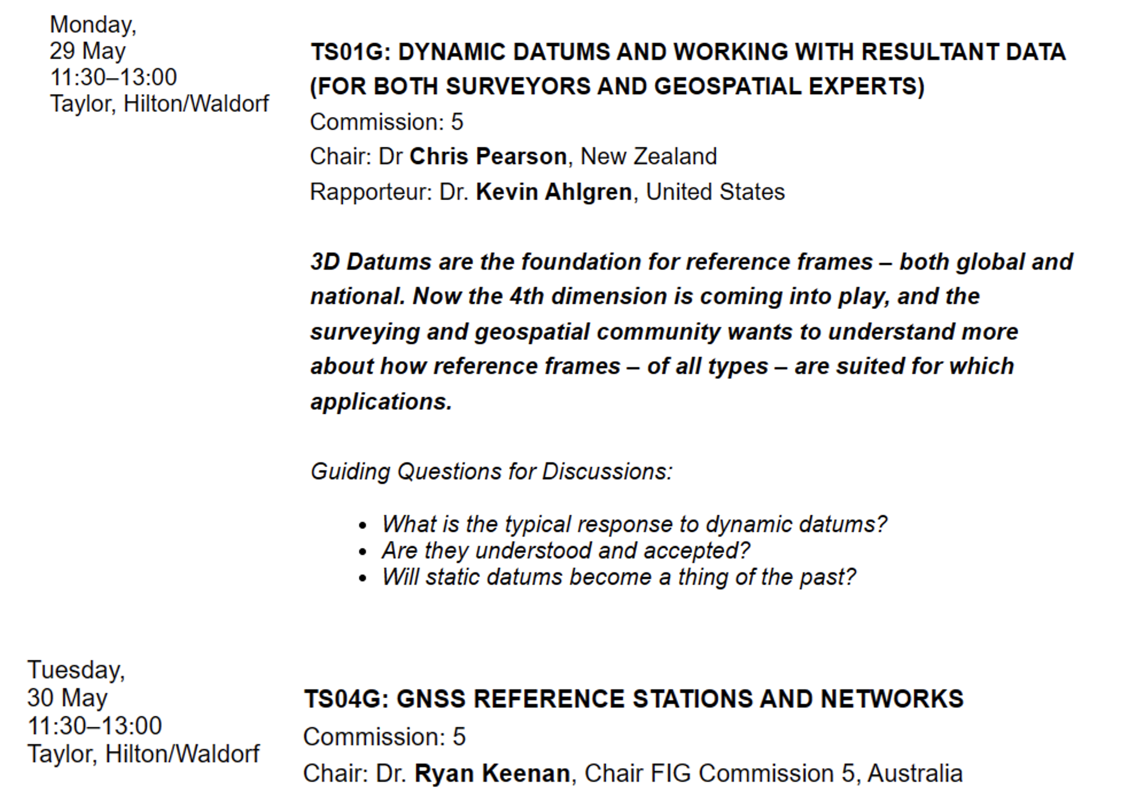
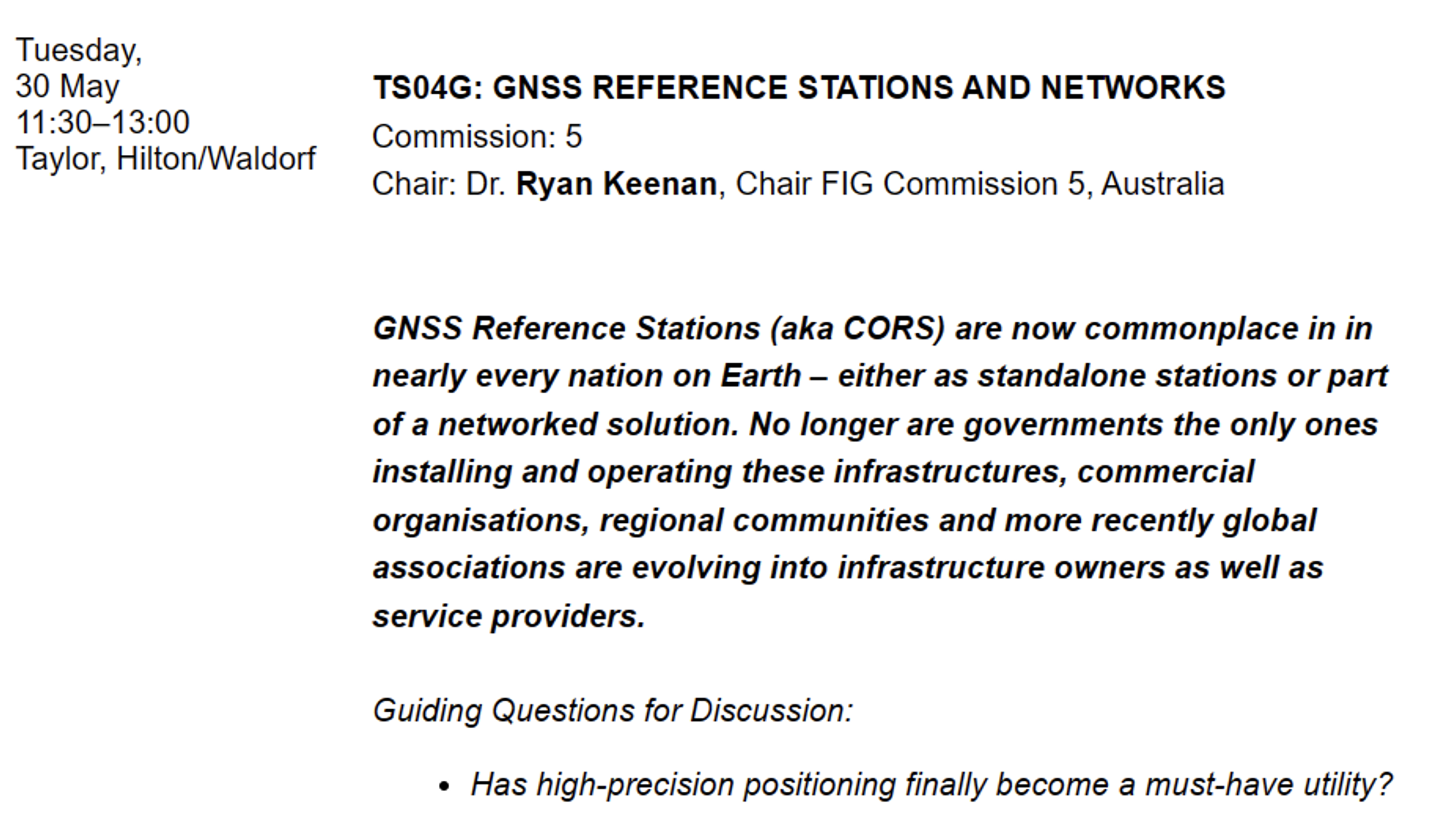
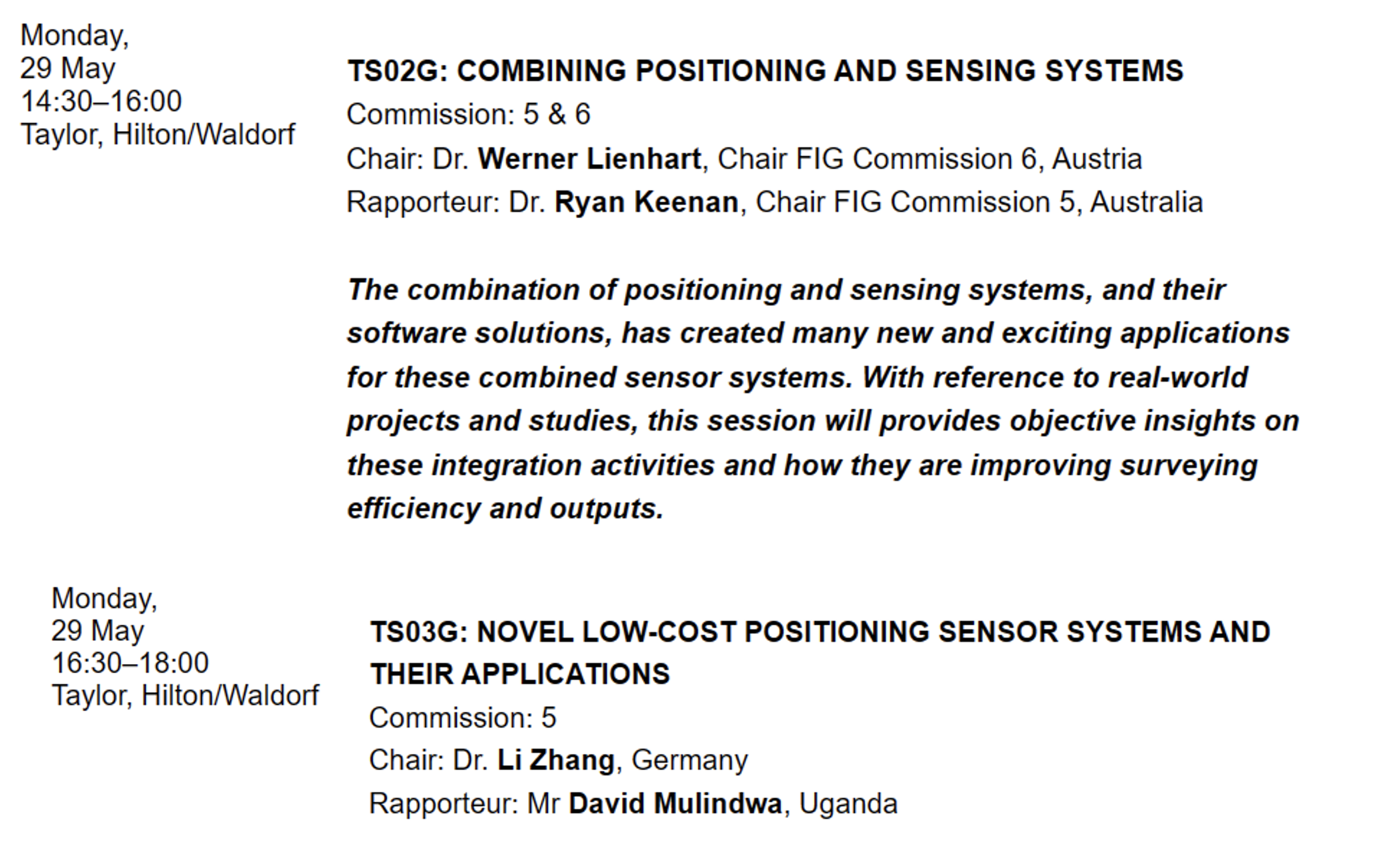
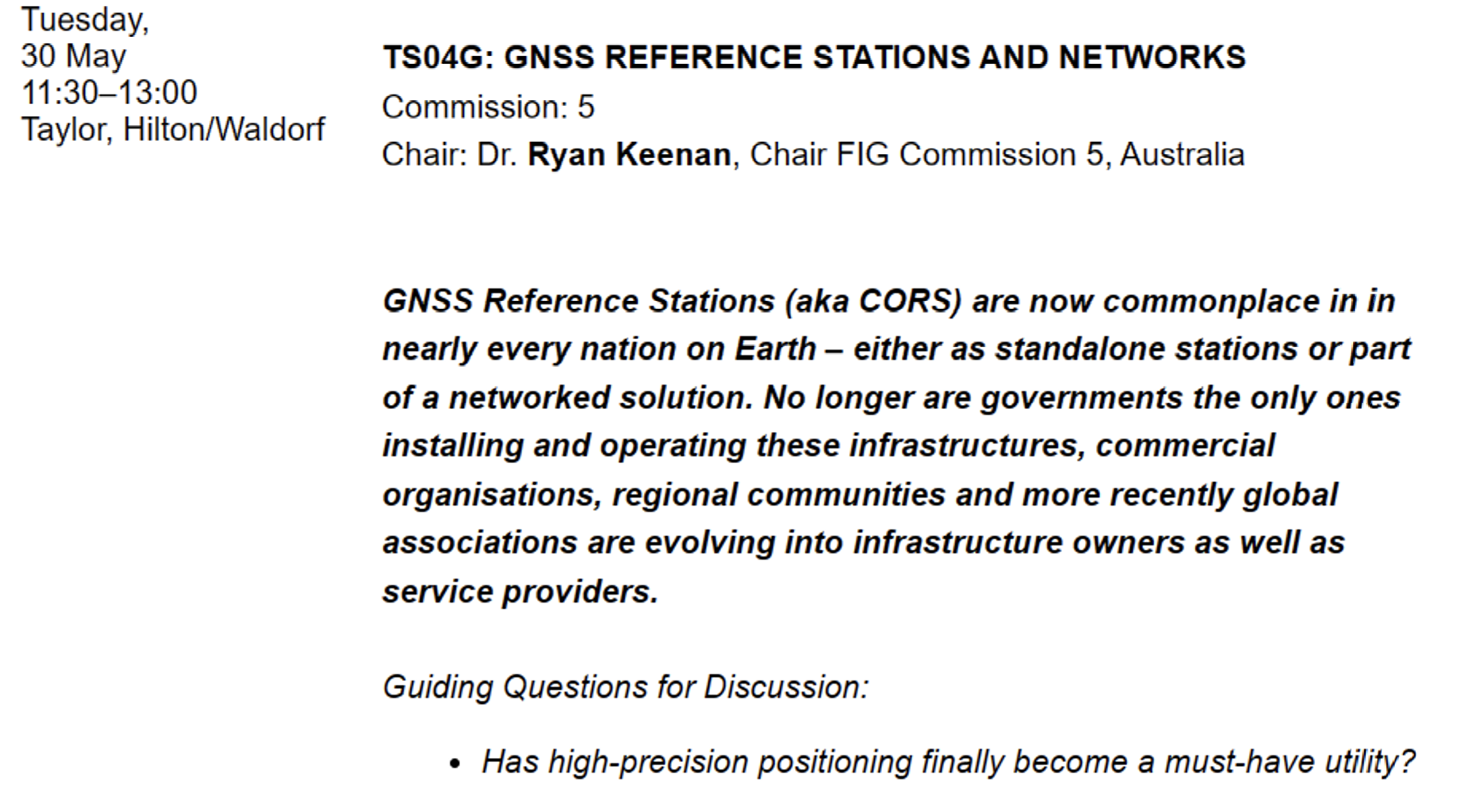
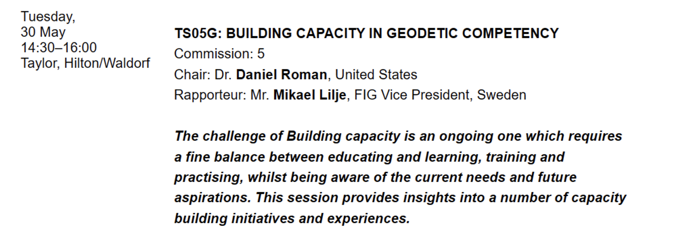
    The full technical program lists the topics by date and time. I highlighted sessions by commission 5 and 6 that I think would be interested to the surveying and mapping community. See the image below.

    Image: FIG website
    Image: FIG website
    Image: FIG website
    Image: FIG website
    Image: FIG website
    Image: FIG website
    Image: FIG website
    Image: FIG website
    Image: FIG website
    Image: FIG website
    Image: FIG website
    Image: FIG website
    Image: FIG website
    Image: FIG website

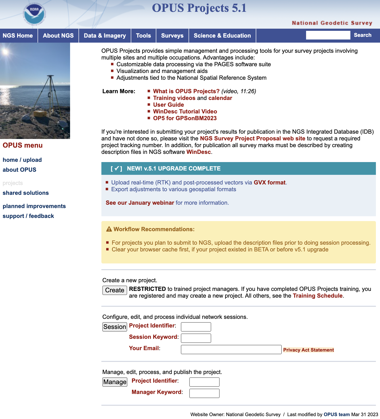
    Finally, I would like to highlight a NGS product that is now in production mode. That is, OPUS Project 5.1 is now a production product. *NGS did not make an official announcement about this change, but if you access OPUS Project the new version comes up. As described in the March column, OPUS Project 5.1 routine allows the use of RTN vectors and post-processed vectors from vender software.

    Clicking the “projects” icon on the OPUS page connects you to the latest version of OPUS Project 5.1. See image below. Please see the March column or NGS’ January webinar to learn more about OPUS Project 5.1.

    Image: NGS Website
    Image: NGS Website

    *Note: As of the writing of this column, March 29, it is still listed on the beta release section of NGS website. If you click on OPUS Project 5.1 in the Beta Release section, it will link to the production version of the routine.  

  • Leica lidar sensor improves deep water surveying

    Leica lidar sensor improves deep water surveying


    Image: Hexagon
    Image: Hexagon

    Leica Geosystems, part of Hexagon, has launched the Leica HawkEye-5, a new high-performance airborne bathymetric lidar solution for deep water surveying.

    Leica’s HawkEye-5 increases survey efficiency by up to 25% compared to previous generations. The technology expands the capabilities of the Leica Chiroptera-5 bathymetric lidar system, enhancing the productivity of applications such as nautical charting, environmental monitoring, and maritime surveillance in deep waters.

    The technology is designed to fit the Leica PAV100 gyro-stabilized mount, which isolates the sensor from unwanted aircraft movements — resulting in consistent data density and more efficient area coverage.

    The HawkEye-5 combined with the Chiroptera-5 features three lidar sensors, one four-band camera, and a QC camera to collect data from the seabed to land.

    The Lidar Survey Studio software suite provides full waveform analysis, automatic data classification and advanced turbid water enhancement to support multiple applications.

  • OxTS product now available with additional features

    OxTS product now available with additional features


    OxTS Georeferencer 2.5
    Image: OxTS

    OxTS has released its Georeferencer 2.5 with the anyNAV feature and eight lidar sensors from RoboSense. Georeferencer 2.5 featuring anyNAV software is suitable for survey applications.

    Users of Georeferencer 2.5 with anyNAV feature enabled can boresight payloads and georeference lidar data using the user’s navigation data. The anyNAV software enables lidar surveyors to create accurate pointclouds quickly.

    Georeferencer 2.5 now takes navigation data from third-party inertial navigation systems, which enables users to use that data to georeference raw lidar data from multiple sensor families. The resulting data can then be viewed in many pointcloud viewer software packages.

  • Inertial Labs launches Kernel-210/220

    Inertial Labs launches Kernel-210/220

    Inertial Labs has released its third generation of MEMS sensor-based inertial measurement units (IMU), MEMS KERNEL-210 and KERNEL-220.

    The KERNEL-210 and KERNEL-220 are compact, self-contained, strapdown, tactical-grade IMUs that measure linear accelerations and angular rates using their aligned and calibrated three-axis MEMS accelerometers and three-axis MEMS gyroscopes.

    Angular rates and accelerations are determined with low noise and good repeatability for both motionless and dynamic applications.

    The KERNEL-220 model utilizes accelerometers with ±40g and ±90g measurement ranges. The IMU is fully calibrated, temperature compensated and mathematically aligned to an orthogonal coordinate system. The KERNEL-220 contains gyroscopes with a bias in-run stability of less than 1 deg/hr and accelerometers with an in-run stability bias of 0.005 mg.

    Image: Inertial Labs
    Image: Inertial Labs
  • Inertial Labs launches IMU-P

    Inertial Labs launches IMU-P

    IMU-P.jpg
    Image: Inertial Labs

    Inertial Labs has launched its inertial measurement unit-P (IMU-P). It is an advanced MEMS sensors-based, compact, self-contained strapdown, industrial- and tactical-grade inertial measurement system and digital tilt sensor that measures linear accelerations, angular rates and pitch-and-roll with three-axis, high-grade MEMS accelerometers and three-axis, tactical-grade MEMS gyroscopes.

    Angular rates and accelerations are determined with high accuracy for both motionless and dynamic applications.

    Like Inertial Labs IMU-FI-200C, the IMU-P is fully calibrated, temperature compensated, and mathematically aligned to an orthogonal coordinate system. IMU-P demonstrates less than 1 deg/hr gyroscopes and 0.005 mg accelerometers bias inrun stability with low noise and high reliability.

    The IMU-P models collect data from an external source of GNSS to output full spectrum inertial navigation system data consisting of positions, attitude, velocity and time.

    The IMU-P is suitable for applications such as antenna and line of sight stabilization systems, GPS-aided INS, UAV & AUV/ROV navigation and control and more.

  • Why GNSS is the glue for construction

    Why GNSS is the glue for construction


    GNSS links the three steps in this example paving system. The mobile scanning system creates a 3D model that the grinding and paving equipment systems use. (Image: Topcon)
    GNSS links the three steps in this example paving system. The mobile scanning system creates a 3D model that the grinding and paving equipment systems use. (Image: Topcon)

    Even construction projects that involve separate pieces of heavy equipment can be tightly coupled, with GNSS as the “glue.” One example is Topcon’s SmoothRide paving system. The separate active steps of grinding and paving are working from a 3D model developed in a first step: precise mobile scanning. Each step constrains (horizontally) with GNSS, and vertically to the corresponding position in the model. In this example, the premium is on the quality of the scan.

    For the first step, an RD-M1 scanner, usually attached to a pickup truck, can scan at highway speeds. The positioning component is an integrated HiPer SR GNSS receiver and inertial measurement unit (IMU). The GNSS observations, IMU data, and velocity from a wheel encoder are post-processed (PPK) together, to provide a high-definition 3D model with very tight relative integrity.

    “A great lateral benefit of scanning in this manner is that it can be done quickly and also gives you a model of the area surrounding the road,” said Mark Larranaga, director, Intelligent Paving Business Development. “You get the terrain for drainage design, guardrails, signs, road furniture — everything you might need for good roadway design.”

    For base data for the post-processing, Larranaga said a GNSS base typically will be set up on the site, though if a permanent base from a network such as TopNet is nearby, that can be used.

    “The model is then created in MAGNET Collage software,” Larranaga said. “That produces the surface file. Once we get that created, we take it into a software called MAGNET Resurfacing. It is used to design for cross slope correction, or a smoothness factor, as well as material management  — the software will do all this automatically. The software empowers the customer to create a file for the machine that will maximize the potential of the end results, based on the project parameters. Thus, allowing the contractor to evaluate and learn about potential pitfalls and maximizing incentives.”

    The next step, using roadway surface grinding equipment, employs a two-antenna GNSS system (for position and heading). A sonic sensor is keyed to the corresponding elevations in the 3D model and informs the depth for which the grinder is set. The third step, paving, is quite similar: GNSS and a sonic sensor constrained by the precise 3D model. There are some implementations that add thermal cameras and look behind a paving machine to see whether certain target specifications are met in real time.

    Read more of this cover story, “Guide, Assist, Automate: Why GNSS remains a key element for most applications.”

  • Pilot project analyzes climate change for Caribbean nations 

    Pilot project analyzes climate change for Caribbean nations 


    Image: TommL/E+/Getty Images
    Image: TommL/E+/Getty Images

    NV5 Geospatial has forged a contract with the Caribbean Community Climate Change Center (CCCCC) to conduct aerial lidar and orthoimagery surveys across the Caribbean. The pilot project will provide advanced geospatial data to help the island nations understand natural and man-induced climate changes, develop programs to support resilience and sustainable development, and establish a foundation for future work.

    NV5 Geospatial will conduct topographic and topobathymetric lidar surveys, as well as orthoimagery, via a fixed-wing aircraft. Data collected will help CCCCC address the impact of climate variability and identify potentially hazardous impacts.

    The project will cover 10 sites spread across more than 3,000 km. The sites include areas in Suriname, Guyana, Tobago, Barbados, St. Vincent and the Grenadines, Saint Lucia, Antigua and Barbuda, St. Kitts and Nevis, Turks & Caicos and Belize.

    Other logistical considerations include the combination of microclimates inherent around tropical islands, highly variable weather conditions, cloud formations and jungles, some of which are in high relief areas or covering the entire area.

  • Inertial Labs releases multi-application IMU

    Inertial Labs releases multi-application IMU

    Inertial Labs has released its IMU-FI-200C, a compact, self-contained strapdown, advanced tactical-grade inertial measurement unit (IMU) device. The IMU-FI-200C measures linear accelerations and angular rates with its three-axis, tactical-grade, closed loop, fiber-optic gyroscopes and three-axis, high-precision MEMS accelerometers in motionless and high dynamic applications.

    The IMU-FI-200C is fully calibrated, temperature compensated and aligned to an orthogonal coordinate system. It contains more than 0.5 deg/hr gyroscopes and less than 2 mg bias repeatability over operational range accelerometers with low noise and high reliability.

    Continuous built-in test, configurable communications protocols, electromagnetic interference protection, and flexible input power requirements make the IMU-FI-200C suitable for a wide range of integrated system applications.

    Image: Inertial Labs
    Image: Inertial Labs
  • ComNav introduces rod-less GNSS receiver for surveying

    ComNav introduces rod-less GNSS receiver for surveying

    On Dec. 20, ComNav Technology launched its Venus Laser RTK, a GNSS receiver with a millimeter-level laser that enables rod-less surveying. This product is a part of ComNav’s Universe Series of GNSS receivers.

    Photo:
    Image: ComNav

    Venus Laser RTK comes with an inertial measurement unit (IMU), which can be used in its traditional mode, with a range pole or in laser mode, which does not require a range pole, enabling GNSS surveying beyond typical limitations. In traditional mode, it has tilt compensation up to 60 degrees with an accuracy of 2.5 cm; in laser mode, it has the same tilt compensation but an accuracy of 5.5 cm.

    This GNSS receiver is powered by a SinoGNSS K8 high-precision module, capable of up to 1,590 channels. It can survey using GPS, BDS-2, BDS-3, GLONASS, Galileo, QZSS, and SBAS constellations.

    Other features include Bluetooth connectivity, more than 20 hours of battery life, and the fact that it is dust and waterproof. Venus Laser RTK can also withstand harsh environments and is designed to survive more than a two-meter drop.

  • Aligning bricks and models

    Aligning bricks and models

    (Image: Eos Positioning Systems)
    (Image: Eos Positioning Systems)

    Surveying is both an ancient profession and one of today’s most technologically advanced. Surveyors are among the first on the site of a new construction project, staking out its corners and boundaries, and mapping elevation contours, as well as among the last, surveying the project “as built.” This is particularly important for features that will no longer be visible once the project is complete, such as underground utilities.

    While many surveyors work in quiet, uncrowded environments — such as surveying the boundaries of farm fields — those who work on large construction projects operate among the hustle and bustle of bricklayers, carpenters, electricians, plumbers and other tradespeople, as well as cranes, backhoes and other heavy machines. This chaotic environment means that in addition to accuracy and efficiency, surveyors also are concerned with safety.

    In the following cover story, a Minnesota-based construction company describes a new system it developed for surveying and mapping underground utilities. Also, professional surveyor Gavin Schrock discusses the benefits of a flexible approach to GNSS rover accuracy and of adding scanning capabilities to robotic total stations.

    Read the three parts of this cover story: 

    1. Minnesota company develops new system for mapping underground utilities new pipes
    2. Review benefits of GNSS rover accuracy
    3. Robotic total stations add scanning capabilities
  • Robotic total stations add scanning capabilities

    Robotic total stations add scanning capabilities

    A unique workflow enabled by scanning robotic total stations is the simultaneous operation, with the same data controller and software, of a GNSS rover while scanning and imaging are being performed. Pictured: a Trimble SX12 and R12i GNSS. (Image: Gavin Schrock)
    A unique workflow enabled by scanning robotic total stations is the simultaneous operation, with the same data controller and software, of a GNSS rover while scanning and imaging are being performed. Pictured: a Trimble SX12 and R12i GNSS. (Image: Gavin Schrock)

    This is part III of our III part cover story. Catch up on part I, Minnesota company develops new system for mapping underground utilities and part II, Review benefits of GNSS rover accuracy.


    Scanning capabilities, in one form or another, have been added to models of robotic total station (RTS) since 2007 — for instance, on the Trimble VX. Such capabilities were limited to a pattern of individual shots, as the RTS would “nod.” While not designed to compete with traditional scanners, even such painfully slow “pseudo-scanning” capabilities demonstrate the value of new options for capturing detailed features.

    It was not long before nearly all RTS offered limited (nodding scanning) capabilities, though at rates as slow as 15 shots per second. By 2013, the release of the Leica MS50 took the nodding scan to the next level, with a rate of up to 1,000 points per second, and then up to 30,000 in the subsequent MS60 model (which now also supports a tilting prism pole).

    The end of 2016 saw the release of Trimble’s SX10 (and SX12 more recently). This routed the laser through a pair of rotating prisms to capture a swath of points as it nodded. In 2019, Topcon took the approach of adding a piggy-backed compact conventional scanner to the top of an RTS: the GTL-1000 and GTL-1200 models.

    All these implementations were built upon high-quality RTS. Foremost, they can be operated as an RTS, with all the same integrated surveying capabilities as instruments with which surveyors were familiar, and in the same field software.

    This includes all the integrated GNSS workflows: resections, combining optical and GNSS captured points in the same survey, and adding a rover to the prism pole for track-on-GNSS methods. One huge advantage of scanning total stations is instant deliverables already fully registered, as adopters of these new systems quickly realized.

    Some initial users seemed skeptical of the relatively slow scan rates of these various models: 12 to 30 minutes for full-dome scans, and then a photo capture pass. Others, though, discovered that the time did not necessarily need to go to waste.

    First, it is not necessary to do a full-dome scan and image pass every time; it is sufficient to pre-select specific areas to scan and image.

    The real kicker is that while the RTS is scanning, it is possible to fire up the GNSS rover and capture points that the RTS cannot see, such as behind curbs, cars and vegetation. This is true especially now, with the advent of no-compensation tilt capabilities on nearly every new GNSS rover system.

    This can be done in the same project, using the same software and field controller. This struck this writer as one of the coolest lateral features of scanning total stations when he first tried out an SX10 in 2017.

    Considering the benefits scanning total stations deliver (especially with the integrated GNSS bonus), what has the reception been like among surveyors and other segments of the architecture, engineering and construction (AEC) community?

    “As an industry, we’re getting better at tying solutions and workflow elements together, and not seeing them, or treating them, as individual functions or pieces of hardware,” said Derek Shanks, director of Geospatial Optical Product Management for Trimble. “We bring the system aspect, a case of using the best tool, using the strengths of each tool to their fullest.”

    Accoring to multiple manufacturers, sales numbers indicate that the adoption of scanning total stations for AEC applications — and not just surveying — has exceeded expectations.

  • Review benefits of GNSS rover accuracy

    Review benefits of GNSS rover accuracy

    Douglas County Public Works needed a GNSS rover to support its UAS operations. The pay-as-you-go option was appealing as they only needed high-precision a few times per month. (Image: Jason Schilling)
    Douglas County Public Works needed a GNSS rover to support its UAS operations. The pay-as-you-go option was appealing as they only needed high-precision a few times per month. (Image: Jason Schilling)

    This is part II of our III part feature story. Check out part I, Minnesota company develops new system for mapping underground utilities and part III, Robotic total stations add scanning capabilities.


    High precision GNSS rovers play a vital role in a broad variety of field surveying and mapping applications. Different users have different value propositions in mind when choosing field hardware and software: expected precision, sources of corrections, configurations for specific workflows, and, of course, cost. Weighing these many considerations, GNSS manufacturers have come up with portfolios of multiple models to fill these varied needs.

    That said, GNSS manufacturer Bad Elf took a different approach when it designed its flagship rover, the Bad Elf Flex. The Flex is designed to meet the cost-precision-workflow needs of everyone, from asset mappers to surveyors. (Hence the name “Flex.”) To inform the design of the Flex, Bad Elf listened to field users who wished for a scalable solution in a single rover, rather than having to buy multiple different models, and without breaking the bank.

    Options for the Infrequent User

    “I had one of the little Bad Elf GNSS surveyor handhelds for many years,” said Jason Schilling, wildlife biologist with Douglas County Public Utility District in central Washington State. “That worked great for rough mapping, between a foot and a meter of precision, and I could connect it via Bluetooth to mapping software on my mobile.”

    But this all changed when Schilling began an unmanned aerial system (UAS) program for the utility several years ago.

    “I really needed survey-level precision for ground control points to geolocate the images from the UAS,” said Schilling.

    He was aware of the high cost of centimeter-precision-capable surveying rovers and it was too big of an investment, considering that he only did UAS mapping a few times a month. As an existing Bad Elf customer on the company mailing list, Schilling learned about the new Flex rover, which offered multiple options, and he found one that seemed quite enticing for the needs of his utility.

    Schilling purchased a Flex Standard bundle at a low base price, about $3,000, with the pay-as-you-go plan for high precision. In the standard configuration, the Flex is capable of autonomous positioning (1–5 m), and mapping grade (sub-meter precisions) via free satellite-based augmentation services (SBAS), such as WAAS. But when the user activates a pre-purchased “token,” the full centimeter-precision capability, using external corrections, is enabled.

    “On the day of a UAS survey, we turn it on, activate a token from our account, and then we have 24 hours of high precision,” Schilling said. “It costs us $25 per day.”

    For two to three UAS surveys a month, this works out to far less over many years than the cost of buying a typical surveying rover.

    Correction Sources

    For real-time kinematic (RTK) corrections, Schilling connects via NTRIP to the statewide cooperative real-time network (RTN); sometimes in a network RTK mode (such as VRS) or single-base RTK to a nearby reference station on the same network. The Flex accommodates NTRIP connections to RTN or IP-enabled reference stations, but Bad Elf has added even more flexibility for corrections.

    In some scenarios there is no access to an RTN or no cell service (needed for NTRIP access). One option in these cases is to add a second Flex, set it up as an RTK base, and connect the base and rover via radios that Bad Elf offers.

    Bad Elf has added other options for corrections: the Bad Elf RTK service taps into a nationwide real-time network operated by Point One Navigation. This is accessible via NTRIP in the same manner as regional, state or local RTN, and is offered for a monthly fee. In addition, for situations where there is no RTN or cell service, a global precise point positioning (PPP) service (Atlas) can be enabled on the Flex.

    PPP differs from RTK/RTN in that it does not need the dense arrays of reference stations, or cell service to access. Instead, PPP derives very precise clock and orbit data from a global array of tracking stations and delivers this to the Flex via geostationary satellites. After a short convergence time, PPP from the Atlas service will yield 5 –10 cm precision over most of the globe.

    The Full Boat

    full configuration. Brian Cortese works for the City of Ellensburg, where he uses the FLEX Extreme Bundle for multiple field applications. (Image: Brian Cortese)
    Full Configuration. Brian Cortese works for the City of Ellensburg, where he uses the FLEX Extreme Bundle for multiple field applications. (Image: Brian Cortese)

    The City of Ellensburg, a college town and farming community in central Washington State, chose the Flex Extreme bundle for about $6,000 — the “full boat” configuration. The Extreme bundle enables all the add-on services all the time, eliminating the need for tokens. In their case, the frequency of use made the higher initial investment worthwhile.

    “We have big plans for our rovers,” said Brian Cortese, Engineering Tech/Inspector for the City of Ellensburg Public Works & Utilities.

    Ellensburg is a vibrant town that is attracting a lot of new development and it is being proactive in surveying and mapping assets as they are added or replaced.

    “We’re recording manholes and valves, sewer systems, storm water systems, irrigation, hydrants — everything that gets built in the city gets as-built surveyed,” Cortese said. “Precise, real-time positioning, it’s been a benefit to us already. We can go out before they work on the subgrade for new developments and take measurements, and then when they finish the subgrade and pave it, we can go back and locate those exact positions.”

    Ellensburg uses corrections from the statewide cooperative RTN. In fact, one of the RTN reference stations —also part of the NOAA National CORS Network — is right in the center of town atop the science building of Central Washington University. While the city does a wide variety of surveying and mapping, with the Flex and RTN corrections surveyors get the same centimeter-precision for everything they measure in the field.

    “We’ve done design projects with it,” Cortese said. “For instance, we recently took measurements in an area of downtown for a proposal by recording positions and elevations to develop a new park and entertainment area for the community. We are also marking Americans with Disabilities Act (ADA) ramps to meet federal specs out in the field — it’s been really handy for so many things.”

    Survey-Grade Rover

    To serve the full range of precision needs, the Flex had to be designed as a survey-grade rover. It has a full-constellation GNSS and RTK engine: GPS, GLONASS, Galileo, BeiDou, and support for other regional constellations. With more satellites in view, it can perform in sky-view-challenged locations, such as around buildings and under tree canopy.

    “Ellensburg is on the Tree City, USA list; our streets are very well lined with a variety of trees, which is also where a lot of our utilities are and development is going on,” Cortese said. “We have been able to get good precisions in and around those trees. Actually, someone on our staff is taking an inventory of the trees with the Flex and loading the data directly into ArcGIS.”

    Even in the more rural areas of Grant County that enjoy a lot of open sky, Schilling said, some areas planned for mapping are along upper tributaries and in the hills with a lot of tree coverage. He said the Flex has performed well in those areas.

    Choices

    The Flex offers these options and combinations:

    • Flex Extreme. Full survey-grade rover that can use a variety of correction types.
    • Base-Rover RTK. Two Flex Extreme units connected via radio.
    • External RTN/RTK corrections via NTRIP.
    • Bad Elf RTK Service. Single-tap access to a nationwide RTK corrections service.
    • PPP service. Atlas PPP corrections via L-band geostationary satellites.
    • Flex Standard. Pay-as-you-go high-precision-enabled service using tokens.
    • Static Logging. Observation file logging for post-processing (supported by Flex Extreme).
    • Compatibility with multiple field-mapping software applications.

    While many modern GNSS rover systems support one or more options similar to those listed above, Bad Elf’s Flex supports all of them, making it capable of a wide variety of applications.