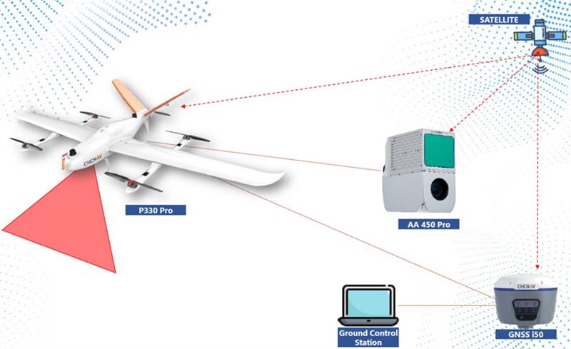
CHC Navigation’s mobile mapping solutions, the P330 Pro vertical take-off and landing unmanned autonomous vehicle (VTOL UAV) and the AlphaAir 450 lidar, are being used for mining exploration in Indonesia. The solutions help with effective data collection to measure the volume of an open-pit mine.
The P330 Pro UAV and the AlphaAir 450 provide an effective surveying solution, which is critical to the life cycle of mining projects. During this operation, the solutions covered more than 5 km² per mission, with an error of less than 5 cm. Accurate lidar in vegetated areas enabled surveying of the ground surface, including structures missed by other surveys due to dense vegetation.
A CHC Navigation i50 GNSS receiver and processing software provided with the AlphaAir 450 were deployed during the operation.
The P330 Pro UAV enables small- and large-scale aerial surveying. It comes with a portable ground control station for remote control and communication between the UAV and its operator. The UAV is designed for vertical takeoff and landing, making it convenient to operate and transport.
The AlphaAir 450 is a lightweight and rugged system, which integrates lidar with an industrial-grade professional 26 MP camera and an inertial navigation system for data collection.
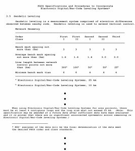
My previous column provided an update on the current set of published orthometric heights in the southeast Texas region and rules by the National Geodetic Survey (NGS) for estimating and publishing GNSS-derived orthometric heights using OPUS Projects. It also highlighted my personal crusade, that is the United States geodesy crisis. The Geodesy Crisis white paper can be downloaded from the American Association for Geodetic Surveyingwebsite.
This column focuses on potential errors in orthometric heights using a digital barcode leveling system with multi-piece leveling rods. Every business makes decisions based on expenses and ultimately on the profit margin. That said, making a business decision that results in a bad technical outcome may lead to issues that cost the company more than expected.
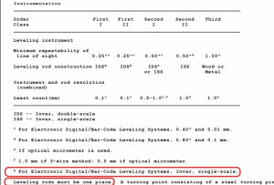
I have been involved with establishing orthometric heights, both leveling-derived heights and GNSS-derived heights, for most of my career. On a personal note, the digital bar code leveling system is important to me because I was the lead author of the document by the Federal Geodetic Control Subcommittee (FGCS) to incorporate the digital barcode leveling systems “Specifications and Procedures to Incorporate Electronic/Digital Barcode Leveling Systems (2004).” Recently, a colleague brought to my attention that many surveyors are using the digital barcode leveling system (which wasn’t a surprise to me), but they are not using the one-piece, single-scale, invar rod. They are using the multi-piece rods, either fiberglass or wooden. Surveyors can use any type of instrument to perform their project, but it will not meet the Federal Geodetic Control Subcommittee specification and procedures for leveling unless they use a one-piece leveling staff. This not a new requirement; it has been a requirement since the first publication of the FGCS specifications and procedures. Surveyors have always requested to use multi-piece rods but the potential errors associated with them were considered too large to be incorporated into the specifications and procedures to meet first-, second-, or third-order U.S. federal accuracy standards.
Excerpt from FGCS Specifications and Procedures (Image:FGDC)Excerpt from FGCS Specifications and Procedures (Image:FGDC)
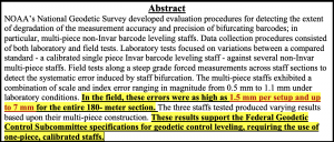
In 2018, NGS documented a study to evaluate the use of multi-piece rods using the digital barcode leveling system. I first saw a draft of this report in 2011 and forgot that it existed. A colleague of mine recently provided me with the 2018 report. In my opinion, anyone who uses the digital barcode system and multi-piece rods should read this report and, of course, the rest of this column.
NOAA Technical Memorandum NOS NGS 75. (Image: NGS)
The image below provides the important summaries of the tests. I highlighted the statement “In the field, these errors were as high as 1.5 mm per setup and up to 7 mm for the entire 180-meter section.” In my opinion, an error of 7 mm in a 180-meter section is too large for any order and class of leveling. Also, the results of the study support the current FGCS specifications and procedures requirement of the use of one-piece, calibrated rods.
Image: NGS
The 2018 report states that multi-piece level staffs are popular among the surveying community because of their ability to break down into an easily transportable unit and they are relatively inexpensive and readily available. They may also be extended to reduce the number of leveling setups required over sloping terrain. This makes good business sense but surveyors should not make technical decisions based solely on business costs. That said, the FGCS “Specifications and Procedures to Incorporate Electronic/Digital Barcode Leveling Systems (2004)” prohibit the use of multi-piece rods for any order/class of leveling based on technical decisions, not on business expenses. To evaluate the multi-piece barcode rods, NGS developed and implemented laboratory and field tests designed to detect and quantify possible loss of precision in multi-piece leveling staffs. All their tests were conducted at the NGS Testing & Training Center located in Woodford, Virginia, in December 2011. The report was published in 2018.
The report did note that only a small sampling of instrumentation, three multi-piece leveling staffs comprising two separate models from two separate manufacturers, were included in the NGS study. Therefore, the results found within the report evaluate the accuracy and precision of the specific staffs tested. As the report states: “The tests are qualitative in nature with respect to bifurcation and non-Invar construction. Similar results are expected for similarly designed level staffs; nevertheless, the results should not be considered precisely valid for all types or models of multi-piece leveling staffs.”
Users should download the document and read it but I’ll highlight a few results. First, the report made the following statements about the plumbing of the rods:
“With the Leica GKNL4M level staff carefully plumbed, the section directly above the bottom section housing the level vial was visually slightly out of plumb. No correction was made for this effect in the lab or field tests. No measurements were made to the top third section of this level staff during this evaluation.”
“With the Trimble LD23 level staff carefully plumbed, the sections directly above and below the middle section housing the level vial was visually bowed and slightly out of plumb. No correction was made for this effect in the lab or field tests.”
Obviously, having a correctly plumbed rod is extremely important.
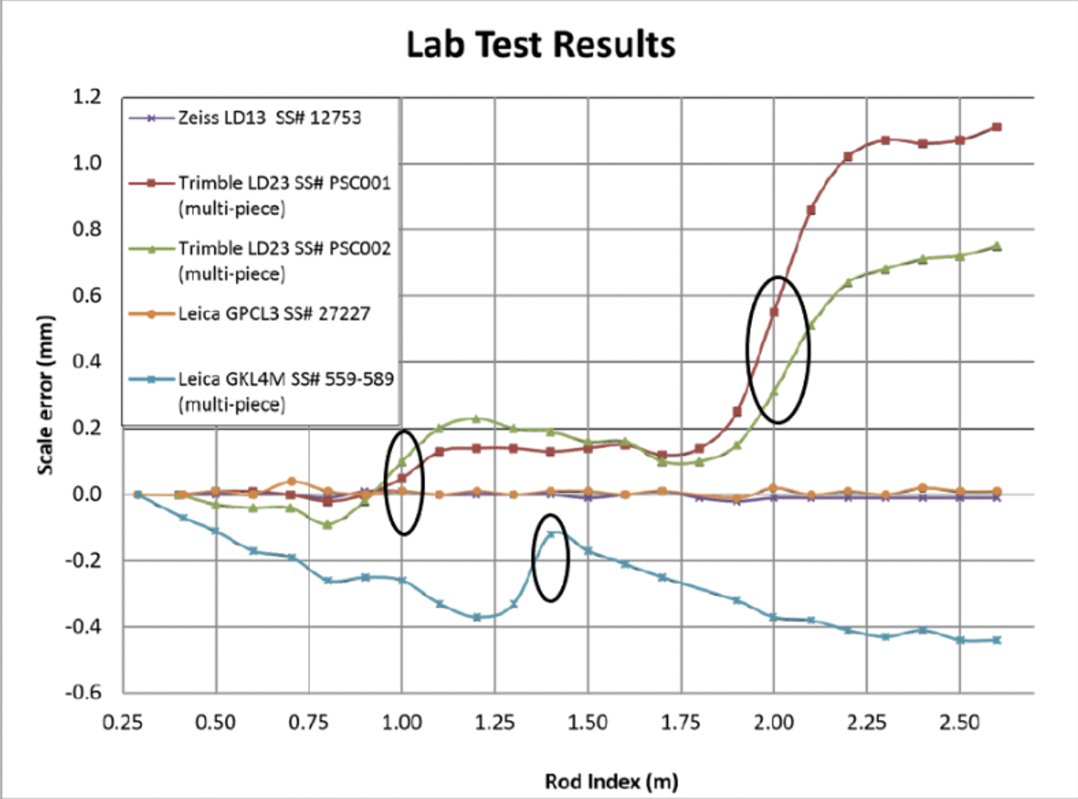
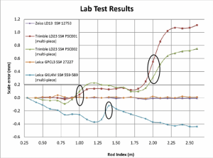
To estimate the potential scale error in a controlled environment, NGS performed a special test where they set up the level instrument 5 m from the leveling rods inside their building and made a measurement every decimeter on each rod. To perform this, the level instrument was moved upward one-decimeter after each measurement and the measurement was repeated. Figure 9 from the 2018 report depicts the results of the process. The first thing to notice is that the two calibrated, invar rods indicate very small errors. The other thing to notice is that there is a change in scale error at the section breaks of the multi-piece staffs. I highlighted the section breaks in the image below. The plots in Figure 9 indicate that the upper section of the rod is different from the lower section. This may result in a large error when going up (or down) an incline; that is, when leveling up an incline the upper section of a rod would be read in the back-sight reading and the lower section of a rod would be read in the foresight reading. The opposite would occur going down the incline.
Figure 9 from NGS 2018 report. (Image:NGS)
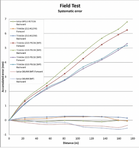
NGS also performed a small field test. The height difference was only 10 m over about 180 m distance. Figure 15 from the report provides the results of their field test. Some of the rods showed an error of almost 7 mm in the 180-meter section. Obviously, this is a significant error over such a short leveling distance, especially since it appears to be systematic. The report made a note about the systematic error; it noted that the height differences between the forward and backward runs were similar, but they were different from the standard. In other words, the forward and backward runs may meet a FGCS section misclosure but the mean difference would still have the accumulated systematic error. This means that following double-run procedures will not account for the systematic error. As a side note, according to FGCS specifications and guidelines, for establishing a height of a new bench mark, double-run procedures must be used. Single-run methods can be used to re-level existing work provided the new work meets the allowable section misclosure.
Figure 15 from NGS 2018 Report. (Image:NGS)
As stated in the 2018 report, errors as large as 6.8 mm over a 180-meter sloping section were due to using the multi-piece leveling rods. This is unacceptable for meeting FGDC specifications and procedures for leveling surveys.
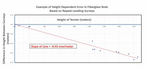
The NGS report was based on a small sample and over a very small project area. It provides a compelling argument for requiring one-piece leveling rods. Now, for a real-world example that supports the results of NGS’s study. I received a report where the results of repeat leveling surveys using the multi-piece fiberglass rods over the same basic route indicated a large systematic height error. The figure below provides the difference in heights between the two surveys. As indicated in the figure, the data indicates a height dependent error of -0.43 mm/meter between the two surveys. In this example, the difference approaches 200 mm. Clearly this type of systematic error needs to be accounted for when multi-piece barcode rods are used in a survey.
Example of Height Dependent Error in Fiberglass Rods. (Image: Dave Zilkowski)
As previously stated in the conclusion of NGS’s 2018 report, “Calibration of these type survey instruments provides a means of quantifying these type error sources, thus providing a mechanism for ‘correcting’ for them during post processing of data sets.” If a company or agency created a calibration process similar to NGS’s test site, then surveyors could use the site to evaluate their multi-piece barcode rods. In my opinion, until users account for the index and scale error in multi-piece barcode leveling rods, they should not be used to perform leveling surveys to compute orthometric heights with any expected accuracy value.
Clearly, it is more cost effective to use multi-piece rods instead of single-piece invar rods because of the increase in expenses for the single-piece invar rods. However, making a business decision that results in a bad technical outcome could lead to lawsuits, professional liability issues, and/or additional expenses for having to resurvey projects. Enough said.
Movella, a leading provider of sensors and software, has launched a partnership with Fixposition, a manufacturer of precise positioning sensors. The partnership aims to develop and commercialize GNSS inertial navigation sensors and implement visual inertial odometry through new products.
In December 2022, Movella and Fixposition launched the first product from the partnership, the Xsens Vision Navigator. This product integrates position inputs from three high-accuracy sources including dual-antenna RTK GNSS receivers, an IMU incorporating a three-axis accelerometer, gyroscope and magnetometer and a visual inertial odometry system.
The Xsens Vision Navigator can optionally accept inputs from an external wheel speed sensor. The positioning sensor achieves centimeter-level accuracy when operating in GNSS mode with an RTK fix. When GNSS signals are not available, the product alone achieves an accuracy of 2% of travel distance, or 0.75% when supplemented by wheel speed.
Xsens Vision Navigator is suitable for outdoor positioning applications such as material handling equipment, commercial and specialist vehicles, last-mile delivery, inspection equipment and UAVs, agricultural equipment, mining equipment and utility robots.
Xsens Vision Navigator is available now from Movella or authorized distributors of Xsens products.
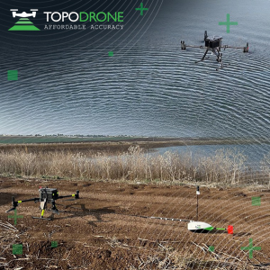
On Jan. 12, TOPODRONE used its synchronized lidar, airborne photogrammetry and bathymetric surveying methods to study a floating solar farm in Israel. This was completed upon request from the UAV service provider ERELIS, to help conduct a pilot project of reservoir surveying with a UAV for ETZ HADEKEL in northern Israel.
As the surface of the reservoir in Northern Israel is covered by solar panels, it is difficult to use standard methods of surveying from a boat. The goal of this study was to create 3D models, which can be used for high-precision assessments of sediment volumes, general monitoring of reservoir banks and visual monitoring.
Image: TOPODRONE
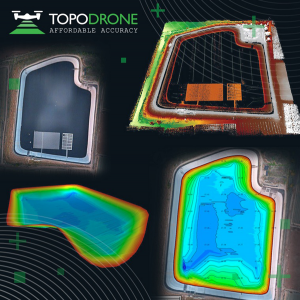
During this project, ERELIS performed two-stage UAV surveying to create the 3D model of the reservoir. In the first stage, aerial photogrammetry and lidar surveys were performed using a DJI M300 UAV. The UAV was equipped with the P61 TOPODRONE camera and a lidar high-resolution system to determine the location of obstacles. The lidar scanning provided accurate detection of cables in the water.
The second stage included an underwater bathymetric survey using the TOPODRONE AQUAMAPPER mounted to the DJI M300 UAV. The flight mission was planned and executed with the UgCS software by SPH Engineering.
All data collected from the study was processed by TOPODRONE Post Processing software. This generated a georeferenced orthophoto map, a 3D model of the relief and objects, a 3D model of the bottom of the reservoir and a model of contour lines and isobaths.
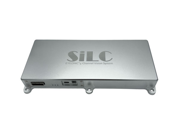
SiLC Technologies has launched the Eyeonic Vision System. This system is a frequency-modulated continuous wave lidar solution, which delivers high levels of vision perception to identify and avoid objects with low latency.
At the core of the Eyeonic Vision System is SiLC’s fully integrated silicon photonics chip. It provides more definition and precision than legacy lidar solutions, with roughly 10 milli-degree of angular resolution coupled with millimeter-level precision. These features enable this solution to measure the shape and distance of objects with high-precision and at a large distance.
The system combines the Eyeonic Vision Sensor and a digital processing solution based on a powerful field-programmable gate array. The flexible architecture enables synchronization of multiple vision sensors for unlimited points per second.
SiLC demonstrated the Eyeonic Vision System at CES 2023. It was named by the CES award committee as an honoree for the CES Innovation Award.
The compact, powerful, vision solution is suitable for autonomous vehicles, smart cameras, robotics and other advanced products. It is available now. Pricing varies depending on configuration.
On Jan. 6, ROCK Robotic, a geospatial company specializing in lidar-based data processing and high-definition mapping, announced the availability of ROCK Base, a triple frequency RTK base station. Additionally, ROCK Robotic has partnered with the Web3 GEODNET initiative to support critical applications in civil surveying, high-definition mapping, digital twin creation and more.
ROCK Base is a resilient, secure, full-constellation GNSS receiver, capable of tracking signals transmitted from GPS, GLONASS, Galileo, BeiDou, QZSS, and the IRNSS navigation satellite constellations. It includes 1,400 channels, survey-grade antennae, cables and antennae-mounting equipment required to set up a permanent continuously operating reference station location.
To make high-definition mapping more accessible and affordable, ROCK Robotic joined the Web3 GEODNET initiative, the largest decentralized GNSS reference network globally. Under the new partnership, ROCK Robotic customers will have access to the GEODNET base-station network to geo-reference ROCK Robotic’s 3D data products to millimeter-level absolute position accuracy, without setting up ground control points. Additionally, ROCK Base is pre-certified on the GEODNET network.
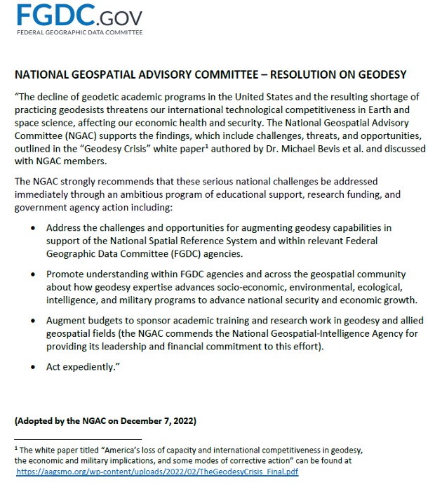
First, happy New Year to everyone. As a follow up to my November 2022 column on the geodesy crisis, I’d like to highlight that the National Geospatial Advisory Committee (NGAC) of the Federal Geographic Data Committee (FGDC) just adopted a resolution on the need for the federal government to understand and aggressively address the US geodesy crisis. See below. This is great news and, hopefully, the FGDC and others will follow up with discussions with other organizations such as the Office of Science and Technology Policy (OSTP) in the White House.
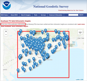
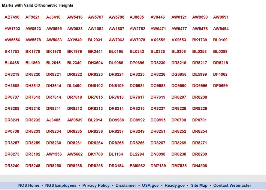
Now for this month’s column. Last year the National Geodetic Survey (NGS) started suppressing height information in Southeast Texas (see my April 2021 and June 2021 columns). See below for more information. Last year’s columns highlighted the potential effects of subsidence on published heights in the Houston, Texas, region which implied that most of the published heights, which are based on older surveys in the region, are not current or accurate. At the time of NGS’s announcement, only 28 marks with orthometric heights were published on NGS datasheets in southeast Texas. Click here for more information and see below.
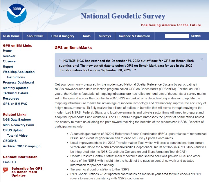
This column will provide an update on the following: the current set of published orthometric heights in the southeast Texas region based on recent GNSS surveys performed during 2021 and 2022, NGS’s rules for estimating and publishing GNSS-derived orthometric heights using OPUS Projects, and the status of NGS’s GPS on Benchmarks program.
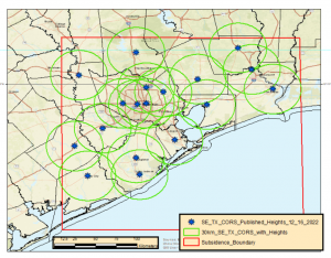
I always retrieve the latest published coordinates using NGS’s datasheet website routine. See the graphic below of the published NAVD 88 orthometric heights as of Nov. 20, 2022 (I used NGS’s monthly archive by State retrieval option). There are currently 147 marks with published orthometric heights within NGS’s definition of the southeast Texas zone of subsidence. From mid-October to early December of 2022, another GNSS project sponsored by the Harris-Galveston Subsidence District (HGSD) was performed in the region. In this project, 154 marks in the southeast Texas region were observed. The results of this project should be published and disseminated by NGS in the spring of this year.
Latest Published Heights in Southeast Texas. Image: Dave Zilkoski
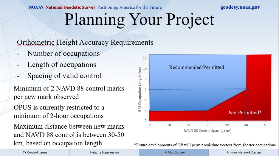
The current version of OPUS projects allows the user to estimate NAVD 88 orthometric heights, providing they adhere to NGS’s recommendations and procedures. A presentation titled “Heights Suppression in Southeast Texas” by Boris Kanazir, NGS, provides guidance on estimating NAVD 88 orthometric heights using OPUS projects.
See below for the requirements for number of occupations, duration of each session, and the spacing of marks with valid NAVD 88 published orthometric heights.
The requirements include:
a minimum of two NAVD 88 control marks per new mark observed
a mark must be observed twice on different days and at different times of the day
the maximum distance between new marks and NAVD 88 control is between 30-50 km, based on session duration
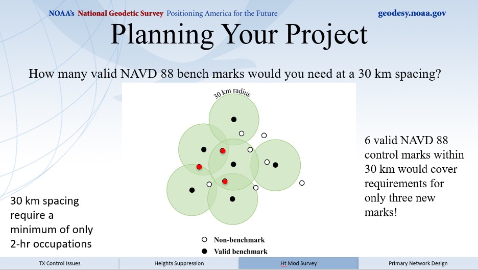
I like to think of this concept as drawing Venn diagrams around marks. See below for an example of the concept.
Venn Diagram. Image: Dave Zilkoski
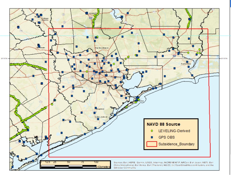
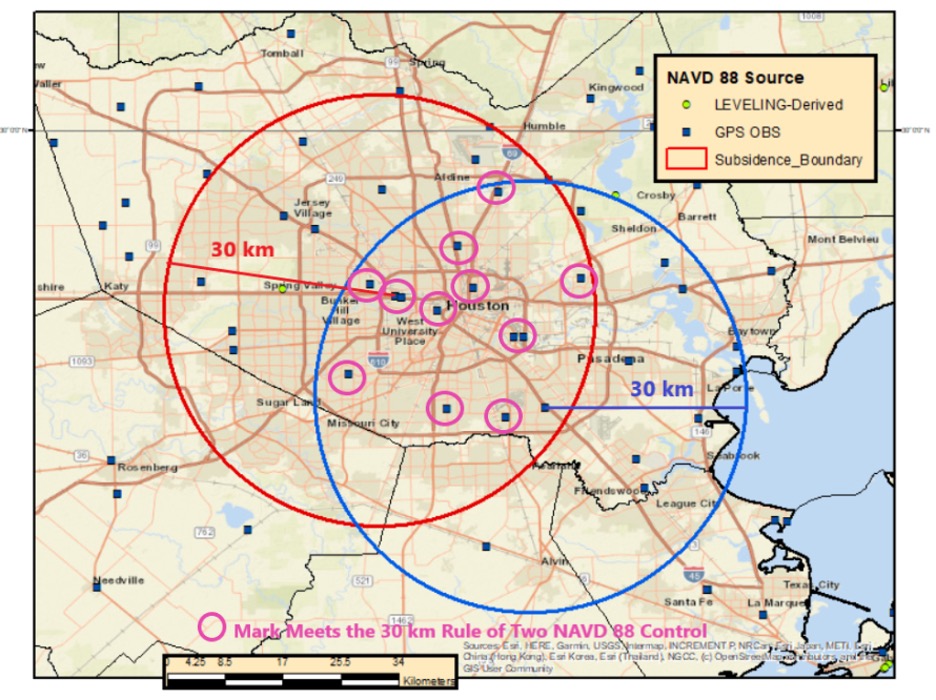
So, what does this mean in the real world? The map below demonstrates the concept in the Houston-Galveston, Texas, region. As shown, many of the 30 km circles overlap, indicating that in these overlapping areas there are two CORS with published NAVD 88 orthometric height. This means that a user can occupy a mark for two hours and use the data from two CORS as NAVD 88 control. Of course, the mark must be occupied twice for redundancy.
30 km Radius Circles around SE TX CORS with NAVD 88 Heights. Image: Dave Zilkoski
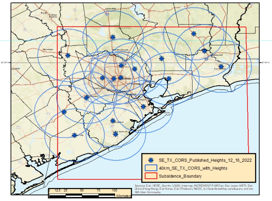
Increasing the radius to 40 km includes more overlapping areas. This means that the user would have more overlapping areas with two CORS that have published NAVD 88 orthometric heights, but the marks would have to be occupied twice for at least four hours each time.
Image: Dave Zilkoski
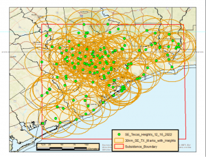
Now, when you apply a 30 km radius around the current 147 marks that have published NAVD 88 heights, most of the region has overlapping areas (see below). This means that the user could occupy two of the NAVD 88 marks along with any new marks for at least two hours.
30 km Radius Circle Around all 147 NAVD 88 Marks in SE TX. Image: Dave Zilkoski
The previous figure may seem confusing because of all the circles. In the example below, based on only two marks, 11 marks fall inside the overlapping sections of the two circles. They could be established using the two NAVD 88 control marks that were used to make the 30 km circles.
Example of Two 30 km Radius Circles. Image: Dave Zilkoski
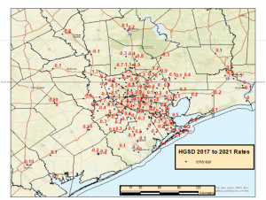
As depicted in my June 2021 column, the Houston-Galveston, Texas, region is subsiding. The map below provides the latest estimates of subsidence in Houston-Galveston, Texas, region based on a Harris-Galveston Subsidence District (HGSD) report “Determination of Groundwater Withdrawal and Subsidence in Harris and Galveston Counties – 2021“ published in 2022. Most of the rates are small, less than 0.5 cm/year, but some are greater than 1 cm/year. This means that some marks may have subsided around 5 cm in five years.
Estimate of subsidence in SE TX. Image: Dave Zilkoski
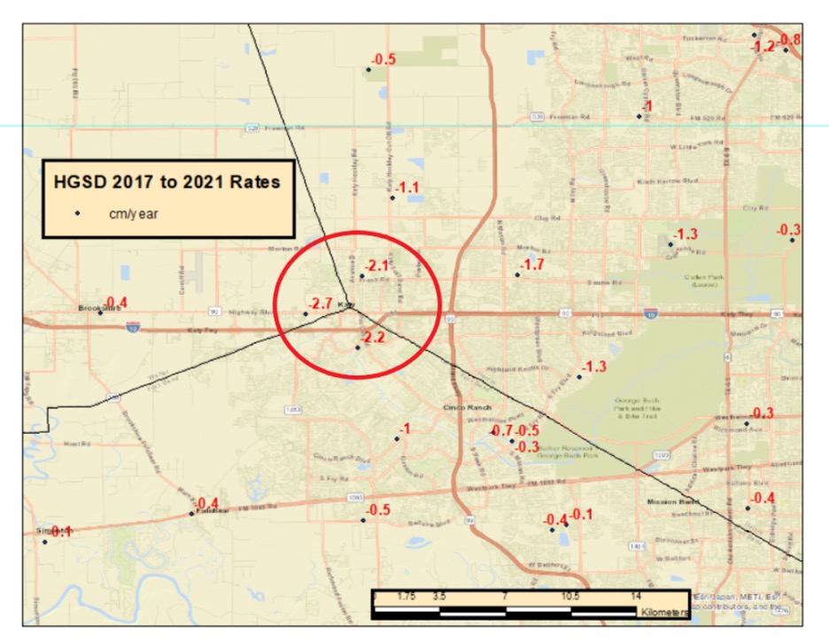
The surveying and mapping community has done a tremendous job of increasing the number of published heights in the Houston-Galveston, Texas, region (from 28 to 147). That said, the amount of movement in the Katy region is more than -2 cm/year (see box titled “Estimate of Subsidence in the Katy Area”). That means, the marks in this area may subside 10 cm in five years.
Estimate of subsidence in the Katy Area. Image: Dave Zilkoski
Heights that change 10 cm cannot be considered NAVD 88 control marks. NGS’s OPUS Projects User Guide states the following about superseding a mark’s coordinates:
“Users should review the newly adjusted coordinates on user marks to decide whether they recommend that the user mark be re-determined (re-published). Typically, this would happen if the coordinates have shifted by more than 2 centimeters horizontally or 4 cm vertically from the published coordinates marks.”
Therefore, these marks in the Katy region may not be valid NAVD 88 control marks in about two years. Even marks that are subsiding at 1 cm/year may not be valid NAVD 88 control marks in about four years.
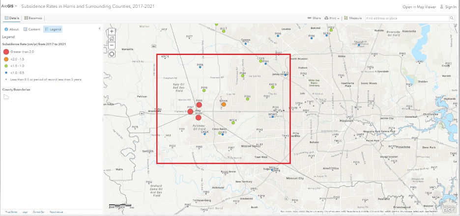
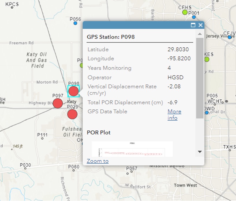
The community needs to maintain these marks to account for movement in the region. As previously stated, the Harris-Galveston Subsidence District (HGSD) has marks, denoted as PAMS, that are occupied continuously for a week several times throughout the year. These PAMS and the CORS in the area could be used to estimate crustal movement rates and maintain a set of valid, published heights in the region. See the boxes titled “ArcGIS Online HGSD Subsidence Rates” and “PAM 98 Subsidence Rate.” Additionally, the Texas Spatial Reference Center (TSRC) could provide the appropriate services to help maintain the published coordinates. The TSRC website states, “The technical mission of TSRC is to conduct basic and applied research contributing to NGS’s national Height Modernization program. TSRC is a repository for information used by researchers to develop improved understanding of elevation, geodetic and vertical datums in the state of Texas. The TSRC goal is to re-establish accurate evaluations throughout Texas in cooperation with qualified geospatial scientists, professional engineers, and professional land surveyors.”
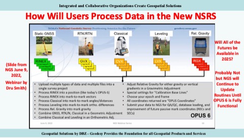
In 2025, NGS will replace all three North American Datum of 1983 (NAD 83) frames and all vertical datums, including the North American Vertical Datum of 1988 (NAVD 88), with four new terrestrial reference frames and a geo-potential datum. As stated in my previous columns – April 2022, April 2021, June 2020 – the new reference frames will rely primarily on Global Navigation Satellite Systems (GNSS) as well as on a gravimetric geoid model. These new reference frames will be easier to access and to maintain than the current NSRS. NGS will provide tools similar to the OPUS suite of routines that will facilitate users’ ability to submit data to NGS to maintain and publish survey marks. See the graphic below.
I would like to highlight that NGS has extended the cut-off date for submitting data for use in the 2022 Transformation Tool. The new cut-off date is Sept. 30 (see below).
This column provided an update on the current set of published orthometric heights in the southeast Texas region based on recent GNSS surveys performed during 2021 and 2022, NGS’s rules for estimating and publishing GNSS-derived orthometric heights using OPUS Projects, and the status of NGS’s GPS on Benchmarks program. Additionally, it highlighted that the NGAC of the FGDC adopted a resolution on the need for the federal government to understand and aggressively address the United States geodesy crisis. This is a good step forward, and I hope that others will follow up with discussions with other organizations such as the OSTP in the White House. Finally, “The Geodesy Crisis” white paper can be downloaded from the American Association for Geodetic Surveying (AAGS) website.
I hope everyone has a happy new year filled with optimism, happiness and a generous amount of enthusiasm and fun.
On Dec. 28, Atwell, a Michigan-based, full-service consulting, engineering, and construction services firm, announced its agreement to acquire Dempsey Surveying Company, expanding business in the Midwest. The deal is expected to close on Dec. 31.
The acquisition of Dempsey Surveying Company, based in Cleveland, Ohio, broadens Atwell’s presence in the Midwest and expands surveying capabilities, as well as other services, to new and existing clients.
Dempsey Surveying Company’s services include topographic surveys, construction staking, boundary services, Federal Emergency Management Agency (FEMA) flood elevation certificates, surface model TINs, GPS services, aerial mapping, and UAV services. The company has a variety of clients across several industries and has maintained more than 50 years of survey records.
This is Atwell’s third acquisition this quarter. In November, Atwell acquired Cross Surveying, a Florida-based land surveying firm, and Ben Dyer Associates, a Maryland-based engineering firm.
CyArk, a California-based nonprofit, used UAVs, lidar and GNSS equipment to scan Big Basin Redwood State Park in Santa Cruz, California and create a model of it. The model shows drastic changes from climate change and the after-effects of the 2020 CZU Lightning Complex Fire.
CyArk was contracted by the California park system and Google Art & Culture to document climate-related changes in the state forest, including the 2020 CZU Lightning Complex Fire, which burned more than 97% of the oldest park in California, destroying historic structures and most of the park. The fire was detrimental to the park’s landscape, which is still plagued by drought.
DJI quad-rotor UAVs, a fixed-wing senseFly UAS, lidar and photogrammetry data brought in by RealityCapture software, and Topcon Positioning Group GNSS receivers among other technologies were used by CyArk to map the large-scale project.
The model created from the flyover of the Big Basin can be seen here.
CyArk digitally documents culturally historical places around the globe in 3D to preserve each site’s story using GNSS and lidar technology. They have worked at more than 200 sites in more than 40 countries.
Geodesy without math equations: Is that possible? The answer is no, but basic geodetic concepts can be described without using complex math equations.
My previous column addressed the geodesy crisis in the United States. (See also this.) The newsletter was highlighted on LinkedIn (thanks, Jay); more than 235 individuals reacted to the post and there were 25 reposts.
I’m pleased so many people are interested in highlighting the discussion of the inverted pyramid. One reader of my column asked for material for non-geodesists to obtain a better understanding of geodetic concepts.
Geodesy does involve advanced mathematics that may not be familiar to some people. That said, there are various online lessons and tutorials that describe the basic concepts without using complex math equations.
As mentioned in my previous column, geodesy is involved with anything related to positioning. For example, have you ever wondered how your phone appears to know where you are on a digital map while you’re walking or driving down the street? Geodesy provides the foundation for all geospatial products and services.
Image: Dave Zilkoski
Location on a Map
A goal of mine has always been to get individuals (young and old) interested in obtaining a better understanding of geodesy. In my opinion, high schools and colleges should include courses that explain to students how their phones know where they are, why the Earth is not a sphere, how the movement of tectonic plates are measured and why, basic concepts of how satellites orbit the earth, and how geographic coordinates are important to making maps and their use in establishing an accurate geographic information system (GIS).
A good first step is to get high school teachers interested in the topic. When I was employed by the National Geodetic Survey (NGS), a group of us worked with local high school students to map their football field using GPS. They acquired observations in the field, and then downloaded the coordinates into their GIS. The teacher was instrumental in integrating the application into the students’ curriculum.
A reader of my last column suggested I provide concrete, meaningful things to lower the barrier of entry. I’m not exactly sure how to lower the barrier of entry — geodesy does require an individual to have a certain level of mathematical knowledge.
Since I retired from NGS, I have helped homeschool my eight grandkids. The one thing that I’ve found is that young students apparently either “like” math or they “hate” math. At least with my grandkids, there doesn’t seem to be an in between.
At this moment, I don’t believe any of my grandkids will become geodesists; well, actually, there’s still a possibility that one may have a “love for mathematics.” It appears that most students don’t really see a reason to learn math. They can use their phones or calculators to do what they need.
The reader suggested that the geodesy community could publish free, high-quality, web-based resources for the public. The reader made the following suggestions:
A set of 3D-printable designs for rudimentary survey tools; alternatively, how to acquire/build the tools in the most economical way possible. Even something that would be considered a “toy” that can be given to a child would be good.
A list of software tools (preferably open source) relevant to the subject and how to use them in this context.
Introductory material intended for young audiences.
This column will provide some free online lessons and tutorials that describe the concepts associated with geodesy and surveying. Some of the online videos are at a level for young audiences, and some are aimed at individuals with more advanced education. Let’s start with the young audience.
Lessons for Kids
The website “Get Kids into Survey” provides materials focused on kids. The website states: “Bringing young people into the exciting world of survey through pioneering content and engaging experiences.” See the boxes titled “Get Kids into Survey Website,” “Get Kids into Survey Website – Poster Page,” and “Get Kids into Survey Website – World Without Surveyors Poster.”
Get Kids into Survey Website
Screenshot: Get Kids lnto Survey
Get Kids into Survey Website – Poster Page
Screenshot: Get Kids into Survey
Get Kids into Survey Website – World Without Surveyors Poster
Screenshot: Get Kids into Survey
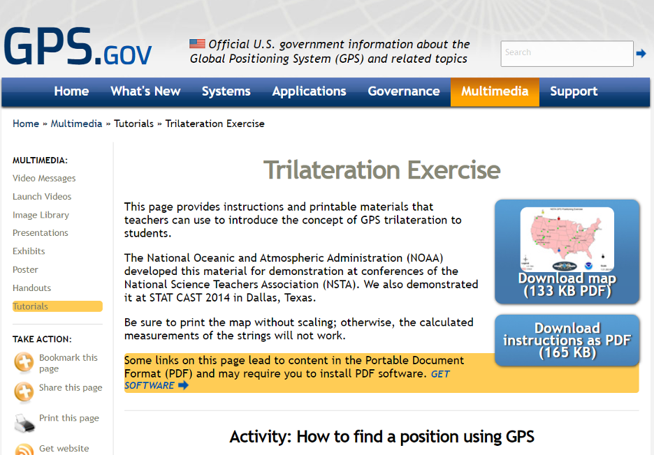
The GPS.gov website has lessons describing GPS that are designed for kids. One lesson introduces the concept of GPS trilateration. The lesson explains how GPS positioning works on two basic mathematical concepts:
trilateration, which literally means positioning from three distances, and
the relationship between distance traveled, rate (speed) of travel, and amount of time spent traveling.
This was developed by NGS for a National Science Teachers Association Conference. You can download both the instructions and map.’
GPS Trilateration Lesson
Screenshot: GPS.gov website
The following are several videos that describe the concept of trilateration.
This video explains trilateration and how the GPS ranges (distances from the satellite to the receiver) are computed.
This video uses distances on a map to describe trilateration.
Here is a detailed description of trilateration and why you need the fourth satellite.
Now, let’s look at some free online lessons and tutorials that describe the concepts associated with geodesy. As previously stated, some of the online videos are at a level for young audiences, and some are aimed at individuals with more advanced education. Most of them describe the concepts using diagrams with narratives, and without complex math equations. NGS provides a number of videos that can be downloaded here.
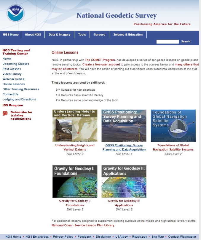
NGS, in partnership with the COMET program, has developed a series of self-paced lessons on geodetic and remote sensing topics. Users have to create a free user account to gain access to the courses. Users will have the option of printing out a certificate upon successful completion of a quiz at the end of each lesson.
The lessons are rated by skill level ranging from “Suitable for Non-Scientists” to “Requires some Prior Knowledge of the Topic.”
The COMET program provides teaching and training resources for the geoscience community. All of the content is completely free, but an account does need to be created. The COMET program is part of the University Corporation for Atmospheric Research (UCAR) Community Programs.
NGS Online Lessons
Screenshot: NGS Website
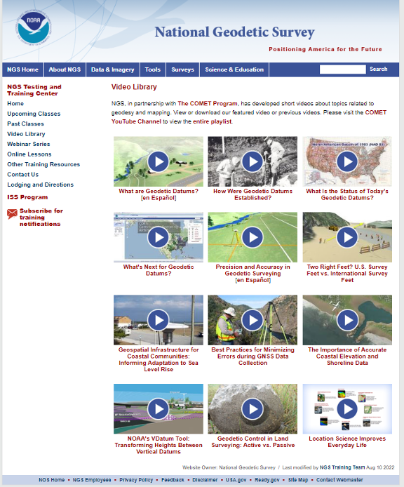
NGS and COMET Educational Videos
NGS also has a website that contains educational videos. Again, NGS, in partnership with the COMET Program, has developed short videos on topics related to geodesy and mapping.
NGS Educational Videos
Screenshot: NGS Website
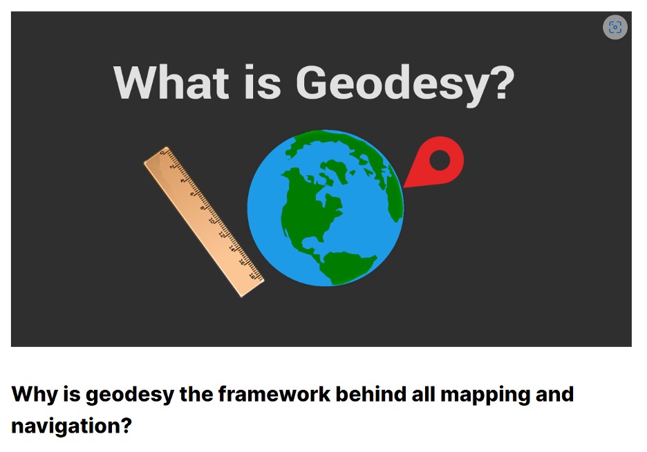
This link provides a tutorial on “Why is geodesy the framework behind all mapping and navigation?” The article states. “If you think about it, the whole field of geomatics lies on the shoulders of geodesists. Because it’s really geodesy that is the framework behind all surveying, mapping and navigation.”
What Is Geodesy?
Screenshot: Gisgeography Website
NASA’s Eratosthenes Estimating the Circumference of the Earth by Looking Down a Well
NASA offers a video titled “Looking Down a Well: A Brief History of Geodesy.” This video explains how it all started when Eratosthenes estimated the circumference of the Earth by looking down a well. It highlights how, over time, the field of geodesy has expanded and evolved dramatically, and how NASA uses technology such as radio telescopes, ground surveys, and satellites to contribute.
NASA’s Video on Looking Down a Well
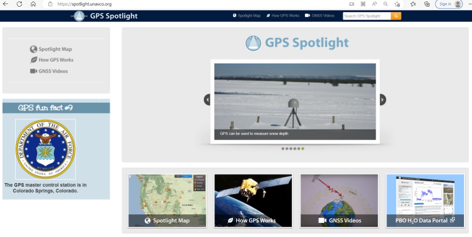
UNAVCO Measures Plate Tectonics with Geodesy
UNAVCO, a non-profit university-governed consortium, facilitates geoscience research and education using geodesy. UNAVCO has a video that describes the tectonic plates and how geodesists measure their movements. Another UNAVCO video describes what geodesy actually is, as well as geodesy’s application in our everyday lives (UNAVCO’s 2017 USIP geoscience video production). Visit UNAVCO’s website to learn more about its mission.
Geodetic Software Tools
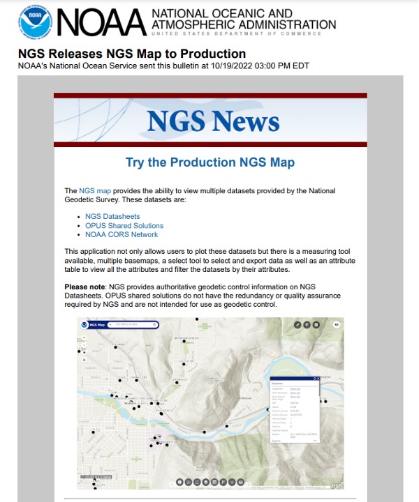
NGS provides tools that focused on meeting the needs of the surveying and mapping community. A few may be of interest to non-geodetic individuals. A map tool can be used to locate marks near someone’s location.
Production NGS Map
Screenshot: NGS Website
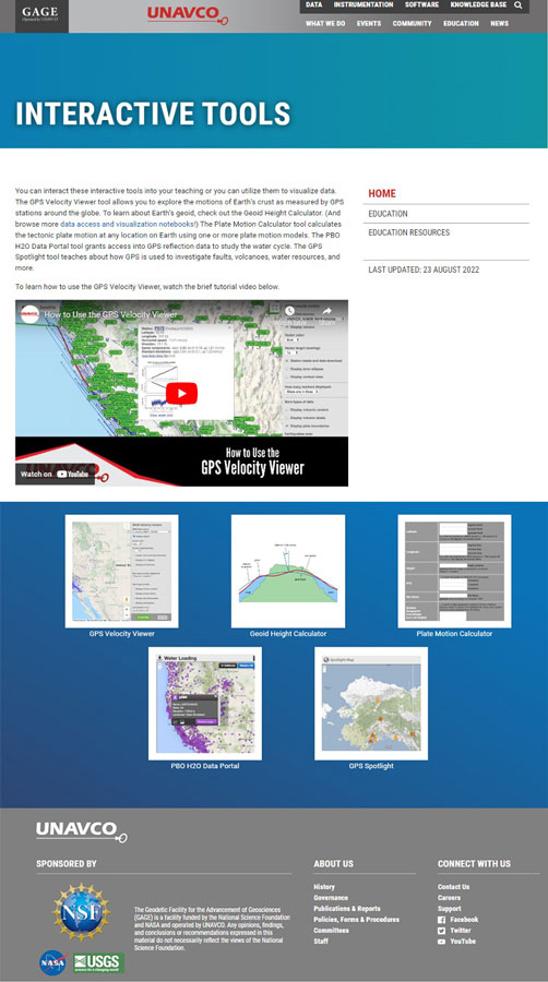
UNAVCO also has interactive tools that may be of interest to geospatial users. See the boxes below titled “UNAVCO Interactive Tools” and “UNAVCO Spotlight.”
Now, let’s address the 3D printing of surveying equipment and tools. I’m not familiar with using a 3D printer, but I found several websites that provide information on surveying equipment. Some of the sites provide free information and others charge for their services. See the websites 3D Printer of Total Station and 3D Printer of GNSS Equipment.
3D Printer of Total Station
Screenshot: CULTS Website
3D Printer of GNSS Equipment
Screenshot: 3dmdb Website
I’m pleased a lot of people are interested in highlighting the discussion of the inverted pyramid. As commented by several individuals in the LinkedIn responses, the surveying and remote sensing (which includes photogrammetry) communities are experiencing the same crisis as geodesy. In my opinion, they are all related, because the surveying and mapping community provides tools other disciplines use.
As stated in my last column, the surveying and mapping community can do the following to help:
actively market geodesy in high schools as a rewarding career for the math stars before college entry
build back, support and sponsor geodesy programs at select universities; this support needs to be strategic with backing from the highest levels of the U.S. government
encourage U.S. government support in the form of grants, professional development of staff, and research collaborations/affiliations.
As previously mentioned, one of my goals has always been to get individuals (young and old) interested in obtaining a better understanding of geodesy. I hope this column helps to whet the appetite of some individuals to obtain a better knowledge of geodesy. Maybe even some high school and college teachers will introduce geodetic concepts in their lectures.
Writing about the geodesy crisis is a good first step, but we need to find champions that can influence high school and university teachers and administrators, federal and state government program managers, and congressional representatives.
Please feel free to email me at [email protected] if you have suggestions on how to lower the barrier of entry into the world of geodesy.
CHC Navigation has released LandStar8, a field surveying and mapping application for Android devices. LandStar8 is designed to be flexible and user-friendly for surveying and mapping tasks.
LandStar8 is versatile, modular and customizable for topographic tasks such as surveying, stake out, cadastral, mapping and geographic information systems (GIS). Building on the legacy of LandStar7, the new LandStar8 provides features such as a refined user interface, streamlined workflows, faster operation, and integrated cloud services.
“With LandStar8, we want to provide our users with unprecedented field experience,” said Rachel Wang, product manager of CHC Navigation’s Surveying and Engineering Division. “LandStar8’s modular design allows users to customize the interface according to their usage habits, making it easier and more efficient for field crews to work.”
Cloud connectivity is built in, for backup, data storage or remote technical support.
LandStar 8 has a simple and intuitive layout with large map windows and sharp graphics. Users can hide features they rarely use and display only those they need.
On LandStar8, users can copy coordinate settings, control and staking points from another handheld controller by scanning a QR code. Projects can be edited and sorted by history and attributes. Custom coordinate systems, geoid models and coding libraries can be updated at any time by using resource packages. LandStar8 also features a terrain calibration wizard designed specifically for non-expert users.
A proprietary MetaCAD graphics engine opens DWG and DXF base maps faster and with smoother rendering. DXF files up to 200 MB can be opened in less than 10 seconds. LandStar8 also supports opening external reference files, automatically recognizes CAD length units, and allows editing of CAD base maps directly in the field.
LandStar8 is designed around a comprehensive cloud-based architecture that supports project backup, collaborative work and data storage. Its remote support capabilities help the office helpdesk resolve user problems and provide personalized technical assistance. A “share code” feature allows users to transfer project data between desktop computers and field controllers or among field controllers quickly to further boost work efficiency.
A roundup of recent products in the GNSS and inertial positioning industry from the November 2022 issue of GPS World magazine.
OEM
GNSS Module
For UAV, precision agriculture and autonomous machines
Photo: Unicore Communications
The UM982 GNSS module is a high-precision, dual-antenna real-time kinematic (RTK) positioning and heading module. It supports BeiDou B1I/B2I/B3I; GPS L1/L2/L5; GLONASS L1/L2; Galileo E1/E5a/E5b, QZSS L1/L2/L5; and SBAS in dual-antenna mode. The highly integrated, compact (16 mm × 21 mm × 2.6 mm) module can reduce the design area of an OEM board by 72% compared to previous modules. Power consumption is less than 0.6 W. The NebulasIV GNSS system-on-chip is a key part of the UM982’s navigation system. The NevulasIV integrates RF, baseband and high-precision algorithms on a single chip, with supporting functions built in. High-level performance indicators include raw observation accuracy, RTK positioning accuracy, precise point positioning accuracy, and time to first fix. The two antennas can independently participate in deriving an RTK solution and outputting the positioning results.
Alternative to ceramic patch provides omni-directional performance
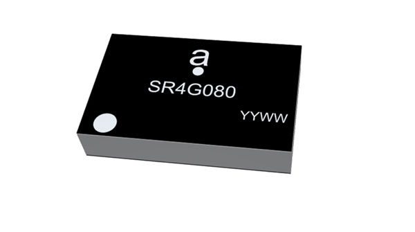
Photo: Antenova
The Agosti (part number SR4G080) is a new miniature surface-mount-designed (SMD) antenna for GNSS applications. It measures 9.0 mm x 5.8 mm x 1.7 mm and operates with exceptional efficiency in a reduced space on a corner of a printed circuit board. It has a small ground-plane requirement of 40 mm x 20 mm, 70 mm x 25 mm and 80 mm x 30 mm, making it suitable for small form-factor designs such as wearable devices, trackers and onboard diagnostics.
Housed Dual-Band antenna with Accutenna technology
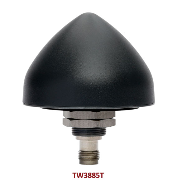
Photo: Tallysman
The dual-band TW3885T antenna supports GPS/QZSS L1/L5; Galileo E1/ E5a/b; BeiDou B1/B2/B2a; GLONASS G1/G3; and satellite-based augmentation systems in the region of operation: WAAS (North America), EGNOS (Europe), MSAS (Japan) or GAGAN (India). It is housed in a through-hole mount, weatherproof (IP69K) enclosure. It mitigates the effects on GNSS receivers of new signals or harmonic frequencies from adjacent LTE bands on the radio-frequency spectrum. For permanent installations, L-bracket (PN 23-0040-0) or pipe (23-0065-0) mounts are available. Tallysman provides an antenna installation guide that recommends a 100 mm –125 mm ground plane and provides antenna installation and cable connector waterproofing best practices.
Simplifies product development for high-precision applications
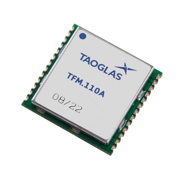
Photo: Taoglas
The TFM.110A is the first in a new series of high-precision, multi-band GNSS front ends for autonomous vehicles, precision agriculture, automotive applications and robotics. It comes fully integrated with two cascaded low noise amplifiers (LNA) and pre-filters in a small, low-profile, shielded surface-mount package. When used between the device’s GNSS receiver and antenna, the two-stage amplifier solution eliminates the need for complex and challenging onboard filter and amplifier circuits. It supports L1, L2 and L5 bands and enables seamless signal transmission, signal purity and position accuracy in high-precision applications.
Provides interference, spoofing, encryption and authentication capability
Photo: IFEN GmbH
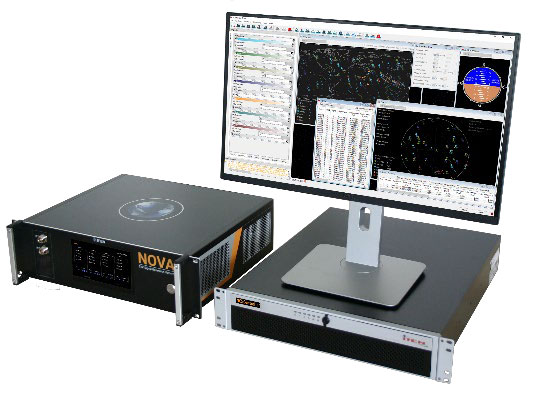
Version 2.8 of the NCS Nova RF signal simulator offers advanced capabilities. With integrated interference generation capability, the Nova can generate coherent interference signals with a signal power of up to –30 dBm. The ability to assign two users to one RF output enables integrated spoofing scenarios with a single RF output, meaning spoofing is available even with an entry-level single RF Nova. The new release has advanced navigation message authentication simulation capability compliant to User ICD 1.0 for the Galileo E1-B OSNMA, meaning specific OSNMA events can be simulated — key to ensuring compliant receiver behavior. Supported events include renewal and revocation of both a public key and a TESLA keychain. GPS cross-authentication and generation of Galileo E6-C encrypted codes are also supported.
Enables first responders to locate callers on floor levels
Photo: Polaris Wireless
Z-axis location service enables the pinpointing of a smartphone user within one floor level inside a multi-story building. The technology — demonstrated to meet the 3-meter vertical location accuracy requirement of the Federal Communications Commission (FCC) — is integrated into Schok Gear’s newly released flip phones. The Schok phones provide consumers with a simple, powerful device. Adding indoor and vertical location to these phones enables first responders to locate all wireless 911 callers with floor-level accuracy in multi-story buildings.
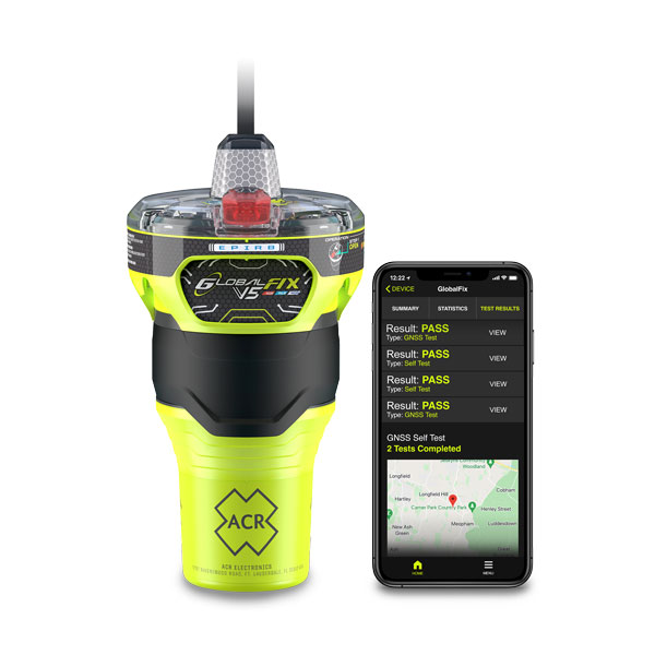
The new ACR Electronics GlobalFix V5 Emergency Position-Indicating Radio Beacon (EPIRB) and ResQLink AIS Personal Locator Beacon (PLB) have integrated the automatic identification system (AIS) to increase the speed of location and aid. They also are compatible with Return Link Service (RLS) alerting. The combination of services ensures faster rescue and increases chance of survival of both boat (EPIRB) and crew (PLB). The safety beacons deliver mobile connectivity to a cell phone with a free mobile app, made possible with the addition of near-field communication technology in the beacons. With the app, users can monitor their beacons, review self-test results, view GNSS test locations, and monitor beacon performance and maintenance by scanning the beacons with their mobile phones. Besides GNSS positioning, the lightweight beacons have 406-MHz Cospas-Sarsat distress signal with MEOSAR compatibility and 121.5-MHz local homing signal.
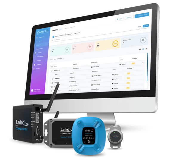
The Canvas Device Manager simplifies workflows for configuration and maintenance of internet of things (IoT) device deployments. It enables users to easily set up devices, monitor performance, and keep software up-to-date across the entire IoT device fleet. Device parameters can be remotely managed, and performance monitored. Canvas enables users to organize large numbers of devices to quickly build and maintain IoT solutions, and software updates can be remotely and rapidly deployed, thwarting security attacks.
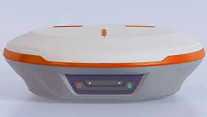
The N2 Palm RTK GNSS receiver is suitable for surveying, mapping and construction. It has a highly integrated main board and a three-in-one antenna, yet weighs 0.72 kg with battery and measures 48 mm. Powered by ComNav’s SinoGNSS K8 high-precision module, the N2 can track 1,590 channels, including all existing and planned signals of GPS, BDS-2, BDS-3, GLONASS, Galileo, QZSS and SBAS. Its advanced satellite-tracking technology ensures it works well even in harsh environments, such as under heavy foliage or close to buildings. A third-generation inertial measurement unit (IMU) makes the N2 immune to magnetic disturbance, which greatly improves its reliability. Pole-tilt compensation of up to 60° allows surveyors to locate points within 2.5 cm. By using the company’s Quantum algorithm, the N2 achieves calibration-free operation — after 10 seconds of initialization, users can make tilt measurements with centimeter-level accuracy for an extended period, greatly improving efficiency.
Airbus has added 30-cm Pléiades Neo imagery to its OneAtlas Living Library service. The new data source will complement the service which already allows users to instantly access a premium catalogue of Pléiades 50 cm and SPOT 1.5 m data via streaming, download and API. The Living Library provides frequent updates over urban areas, airports, harbors and military sites to name a few. Imagery is updated every day and processed in the cloud, with flexible options for integration into GIS workflows. With the OneAtlas Living Library, Airbus offers a pay-per-order option but also a subscription-based service that allows users to access premium content quickly available into their account, as well as a deeper archive of more than 10 years of imagery by Pléiades and SPOT satellites at a higher incidence angle and cloud coverage threshold, which will be available in just a few hours. OneAtlas also provides access to several other data services, such as reactive tasking, that allows users to task a full suite of optical and radar satellites, including Pléiades Neo, or access more than 15 years of global radar data, as well as the ability to download the WorldDEM product suite among others.
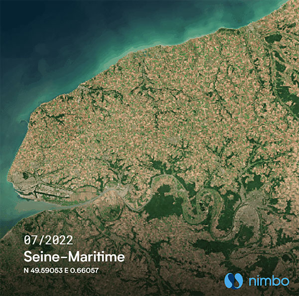
Free, user-friendly tool shows the Earth’s changes
Photo: Kermap
The Nimbo Maps platform provides monthly 10 m-resolution images of changes on Earth in a user-friendly format. The images are chronological, seamless and free of clouds, and include intuitive comparison timelapse features. The platform, developed by French startup Kermap, relies on innovative artificial intelligence methods to process satellite images supplied by the European Union’s Copernicus program through its Sentinel missions. APIs automatically retrieve data extracted from satellite imagery, providing Kermap customers with real-time, strategic, value-added information in the fields of agriculture, land planning and environmental transitions. Current coverage includes Europe, the Middle East and the United States, with plans to provide global coverage by early 2023.
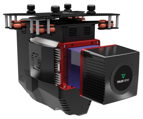
The TrueView 655/660 3D imaging system uses the Riegl miniVUX-3UAV laser scanner and three fully integrated mapping cameras (right, left and nadir) for high-accuracy mapping with excellent vegetation penetration and wire detection. Previous TrueView 3D systems carried dual oblique cameras to maximize mapping coverage. The TrueView 655/660 adds a third RGB camera, allowing for imagery directly below the sensor to be captured. The third camera provides a direct view of the ground below to maximize data collection for time flown, while improving the quality of photogrammetry and colorized point clouds.