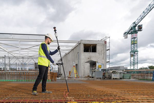
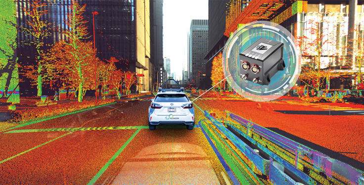
Hexagon | NovAtel’s CPT7 integrates a GNSS receiver and an INS to deliver up to centimeter-level accuracy. (Photo: Hexagon | NovAtel)
We discussed mobile mapping with Bryan Leedham, product manager of enclosures and post-processing software, NovAtel, Autonomy & Positioning division, Hexagon.
How do you define mobile mapping?
It is getting broader in scope, as more folks find reasons to map the world. The key goal is to capture reality from mobile platforms to build a digital representation of reality for some large area, such as a city, a road or a factory. Most of the time, that means from a ground vehicle on public roads.
It’s also safer and faster than traditional surveying because you don’t have to stop traffic or dodge it.
Right! In an ideal world, rather than spending days setting up traditional survey equipment, you could strap some sensors on a mobile platform and gather accurate map data in minutes.
What are the key remaining technical challenges?
Picture one of Google’s or Waymo’s mapping vehicles. The first sensors that come to mind are GNSS, inertial, lidar and radar. Each of those has its own unique strengths and weaknesses. The first technical challenge that remains is to mature each of those technologies for a lower enough cost that it’s affordable.
Right now, mobile-mapping vehicles are quite expensive, especially in areas where some of these sensors will struggle more than others. To map very dense urban spaces — with underground areas, overpasses and tall buildings where GPS is challenged — you need a very strong localization system that can survive those conditions for however long it takes to drive through them. If I’m building a car to map rural Alberta, I could choose much cheaper sensors than if I were trying to map downtown Chicago every week.
On the flip side, you must deal with the massive amounts of data collected.
Yes, that is a very large challenge. Lidar data, in particular, is guilty of generating very large point clouds. It’s a balancing act. More accurate and higher resolution maps require lidar sensors with even denser point clouds. So, you need data management and sufficient processing power to get accurate results quickly.
What are the key technical challenges in sensor fusion?
Sensor fusion is how we approach the goal of mapping as accurately as possible in increasingly difficult environments. On their own, GNSS receivers struggle in obstructed areas but, when you pair them with other sensors, they become very complementary.
Lidar and cameras, for example, are quite good at measuring the distance to nearby objects and at classifying them, but they have no idea where they are relative to one another. Likewise, if you let an IMU [inertial measurement unit] sit in your car, it will no longer know its location. However, once you give it a position update, it is very good at maintaining a trajectory over a short period of time. When you combine absolute and relative localization, all the sensors play to their own strengths.
What is NovAtel’s SPAN software?
It stands for synchronous position, attitude and navigation. It is the sensor-fusion software that combines the GNSS, inertial and whatever other sensors. It is based on core NovAtel GNSS receiver software. We can use NovAtel receivers in combination with IMUs from a wide range of manufacturers and, in the future, hopefully, other sensors from a variety of manufacturers as well.
SPAN started with blending just GNSS and inertial but we’re now researching how to bring in such things as lidar and cameras. Autonomous Stuff, another Hexagon company, works on the greater sensor fusion using SPAN as well.
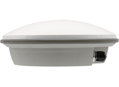
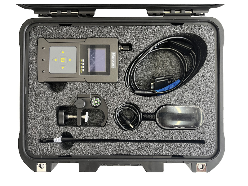
Harxon has launched a high-precision GNSS antenna, the HX-CSX633A. The HX-CSX633A has an upgraded architecture for more durable use and more flexible installations, making it suitable for agricultural vehicles, small robots and surveying applications.
Photo: Harxon
The HX-CSX633A features a durable, future-proof design with an IP67 waterproof housing. It meets MIL-STD-810-H for vibration and shock, increasing robustness for use under high-vibration conditions. The HX-CSX633A supports flexible installations including magnetic mount, screw mount and pole mount. Consequently, integrators can be confident this powerful antenna can be used in system designs for years to come, the company said.
The HX-CSX633A is fully functional, powerful and stable. The phase center remains constant with a multi-point feeding design. The ability to receive low-elevation signals with high gain and wide beamwidth makes it suitable for tracking visible satellites in tough environments, Harxon said.
The antenna’s low-noise amplification (LNA) features excellent out-of-band rejection, which can suppress electromagnetic interference and prevent disconnection when receivers are operated in complex electromagnetic environments.
Key Features of the HX-CSX633A:
supports GPS, GLONASS, Galileo, BDS, QZSS, IRNSS and SBAS signal reception
stable phase center guarantees positioning accuracy within the millimeter-level
strong anti-interference ability to endure challenging operating environments
Burkhard Boeckem and a Boston Dynamics robot dog share insights into smart digital realities. (Photo: Hexagon)
At HxGN LIVE Global 2022, in-person attendees experienced the full breadth of what the flagship conference has to offer for the first time since 2019. The conference is taking place this week at the Venetian hotel in Las Vegas.
Tuesday began with a keynote address by Burkhard Boeckem, chief technology officer, who discussed the importance of smart digital realities and their role in the potential of the metaverse to impact and enhance the physical world. Hexagon’s technology platform Xalt enables intelligence at scale. By integrating sensors and data integration across systems and solutions, like the BLK series and HxDR, Xalt provides the next level of connectivity to harness and utilize data for autonomous systems.
Summit-specific keynotes by speakers from Hexagon, its partners and sponsors provided expertise on issues, solutions and innovations shaping and reimagining various industries.
The Digital Innovation in Construction summit begins. (Photo: Hexagon)
Tuesday was also the first day of breakouts for all summits, with more than 100 sessions throughout the day covering everything from training and tips for Hexagon products to project success stories, panel discussions of industry trends, and a look at the precision engineering of Formula 1 cars with Hexagon partner Oracle Red Bull Racing. Sessions continue through the close of the conference on Thursday.
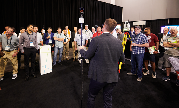
The Zone, the massive technology expo floor, officially opened for the first time this morning, where attendees explored some of the latest advancements, products and solutions available across seven summit-specific “islands” offering hands-on demonstrations and an opportunity to ask the questions that will help them make the best use of autonomous technology in their field.
Surveyors get the lay of the land at the Pure Surveying Island. (Photo: Hexagon)Advances in digital construction were provided by Leica Geosystems. (Photo: Hexagon)
In the evening, summit events took attendees around the grounds of the Venetian resort for various experiences.
A roundup of recent products in the GNSS and inertial positioning industry from the June 2022 issue of GPS World magazine.
SURVEYING & MAPPING
Base/Rover
For survey-grade GNSS accuracy anywhere
Photo: Bad Elf
A base/rover feature built upon the Flex GNSS receiver brings affordable centimeter-level accuracy to surveyors and geospatial professionals working anywhere in the world. The solution consists of two Flex GNSS receivers and two UHF radios, allowing customers to perform high-accuracy field data collection in areas where traditional real-time kinematic (RTK) corrections or cellular coverage is not available. Existing Flex customers can upgrade by adding Flex radio kits (pictured). The Bad Elf Flex enables data collection either as a standalone receiver or paired with apps on iOS or Android phones and tablets.
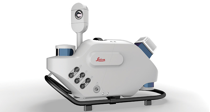
The Leica Pegasus TRK reality-capture mobile-mapping system features artificial intelligence (AI), autonomous workflows and intuitive interfaces. To comply with privacy regulations, its AI can identify and blur identifiers, such as people and vehicles, in real time. Features include advanced dynamic laser scanning and an expandable imagery system for recording, measuring and visualizing. It enables long-range mobile mapping for asset management, road construction, rail, critical infrastructure, utilities and more. The system also can create high-definition basemaps for autonomous vehicles.
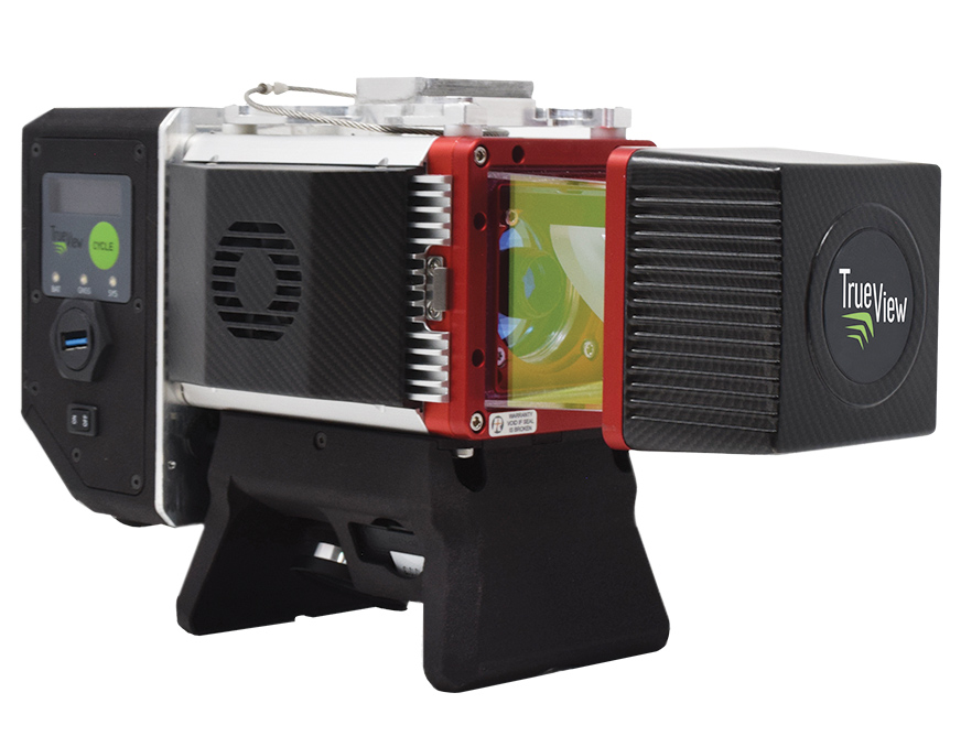
The True View 645/650 is the latest 3D Imaging System (3DIS) from GeoCue. Combined with the True View EVO data-processing software suite, it includes the full post-processing software workflow and directly integrates with Applanix POSPac. EVO supports the creation of project deliverables including ground classified point clouds, surface models, contours, digital elevation models (DEMs), volumetric analysis and wire extraction. The system delivers colorized lidar deliverables with accuracy better than 3 cm root-mean-square-error (RMSE) for the True View 645, and better than 2 cm for the True View 650.
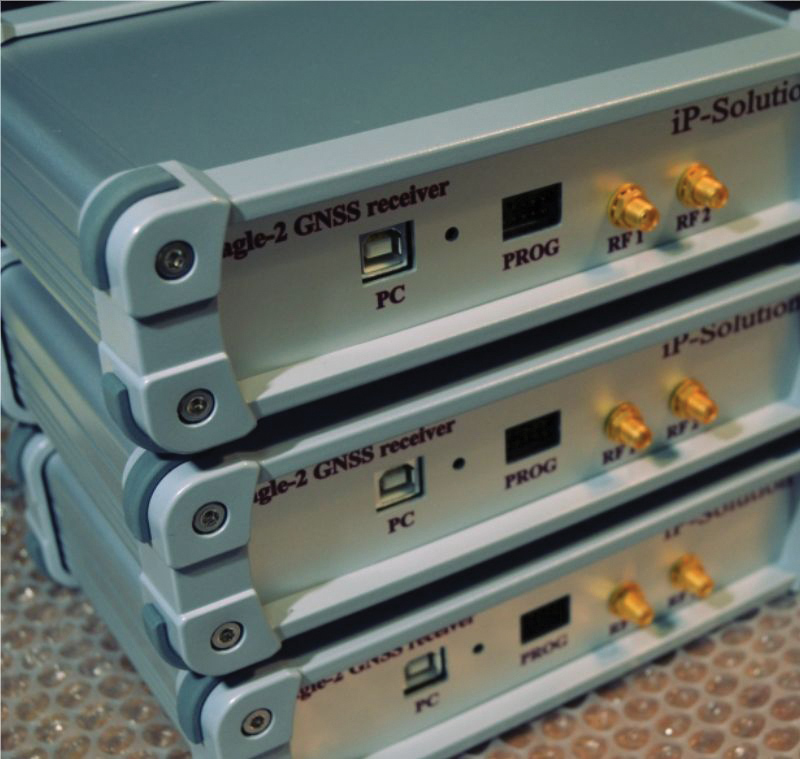
The Eagle-2 works with software-defined receivers in real time or records GNSS signals for post-processing. For post-processing, Eagle-2 supports most third-party receivers, such as MATLAB and C/C++ receivers. The front end allows a user to work with two perfectly synchronized channels connected to two antennas. The Eagle-2 supports GPS, Galileo, GLONASS , BeiDou, QZSS and SBAS.
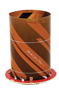
The housed HC885XF and embedded HC885EXF dual-band eXtended Filtering (XF) antennas receive GPS/QZSS L1/L5, GLONASS G1/G3, Galileo E1/ E5a/b, BeiDou B1/B2/B2a and L-band corrections services. They have been tuned to provide optimal support for the entire L1/G1/E1/B1/L-band correction and L5/G3/E5/B2 bands. The housed version, HC885XF, weighs ~42 g and is enclosed in a robust, military-grade IP67 plastic enclosure. The embedded version, HC885EXF, weighs ~8 g and is easily mounted with an embedded helical mounting ring.
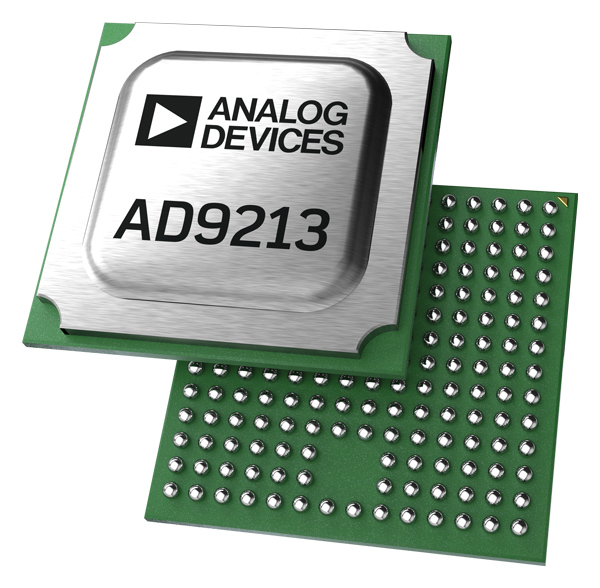
Sets performance benchmarks for harsh environments
Photo: Analog Devices
The AD9213S-CSH is a highly integrated RF analog-to-digital converter that handles 12-bit, 10.25-giga-samples per second. It is the company’s fastest ADC available for the space environment. The AD9213-CSH enables the next generation of software-defined systems for satellite communications, radar and remote sensing. The high sample rate and integrated post-processing enable further performance gains for narrow-band applications.
Skyward has published a free ebook, Adding Drones to the Enterprise, to provide guidance on establishing a corporate drone program. According to Skyward, the most efficient and effective drone programs are the lowest risk and most compliant. Topics covered include how to present the business value of a drone operation to corporate executives; how risk managers can optimize the workflow to ensure maximum safety; best practices for risk mitigation and regulatory compliance; tips for collaborating with legal and compliance teams on a general operating manual; and how to provide full transparency to corporate stakeholders.
DJI’s all-in-one solution for professional drone operators includes the DJI Matrice 30 (M30) drone integrated with DJI FlightHub 2 fleet-management cloud software and DJI Dock for autonomous docking and recharging. The integrated solution is suitable for Enterprise drone users such as public safety agencies, infrastructure inspectors and energy operators. The M30 model is designed for rugged professional uses, while the fact that it fits in a backpack makes transportation and setup fast. The DJI Dock is an autonomous takeoff, landing and charging station allowing fully automatic, programmed flights with the DJI M30 Series (Dock Version). After setup, the fully charged M30 drone can take off from the dock through FlightHub 2 programmed automatic missions anywhere within a seven-kilometer radius.
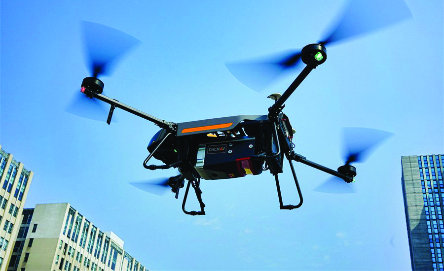
The AlphaAir 1400 (AA1400) and AlphaAir 2400 (AA2400) lidar systems are lightweight, compact airborne scanners easily installed on various UAV platforms or small survey aircraft and helicopters. They are adapted to high-density point-corridor mapping applications, day or night, under leaf-on and leaf-off conditions or with dense vegetation to provide reliable results. Combined with industrial-grade GNSS receivers and high-precision inertial measurement units (IMUs), the AA1400 and AA2400 provide 2 cm to 5 cm survey-grade accuracy. They also integrate Riegl VUX lidars with waveform-lidar technology, allowing echo digitization and online waveform processing.
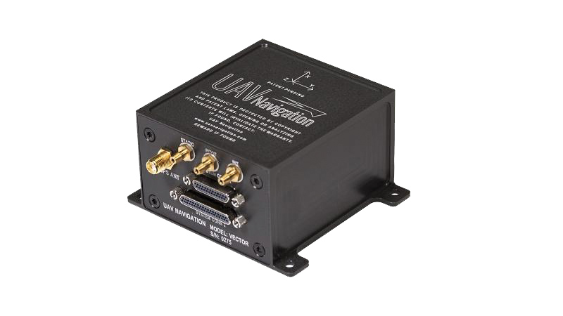
The VECTOR-600 is a robust, dependable autopilot with built-in physical and logical redundancy, allowing it to survive all individual sensor failures while maintaining accurate estimates of attitude and position. It works for fixed-wing, rotary-wing and vertical-take-off-and-landing UAVs. It provides exceptional performance in GNSS-denied environments and when there is a jamming threat. The VECTOR-600 features high quality components and an electromagnetic-resistant design tested to MIL-STD 461.
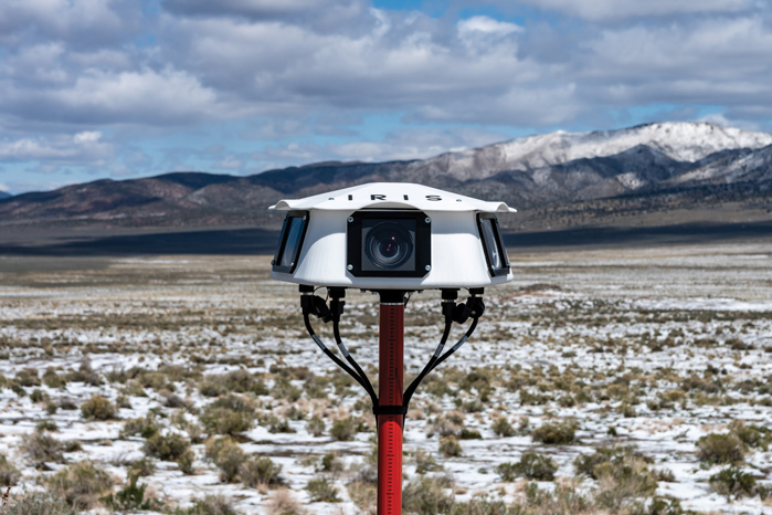
Casia G is a ground-based detect-and-avoid surveillance solution that provides 360° optical detection with alerts. It enables operators to avoid both cooperative and non-cooperative aircraft for safe beyond-visual-line-of-sight (BVLOS) flight. Casia G creates a perimeter of monitored airspace for UAVs to perform work safely, without additional payload. It is suitable for operations in fixed or temporary locations, supporting drone-in-the-box operations and augmenting or replacing human visual observers. Casia G sees the entire sky, with uniform probability and resolution, 10 times per second, covering a majority of small UAS use cases.
Will GPS modernization and improvements in GPS receivers and antennas reduce or even eliminate the need for correction services for most applications?
Julian Thomas, managing director, Racelogic
“For most applications, I think the answer is yes, the need for correction services will be reduced. When you can get <1m without external corrections, the majority of conventional accuracy requirements are fulfilled. However, increases in accuracy always open up new applications for GPS, so correction services will still be required.” — Julian Thomas
Racelogic
Miguel Amor, chief marketing officer, Hexagon’s Autonomy & Positioning Division
“Correction services will continue to be in demand for those markets and applications requiring precision and accuracy below a few inches, 2-3 sigma confidence levels and high reliability, availability and integrity. While ionospheric errors have been low in the past 15+ years, correction services will also provide ionospheric models beneficial in periods of higher activity. Even as there are improvements in user equipment and signal modernization, the demand for correction services will increase in line with these improvements and new functionalities to enable more markets and applications worldwide.” — Miguel Amor
Hexagon’s Autonomy & Positioning Division
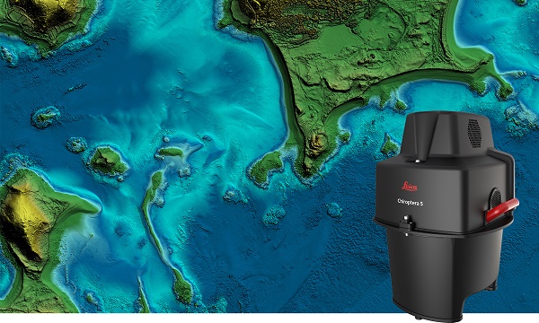
The new Leica Chiroptera-5 is a high-performance airborne bathymetric lidar sensor for coastal and inland water surveys.
Offered by Leica Geosystems, Chiroptera-5 provides 40% higher point density, a 20% increase in water-depth penetration, and improved topographic sensitivity for generating more detailed hydrographic maps.
The technology increases the depth penetration, point density and topographic sensitivity of the sensor compared to previous generations. It delivers high-resolution lidar data supporting applications such as nautical charting, coastal infrastructure planning, environmental monitoring and landslide and erosion risk assessments.
Chiroptera-5 combines airborne bathymetric and topographic lidar sensors with a four-band camera to collect seamless data from the seabed to land. With a higher pulse repetition frequency (PRF), the new technology increases point density by 40% compared to the previous generation system, collecting more data during every survey flight.
Improved electronics and optics increase water-depth penetration by 20% and double the hydrographic sensitivity to capture larger areas of submerged terrain and objects with greater detail. The high-performance sensor is designed to fit a stabilizing mount, enabling more efficient area coverage, which decreases operational costs and carbon footprint of mapping projects.
Leica Geosystems’ signature bathymetric workflow supports the sensor’s performance. Introducing near real-time data processing enables coverage analysis immediately after landing, allowing operators to quality control the data quickly before demobilizing the system.
The Leica Lidar Survey Studio (LSS) processing suite provides full waveform analysis and offers automatic calibration, refraction correction and data classification, as well as advanced turbid water enhancement.
Supporting environmental research
Combining superior resolution, depth penetration and topographic sensitivity, Chiroptera-5 provides substantial benefits for various environmental applications such as shoreline erosion monitoring, flood simulation and prevention, and benthic habitat classification.
Bundled with the FAAS/EASA-certified helicopter pod, the system enables advanced terrain-following flying paths for efficient river mapping and complex coastlines surveys. Owners of previous-generation systems are offered an easy upgrade path to Chiroptera-5 to add capabilities to their existing sensor and leverage their initial investment.
“The first-generation Chiroptera airborne sensor was flown in 2012. During its 10 years of operation, the system has seen constant evolution that continuously improved the productivity and efficiency of the entire bathymetric surveying industry,” said Anders Ekelund, vice president of airborne bathymetry at Hexagon. “By collecting detailed data of coastal areas and inland waters, Chiroptera-5 provides an invaluable source of information that supports better decision making, especially for environmental monitoring and management, in line with Hexagon’s commitment to a more sustainable future.”
My April column addressed the vertical movement at the NOAA CORS Network (NCN). The values at the sites indicate the potential movement of marks in the area of the CORS. The rates are based on GNSS data and have an estimate of error associated with them.
As I mentioned in my previous column, I’m not sure how the National Geodetic Survey (NGS) will address the vertical movement effects in the new, modernized National Spatial Reference System (NSRS). That said, NGS will be monitoring the CORS and looking for trends to help describe the vertical movement at the CORS. These trends are an indication of what may be happening in that area.
As stated in previous columns, orthometric heights in NAPGD2022 will be defined through ellipsoid heights and a geoid model, for example GEOID2022. In addition to the movement of individual marks due to crustal movement, there are geophysical reasons for changes in the geoid that affect the orthometric height of a mark. Therefore, changes in the geoid model will be very important to users estimating orthometric heights using GNSS.
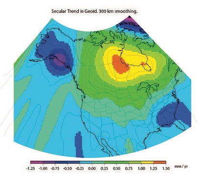
As stated in the NOS NGS 64 report, NGS has set a goal of maintaining geoid accuracy at 1 centimeter (1 standard deviation) in both absolute and differential geoid undulations. The box titled “Figure 13 from NOS NGS 64 Report” depicts an estimate of the secular change in the geoid. As indicated in the plot, the changes are very small, ranging from -1.25 mm/year to 1.5 mm/year.
What I find interesting is the small negative change in the southeastern United States. There are other drivers for geoid changes. This column will address some of these changes and what they mean to users.
Secular geoid change
Figure 13 from NOS NGS 64 Report (Image: NGS)
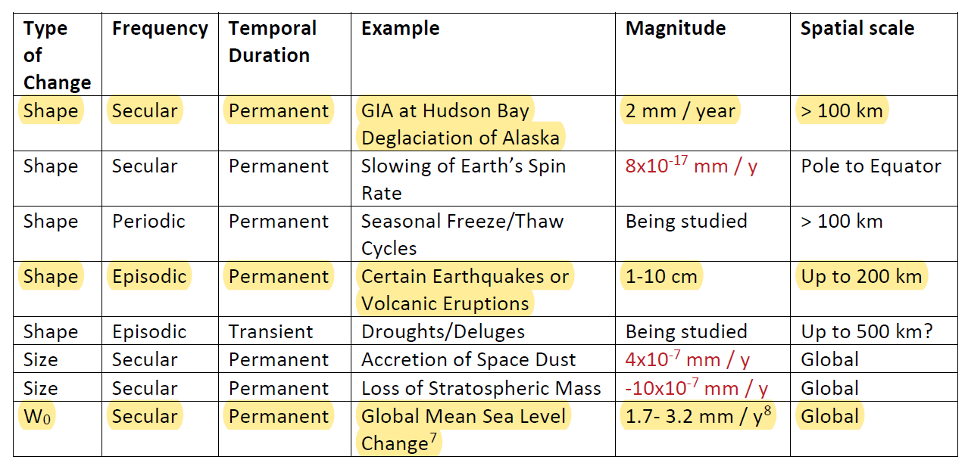
As mentioned in many of my articles, the new, modernized NSRS has a time-dependent component. This includes the geoid model. Table 5-1 from NOS NGS 64 report are examples of some of the physical processes being investigated by NGS to account for changes in the geoid. (See the box titled “Some of the geophysical drivers of geoid change.”)As mentioned in the NOS NGS 64 report, the magnitudes in red have already been determined to be too small for NGS to model. The examples highlighted in yellow have magnitudes that are significant and NGS will attempt to account for these changes to the geoid.
Table 5-1: Some of the geophysical drivers of geoid change
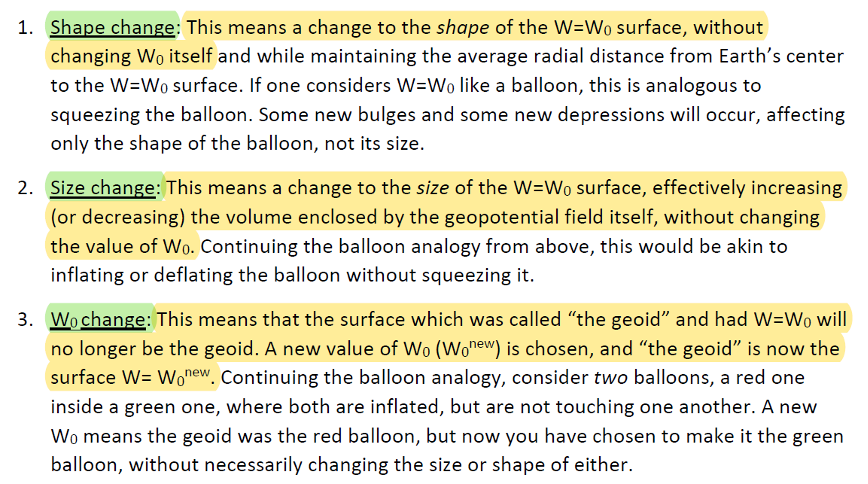
NGS classifies the changes in the geoid in three different groups: Shape Change, Size Change, and W0 Change. The box titled “The Groups of Geoid Change” provides NGS’s definition and explanation of the terms.
The groups of geoid change
NGS’s report on their Geoid Monitoring Service (GeMS) program provides figures that depict an estimate of the secular geoid rate trend based on the NASA GSFC mascon model. See the boxes titled “Estimate of Geoid Rate Over CONUS” and “Estimate of Geoid Rate Over Alaska.” For more details on GeMS, download the report NOAA Technical Report NOS NGS 69: A Preliminary Investigation of the NGS’s Geoid Monitoring Service (GeMS), and read my December 2019 Survey Scene column. The secular geoid rate trend is an example of the geoid changing its shape, but not the W0 value. What this means is that the local geoid undulations will change, but the overall size of the geoid will not.
Estimate of geoid rate over CONUS
Figure 32: Geoid rate over CONUS based on the GSFC mascon model [mm/yr] (Image: NOAA)Estimate of geoid rate over Alaska
Figure 33: Geoid rate over Alaska from GSFC mascon model [mm/yr] (Image: NOAA)These changes in the geoid are fairly small values (+/- 1.3 mm/year), but they will accumulate over a decade. As previously stated, NGS’s goal is to maintain geoid accuracy at the centimeter level (1 standard deviation) in both absolute and differential geoid undulations. In my February 2022 column, I discussed how coordinates change because Earth’s surface is moving due to the movement of major tectonic plates. It’s fairly obvious how the tectonic shift affects horizontal coordinates, but earthquakes and volcanic eruptions can also cause large shifts in vertical coordinates.
In recent history, on May 18, 1980, geologists watched in awe as Mount St. Helens erupted in a gigantic explosion. After the eruption, the volcanic cone of Mount St. Helens had been completely blasted away; the peak, which was at an elevation of 9,677 feet (2,950meters) was changed to a horseshoe-shaped crater with an elevation of 8,363 feet (2,549 meters). Extreme crustal movements such as the Mount St. Helens eruption can change the shape of the geoid. As explained in my April 2022 newsletter, NGS understands this and is attempting to manage the changing coordinates by providing a time-dependent component to a mark’s ellipsoid height, but there is also a time-dependent component to the geoid that affects the mark’s orthometric height.
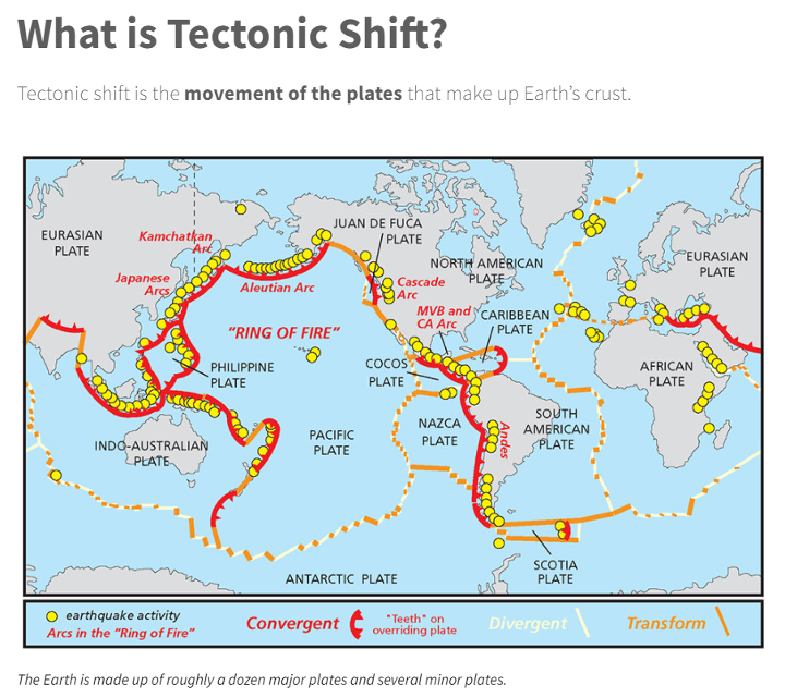
Ring of Fire
Image: National Ocean Service
The “Ring of Fire” map highlights earthquake activities around the world. As indicated in Table 5.1, earthquake or volcanic eruptions can change the shape of the geoid. Of course, they also can change the height of a mark due to crustal movement, which would typically be larger than the change in the geoid height. The amount of movement would be due to the size and magnitude of the event, but even small earthquakes could cause a change in the height of a mark located near the event. Earthquakes are occurring all over the world every day.
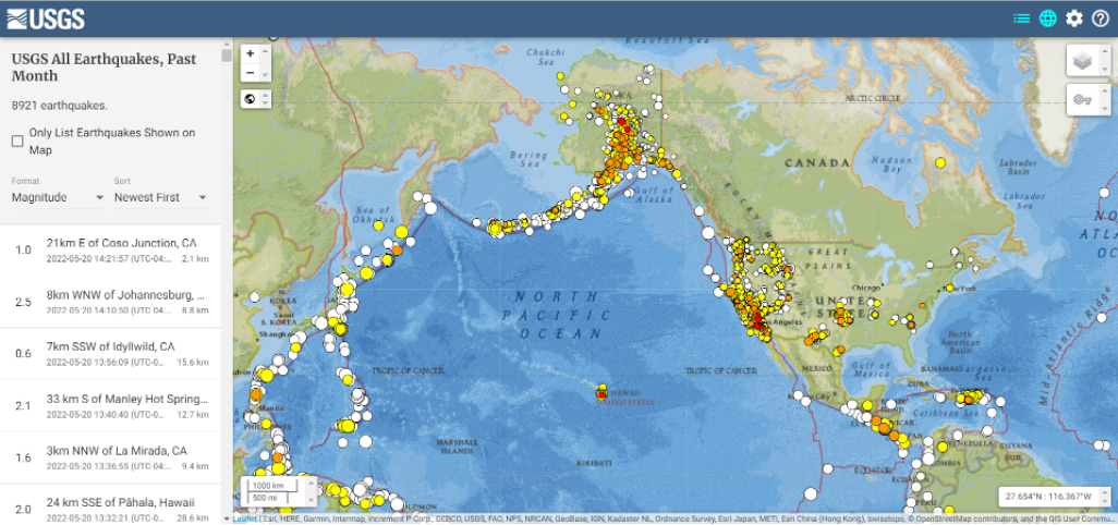
Earthquakes with large magnitudes are highlighted by news media outlets, but ones with smaller magnitude typically are not highlighted. The four figures below provide examples of earthquakes that have occurred over 30 days. This information can be obtained from the United States Geological Survey (USGS).
Earthquakes during the past 30 Days Date: May 20, 2022
Image: USGS
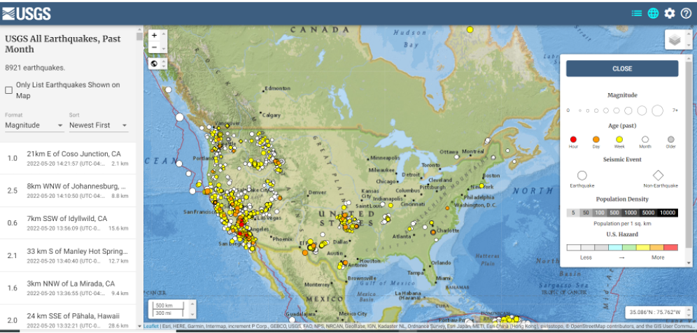
Earthquakes in the lower 48 during the past 30 days Date: May 20, 2022
Image: USGS
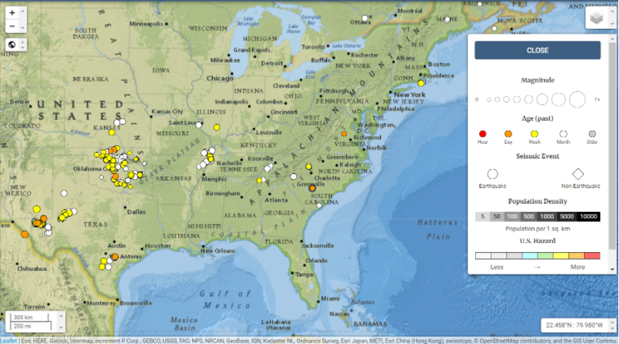
Earthquakes in eastern United States in the past 30 days Date: May 20, 2022
Image: USGS
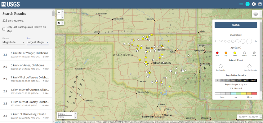
I found the large number of earthquakes that occurred in Oklahoma in just 30 days to be very interesting. This isn’t something that I thought occurred in the eastern region of the United States.
Earthquakes in Oklahoma during the past 30 days
Date: May 20, 2022
Image: USGS
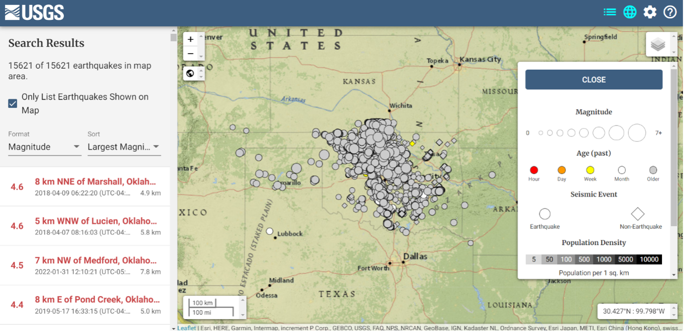
The image below depicts earthquakes that have occurred in Oklahoma in the past five years. They are fairly small in magnitude, but what is the cumulative effect on the geoid in the region, as well as changes to the orthometric heights of marks due to crustal moment in the region? This is why it is important for the new, modernized NSRS toimplement time-dependent coordinates.
Earthquakes in Oklahoma in the last 5 years Dates: 2017 to 2022
Image: USGS
To better understand the changes to the geoid, NGS performed a survey in Alaska to obtain geodetic data as part of its GeMS program. On May 12, 2022, Kevin Ahlgren, a geodesist at NGS, described in a webinar the observations collected and some of the results.
The presentation provided an overview of a field campaign performed in support of the GeMS program and a time-dependent geoid model. The campaign included static GNSS, relative gravity, and deflection of the vertical techniques on 50 stations in Alaska. The webinar was can be downloaded.
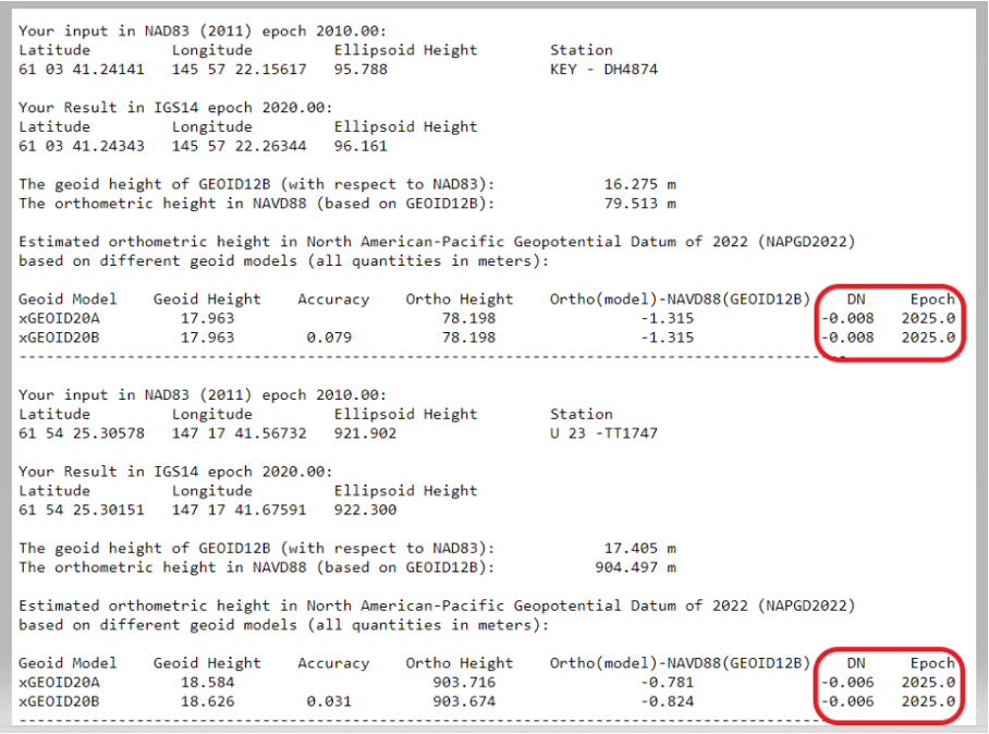
I encourage everyone to download the presentation. The change in the geoid due to geophysical drivers is small, but if the new, modernized NSRS is going to include time-dependent coordinates, then changes in the geoid must be accounted for. For demonstration purposes, NGS provides an example of the time-dependent geoid change in the xGEOID20 webtool. The box below, “xGEOID20 interactive computation output,” is an example of using this tool. The two stations are located in Alaska. As indicated in the output from the tool, the change in the geoid is 8 mm in five years. Again, NGS’s goal is to maintain geoid accuracy at the centimeter level (1 standard deviation) in both absolute and differential geoid undulations. These small changes can become significant over time.
xGEOID20 interactive computation output
Note: DN is the time-dependent geoid change computed between user inputted epoch (t) and t. (Image: NGS)
The last geoid change group that I’ll highlight has to do with the change in the gravity potential (W0) value that defines the model. The NOS NGS 64 Report states that the standing definition of the geoid, as adopted and used at NGS, is the following:
The geoid is the equipotential surface of the Earth’s gravity field which best fits, in a least squares sense, global mean sea level.
As stated in the NOS NGS 64 report, over a century of sea-level measurements imply that global mean sea level (GMSL) was rising at a rate of approximately 1.7 millimeters per year and was rising at a rate of 3.2 millimeters per year between 1993 and 2010 (IPCC, 2014). If NGS is going to define the geoid as theequipotential surface of the Earth’s gravity field that best fits, in a least squares sense, global mean sea level, then the geoid in the new, modernized NSRS must change when the GMSL exceeds a certain threshold.
Again, NGS’ goal is to maintain geoid accuracy at the centimeter level (1 standard deviation) in both absolute and differential geoid undulations. What this means is that as GMSL rises, the value of gravity potential which best fits to GMSL (called W0) will also change. In other words, the surface which was called “the geoid” and had W=W0in 2022 will no longer be the geoid. A new value of W0 (W0new) is chosen, and “the geoid” would now be the surface W=W0new.
So, what does this really mean to users? The NOS NGS 64 Report states on page 37:
“NGS and the Canadian Geodetic Survey have jointly adopted the value of 2.0 m^2/s^2 as the replacement threshold for a new geoid model (and new geopotential datum). This represents approximately 20 centimeters of GMSL (and thus geoid) rise. At the current rate of sea-level change of about +3 millimeters per year (IPCC, 2014), this means NGS expects to replace NAPGD2022 in approximately 60 to 70 years.”
Therefore, this should not be a major concern of users for a long time.
This column highlighted that orthometric heights in NAPGD2022 will be defined through ellipsoid heights and a geoid model, for instance GEOID2022; and therefore, changes in the geoid model will be very important to users estimating orthometric heights using GNSS. It briefly described the geophysical reasons for changes in the geoid that affect the orthometric height of a mark.
If NGS is going to meet the goal of maintaining geoid accuracy at 1 centimeter (1 standard deviation) in both absolute and differential geoid undulations, they will have to address changes in the geoid. The secular changes in the geoid, as indicated in Figure 13 in the NOS NGS 64 report, are very small, ranging from -1.25 mm/year to 1.5 mm/year. Once again, these are small changes to the geoid, but they will accumulate over time, and that is why NGS is including time-dependent coordinates in the new, modernized NSRS.
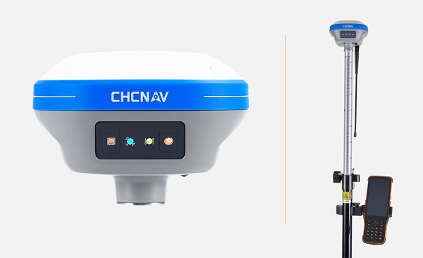
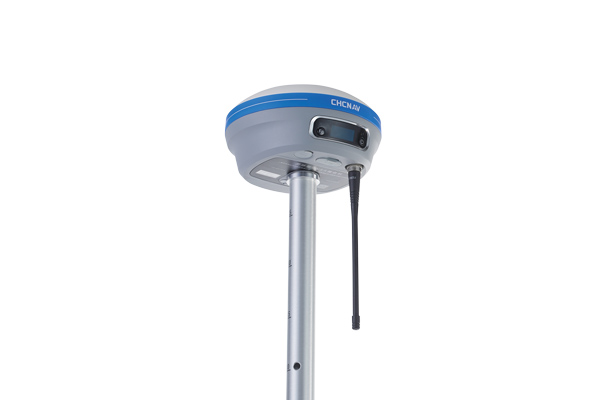
CHC Navigation (CHCNAV) has launched the i73+ pocket-sized GNSS receiver. The i73+ is a compact, powerful and versatile receiver with an integrated UHF modem that can be used either as a base station or rover. Powered by 624 GNSS channels and the latest iStar technology, the i73+ delivers survey-grade accuracy in all jobsite configurations.
“Building on the legacy of the i73 GNSS receiver, the new i73+ receiver is designed to maintain its proven compact and lightweight concept, but adds the ability to be operated as either an RTK base station or a rover,” said Rachel Wang, product manager, Surveying and Engineering Division, CHCNAV. “To enable this extra feature, we have built in the latest UHF modem technology, allowing the reception and transmission of RTK corrections without sacrificing receiver size and power consumption.”
Integrated Tx/Rx UHF modem extends capacity
The i73+ has a built-in transceiver radio module compatible with major radio protocols, making it a suitable portable built-in UHF base and rover kit with fewer accessories. The i73+ is a highly productive NTRIP rover when used with a handheld controller or tablet and connected to a GNSS RTK network via CHCNAV LandStar field software.
The integrated, advanced 624-channel GNSS technology takes advantage of GPS, GLONASS, Galileo and BeiDou, in particular the latest BeiDou 3 signal, and provides robust data quality at all times. The i73+ extends GNSS surveying capabilities while maintaining centimeter-level survey-grade accuracy.
The i73+ GNSS receiver. (Photo: CHCNAV)
Built-in IMU technology
With its inertial measurement unit (IMU) compensation ready in 3 seconds, the i73+ delivers 3-cm accuracy at up to 30º pole tilt, increasing point measurement efficiency by 20% and stakeout by 30%. Surveyors are able to extend their working boundary near trees, walls and buildings without the use of a total station or offset measurement tools.
The i73+ is the lightest and smallest receiver in its class, weighing only 0.73 kg including battery. It is almost 40% lighter than traditional GNSS receivers and easy to carry, use and operate without fatigue. The i73+ is packed with advanced technology, fits in hands and offers high productivity for GNSS surveys.
The i73+ includes a built-in UHF modem. (Photo: CHCNAV)
A roundup of recent products in the GNSS and inertial positioning industry from the May 2022 issue of GPS World magazine.
SURVEYING
Measurement Workflows
Field-to-office inspection with survey-grade accuracy
Photo: Trimble
Trimble Access field software now connects with Infotech’s Appia service to streamline the workflow from survey to construction. Aimed at the inspection process for civil infrastructure projects, the software provides high-accuracy measurement workflows for daily work reports and inspection reporting for engineering, construction and public agencies. By streamlining the connection between data collected by Trimble GNSS rovers and simultaneously syncing Trimble Access, Infotech Mobile Inspector and Infotech Appia, inspectors can now complete their daily work reports more efficiently in the field and reduce errors. With manual processes removed, inspectors can more accurately represent infrastructure assets.
For surveying, mapping and construction professionals
Photo: CHCNav
The i83 GNSS receiver is powered by a multi-band GNSS receiver, iStar technology, and a calibration-free, high-end inertial measurement unit (IMU) for faster and reliable field GNSS surveying. The third-generation high-gain antenna with advanced CHCNAV iStar algorithm improves GNSS satellite signal tracking efficiency by more than 30%. The i83 GNSS receiver features 1,408 GNSS channels for high performance across GPS, GLONASS, BeiDou, Galileo and QZSS constellations. Its onboard GNSS technology delivers centimeter-level positioning, maintains reliable fixed real-time kinematic (RTK) accuracy, and collects points faster than previous models, even in demanding conditions. The i83 receiver’s built-in IMU automatically compensates for pole tilt. In less than 5 seconds, the 200-Hz inertial module is initialized to ensure survey-grade accuracy over a pole-tilt range of up to 30 degrees. Productivity is dramatically increased, RTK usability greatly improved, and potential human error reduced, whether you are an engineer, site foreman or surveyor.
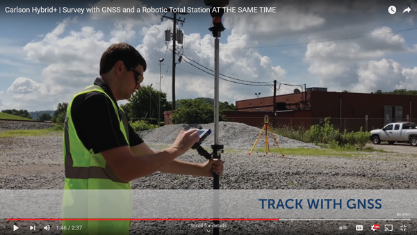
Simplifies surveying with both GPS and total station
Photo: Carlson Software
SurvPC Hybrid+ is a module for SurvCE version 6 software that enables surveying with mixed brands of GNSS receivers and total stations. SurvCE is a data-collection software package from Carlson Software. SurvPC Hybrid+ provides driver support for numerous devices, allowing the surveyor to interface with both types. Features include Follow Me, Smart Lock, Smart Staking, Cross Check, Backup Tracking, Hybrid-Resection, Auto-Localize, and Easy Setup Wizard.
SurPad 4.2 is designed to help surveyors work efficiently at all types of land surveying and road engineering projects in the field. It runs on eSurvey handhelds, Android smartphones and tablets, and third-party Android devices. It integrates with professional receiver control, point collection, stakeout, geographic information system (GIS) data collection, road measurement, road design, cross-section measurement and railway stakeout. SurPad 4.2 provides multiple operation and communication systems, has mapping and CAD functions, and has a coordinate system. It also includes a survey mode encompassing topo, control, quick point and COGO civil engineering programs.
The Leica AP20 AutoPole provides tilt compensation, automatic pole-height readings and unique target identification for automated total stations. It combines an intelligent sensor module with the AP Reflector Pole and operates with existing Leica Geosystems’ automated total stations to create a solution for autonomous workflows. Tilt compensation decreases measurement time and increases flexibility and safety on site by enabling measurement of points in inaccessible or risky locations. By updating the pole height automatically in the field software, the system ensures that the height on record is always correct.
INSITE Data Reviewer moves geospatial data validation to the cloud, giving key stakeholders the ability to collaborate in real time. The third module in the INSITE Lifecycle suite of products, INSITE Data Reviewer provides reviewers real-time access to aerial imagery, lidar data and geographic information system (GIS) layers via the cloud to standardize quality control. This increases data validation speed and reduces costs of geospatial projects. The INSITE Lifecycle suite combines Project Tracker, Data Delivery and Data Reviewer modules through which users can see their projects executed on a map, from data acquisition through processing.
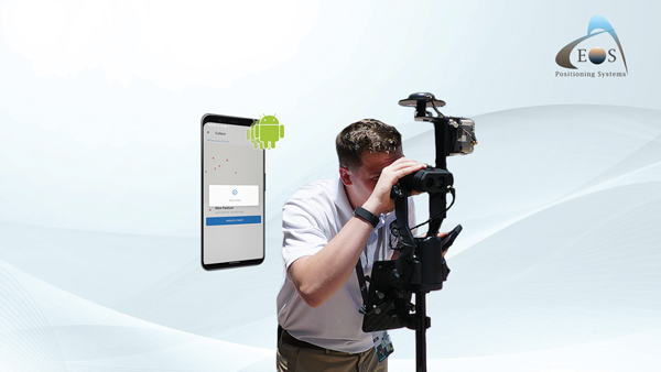
Eos Laser Mapping for ArcGIS is now available on Android devices. It allows mobile crews to capture high-accuracy laser offsets directly into ArcGIS Field Maps with Arrow Series GNSS receivers. The solution combines technology from geographic information system (GIS) provider Esri, laser rangefinders from Laser Tech, and Eos’ own Arrow Series GNSS receivers. The release supports three workflows: standard laser offset (range-azimuth), range-range (range-intersect) and range-backsight (a total station-like method).
The MV60 micro-electromechanical system (MEMS) accelerometer delivers high performance and reliability in a small, rugged and low-cost package. The MV60 measures the acceleration experienced by an object during movement and is designed for use in inertial measurement units and navigation systems deployed on land, air and sea vehicles to measure velocity. It has a compact footprint of 1.2 square inches and shock survivability of up to 5,000 g. It also offers bandwidth of greater than 300 Hz — important for environmentally demanding missions.
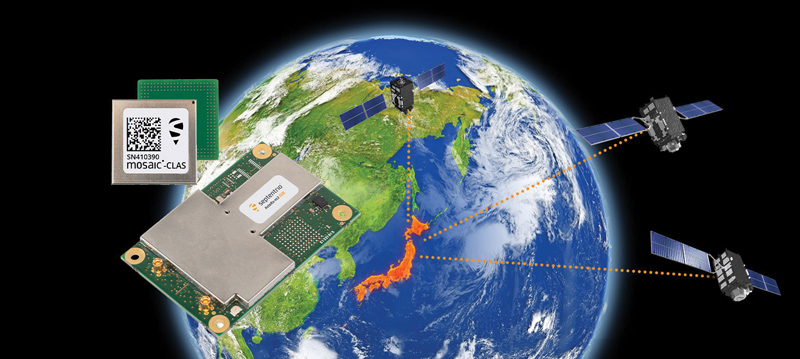
Receivers support Japan’s cm-level augmentation service
Photo: Septentrio
Three multi-frequency GNSS receivers now support the Centimeter-Level Augmentation Service (CLAS), receiving the L6 signal that transmits high-accuracy corrections from Japan’s QZSS constellation. The mosaic-CLAS receiver is in a small form-factor suitable for high-volume industrial applications. The AsteRx-m3 CLAS OEM board combines PPP-RTK CLAS with dual-antenna heading functionality. The AsteRx SB3 CLAS features a ruggedized IP68 enclosure to protect it in harsh environments.
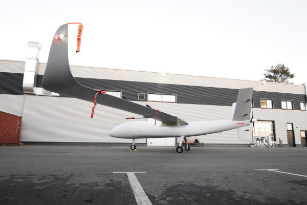
The S1-V300 medium-altitude long-endurance (MALE) unmanned aerial system (UAS) prototype is based on the Saker MALE UAS design that achieved operational capability in 2020. The prototype features a new design and a more powerful heavy fuel engine with 260 HP, offering greater speed, payload and endurance of 28 hours with a range of 4,020 km. The aircraft features unique UAVOS avionics solutions and a redundant flight control system that will enable complex missions, including overland and maritime intelligence, surveillance and reconnaissance (ISR) missions. The improved S1-V300 prototype is equipped with both line-of-sight and beyond-visual-line-of-sight (BVLOS) datalink systems for over-the-horizon operations. It can be integrated with multiple ISR sensors, including electro-optical infrared cameras and a synthetic aperture radar that offers all-weather, day/night performance for a wide-area search capability.
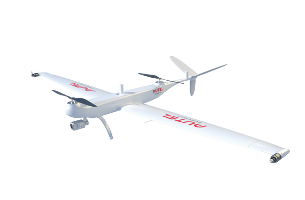
Dragonfish Lite and Pro now available in United States
Photo: Autel Robotics
The rugged Dragonfish UAVs are capable of vertical takeoff and landing (VTOL) with both multi-rotor and winged flight, with an endurance of up to 180 minutes. They are suitable for professional applications such as energy, mining, defense and surveillance. Maximum winged flight speed is 30 m/s (108 km/h, 67 mph), and maximum video transmission range is 30 km (18.6 miles) with a base station. The aircraft can make a smart decision to either land or return to base in case of issues such as loss of GPS signal, loss of operator communications, or low battery power. The tilt-rotor system will automatically transition to multi-rotor mode if adverse conditions cause fixed-winged flight to stall or become unsustainable. The Dragonfish battery, barometer, positioning system, compass and inertial measurement unit all have backup modules to ensure flight safety.
The SureCam connected dash camera system now features a method for capturing video footage from SureCam cameras using Geotab’s telematics device and rule-based system. This results in a seamless display of video within the MyGeotab platform. The enhanced SureCam fleet video solution leverages Geotab’s numerous data-based rules, such as improper seat belt usage and speeding. It also uses G-force triggered alerts that detect unsafe driving behaviors and automatically captures video footage that can be reviewed later. A new Video Request feature in GeoTab enables fleet managers to preview and download additional SureCam video, enabling them to investigate call-ins and other minor incidents that may not have been triggered by an event-based rule.
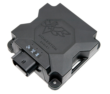
Momentum IoT’s long-life Eagle 1 tracker works without external power for more than six months after a single charge. The device switches on-the-fly between narrowband internet of things (NB-IoT) and LTE Cat-M. The Eagle 1 leverages Telit’s dual-mode ME310G1 module, which delivers low power consumption in a small footprint. The Eagle 1 detects movement with a built-in accelerometer. Using movement and signals from its GPS receiver to determine vehicle trip starts and stops, the device can go into hibernation mode during periods when the vehicle is not in use, further reducing power consumption. Applications include garbage and storage bins, portable toilets, roll-off containers, message-boards, coolers, and other equipment typically stationed in non-powered, remote places for extended periods.
Tersus GNSS has released a white paper on ExtremeRTK Technology. According to the company, the white paper demonstrates how ExtremeRTK Technology delivers excellent performance in all manner of surveying scenarios and describes its impressive compensated results when performing tilt surveys — even tilt at angles greater than 90°.
As a professional real-time kinematic (RTK) developer and manufacturer, Tersus believes the stability and accuracy of RTK are the cornerstones of RTK measurement.
According to the paper, “ExtremeRTK integrates the receiver’s hardware, high-precision baseband IC [integrated circuit], RTK engine, GNSS/INS coupling algorithm, etc. It enables unprecedented performance stability in challenging environments and prevents occurrences of occasional RTK positioning outliers.”
Tersus starts from scratch — engineering each element from its foundation in the physics of GNSS. From signal capture and baseband tracking engine to position-velocity-time (PVT) results and the overall algorithm of RTK, Tersus completes all algorithm logic independently.
The white paper discusses:
signal tracking and multipath mitigation capabilities
fix speed in open-sky and challenging environments
accuracy when performing RTK control/detail point/continuous point surveys
GNSS/INS tilt compensation.
Test results described indicate the remarkable performance of ExtremeRTK technology in RTK initialization, accuracy and tilt compensation. Based on ExtremeRTK, Tersus will continue to invest in the further development of RTK receivers by adding photogrammetry, laser scanning and more.
Meanwhile, Tersus will also focus research and development on professional industry software, the integration of resources in data management, and big-data applications so it can provide users with additional professional services.
The U.S. Army Corps of Engineers, St. Louis District, has contracted with Aero-Graphics for photogrammetric and lidar surveying and mapping for the next five years. Aero-Graphics is a 56-year-old geospatial services company headquartered in Salt Lake City, Utah.
The $16 million contract is an indefinite delivery indefinite quantity (IDIQ), firm-fixed-price contract.
The services requested are for photogrammetric mapping and related surveys, as well as the preparation of maps for advance planning, design, real property, construction, land-use and land-type monitoring, and analysis for various projects.
“Being awarded the USACE St. Louis District contract is an honor, especially because we will support the Center of Expertise for Photogrammetric Mapping,” said Casey Francis, Aero-Graphics co-president. “Their focus on geospatial rapid response and technical proficiency is directly aligned with Aero-Graphics’ unique process. Our entire team looks forward to supporting this exciting contract.”
Francis added, “Our mantra is ‘agile responses to ever-changing environments.’ We look forward to demonstrating our unique abilities to the St. Louis District, enabling them to accomplish their mission of securing our nation, energizing our economy, and reducing disaster risk.”
New business development specialist hired
Angela Arriaga
In other company news, Aero-Graphics appointed Angela Arriaga as its new business development specialist. In her role, Arriaga will be responsible for expanding the company’s client base.
Arriaga comes to Aero-Graphics with more than 10 years of experience in geospatial, aviation, processing and surveying. “Angela has a strong background in operations management in lidar and ortho imagery,” Francis said.
“Aero-Graphics has always been a staple in this industry with an outstanding reputation and a commitment to excellence,” Arriaga said. “It’s exciting to be a part of this incredible team. The leadership is fully committed to professionalism, passion and enthusiasm for the work. I am looking forward to help continue its expansion and the success of our customers.”
Mason and Dixon were pioneers in bringing geodetic astronomy to the American colonies. Through the efforts of the Mason and Dixon Line Preservation Partnership, we can promote this scientific contribution along with the placement of the boundary stones.
Ask surveyors why they became engaged in the profession and why they had continued with it, most will centralize on one aspect: working outside. A career that allowed them to work outside in various environments, solving problems, and being part of a solution is typically the main answer they give.
Depending on the task at hand, a day in the field surveying can take one to several places, including urban/suburban neighborhoods, construction sites, and agricultural/wooded farmland.
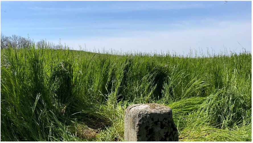
View from Mason Dixon Stone #95 looking toward Maryland. (Image: Tim Burch)
My entry into surveying was no different. From residential sites, condominium surveys, boundary and topographic surveys, and construction layout, my early years in surveying covered a lot of territory. While my career eventually took me out of the field and into an office managerial role, and now into leading a professional association, it does not erase the roots of one’s surveying knowledge and experience. Opportunities to be part of the field exercises of a survey, especially a boundary survey, are typically rare and subject to time constraints.
Having spent all my life in the flat topography of Illinois and surrounded by farm fields and urban sprawl, the ability to see for miles over the various horizons was the norm. Coupling these conditions with the Public Land Survey System (PLSS) and use of GNSS technology, it makes for a great environment for the professional surveyor to go about his or her work.
However, the United States covers many areas and contains distinct types of terrain, ecosystems and demographic groups that provide challenges to the surveyor. While I assumed moving from Illinois to the mid-Atlantic region would require adaptation, an opportunity to help retrace and inventory a significant part of American history provided me with an eye-opening experience. It also helped me appreciate the legacy of our surveying forefathers.
A small title dispute
Even in the 17th and 18th centuries, disagreeing title descriptions to common lands was an issue. Reviewing two conflicting legal descriptions describing adjacent land boundaries is the basis of this survey exercise, and thus began a symbolic establishment of a famous boundary line that would lead to political and demographic ramifications in later years.
Here is the situation:
1632: King Charles I grants to Cecilius Calvert (second Lord Baltimore), a royal charter for establishing a new colony north of Virginia to a point “which lieth under the Fortieth degree of north latitude” and westward to the source of the Potomac.
1681: King Charles II (eldest son of Charles I) grants William Penn a royal charter of land between 43° N and a line extending westward from “a Circle drawn at twelve miles distance from New Castle…” to “the beginning of the fortieth degree….”
1682: King Charles II grants to William Penn an additional grant in the Delaware peninsula, which Lord Baltimore claimed.
1685: King Charles II directed his Board of Trade and Plantations to issue an edict ordering that territory to be divide equally, the western half going to Baltimore. This order endorsed Calvert’s claim of a boundary line being 19 miles to the north and providing him claim to Philadelphia. Part of the edict placed a burden on Calvert of providing a survey to authenticate the claim, but the survey was not completed. The boundary would eventually be established 19 miles to the south.
1731-1732: Charles Calvert, the fifth Lord Baltimore, petitioned King George II for help in demarcating the final boundary. He agreed on the final boundaries; however, a commission created to study the legal claims failed to deliver instructions in which a survey would be based upon. Calvert disputed its interpretation and refused to implement the arrangements.
1730s: Ongoing conflict over the disputed land claimed by both people from Pennsylvania and Maryland resulted in Cresap’s War, named after the land agent, Thomas Cresap, hired by Calvert to settle new development. In 1736, Cresap was accused of murder, arrested by Pennsylvania officials and his housed burned was burned down.
1750: After years of bitter controversy, British Lord Chancellor Hardwicke ruled that the southern boundary of Pennsylvania should be a line running westward from the point at which the line dividing the Delaware peninsula was tangential to a circle with a radius of 12 miles from the center of Newcastle.
After 100+ years of boundary disputes and deadly confrontations, in 1760 Frederick Calvert was directed by the English monarch to accept the terms of the 1732 treaty.
Penn-Calvert Land Grant Agreement. (Image: National Archives)
The unfilled challenge, however, was to commission a survey to establish the terms of the agreed-upon boundary. Given that the final location of the Pennsylvania/Maryland border was geographically based (approximate latitude of N 39°43’20”), the surveyors chosen to establish this line would have to be knowledgeable in such calculations.
Finding qualified surveyors in the colonies turned into a bigger challenge than first considered, so the monarchy assigned two surveyors from the Royal Society (full name: Royal Society of London for Improving Natural Knowledge). Enter Jeremiah Dixon (surveyor) and Charles Mason (astronomer) — the field party charged with tackling this monumental deed.
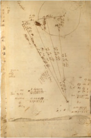
The survey calculations of Charles Mason. (Image: National Archives)
We know them by name for the lines they established in fulfilling the requirements of the boundary agreement, but how they accomplished their task remains a mystery to most. Previous exercises using geographical position determination was used in the sailing and shipping industries with lesser degrees of accuracy. This assignment would require higher levels of accuracy and precision, hence the reason for calling upon Dixon and Mason for the task.
By using geodetic astronomy, they were able to determine accurate (for the period) geographical positions of latitude. Geodetic astronomy is the art and science for determining, by astronomical observations, the positions of points on the earth and the azimuths of the geodetic lines connecting such points. It relies on spherical astronomy, using calculations and techniques developed by the Greeks in the second century A.D.
Besides the knowledge of performing the necessary calculations, the duo would also need to possess instruments to gather the accurate astronomical information. The survey of the agreed-upon line was to be established upon a constant line of latitude. The survey procedures would require turning angles (azimuths) from their meridian westwardly with accuracy not yet utilized in the New World.
Both instruments used for the project were built by John Bird, a well-respected instrument maker in London. The equipment consisted of a zenith sector, capable of measuring to two arc seconds. No field azimuth instrument of this accuracy existed in that era. They also brought a converted telescope/level set up for surveying purposes. This transit has no divided horizontal “plate,” only a tangent screw for slow azimuth motion.
In addition to the instruments and astronomical tables from Greenwich and Paris, the duo relied on a highly precise clock for marking time by the second, which was quite advanced for the period.
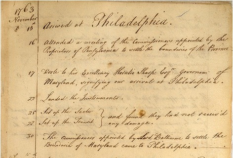
Dixon and Mason spent the better part of 1766-67 establishing the agreed-upon line using astronomy via the Bird instruments and taking copious notes documenting their calculations and survey conditions.
Field notes from Jeremiah Dixon. (Image: National Archives)
The markers set along the way —stone monuments chiseled back in England with demarcations — were quite accurately established despite the primitive nature of equipment and methodology for the survey. Mason and Dixon laid out the 233-mile long “West Line” in short segments, following the latitude arc of approximately N39°43’20” for 233 miles westward.
Old line versus new technology
In 2020, the Maryland Geological Survey (MGS) and the Pennsylvania Historical & Museum Commission (PHMC), members of the Mason and Dixon Line Preservation Partnership, began a new initiative to inventory these historic markers and submit them for inclusion into the National Registry. If accepted, the monuments will be part of a program established to help protect and preserve these physical boundary markers that define the boundary between the two states.
Part of the inventory has been the recovery and position confirmation by volunteer surveyors from the Maryland Society of Surveyors (MSS) and the Pennsylvania Society of Land Surveyors (PSLS). Using a geographic information system (GIS) app designed and implemented by the Maryland Geological Survey (MGS), volunteer retracers capture significant attributes about each monument.
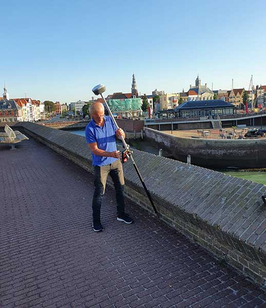
While reestablishing the latitude/longitude of the recovered monuments with a smartphone or handheld GPS receiver is sufficient, several volunteers have used high-accuracy surveying equipment to determine a monument’s position.
Incredibly, the variation in the location of a given monument is well within reasonable tolerances from the originally intended installation. Also, because of GNSS technology, we now know more about continental drift. Because of this additional knowledge, 250+ years of tectonic plate movement should be considered when making these positional comparisons.
It should be noted that these monuments are a critical component of the boundary between states, and therefore must be considered senior to many other survey corners set after them. We cannot get lost in the sentimental aspect of recovering the monuments and not acknowledge the fact these points are the gospel when it comes to defining these state boundaries.
A Midwesterner in a ‘foreign’ land
My surveying career, as noted above, was solely in a state that is 200 years old, based upon the PLSS, and does not carry the history of the Mason-Dixon era of line establishment. So, when I was presented with the opportunity to join fellow surveying professionals from Maryland and Pennsylvania in recovering Mason-Dixon monuments for the inventory, I found it an easy event to join.
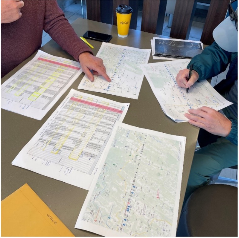
The planned meeting spot was a local fast food place at 8 a.m. on a sunny Saturday. Being it was in a small town, there were several groups meeting for their normal Saturday coffee klatches. Hearing a group mention “surveying,” I found my opening to identify myself as a fellow surveyor. After opening pleasantries, we settled into a game plan for recovering the targeted monuments for the day.
Planning a day of stone monument recovery along the Mason-Dixon line. (Photo: Tim Burch)
We settled on our assignments and enthusiastically went about our way. My partner for the day was Eric Gladhill, a Pennsylvania professional surveyor and veteran of Mason-Dixon monument retracement. In addition to his volunteer work, he has also authored several articles and a book on his surveying experiences, so it was quickly evident that we were in for a good day.
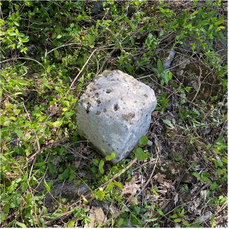
The first monument was not difficult to get to, and seeing it nearly brought a tear to my eye. Here before me was my first sighting of a Mason-Dixon monument stone, and it was simply amazing. Standing there admiring this 250+ year old stone, hand cut and carved in England and brought here by ship to be specifically placed on this line, I could not help but realize the importance of this monument.
This line, and these stones, were the culmination of two land grants that disagreed with each other more than 400 years ago. We were standing in the same location as a large survey party once did, where they observed the stars to determine an accurate position and directed axmen to clear the untamed forest to establish this important line. While it was a warm and sunny day, it gave me a chill to know we were following in the footsteps of our surveying forefathers.
Mason Dixon Stone #98 – My first recovery! (Photo: Tim Burch)
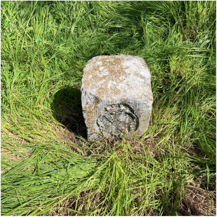
We continued our way and recovered six more monuments, including a crown stone. Crown stones were placed at 5-mile intervals. The detail in the carvings for most of the monuments was noticeably clear, and is a testament to the craftsmanship of the era’s stonecutters.
Mason Dixon Stone #95, a crown stone. (Photo: Tim Burch)
While locating these historic monuments, were felt we were standing on hallowed ground. The location of this line was important enough that people, both indigenous and settlers, fought for the right to build their lives there.
This was also a line that would be the site of many battles during the Civil War. Observing these monuments drove home the fact that surveyors play important roles in establishing land ownership both today as well as almost 300 years ago.
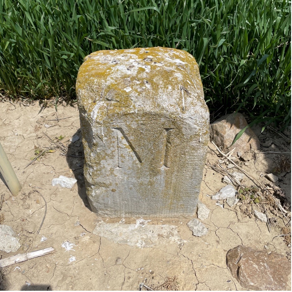
Mason Dixon Stone #93, a Maryland side marking. (Photo: Tim Burch)
Mason and Dixon were pioneers in bringing geodetic astronomy to the American colonies. Their work has provided inspiration for future generations of geospatial professionals, yet most of the public does not know about that portion of their contribution. Hopefully, through the efforts of the “Mason and Dixon Line Preservation Partnership,” we can promote this scientific contribution of Mason and Dixon along with the placement of the boundary stones.
My heartfelt thanks go out to Eric along with Wayne Aubertin and Rob Kundrick (Appalachian Chapter of the Maryland Society of Surveyors) for allowing me to join them for this task. They gave me a chance to be a true surveyor again and connect the past with the future.


![Figure 32: Geoid rate over CONUS based on the GSFC mascon model [mm/yr] (Image: NOAA)](https://stage.globalpositioningnews.com/wp-content/uploads/2022/05/Geoid-rate-CONUS.jpg)
![Figure 33: Geoid rate over Alaska from GSFC mascon model [mm/yr] (Image: NOAA)](https://stage.globalpositioningnews.com/wp-content/uploads/2022/05/geoid-rate-alaska.jpg)