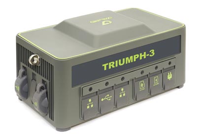
Javad GNSS has launched the TRIUMPH-3 receiver for surveyors and geodesists. It is capable of efficient tracking even in difficult conditions. It can track all current signals and is ready for any future satellites.
TRIUMPH-3 is designed to operate as a base together with TRIUMPH-LS and TRIUMPH-LS Plus to efficiently accomplish any geodetic job. Its real-time kinematic (RTK) system communicates via integrated UHF, 4G/LTE, Wi-Fi and Bluetooth channels, and eliminates the need to subscribe to a real-time network for corrections.
The new powerful and reliable receiver for high-precision navigation systems is based on the Javad GNSS 874-channel chip. It is equipped with an internal 4G/LTE/3G card and secure and accessible microSD and microSIM cards. It also supports “lift & tilt” technology.
The TRIUMPH-3 receiver can operate as a receiver for post-processing, as a continuously operating reference station (CORS) or portable base station for real-time kinematic (RTK) applications, and as a scientific station collecting information for individual studies, such as ionospheric monitoring.
Features include:
UHF 1 W Transceiver
4G/LTE module
Wi-Fi 5 GHz and 2.4 GHz (802.11 a, b, g, n, d, e, i)
Dual-mode Bluetooth and Bluetooth LE
Full-duplex 10BASE-T/100BASE-TX Ethernet port
High Speed USB 2.0 Host (480 Mbps)
High Speed USB 2.0 Device (480 Mbps)
High Capacity microSD Card (microSDHC) up to 128GB Class 1 O;
The Earth Archive Initiative is an unprecedented scientific effort to create a digital twin of the entire surface of the Earth – and everything on it.
By scanning the planet’s land surface with very high-resolution lidar, the Earth Archive will create a true three-dimensional digital twin of our world — an open source, digital record of the Earth that will reflect the landscape exactly as it was at the time of scanning.
The geospatial data captured will serve as the baseline for understanding and exploring our world.
A virtual conference, billed as the “Chapter I : The Amazon,” takes place June 15-16, and will provide updates on the unique project from academics, non-government organizations, technology providers and the public. Registration is free.
The Amazon Basin is the first region chosen for scanning and the focus of the conference. “While our scope is the entire planet, we’ve tasked ourselves with first scanning areas that are not only most susceptible to change, but also deep in value for understanding our past,” a project spokesperson explained.
“The 2021 inaugural Earth Archive Congress is centered on our initial campaign to scan the entire Amazon Basin. The Amazon rainforest plays a monumental role in the Earth’s climate, has an incredibly rich Indigenous history, and boasts a remarkable level of ecological diversity — but is vanishing before our eyes.
“With the ability to digitally preserve landscapes at any moment in time, very high resolution lidar can enhance archaeological, anthropological, and conservation studies and provide needed information to help advance sustainable development, as well as provide us with more groundbreaking revelations of the Amazon’s astounding past.”
Registration at the Earth Archive Virtual Congress is complimentary.
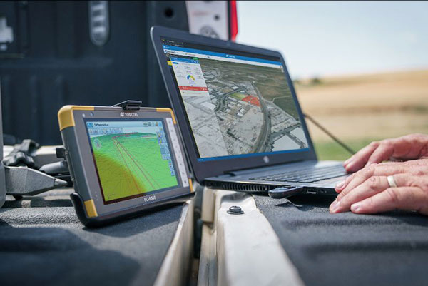
Survey and construction software suite MAGNET7 is now available from Topcon, using cloud-based connectivity to streamline workflows through GNSS receivers and other equipment.
Photo: Topcon
Survey and construction software suite MAGNET 7 is now available from Topcon Positioning Group.
MAGNET7 uses cloud-based connectivity to streamline workflows through GNSS receivers, total stations and other positioning tools and instruments. It addresses common needs to increase productivity, efficiency and profitability levels across the job site.
The software is also designed to improve accuracy while efficiently managing data and collaboration — in real time — with the project team.
Enhancements in the MAGNET7 field version improve 3D model support, reporting and interactivity in working directly on a visual map. Also improved is data handling for large and complex 3D projects.
Productivity features include an ability to connect to the newest version of the Sitelink3D job-site monitoring and management system. This enables office personnel to send machine models via the web portal directly to machines on site.
The new connection also allows access to the Haul Truck app, which dramatically improves efficiency in the mass-haul environment by sending real-time data — including haul volumes and truck locations — directly to the master schedule.
MAGNET7 provides new capability for calculating the International Roughness Index (IRI), a valuable indicator for resurfacing projects. The IRI data exports directly to ProVAL formats, commonly used in the paving industry, to report and validate road-surface smoothness against government guidelines.
Also provided are enhanced terrain-modeling capabilities for surveyors and an overall increase in file-type capability.
Addressing COVID-19
COVID-19-related demands placed on construction and survey professionals underscore the need for comprehensive, integrated software solutions to meet those challenges head on, according to Alok Srivastava, senior director, product management.
“The push to ramp up production levels and increase efficiency, while operating profitably, has never been greater,” Srivastava said. “Our suite — made up of field software, cloud services, tightly integrated office software and third-party integrations — is a key component of our digital ecosystem, all designed to enhance productivity in the field while helping the office efficiently manage the project dataset. It does so by tapping the power of integrated solutions to provide end-to-end workflows, superior data exchange and a far better level of collaboration.
“We’ve long recognized that many of the basic needs and challenges of today’s survey and construction disciplines are similar. With that in mind, this solution provides compatible, comprehensive, connected answers to many of those shared issues.”
“The need for digital connectivity, both on site and between the office and the job site, has never been greater,” Srivastava said. “With the continued push toward digitization in all facets of their jobs, today’s construction and survey professionals regularly risk loss of efficiency — and the financial costs associated with it — due to issues of incompatibility between equipment and systems. This upgrade of the MAGNET suite of productivity solutions takes connected field and office management to a new level, making the long sought-after ‘end-to-end workflow’ a reality while helping projects stay on schedule and under budget.”
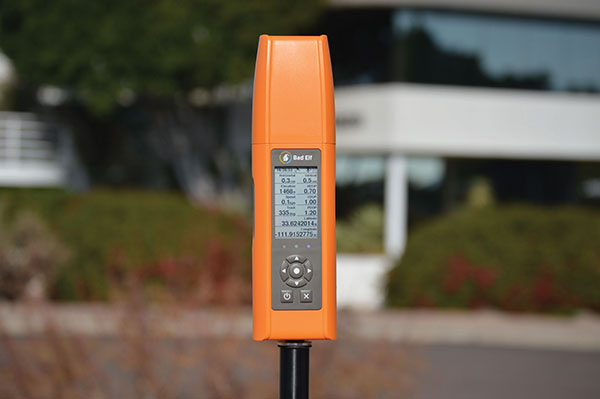
The new display can be easily read in sunlight. (Photo: Bad Elf)
When survey receiver maker Bad Elf set out to make its new Flex device, they knew they had to make the battery last longer. But the device’s screen was eating up power, shortening surveyors’ time in the field.
“As we were building out the idea for Bad Elf Flex, we knew surveyors wanted four things: sunlight readability, a backlight for night visibility, ability to read the screen from a distance of one meter, and a long battery life,” explained Larry Fox, vice president of marketing and business development at Bad Elf. “We found many different display types, but they were all power hungry and not a great fit for surveyors who need to be in the field for a full day.”
After researching options, Bad Elf determined that transflective display technology could offer the power savings and visibility required. The Flex uses Azumo’s reflective LCD technology — a sheet of plastic the width of a human hair. Adhered to the device’s screen stack, it uses a front light instead of a power-hungry back light. The change allows for 90% energy savings.
The new Flex is popular with Bad Elf customers. “They’re getting the kind of quality they want in a high-end receiver, with the affordability they desire. It’s easy to see in the sun, and compatible with a wide variety of apps,” Fox said.
Many have debated how the surveying profession has morphed into something less than what our predecessors would have called surveying.
In earlier times, the surveyor was an honored figure in the community and held in high regard, like the local doctor and clergy. Surveyors had the final word on boundaries and the limits of a family’s land holdings, so they were treated like royalty.
Measuring devices were simple yet complicated enough for only the trained person to understand how boundary lines were determined. Surveyors during those times depended much on natural monumentation and terrestrial features; these items made for solid and definable boundaries. Measurements along these features were to be completed only by surveyors and their means of determining distances.
Much has changed since those centuries past, including the reputation of the surveying profession. No longer are we mentioned in the same breath as doctors, clergy and lawyers. Even engineers are seen as “more professional” than surveyors. Many have debated how the surveying profession has been degraded from the noble status it once enjoyed and morphed into something less than what our predecessors would call surveying.
There are many layers to each of the previously described professions, but they all have several things in common: each one relies on data collection, analysis, and professional opinion. Each of these steps requires a specific skill set that includes education and experience. Nowhere in this process does it allow for advancing technology to completely replace any of these steps.
The evolution of technology and associated tools may help improve the profession, but it will not replace the knowledge necessary to be considered a true professional. Data collection within most professions is the biggest beneficiary of technology; surveying is a testament to these advancements. The breakdown, however, is the availability of the technology to the public and turning non-practitioners into low budget pseudo-surveyors.
Here is the abridged version of the definition of “professional” according to the Merriam-Webster Dictionary Online:
professional (adjective)
: of, relating to, or characteristic of a profession
: engaged in one of the learned professions
: characterized by or conforming to the technical or ethical standards of a profession professional (noun)
: one who is professional
: one who engages in a pursuit or activity professionally
Similar professions have several examples of how the collection of data is a separate process and experience level from its analysis. Consider the following:
MRI technicians train for their jobs through education, interning and experience. They know how to place patients within the equipment, shield them, apply the rays, and produce the scans as required by their job description. In simple terms, they are data collectors of patients’ medical conditions. Technicians do not analyze the scans nor offer any opinion on the prognoses of the patients. They are, however, relied upon to obtain the proper scans correctly and efficiently for review by doctors.
Staff accountants or clerks are typically charged with data entry, maintaining ledgers and journals, and verifying data/entry accuracies. Often, clerks organize invoices, statements, and other receivables for input into clients’ accounts. Much of the work for this position is electronic and relies on the employees to be savvy with spreadsheets and able to import various data formats and spot suspect data. Once this work is completed, it become the responsibility of certified public accountants (CPAs) to review and certify the information. The key role here, however, is the accurate compilation of the accounting data.
Paralegals play a key role in doing the heavy lifting of data collection for lawyers. Paralegals perform client and case research, interview witnesses, handle discovery of case information, and draft many of the documents needed by lawyers. They are tasked with assembling exhibits, delivering and filing necessary court documents, and helping with trial preparation. While they cannot express legal opinions on any case matter, it is the paralegals’ work that lawyers use to develop case strategies. Once again, the data collection is the key to the success of the lawyers’ work.
Professional surveyors are no different from doctors, accountants, and lawyers in these examples. They rely on data collection obtained by experienced staff trained to operate sophisticated instruments and data collectors.
Field technicians often serve as surveyors’ eyes, so specific training is necessary to ensure that they can accurately locate the required information. Technicians, however, cannot offer legal opinions on the location of land and parcel boundaries.
This function is solely on the shoulders of land surveyors, who are licensed specifically in that jurisdiction to apply legal principles and case law to boundary issues.
There is one in every crowd — the North Carolina lawsuit
For those who are not paying attention, we are solidly in the 21st century and fully engulfed in the proliferation of geospatial data. Surveyors remain at the forefront of these technological advances with a plethora of tools and techniques being introduced on a regular basis.
These tools and associated software are much advanced compared to their earlier surveying instrument counterparts, but through extensive programming and easy-to-use interfaces, this equipment may seem simple to use to the layperson. The elder surveying generation likes to refer to newer technicians as button pushers, because the users perform no true calculations.
Yes, there are necessary checks and balances even with the new equipment, but the knowledge to operate these instruments is user-friendly and intuitive. So what happens when the technology is used by someone who is not a surveyor?
Among the hazards of making these newer tools and software widely available is how they are used by the non-professional public. As many surveyors have already read about in the news and social media, a UAV operator in North Carolina has filed suit against the NC Board of Examiners for Engineers and Surveyors.
The board previously ordered the operator to discontinue his UAV flights that engaged in mapping, surveying and photogrammetry services. The operator had been providing images to realtors and homeowners that depicted graphical lines representing property lines, but also included a disclaimer that the product was not intended for surveying purposes. The board ruled he was surveying without a license. The operator is now suing the board and accusing them of violating his First Amendment rights of free speech.
This case is a high-tech example of what surveyors have faced in the past with overzealous owners of metal detectors. Many instances of low-budget outfits and even fence installers have been brought before state licensing boards because they misrepresented surveying services.
It should also be noted that survey field crews who use their equipment during off hours to help family or friends with property location without their licensed supervisor’s knowledge face the same consequences. While the “corner finders” are somewhat harmless and get a slap on the wrist from licensing boards, it is the high-tech offenders who are creating much of the harm to the public.
These situations with unlicensed surveying practices have greatly increased simply because of the available technology and low cost of entry. While GNSS receivers, robotic total stations, and associated data collectors are still quite expensive, new remote-sensing applications are being produced using consumer-grade equipment and advancing software. As technology continues to increase based upon miniaturization and capability, the costs also continue to decrease based upon volume of sales.
Leading the charge into non-licensed use of new technology is the UAV and the new standard use of GPS technology within its guidance system of reasonably priced units. Hobby planes and helicopters have been around for years but required lots of skill and space to fly and were quite expensive. The invention of the multi-rotor UAV with integrated GPS has created an easy-to-fly vehicle with lots of capability.
Couple this new vehicle with a high-resolution camera for photos and video; now it allows amateurs to be aerial cinematographers. Image storage space is not an issue due to increased SD card capacity and speed.
A well-built UAV with all these capabilities is now very affordable and available everywhere. This revolution has led to larger format platforms with more rotors and heavier payloads for more sophisticated cameras and sensors. Once you have the photos and video, now you must do something with them.
The advancement of software technology for processing photos, video, and remote sensing modules has become the hottest ticket in site modeling. The combination of the UAV’s capability and the software’s output enables trained pilots and software technicians to provide orthometric-based imagery. This imagery was previously completed by airplanes and cameras costing hundreds of thousands of dollars and processed by technicians on high-end computers using years of skill and experience.
This entire operation can now be completed by one person with less than a $5,000 initial investment. This is a far cry from the funding needed in years past to outfit a survey vehicle with the necessary equipment and personnel to do this same project.
Enter the FAA and new rules for flying unmanned aircraft. After much consideration, the FAA instituted guidelines for flying UAVs along with requiring a pilot’s certification to fly for commercial purposes. They also specified limits to UAV sizes and payloads, and limited flights to 400 feet above the ground.
Many companies have purchased UAVs to provide aerial photos of their own facilities and projects, but fail to realize that publishing their images or videos qualifies them as a commercial user. Unfortunately, these regulations are much like driving a car without a license or insurance — it is only against the law if one is caught.
The iPhone 12 Pro’s lidar scanner
Another technology that will be catching on soon is lidar imagery from smartphones. The Apple iPhone 12 Pro and Pro Max contain sensors capable of capturing lidar data that is easily imported into computer drafting software. Several phone apps are also available for integrating this data into survey drawings. Geospatial data is literally at your fingertips.
50 states, 50 rulebooks
Rules and policies are put in place to regulate various professions and surveying is no different. The goal of these rules is simply to protect the public. Unlawful practice by non-licensed and/or non-qualified persons is a detriment to public safety.
The question is often raised about professional surveying licensure and the ability to practice in multiple states. Each state differs in statutory rules regarding boundary surveys. The colonial states (and Texas) follow a metes-and-bounds standard while the remaining states generally adopt a PLSS rule. Local surveying methods, terrain challenges and early settlers often affected the statutes enacted by each state, therefore variations in licensing must be applied to applicants.
However, the guiding principles for land surveyors remain the same in all states to protect the public. Boundary establishment and retracement is the sole responsibility of licensed land surveyors.
The tools of the trade are a completely different matter. Controlling the surveying services would be easier if the equipment and supplies necessary to do the work were only available to licensees, but the free market will never let that happen. If a company has $30,000 and wants a robotic total station but has no surveying license, the dealer will not stop the sale. When we drop the price tag to an $800 UAV purchase for performing aerial photography, no one bats an eye. As the cost of equipment continues to fall, the number of unlicensed users will climb.
Photo: Francesco Scatena/iStock/Getty Images Plus/Getty Images
‘Men have become the tools of their tools’ (Henry David Thoreau)
The point of this topic is that surveying is not about the tools necessary to complete the task. Surveyors carried out their work for thousands of years before electronic instruments and can continue to do so if they choose. The advancement of the equipment and the technology has made it easier for surveyors to do their work, but the true meaning of the task lies within the profession.
Boundary analysis and determination is the responsibility of land surveyors. Data collection for that analysis can be completed by technicians using a variety of measuring tools. The team works together to complete the surveying process.
Anyone can buy the tools; that, however, does not make them qualified to use them properly. It is not reasonable for one to buy a scalpel and offer brain surgery with a disclaimer. Ask any surveyor; there are some boundary retracements that are the equivalent of brain surgery. And we do not get to put a disclaimer on it.
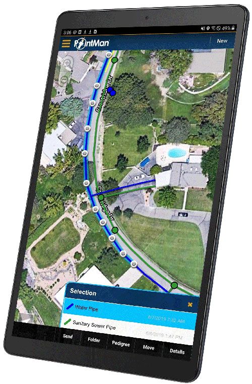
Precision-mapping company ProStar Holdings Inc. has integrated its PointMan software into the Vivax Metrotech vLoc3 with a GNSS real-time kinematic (RTK) receiver to create a utility-locate device.
Using the RTK-Pro internal cellular module with 4G LTE capabilities, the operator can connect to the NTRIP RTK caster that provides RTCM 3 corrections.
With the integration of PointMan with the vLoc3 RTK-Pro, critical buried infrastructure can be captured, recorded and displayed at survey-grade without additional external equipment or post-processing. The integration provides centimeter accuracy of the precise location of buried utilities in real time.
Data collected includes the type of utility, the depth of cover and the utility’s precise location.
Javad GNSS announces that, after a short retirement, Tom Hunter has rejoined the company as chief sales officer. Hunter will draw on more than three decades of GNSS industry experience, most recently with Javad GNSS and previously with Ashtech/Magellan as vice president.
“Tom is key to our operations,” said Nedda Ashjaee, CEO. “I am looking forward to reigniting this group of companies and continuing our four-decade tradition of bold innovation. Who better to do this with than the person who helped my father build the original company in the first place?”
Hunter will oversee sales channel development in support of a new market-driven roadmap developed by the executive team at Javad GNSS, also known as J-CORE.
Hunter’s association with Javad began in 1987 as one of the original seven people at Ashtech, Ashjaee’s namesake firm created shortly after his departure from Trimble Navigation. The firm brought numerous surveying industry firsts and other legendary products to market.
Company founder Javad Ashjaee passed unexpectedly in May 2020, leaving behind 200 loyal employees in offices around the globe. A strategic thinker, Ashjaee was known for operating “several steps ahead,” said one employee, having groomed his executive office and other support staff for a swift takeover in the event he were unavailable. Javad’s daughter Nedda, familiar to all who had conducted business with the firm, has spent the last 12 months carefully restructuring the business plan.
On March 31, Nedda Ashjaee, Tom Hunter and the rest of the J-CORE team hosted a two-day virtual gathering of global Javad GNSS dealers, technicians and other personnel, taking time to unveil the firm’s new strategic vision. The information and overall strategy was met with an overwhelmingly positive response.
Javad GNSS retains significant patent holdings relating to survey and mapping and offers what many of its customers believe to be one-of-a-kind system(s).
Hunter explained, “If you’re a surveyor or other positioning professional working with GNSS, you owe a debt of gratitude to Javad — the man dedicated his life to developing GNSS for the high-precision marketplace. You can see his hand in nearly every major GNSS survey system on the market today.”
“As we continue to develop and introduce new products in support of the surveying and reference station markets, we will use our exceptional technology and our U.S.-based world-class manufacturing facility to focus on new OEM applications and opportunities including strategic partnerships and private labeling,” Hunter said.
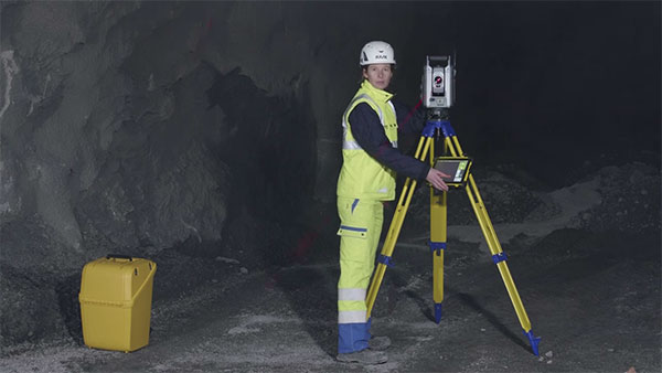
Trimble and Amberg Technologies are collaborating to provide a tunnel survey solution. The combined hardware and software solution will enable construction, mining professionals and surveying service providers in underground environments to make use of a complete field-to-office workflow.
The Trimble and Amberg solution enables tunnel surveyors to perform a variety of underground tasks such as excavation guidance, control, automated survey and stakeout of different tunnel elements using design information. In addition, it delivers a comprehensive module for digitalization of tunnel construction and further optimization of related processes.
The tunneling solution combines the robustness and the speed of the Trimble S series robotic total stations with the user-friendly workflows of Amberg Navigator field software running on a ruggedized Trimble TSC7 data collector or T100 tablet. The streamlined workflows are optimized for non-geospatial professionals, helping to keep tunneling and underground projects on time.
In the office, the designs from the Amberg Tunnel office software can be transferred to Amberg Navigator, either directly or using the cloud. Following the data collection and stakeout operations, the information is sent back to the office for detailed analysis, where inspection maps and reports can be produced as final deliverables inside Amberg Tunnel office software. This streamlined process can bring significant time and resource savings due to a more efficient workflow and easy-to-use interface.
The solution provides a full-featured workflow for tunnel construction surveys including:
project definition and design data preparation
graphical interface supporting instruments setup and georeferencing
automated data collection and real-time results
accurate stakeout of various tunnel elements (drill and blast holes, rock bolts)
efficient and comprehensive as-built analysis, reporting and archiving.
“Partnering with Amberg Technologies will provide our customers with an industry-leading tunneling solution to increase productivity when working in underground tunneling and mining environments,” said Ron Bisio, senior vice president of Trimble Geospatial. ”The domain-rich and easy-to-use Amberg solution in combination with our Trimble S series can increase confidence in the field and streamline deliverable creation.”
“Together with Trimble high-end surveying sensors, we can enrich our comprehensive tunnel solution with a more versatile offering and even better, address specific needs in ever more demanding construction environments,” said Svein G. Vatslid, CEO, Amberg Technologies AG.
The solution is expected to be available through Trimble’s Geospatial distribution channel in North, Central and South America this month.
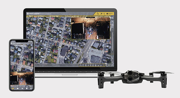
Parrot drones professional users benefit from an advanced control during complex fleet operations
Drone company Parrot is partnering with High Lander, which provides drone fleets with autonomous flight, intelligent airspace control, and coordinated air continuity through its Mission Control platform.
Combining Parrot ANAFI USA and ANAFI platform drones with High Lander’s Mission Control software, professionals can now access drone features through an easy-to-use dashboard.
“Parrot is continuously striving to provide our professional users with extended capabilities — allowing them to rapidly adapt their drone operations to fit their changing and urgent needs,” said Jerome Bouvard, Parrot director of strategic partnerships. “Drone automation and intelligence are at the heart of our product and software developments. This new partnership with High Lander represents another step towards enhanced automation and control capability of our drones.”
Using real-time device reporting and telemetry, first responders can autonomously manage their drone fleets while performing takeoff and landing, route-planning, and other crucial tasks — all from the intuitive comfort of the Mission Control Operations Center dashboard. The software’s seamless interface paired with the ANAFI USA’s ease-of-operation and rapid deployment provide more safety for responders and allow faster intervention during critical moments. Mission Control’s customized live link generation can also provide team-members onsite with an instant view of a drone’s video feed for fast assistance during search-and-rescue missions.
For surveying and mapping missions, operators can use improved control modes including Path (which sets an automated plan including multiple waypoints, telemetric, gimbal and payload settings) and Modeling & Mapping (which allows operators to survey an area in detail) as they efficiently create 2D maps and 3D models using Parrot ANAFI’s precise GPS coordinates capabilities.
Operators can also benefit from Mission Control’s Payload Sidebar, which enables switching instantly to thermal imaging, an invaluable tool for missions in search and rescue, police pursuits, or solar panel inspections. Parrot ANAFI USA’s integrated FLIR Boson Thermal sensor and 32x zoom make it easy to identify thermal anomalies and centimetric hot spots from an altitude of up to 40 meters.
“As a hardware-free system, Mission Control is compatible with leading drone manufacturers’ solutions, now including Parrot, to provide our customers with the freedom of customizing their drone fleets with best-in-class UAVs,” said High Lander CTO Ido Yahalomi.
High Lander is working with a number of prominent organizations including police departments, sheriff’s offices, fire stations, and forestry services, and has 12 active clients who will now be able to use Parrot’s ANAFI USA and ANAFI drones in their fleets.
The High Lander Pilot app is available for download on Android and iOS systems for use with ANAFI and ANAFI USA platform drones.
For more information about ANAFI USA, contact Parrot through the ANAFI USA contact form.
Inertial Labs has released a new generation of GPS-aided inertial navigation systems (INS) for applications such as UAVs, helicopters and lidar surveys.
The company also has released two new inertial measurement units (IMUs) for measuring angular rates and accelerations for motionless and dynamic applications.
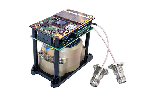
INS-DH-OEM
The INS-DH-OEM. (Photo: Inertial Labs)
The high-accuracy INS-DH-OEM is designed for easy integration into custom enclosures and higher order integrated system applications. It combines the HoneywellHG4930 inertial measurement unit (IMU) into a GPS-aided INS to provide high-accuracy orientation, position, velocity and timing for land and aerial systems.
Consisting of three axes each of high-precision accelerometers and gyroscopes, the accuracy of the HG4930 plays a key role in the exceptional performance of the INS-DH-OEM. With input from the IMU, the INS-DH-OEM has a pitch-and-roll accuracy of 0.015 degrees real-mean-squared (RMS) for dynamic applications, and a pitch-and-roll accuracy of 0.01 degrees for motionless applications.
Another key factor for the INS-DH-OEM is its use of the NovAtelOEM7720 dual-antenna GNSS receiver. The OEM7720 is an all-constellation, multi-frequency heading and positioning solution with TerraStar PPP correction services and advanced interference mitigation features.
With aiding data from the OEM7720, the INS-DH-OEM features a 2-meter baseline heading accuracy of 0.05 degrees RMS for both static and dynamic applications. As a result, the INS-DH-OEM is a high-performance solution in line-of-sight and beyond line-of-sight antenna-pointing applications.
A reliable solution in varying environments, the OEM7720 ensures that the INS-DH-OEM is outputting the most accurate GNSS-aided data by supporting GPS, GLONASS, BeiDou, Galileo, NavIC (IRNSS), and QZSS constellations.
The INS-DH-OEM can be applied in a wide range of aerial applications such as remote sensing, flight control and photogrammetry in which the INS-DH-OEM provides accurate positioning, navigation and timing (PNT) data for multi-rotor drones, fixed-wing drones and other UAVs performing these tasks. This data is paramount in the accuracy of these applications’ deliverables such as point clouds, orthomosaics and photogrammetric plots.
Weighing 280 grams and measuring 85.7 x 62.5 x 52.0 mm, the INS-DH-OEM is a lightweight, compact system that can be fitted with custom enclosures or integrated into higher order systems such as lidar payloads. It is compatible with scanners from many lidar manufacturers: Livox, Velodyne, Ouster and Quanergy. This adaptability, coupled with top-of-the-line subcomponents and Inertial Labs’ sensor-fusion expertise, make the INS-DH-OEM the suitable for UAVs, UGVs, antenna pointing, and many more applications.
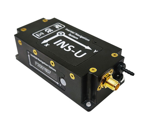
INS-U
The INS-U. (Photo: Inertial Labs)
The new INS-U GPS-aided INS with air data computer (ADC) output signal is based on a u-blox module.
The INS-U a fully integrated INS, attitude and heading reference system (AHRS), IMU and air data computer high-performance strapdown system that determines position, navigation and timing information for any device on which it is mounted.
The INS-U utilizes a single antenna, multi-constellation U-Blox GNSS receiver. With access to GPS, GLONASS, Galileo, QZSS, and BeiDou, the INS-U can be used in a variety of GPS-enabled environments and is protected against spoofing and jamming. Additionally, the INS-U is comprised of two barometers, a miniature gyro-compensated fluxgate compass, and tri-axis temperature calibrated advanced MEMS accelerometers and gyroscopes. These high-performance sensors, along with Inertial Labs’ new on-board sensor fusion filter, state of the art guidance and navigation algorithms, provide accurate position, velocity, and orientation of the device under measure.
Perhaps the most defining feature of the INS-U is its embedded ADC. An essential avionics component for modern UAV applications, an ADC outputs static & dynamic pressure, pressure altitude, calibrated & true airspeed, true angle of attack, rate of climb, and wind speed of the device under measure. This data, combined with inertial reference information, provides UAVs with accurate information about the unit and its relation to its environment.
By using data from an INS, AHRS, IMU and ADC, the INS-U provides a complete navigation solution for UAV and Helicopter applications. The unit can use time-of-flight aiding data from a ground station for long term GNSS-denied conditions as well as external position and heading so it can still output accurate PNT information regardless of the environment.
The INS-U is a lightweight and compact solution with dimensions of 82 x 40 x 26 mm and a weight of less than 200 grams. This, along with an IP67 environmental enclosure, ensures that the INS-U can meet the environmental requirements and size and weight restrictions of a wide range of applications.
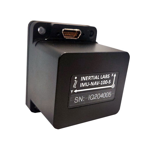
IMU-NAV-100
The IMU-NAV-100. (Photo: Inertial Labs)
The IMU-NAV-100 is a tactical grade IMU for wide range of higher order integrated system applications.
The newest addition to the Inertial Labs Advanced MEMS sensor-based family, the IMU-NAV-100, is now the best performing IMU that Inertial Labs offers. The IMU-NAV-100 is a fully integrated inertial solution that measures linear accelerations, angular rates, and pitch and roll with high accuracy utilizing three-axis high-grade MEMS accelerometers and three-axis tactical grade MEMS gyroscopes.
The IMU-NAV-100 features continuous built-in test, configurable communications protocols, electromagnetic interference protection, and flexible input power requirements which allow it to be easily integrated in a variety of higher order systems.
The IMU-NAV-100 line contains two options to accommodate a variety of projects.
The IMU-NAV-100-S is best for projects that require high performance stabilization for antenna and line-of-sight stabilization systems, motion control sensors, and platform orientation and stabilization systems. With a gyroscope angular random walk of 0.04 deg/√hr, the IMU-NAV-100-S is specialized to provide accurate data for stabilization applications.
The IMU-NAV-100-A is best used in a variety of systems such as GPS-aided INS, AHRS, and motion reference units. Regardless of the application, the IMU-NAV-100 is the company’s best performing IMU to date, providing a pitch-and-roll accuracy of 0.03 deg RMS. Fully calibrated, temperature compensated, and mathematically aligned to an orthogonal coordinate system, the IMU contains up to 0.5 deg/hr bias in-run stability gyroscopes and 0.003 mg bias in-run stability accelerometers with very low noise and high reliability.
The National Geodetic Survey (NGS) has revised an important technical document on the modernized National Spatial Reference System (NSRS). Zilkoski explores a use case on flood mapping, discussing an Elevation Certificate example, Flood Insurance Rate Map and Flood Insurance Study. NGS has scheduled a webinar for April 8 to discuss the four use case examples.
In February 2021, the National Geodetic Survey (NGS) revised NOAA Technical Report NOS NGS 67 Blueprint for the Modernized NSRS, Part 3: Working in the Modernized NSRS. Users can download the publication. See the box titled “NOAA Technical Report NOS NGS 67.”
This column will highlight one of the four use cases: “Use Case 1: Flood Mapping.” The case study discusses the Elevation Certificate (CE) example, Flood Insurance Rate Map (FIRM), and Flood Insurance Study (FIS).
The following is the scenario that NGS considered in this use case:
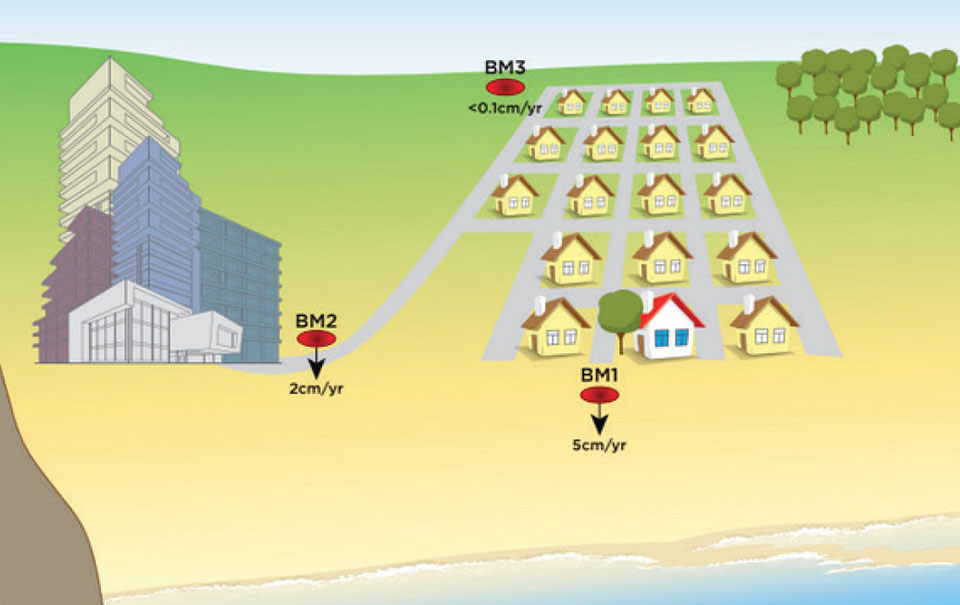
“This use case’s examples are set in an imaginary flood-prone coastal community experiencing non-uniform ground subsidence at the watershed scale (see Figure 10). Although many areas are not subject to this level of vertical motion, the full benefits of NSRS modernization are most apparent in this context. We illustrate differences in the use of the NSRS of today and the modernized NSRS with two common NFIP workflows. First, we consider steps anticipated in the certification of NAPGD2022 elevations for a NFIP Elevation Certificate. Second, we step into the shoes of a FEMA Mapping Partner to examine the ways future NSRS tools support more accurate mapping in Flood Insurance Rate Map (FIRM) and Flood Information Study (FIS) updates.”
I think this is a good scenario to use to demonstrate the full benefits of the NSRS modernization in areas of subsidence, but I believe there are important issues that will need to be addressed before the implementation of NAPGD2022 in flood mapping projects. I will highlight some of these issues later in the newsletter. First, let’s look at NGS example.
As depicted in figure 10 in NOS NGS 67 technical document, the area has three difference subsidence rates (<0.1 cm/yr., 2 cm/yr., and 5 cm/yr.). See the box titled “Diagram of fictional case study location for Use Case 1.” As NGS stated in the document, “Although many areas are not subject to this level of vertical motion, the full benefits of NSRS modernization are most apparent in this context.”
This may not be the typical situation of a flood mapping project but it should be noted that this type of high individual rates and large relative rate differences has occurred in the Houston-Galveston, Texas, region (see the following publications):
NGS’s example illustrates differences in the use of the NSRS today and the future NSRS with two common National Flood Insurance Program (NFIP) workflows. The example addresses surveyors performing a FEMA Elevation Certification using NAPGD2022 elevations, and the ways future NSRS tools support more accurate mapping in Flood Insurance Rate Map (FIRM) and Flood Information Study (FIS) updates.
It should be noted that according to the September 27, 2017, Office of Inspector General Department of Homeland Security OIG-17-110 report, FEMA’s goal is to review flood maps every five years.
“According to the National Flood Insurance Reform Act of 1994, FEMA must assess the need to revise and update all floodplain areas and flood risk zones identified once during each 5-year period. Thus, valid miles will expire every five years if not assessed. Failure to assess an NVUE compliant mile within the 5-year window will result in the mile being re-categorized as “Unknown” in the Needs Database. Unknown miles have not been subjected to the validation process to determine whether they reflect the current flood risk or are in need of restudy. In 2009, FEMA set a goal to attain 80 percent NVUE by the end of fiscal year 2014.” — Excerpt from Department of Homeland Security OIG-17-110 report
The modernized NSRS will help facilitate meeting this goal. This is described in NGS’s use case example:
NFIP products will primarily utilize the official NSRS reference epochs
“As the NFIP is structured today, NFIP products will primarily utilize the official NSRS reference epochs. Additionally, some NFIP products such as the EC form itself, as well as guidance, and technical references for FIRM and FIS preparation would benefit from updates that reflect changes to the NSRS. While the time-dependency and incorporation of a gravimetric geoid model will manifest as improved risk assessment reliability in inundation map products, we notably anticipate that NSRS modernization will have a limited impact on the basic structure of most recommended workflows associated with the NFIP of today. The most significant development is therefore the opportunity for FEMA’s National Flood Mapping Program (NFMP) to increasingly leverage the new capabilities of the NSRS to ensure that current, accurate ground elevation data is used, and to better incorporate relevant flood control structure and future conditions mapping data to support decision-making beyond the NFIP. Details of how the modernized NSRS can help FEMA achieve broader NFMP objectives and opportunities for data-driven case studies to explore this are described at the end of the use case.”
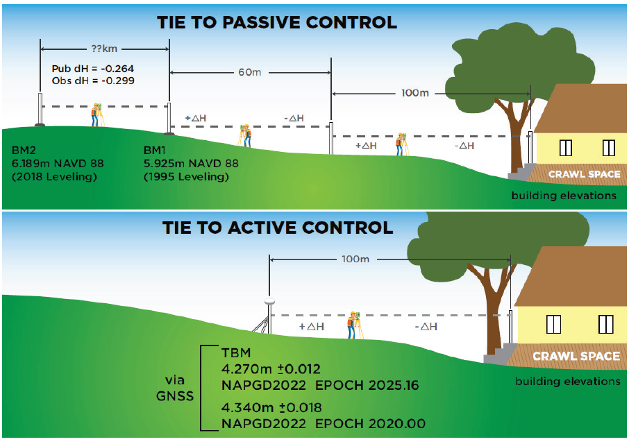
So, what does this really mean? The document uses two diagrams to explain how the new NSRS would be used to estimate a height for a FEMA Elevation Certificate (see box titled “Figure 11 from Use Case 1”). The top cartoon labeled “Tie to Passive Control” describes the process being performed today. That is, a surveyor locates the two closest marks that have published orthometric heights, follows the appropriate surveying procedures to ensure that the marks have not moved since the last time they were leveled to, and then performs the appropriate procedures to obtain the height for the Elevation Certificate. Depending on the location of the published orthometric heights in the area of the structure, this process could be very expensive. The lower cartoon labeled “Tie to Active Control” describes the process that will be used in the modernized NSRS using NADGP2022 heights. The user would occupy a temporary mark near the structure with GNSS to obtain a NAPGD2022 orthometric height computed using the appropriate ellipsoid height and geoid height value, and then perform the appropriate leveling procedures to obtain the height for the Elevation Certificate. This process will provide the most up-to-date height in the area.
Figure 11 from Use Case 1. Cartoon of Elevation Certificate field surveys based on establishing a tie to the NSRS via passive control leveling (top panel) and via active control with GNSS (lower panel). (Image: NGS)
There is an issue that should be noted here: the temporary mark determined using active control may provide the most up-to-date height at a particular location but that height may not be consistent with the heights used to establish the Base Flood Elevation (BFE). At first, someone would say, that’s good because it’s indicating that the flood hydraulics have changed on the floodplain map. However, without performing a detailed height analysis in the region, the user won’t really know whether the BFE value should be updated based on the current changes in topography in the floodplain region. In other words, if the entire region has subsidence at the same rate then the relative height difference hasn’t changed, and the new starting height may not be consistent with the published BFE on the FEMA Floodplain Map. In most floodplain mapping regions, the changes in heights are probably less than the accuracy of the maps but using the height of a mark that is not consistent with the BFE could place a homeowner’s house incorrectly in a flood zone. A good surveying practice would include occupying several marks with GNSS (or leveling between marks) that were involved in the creation of the flood insurance study and the generation of the floodplain map to ensure that the height used on the Elevation Certificate is consistent with the BFE. This is a good procedure to use for the current NSRS as well as the modernized NSRS. However, this is not economically practical using the current NSRS but could be in the new NSRS which is a major benefit of the modernized NSRS.
So, let’s look at the Houston-Galveston region using the latest information available.
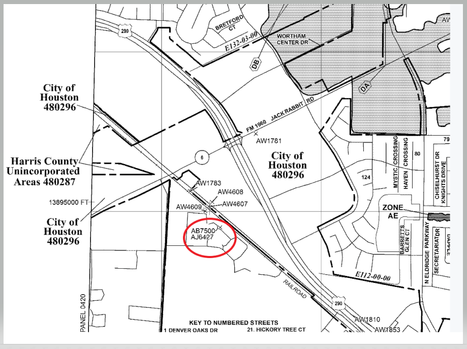
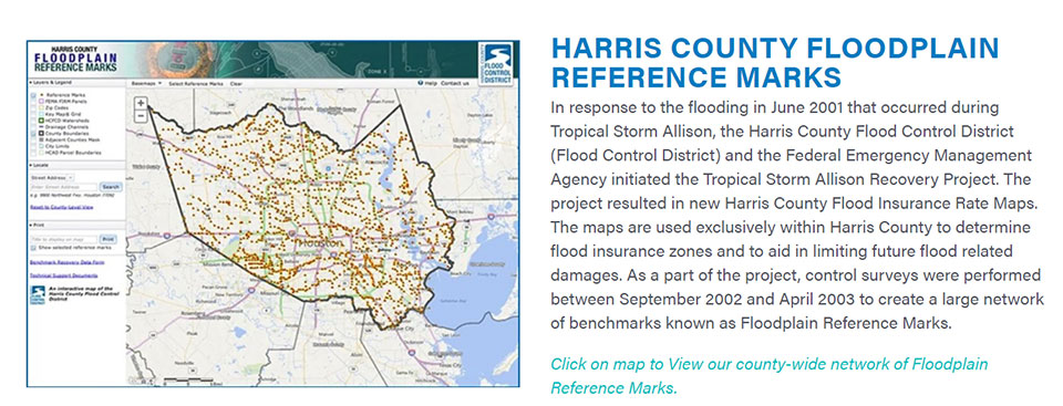
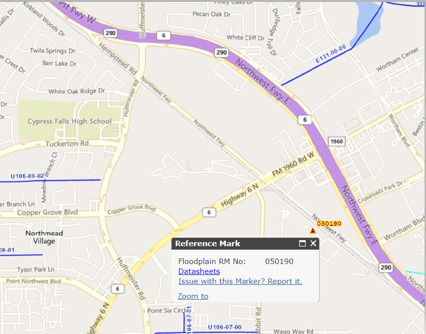
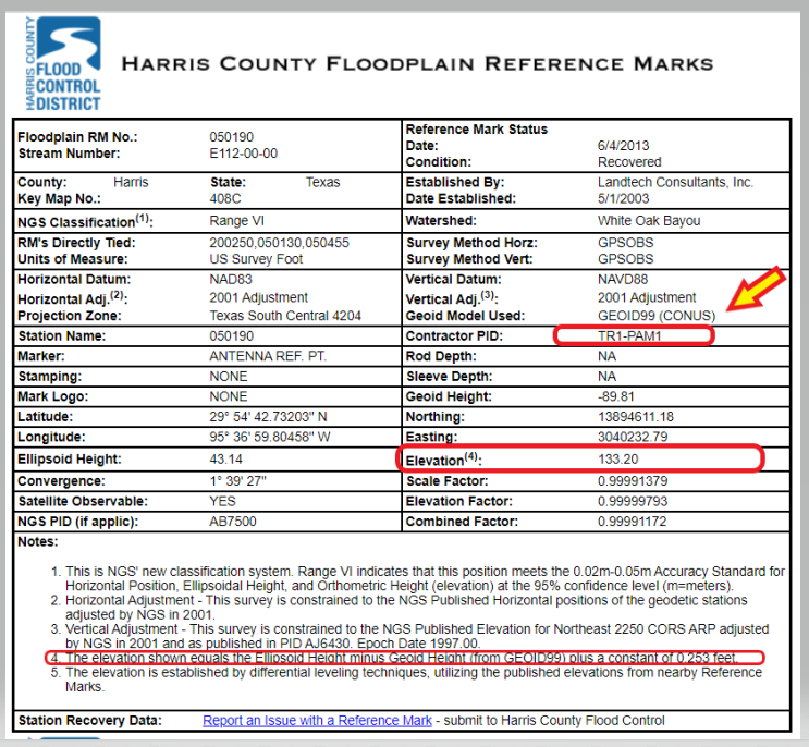
The box titled “Snapshot of Vertical Control from Harris County Floodplain Reference Marks Website” depicts the location of one of the reference marks, denoted as 050190.
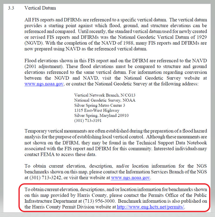
Clicking on the datasheets link, provides the information about the floodplain reference mark in the Harris County Flood Control District’s system (see the box titled “Harris County Floodplain Reference Mark Datasheet”).
It should be noted that the GNSS-derived orthometric heights were based on GEOID99 and the official hybrid geoid model published by NGS today is GEOID18. A GNSS-derived orthometric height computed using NGS’ webtool OPUS will use GEOID18 not GEOID99. The difference between GEOID99 and GEOID18 at this location is approximately 0.45 feet (0.138 meters). Users must ensure that they are using heights that are consistent with the BFE on the FIRM. The new NAPGD2022 will help to reduce issues associated with effects due to changes in geoid models.
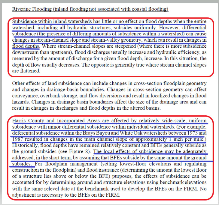
Page 113 from the November 15, 2019 Flood Insurance Study 48201CV001G addresses the issues associated with riverine flood in the region. (See the box titled “Page 113 from November 15, 2019 Flood Insurance Study 48201CV001G.”) The highlighted sections basically state that subsidence within inland watersheds has little or no effect on flood depths when the entire watershed subsides at the same rate. However, it also states that differential subsidence can cause changes in flood depths. The report goes on to say that the “Harris County and Incorporated Areas are affected by wide-scale, uniform subsidence with minor differential subsidence within individual watersheds.” It also states that “The local effects of subsidence may be adequately addressed, in the short term, by assuming that BFEs subside by the same amount the ground subsides.” The Houston-Galveston, Texas, region is a very complicated area due to the differential subsidence and numerous individual watersheds.
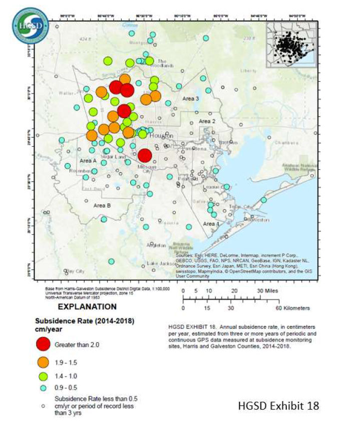
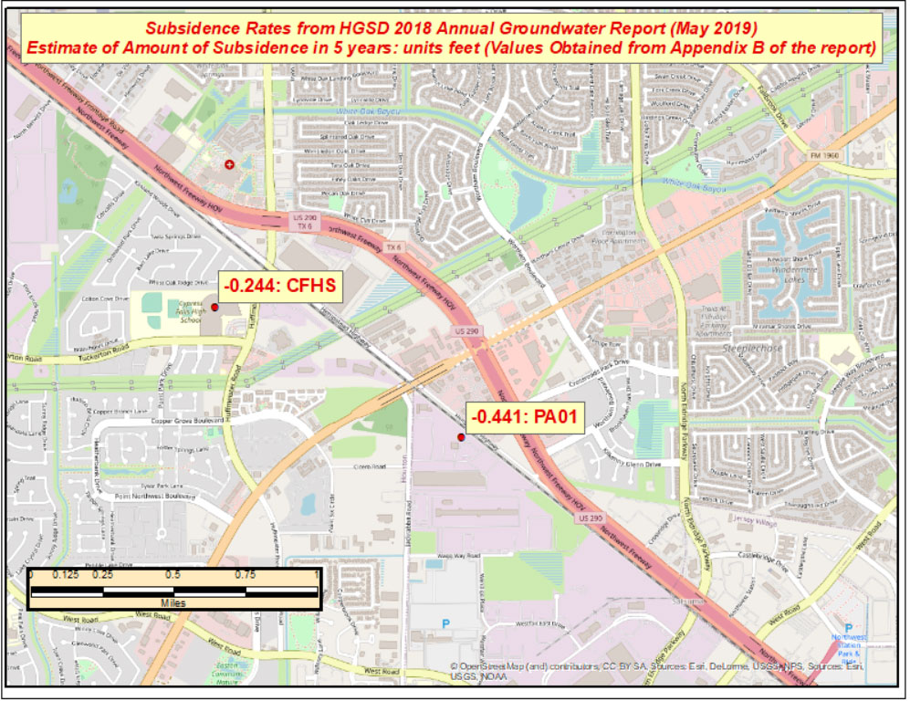
That said, let’s look some of the latest subsidence data in the region. The Harris-Galveston Subsidence District’s 2018 Annual Groundwater Report By Robert Thompson, William M. Chrismer, and Christina Petersen, PhD, P.E. provide some of the latest estimates of subsidence in the region. The box titled “HGSD Exhibit 18” depicts the locations of the GNSS sites used in the study. The plot provides the average compaction in centimeters over the past five years. The values range from 0.0 cm/year to greater than 2.5 cm/year.
HGSD Exhibit 18. This map shows the locations of the GPS sites throughout the area. The colored dots represent the average compaction over the past five years for each site, in centimeters. They range from 0.0 cm/year to greater than 2.5 cm/year. (Image: Harris-Galveston Subsidence District)
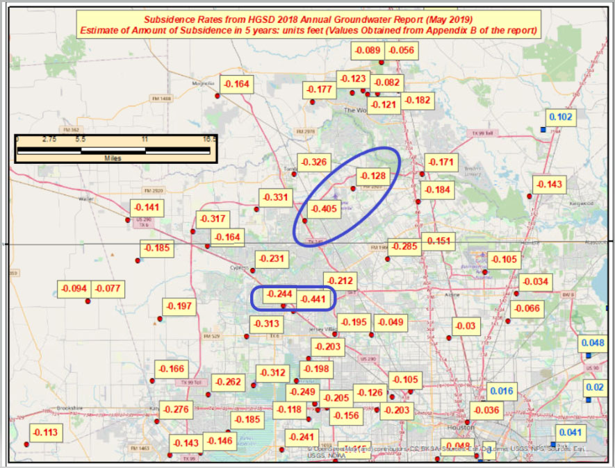
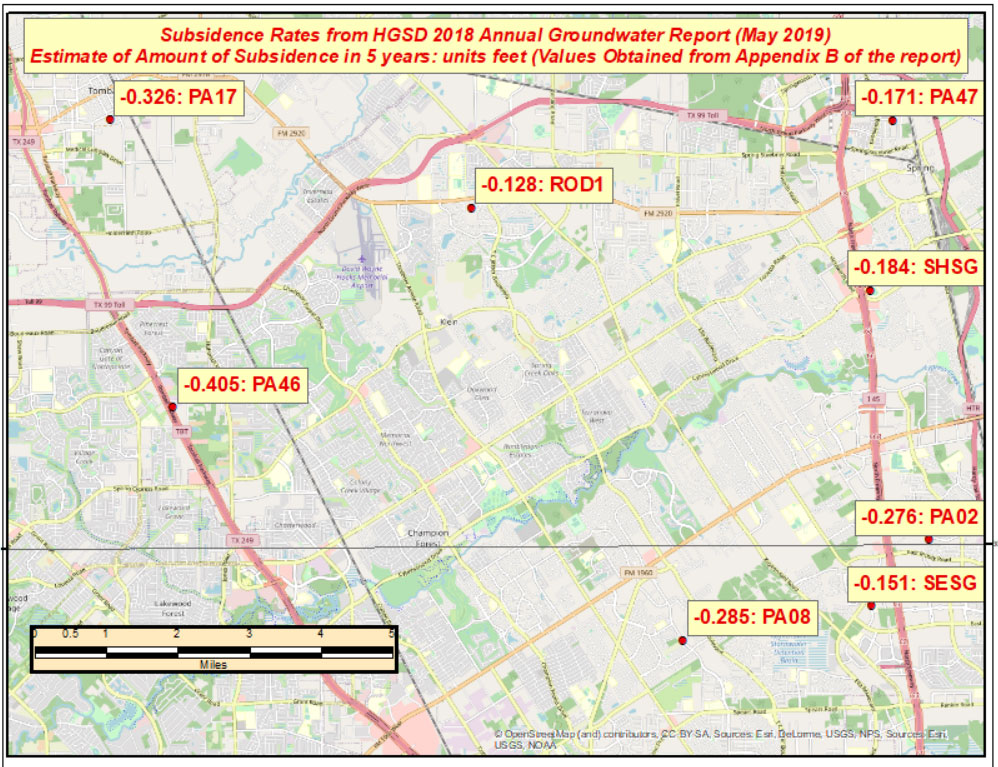
I used the information from Appendix B provided in the report to generate a few plots that show the estimate of subsidence in feet over 5 years. I’ve highlighted some marks that have large relative height changes. (Note: The units of the previous figure are centimeters; the units of the next several plots are feet.)
The relative height change between the two marks PA01 and CFHS, which are about 1.5 kilometers (approximately 1 mile) apart, is 0.197 feet in only 5 years. (See the box titled “Estimate of Amount of Subsidence in 5 Years at Pam 1– Units Feet.”)
The estimated relative height change between mark PA46 and ROD1, which are about 8 kilometers (approximately 5 miles) apart, is 0.277 feet in five years. (See the box titled “Estimate of Amount of Subsidence in 5 Years at Pam 46 – Units: Feet.”)
The effect of these large relative differences may not have any effect on the BFE on a particular watershed. These subsidence estimates are at a specific mark so they only provide information at a particular location. The new NAPGD2022 along with NGS’s webtools will enable users to economically obtain current, accurate heights in the entire region. Leveraging the capabilities of the new NSRS will help facilitate the implementation of FEMA’s goal of assessing the need to revise and update all floodplain areas and flood risk zones identified once during each five-year period.
This column highlighted the potential effects of subsidence on published heights in the Houston, Texas, region, which implies that most of the published heights based on older surveys in the region are not current or accurate.
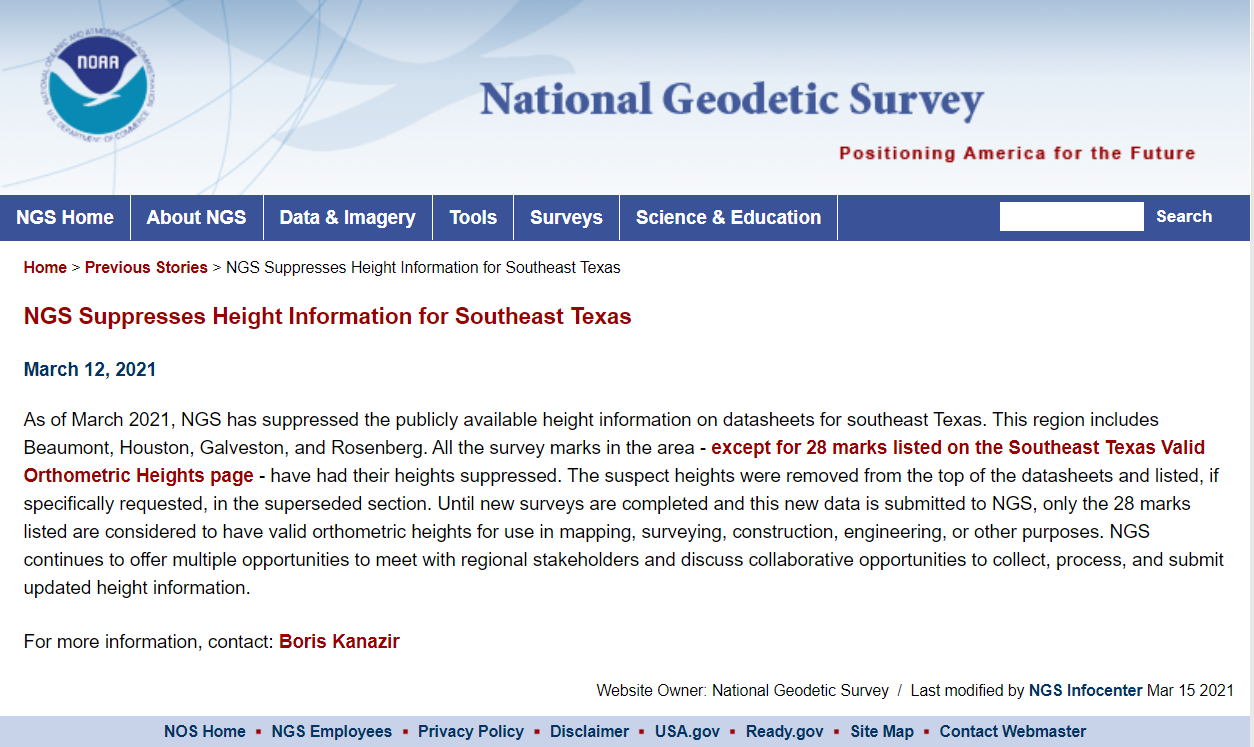
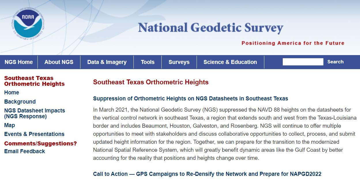
According to the announcement, only 28 marks will have publicly available orthometric heights on NGS datasheets in Southeast Texas. This NOAA website provides more information. See the box titled “NGS Southeast Texas Orthometric Heights.”
I would encourage everyone to check out the website to obtain a better understanding of what this suppression of published heights means to their operations. Future newsletters will address the suppression of the orthometric heights in Southeast Texas, and how users can help densify the network and prepare for the new, modernized NAPGD2022. Again, a benefit of the new modernized NSRS will facilitate the establishment of consistent, accurate NAPGD2022 GNSS-derived orthometric heights.
Lastly, NGS is convening the 2021 Geospatial Summit on May 4 and 5. The 2021 Geospatial Summit will provide updated information about the planned modernization of the National Spatial Reference System (NSRS). Register here.
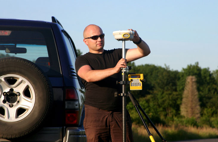
Unmanned aerial vehicles (UAVs) are something of a Swiss Army knife for the surveying and mapping communities. Commercial applications continue to grow, with UAVS — known as drones in the vernacular — gathering data and observations for agriculture, mining, utility inspections, natural resources, historical preservation, security, and many more applications.
UAVs perform high-risk tasks that keep workers out of harm’s way. They fly in places and situations difficult or impossible for aircraft to reach. They collect high-resolution imagery across the spectrum, accompanied by exact positioning and location data. They detect and help preserve the past in rich detail.
A study by Polaris Market Research predicts the UAV market will reach $15.62 billion By 2026, spurred not only by new use cases, but through miniaturization and improvement of components. Payload components that continue to improve include GNSS receivers, inertial measurement units, micro-electromechanical components, cameras of all types (RGB, thermal, hyperspectral and high-resolution video) and lidar. (For more on lidar with UAVs, see Diving into UAV lidar surveys.)
In these pages, we share a variety of case studies from companies taking part in the UAV revolution. In many of these use cases, companies saved considerable money using UAVs rather than more traditional surveying methods. In others, UAVs are helping to keep people safe.
In all cases, using UAVs provides a wealth of data that offer new insights, no matter the application.