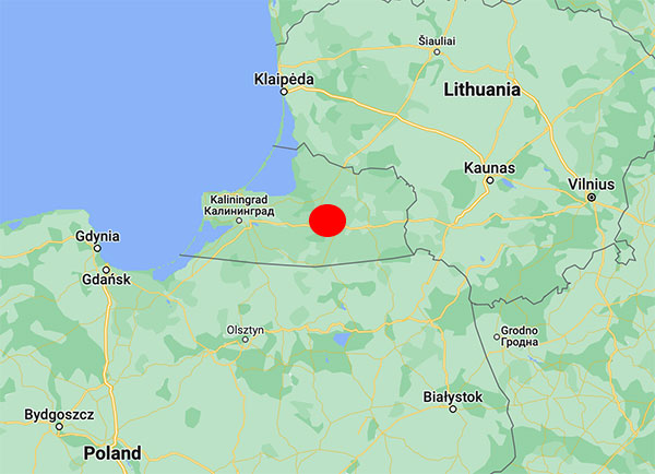
No cause for the abnormalities has been determined, but the vicinity to the Russian border during the Ukraine war seems to indicate intentional interference. In particular, interference occurs near the Russian province of Kaliningrad situated between Lithuania and Poland, both NATO members.
An aircraft operated by Lithuanian carrier Transaviabaltika has been unable to fly from Tallinn to Savonlinna for three days.
Traficom, the Finnish Transport and Communications Agency, has received numerous occurrence reports regarding GPS signal interference observed by aircraft. The interference began during the weekend and is still continuing.
On Tuesday, several aircraft reported GPS signal interference in the region around Mikkeli, Jyväskylä and Kuopio. An aircraft operated by Lithuanian carrier Transaviabaltika has been unable to fly from Tallinn to Savonlinna for three days.
Kaliningrad is the capital of the Russian province of the same name, sandwiched between Poland and Lithuania along the Baltic Coast. (Map: Google)
After receiving reports about GPS interference, Traficom on Monday requested Fintraffic Air Navigation Services Ltd (Fintraffic ANS) to issue a Notice to Airmen for pilots flying in the area.
“Flying is still safe. Airlines have procedures they follow if the GPS signal is lost,” said Director Jari Pöntinen. “Aircraft can use other systems to navigate and land safely. Air traffic control supports aircraft pilots with the help of other landing systems.” For final approach, traditional approach systems do not require a GPS signal.
Airlines make their own decisions on whether they can operate in an area where there is known to be interference to the GPS signal.
Traficom does not know what is causing the interference, but stated it will continue to monitor the situation and gather more information on the matter.
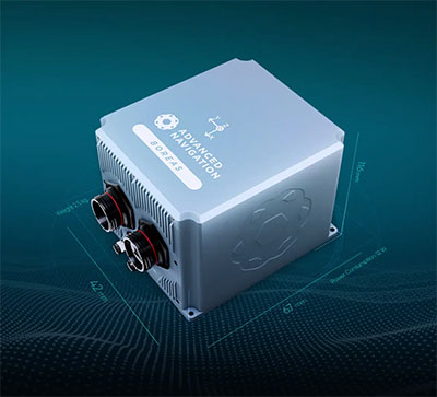
Advanced Navigation has launched a new fiber-optic gyroscope inertial navigation system (INS), named Boreas. It is an ultra-high accuracy, strategic-grade INS, offering a reduction in size, weight, power and cost. Boreas is the first product to be released based on Advanced Navigation’s new DFOG (digital fiber-optic gyroscope) technology, which is the culmination of 25 years of development involving two research institutions.
The Boreas is targeted at applications requiring always-available, ultra-high accuracy orientation and navigation including marine, surveying, subsea, aerospace, robotics and space.
“Boreas is the first product on the market to offer our patent-pending DFOG technology,” said Advanced Navigation CEO Xavier Orr. “DFOG represents a step-change for fiber-optic gyroscopes. With Boreas’ ultra-high-accuracy and strategic-grade performance combined with the reduction of size, weight, power and cost by 40%, we will be able to enable new industries and applications that were never possible before.”
The Boreas delivers strategic-grade bias stability of 0.001 deg/hr. This allows it to achieve ultra-high roll/pitch accuracy of 0.005 degrees and heading accuracy of 0.006 degrees. Boreas allows for full independence from GPS with dead-reckoning accuracy of 0.01% distance traveled with an odometer or Doppler velocity log.
The Boreas features ultra-fast gyro compassing, taking only 2 minutes to acquire heading in both stationary environments or on the move. Gyro compassing allows the system to determine a highly accurate heading of 0.01 degrees secant latitude without relying on magnetic heading or GPS.
The Boreas contains Advanced Navigation’s sensor-fusion algorithm, which is more intelligent than the typical extended Kalman filter. The algorithm is able to extract significantly more information from the data by making use of human-inspired artificial intelligence. It was designed for control applications, with a high level of health monitoring and instability prevention to ensure stable and reliable data.
Advanced Navigation designed Boreas from the ground up for reliability and availability. Both the hardware and software are designed and tested to safety standards, and it has been environmentally tested to mil standards.
The system is designed for a mean time between failures of 500,000 hours. Additional features include Ethernet, CAN and NMEA protocols, as well as a disciplined timing server providing PTP. An embedded web interface provides full access to all of the device’s internal functions and data. Internal storage allows for up to one year of data logging.
Ensures safe operations through reliable, robust and continuous positioning with GNSS+INS integration
Hexagon | Veripos has expanded its inertial solution SPAN GNSS+INS technology from NovAtel, also part of Hexagon, to dynamic positioning (DP) applications and vessels.
SPAN technology delivers a deeply coupled GNSS and inertial navigation system (INS) that provides robust, reliable and continuous centimeter-level positioning for operators to maintain safety and maximize uptime.
With a GNSS+INS solution, DP vessels can bridge outages in GNSS tracking and through short periods of radio-frequency interference, jamming or spoofing.
Veripos is a leader in offshore high-precision positioning, delivering reliable and trustworthy GNSS solutions such as the LD900 receiver, PPP correction services and positioning visualization software. This expertise is demonstrated through SPAN technology’s deep coupling of GNSS and inertial measurements.
Deep coupling describes how inertial measurements enhance the signal tracking for GNSS solutions, leading to improved resiliency against GNSS outages and enabling rapid reacquisition in case of interruptions. SPAN technology builds system robustness against potential signal outages, interference or disruptions while optimizing operational efficiency.
“The robust positioning, heading, velocity and attitude measurements generated from a deeply coupled GNSS and inertial solution like SPAN technology is a game-changer to dynamic positioning operations,” said David Russell, marine segment portfolio manager at Hexagon’s Autonomy & Positioning division. “SPAN technology has a proven track record of bridging outages, enabling rapid reacquisition of signals, and building a reliable and robust positioning system. It’s the best option for vessels to ensure an added layer of resiliency and achieve continuous centimeter-level accuracy across all conditions.”
SPAN GNSS+INS technology is compatible with commercial inertial measurement units (IMUs) and scalable with the LD900 GNSS receiver, Quantum visualization software and APEX correction services.
Partnership to bring integrated precision GNSS solutions to automotive and industrial customers
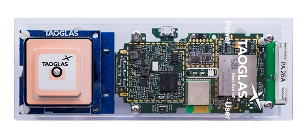
Swift Navigation, a San Francisco-based GNSS firm, and Taoglas, a provider of internet of things (IoT) solutions, have announced a strategic partnership to integrate their technologies to deliver pre-tested, low-risk, high-precision GNSS solutions to a broad customer base.
The Taoglas EDGE RTK Starter Kit has high-precision GNSS with U.S. 4G/3G cellular connectivity. (Photo: Taoglas)
The partnership will provide positioning solutions for automotive, micromobility, delivery, robotic and industrial customers. Specifically, the Taoglas EDGE Locate IoT platform and EDGE RTK Starter Kit now come pre-integrated with Swift’s Skylark precise positioning service.
Bringing pre-integrated, high-accuracy positioning products to these industries in an easy-to-implement solution will greatly improve the accuracy of the positioning data delivered, the companies state.
Together, Swift and Taoglas deliver high-precision GNSS solutions to customers around the globe by utilizing Taoglas’ IoT platforms and Swift’s Skylark seamless, cloud-based corrections — available in advanced SSR (state space representation) or industry-standard formats. The pre-integration allows customers to bypass module-level validation, integration and engineering efforts with an out-of-the-box solution.
“Swift Navigation is excited to begin this partnership with Taoglas and align our visions of making accurate positioning easily accessible across industries,” said Swift CEO Timothy Harris. “We look forward to offering our products as an integrated solution to make it easier for customers across the globe to benefit from affordable and accurate positioning.”
“We are delighted to be partnering with Swift Navigation to enable companies to overcome the challenges of delivering their high-precision positioning-based IoT solutions.,” said Ronan Quinlan, co-founder and joint CEO of Taoglas. “Our worldwide team of design, development, test and manufacturing engineers is dedicated to delivering IoT software and hardware solutions on time, the first time, for leading technology enterprises.”
Additional products will soon be available from Swift, Taoglas and their channel partners. Customers have the ability to pre-order now by contacting [email protected] or [email protected].
Canada is leveraging advanced surveillance capabilities to enhance safety and efficiency by implementing a new mandate that will require aircraft operators flying in certain domestic airspace to meet Automatic Dependent Surveillance – Broadcast (ADS-B) Out performance requirements.
ADS-B uses GNSS technology to calculate an airplane’s precise location, speed and direction. This information is transmitted twice per second, providing greater situational awareness for air traffic controllers. It also provides increased flexibility to accommodate airline and customer preferred routes.
The mandate will take effect in Class A and B Canadian airspace above 12,500 feet on Feb. 23, 2023.
“ADS-B is a foundational building block for our future airspace and operations,” said Raymond G. Bohn, president and CEO of Nav Canada. “The Canadian equipage mandate — when combined with Nav Canada’s space-based surveillance capabilities — will enhance safety and service.”
“The aviation sector plays an essential role in connecting Canadians to each other and the world,” said the Honourable Omar Alghabra, Minister of Transport. “We welcome advancements and innovation that enhance the safety and environmental sustainability of our transportation networks and supply chains.”
The equipage requirements of Canada’s ADS-B mandate are in line with a growing number of other countries in the world, and the adoption of satellite-based surveillance technology ensures long-term alignment with the global aviation system.
Space-based ADS-B is already being used and delivering safety and efficiency benefits to suitably equipped aircraft over Hudson Bay, the North Atlantic and in domestic airspace above 29,000 feet in Canada. In December 2021, Nav Canada began providing service to appropriately equipped aircraft below 29,000 feet in the Montreal Flight Information Region and plans to expand to the Edmonton and Winnipeg Flight Information Regions later this year, prior to the mandate going into effect in 2023.
Future implementation of a mandate in areas within Class C, D and E will leverage a phased approach to help achieve the maximum benefits of a performance-based mandate for Canadian airspace. Aircraft operators and owners will have adequate time to meet the equipage requirements to use space-based ADS-B technology across the country. Implementation in these classes of airspace, to occur no sooner than 2026, will be determined pending further assessment.
About the ADS-B mandate
To meet the ADS-B Out mandate, aircraft will be required to:
Be equipped with an appropriate transponder with ADS-B Out capabilities and performance with the applicable standard of Radio Technical Commission for Aeronautics (RTCA) DO-260B, “Minimum Operational Performance Standards” or newer.
Have antenna capability for broadcast toward space-based ADS-B receivers emitting 1090 MHz extended squitter. This requirement can be met either through antenna diversity (the use of a top and a bottom antenna) or with a single antenna capable of transmitting both toward the ground and up toward satellites.
The Navigation Sensor Switching in Hostile Environments (NAV-SSHE) project aims to design, prototype and demonstrate new solutions for positioning, navigation and timing using 5G plus GNSS for critical applications in hostile environments. NAV-SSHE is supported by the European Space Agency (ESA).
Geolocation company M3 Systems Belgium is taking part in the project in collaboration with Telespazio Belgium. The project began in September 2021 and will last until January 2023.
In the context of NAV-SSHE, M3 Systems Belgium will implement both a GNSS and a 5G signal based on positioning engines. The output of both engines will be fused to provide a unique solution with increased robustness.
The complete system will be demonstrated on two real-use cases:
autonomous vehicles on an airport platform (specifically autonomous lawn mowers)
autonomous docking of vessels in port
The demonstrations will also be used to test potential use of these technologies for drone applications — specifically for the navigation system of the autonomous remotely piloted aircraft Boreal.
Qualcomm Technologies Inc. and Ferrari N.V. have entered a strategic technology collaboration aimed at helping accelerate the digital transformation of Ferrari.
Qualcomm Technologies will serve as Ferrari’s systems solutions provider for its upcoming Ferrari road cars, as well as a Premium Partner for the Scuderia Ferrari Formula 1 team and Ferrari eSports team.
Ferrari will work with Qualcomm Technologies to utilize the Snapdragon Digital Chassis to bring the latest automotive technology advancements to Ferrari road cars.
The Snapdragon Digital Chassis is comprised of open and scalable cloud-connected platforms needed for next-generation vehicles, which includes telematics and connectivity, the digital cockpit, and advanced driver-assistance systems (ADAS) functions. It utilizes a unified architecture to deliver enhanced safety and immersive digital experiences updateable throughout the lifetime of the vehicles.
As a part of the agreement, Qualcomm Technologies and its partners will also work with Ferrari to design, develop and integrate Ferrari’s digital cockpits.
Qualcomm Technologies will begin serving as a Premium Partner of the Scuderia Ferrari Formula 1 team at the start of the 2022 FIA Formula One World Championship race season, where Snapdragon will be featured on the new Scuderia Ferrari’s F1-75 single-seaters. The Maranello marque’s eSports activities will also be part of the official partnership.
The Snapdragon Digital Chassis connects cars to the cloud. (Image: Qualcomm)
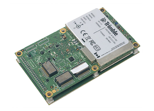
New hardware and software platform provides accuracy, position for land-vehicle system integrators
Photo: Applanix
Applanix, a Trimble Company, has announced the Trimble AP+ Land GNSS-inertial OEM platform for accurate and robust position and orientation for georeferencing sensors and positioning vehicles in land mobile-mapping applications.
The platform enables users to accurately and efficiently track and monitor fleets and produce high-definition (HD) maps and 3D models. It can also serve as a reference solution for advanced driver-assistance systems (ADAS) testing, even in challenging GNSS environments.
The comprehensive Trimble AP+ Land is small enough to integrate into compact mobile-mapping systems. It is compatible with virtually any type of mapping sensor, including single- or multi-lidar systems, video cameras, photogrammetric and panoramic cameras, and similar sensors.
Configurable to meet the mapping, positioning and direct georeferencing (DG) accuracy demands of mapping and positioning applications in challenging GNSS signal environments, the Trimble AP+ Land solution features:
Dual embedded survey-grade GNSS chipsets that can receive multi-frequency and multi-constellation signals
Dual custom-designed inertial measurement units (IMU)
Distance measurement indicator (DMI)
Compact size
Low power consumption
Optional RTK and Trimble CenterPoint RTX real-time correction service support
Full integration and post sales support through the Applanix Global support network
“We have taken the most advanced features of Applanix inertial and Trimble GNSS technology, and packaged them into a powerful compact and versatile solution optimized for mobile mapping and positioning applications,” said Joe Hutton, Applanix’s director of inertial technology, air and land products. “We remain committed to our customers’ success by developing flexible and scalable positioning solutions such as the AP+ Land and more.”
The Trimble AP+ Land OEM solution is supported by the Applanix POSPac MMS post-processing software, which features Trimble CenterPoint RTX post-processing for centimeter-level positioning globally without the need for base stations. These capabilities make it a suitable for integrators to produce a highly efficient land mobile-mapping system.
For lidar integrators, the Trimble AP+ Land OEM is compatible with the POSPac MMS LiDAR QC tools. SLAM technology computes the IMU to lidar boresight misalignment angles and also adjusts the trajectory to achieve the highest level of georeferencing accuracy in the generated point cloud.
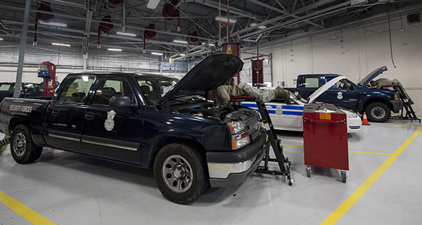
U.S. Air Force Airmen repair government-operated general-purpose vehicles at Moody Air Force Base, Georgia. (Photo: U.S. Air Force/Airman 1st Class Lauren M. Johnson)
The U.S. Air Force will equip its 21,000 general-purpose vehicles with Geotab fleet-management technology after the company was awarded a sole-source contract.
Geotab received FIPS 140-2 validation for its cryptographic library in February 2019 as well as FedRAMP authorization and ISO 27001 certification for its telematics platform. These compliance certifications and authorizations validate Geotab’s system and organizational processes, enabling the company to offer its fleet-management services to all levels of federal, state and local government agencies.
Geotab’s fleet-management technology for the Air Force is secure and customized. It includes the following features to help the service more effectively manage its vehicles:
automated odometer capturing
engine diagnostics
problem predictive analytics
fuel data
custom reporting
GHG reduction dashboards
fleet right-sizing reporting
Selected for its integration capacity and proven commitment to information security, the sole-source award from the Department of the Air Force yields an Authorization to Operate (ATO) within the Department of Defense (DoD). The authorization will allow other DoD agencies to leverage Geotab services by piggybacking off of this DAF ATO.
Geotab fleet-management products are used by more than 2,000 government agencies and departments at all levels to capture, measure and analyze crucial fleet data with deep granularity. “Winning this sole-source contract from the Department of the Air Force further solidifies Geotab’s ability to collaborate with agencies that operate at the highest levels of national data security and to provide a customized and highly secured telematics solution,” said Dan Zdarko, business development manager, federal government, Geotab.
“It is vitally important that the technology we deploy in our fleets meet the highest standards of data security put forth by the U.S. government,” said Tim Patterson, program management flight chief from the U.S. Air Force’s 441st Vehicle Support Chain Operations Squadron at Langley Air Force Base in Virginia. “Our objective is to enhance fleet-management strategies and reduce the total cost of ownership longer term across the Department of the Air Force.”
How inertial systems and GNSS availability will help
By Kana Nagai, Matthew Spenko, Ron Henderson and Boris Pervan
Self-driving cars in urban environments can be problematic. The required multi-sensor automated systems will include GNSS, but buildings block and reflect GNSS signals, reducing system availability and accuracy. Researchers from the Illinois Institute of Technology report on how inertial navigation systems coupled with wheel-speed sensors and vehicle dynamic constraints can help.
Innovation Insights with Richard Langley
ARE WE THERE YET? This was a familiar refrain from the backseats of parents’ cars when traveling to a holiday destination or to grandparents when I was growing up. We didn’t have videos on a display attached to the seats in front of us or (who could imagine?) our own personal communication device on which we could call up games, movies or social media channels.
But I’m not talking about that complaint from our childhoods. I’m asking if we have arrived at the era of the self-driving car. The answer is yes and no. It all depends on what you mean by “self-driving.” We reviewed some of the technologies needed for self-driving or autonomous vehicles in this column in June 2019. And we indicated in the introduction to that column that vehicle autonomy has several levels. SAE International, formerly known as the Society of Automotive Engineers, has defined six levels of autonomy that can be briefly described as Level 0 – no automation; Level 1 – hands on/shared control; Level 2 – hands off; Level 3 – eyes off; Level 4 – mind off; and Level 5 – steering wheel optional.
Already, Level 1 automation is widely available in modern cars with adaptive cruise control, parking assistance, lane-keeping assistance and automatic emergency braking among the features being offered.
Level 2 automation, where the automated system takes full control of the vehicle’s acceleration, braking and steering, is available in some production models, although the “hands-off” designation is not to be taken literally — most motor vehicle laws require drivers to keep their hands on the steering wheel.
Between Level 2 and Level 3, we have conditional automation — the car can drive itself, but the driver must stay alert and be prepared to take over immediately.
Level 3 is high automation, where a computer fully drives the car at certain times on certain routes such as a highway; while the driver can perform other tasks such as reading a book, they must be prepared to take over operation of the vehicle within a few seconds if alerted by the automated system. While test campaigns are still ongoing, some jurisdictions permit Level 3 operation by ordinary drivers on some roads, and customers will soon be able to buy vehicles with this level of automation. Widespread use of
Level 4 and Level 5 automation is further off (some would say quite a way off) and remains in development. But famously, last year, Toyota operated Level 4 self-driving shuttle vehicles around the Tokyo 2020 Olympic Village.
A lot more work needs to be done before we will have arrived at the era of the fully self-driving car that will be able to travel on any road, anywhere in the world, all year around, in all weather conditions. In particular, self-driving cars in urban environments (as opposed to highway driving) can be problematic.
The required multi-sensor automated systems will include GNSS, but buildings block and reflect GNSS signals, reducing system availability and accuracy. In “Innovation” this month, researchers from the Illinois Institute of Technology report on how inertial navigation systems coupled with wheel-speed sensors and vehicle dynamic constraints can help.
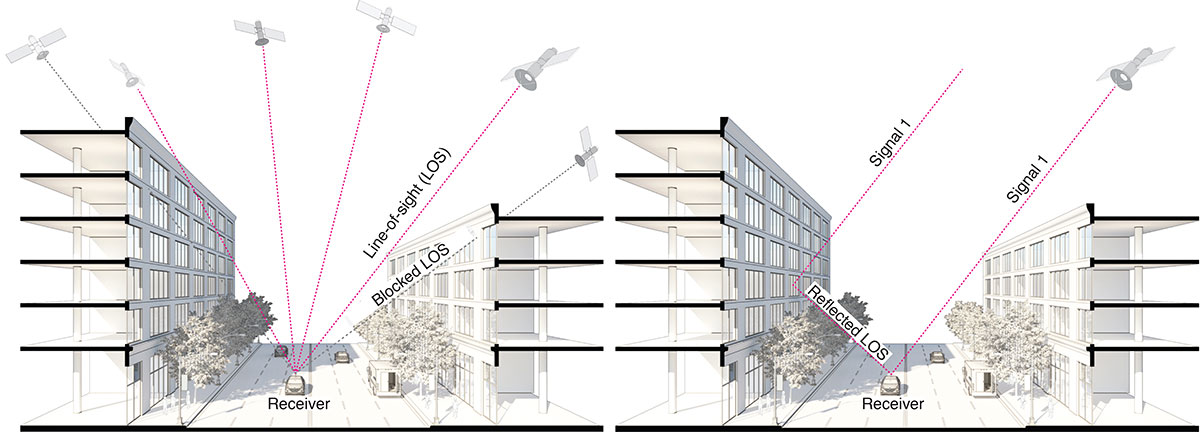
GNSS provides navigation services globally, but satellite visibility in urban areas is limited by high-rise buildings. This creates a mixture of GNSS available and denied environments (see FIGURE 1) — users do not generally know where the system can maintain sufficient levels of accuracy and integrity for a particular application. To begin to address the issue for self-driving cars, we evaluated GNSS-only availability in downtown Chicago.
FIGURE 1. The figure depicts three types of potential GNSS signal reception: direct LOS signals and blocked LOS signals (left) and reflected LOS signals (right). (Image: Authors)
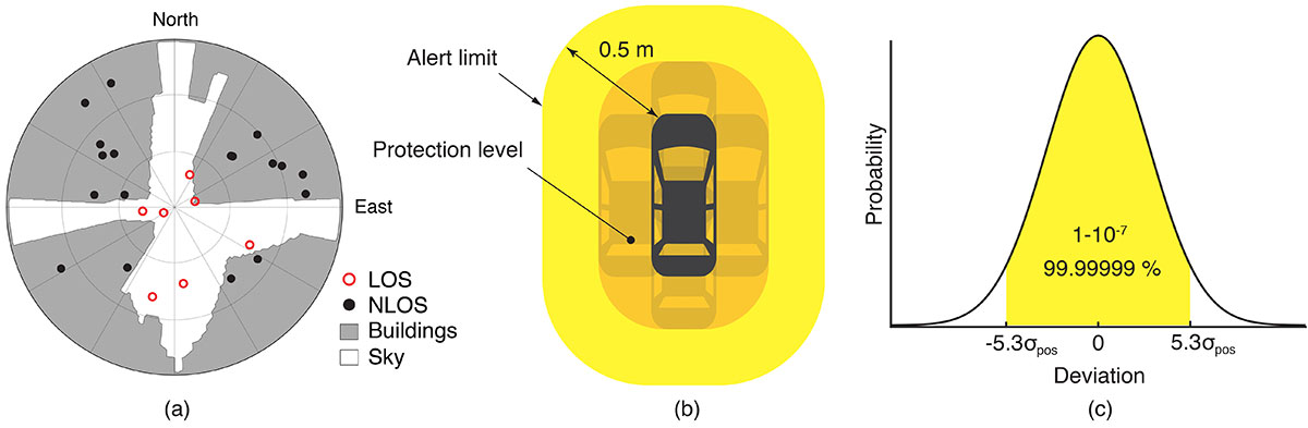
GNSS signal prediction in urban environments has been conducted in previous work. For example, the concept of “shadow matching” was developed to identify GNSS signal blockages in urban canyons. Overlaying sky plots on a hemispherical sky view can be used to distinguish between line-of-sight (LOS) and non-line-of-sight (NLOS) signals (see FIGURE 2a). Reflected rays can be predicted using Householder transformations to reveal potential multipath conditions. Satellites producing blocked or reflected (NLOS) signals should be excluded to maintain integrity.
FIGURE 2. (a) A hemispherical sky view in an urban environment. (b) Illustration of a protection level and an alert limit. To ensure integrity, the protection level must not exceed an alert limit. (c) The allowable probability of exceedance is assumed to be 10−7 in this work. (Image: Authors)
When the number of visible satellites is greater than three, GNSS can resolve vehicle position. However, even in cases where enough satellites are visible, the satellite geometries are generally weak because the dilution of precision (DOP) is adversely affected by the buildings partially blocking the sky. Horizontal positioning error must be bounded by a protection level computed by the vehicle. Then, for navigation to be deemed available, the protection level must not exceed a required alert limit (see FIGURE 2b). The maximum allowed probability of exceedance (see FIGURE 2c) and the alert limit can together be used to determine the maximum allowable position error standard deviation.
Even if the protection level is far below the alert limit in an open-sky environment, it will frequently exceed the alert limit once the vehicle enters a city. GNSS alone is generally not able to maintain availability, so integration with other sensors is needed. Tightly coupling inertial navigation systems (INS) with GNSS using the extended Kalman filter (EKF) provides better estimation in urban environments. The EKF algorithm also enables integration of wheel-speed sensors and vehicle dynamic constraints. These integrated navigation systems will improve availability, but it is still unclear how long such a system can be expected to maintain fault-free integrity in a congested city.
Focusing on the problem of self-driving cars in urban environments, we evaluate protection levels of navigation with practical integrated sensors: GNSS, INS, a wheel-speed sensor (WSS) and vehicle dynamic constraints (VDC). The goal is to develop the means by which we can determine locations where external ranging sources (such as lidar) are needed to maintain continuous navigation with fault-free integrity.
GNSS-ONLY AVAILABILITY
For GNSS availability evaluation, we assume an integrity requirement that the probability of exceeding a 0.5-meter alert limit must be lower than 10−7. The 0.5-meter alert limit therefore corresponds to approximately five times the position standard deviation, so the maximum allowable position error standard deviation is then approximately 0.1 meters. Accuracy at this level clearly requires differential GNSS carrier-phase measurements. We assume a nominal GNSS double difference (DD) carrier ranging error standard deviation of approximately 0.02 meters, and that carrier cycle ambiguities can be readily resolved in an open-sky environment prior to initiation of vehicle motion.
Given the assumptions made of the maximum allowable position error standard deviation and the GNSS ranging error standard deviation, the maximum allowable horizontal dilution of precision (HDOP) is about 5.
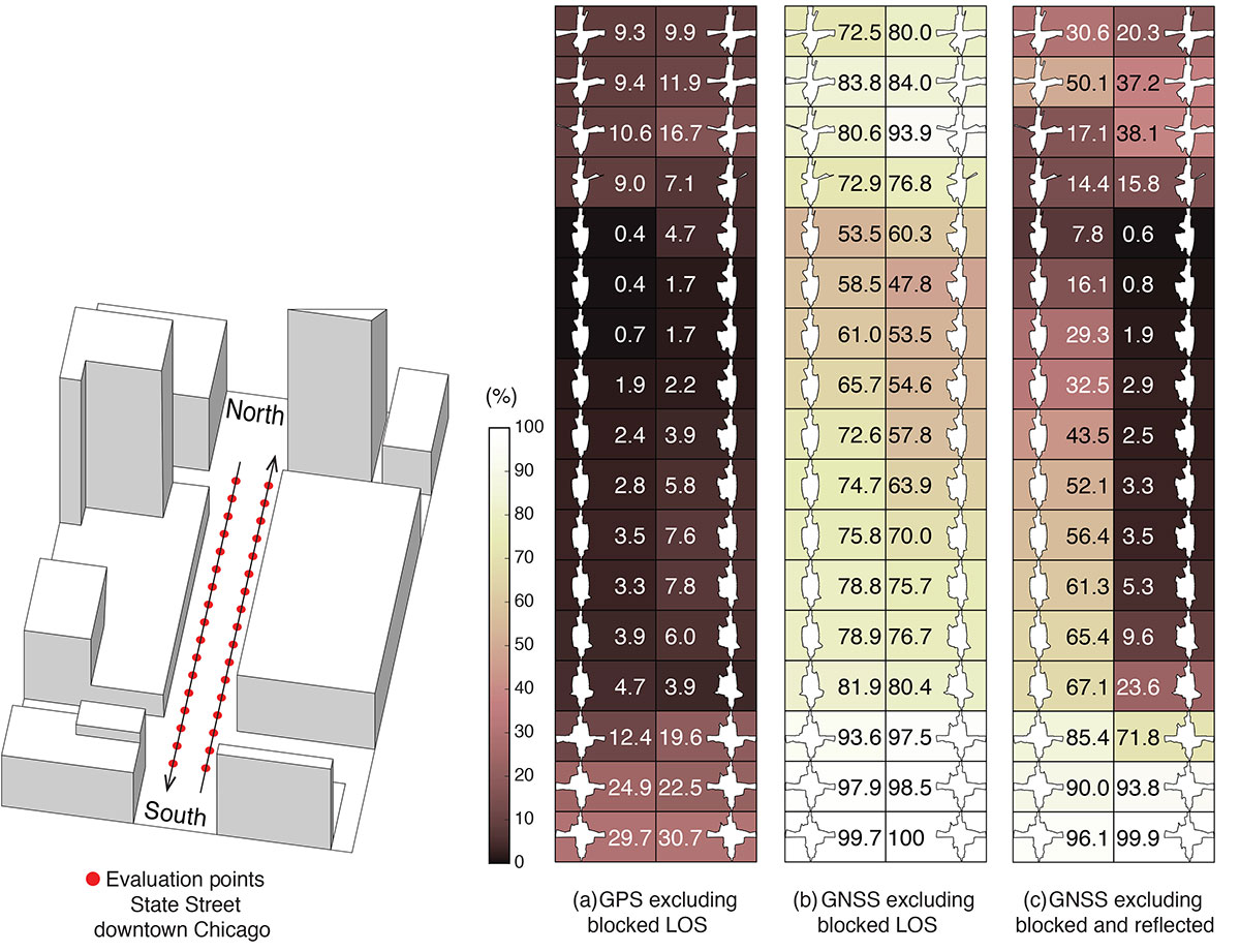
FIGURE 3 shows GPS and GNSS availability — the fraction of time the HDOP requirement is met over 24 hours — along a section of State Street in downtown Chicago. The availability results using GPS only and excluding only blocked LOS signals ranged from 0% to 9% along the block and 9% to 30% at the intersections (see FIGURE 3a). Using four full GNSS constellations (GPS, Galileo, GLONASS and BeiDou), availability ranged from 48% to 82% along the block and 72% to 100% at the intersections (see FIGURE 3b).
FIGURE 3. The percentage of GPS or GNSS availability in 3D-mapped downtown Chicago. We exclude satellites producing blocked LOS signals or both blocked and reflected LOS (NLOS) signals from the measurements. Each column expresses a lane of southbound or northbound travel. The availability is the percentage of total time when HDOP meets the self-driving car integrity requirements in 24 hours. (Image: Authors)
When we also excluded satellites producing reflected LOS signals that reach the vehicle, the availability dropped significantly at every point (see FIGURE 3c). We assert that FIGURE 3c expresses the reality of GNSS availability because building-reflected multipath signals degrade positioning accuracy and would affect integrity negatively. It’s obvious from these results that GNSS alone is insufficient to meet the autonomous driving requirements in an urban environment, and multi-sensor integrated navigation systems are needed to augment poor GNSS signal availability.
MULTI-SENSOR INTEGRATION
We begin by considering tightly coupled INS/GNSS integration using an EKF, and then integrate a realistic sensor suite including WSS and vehicle dynamic constraints that enforce resistance to lateral sliding and vertical movement. If it is known from another source that the vehicle is not moving (for example, it is in the parking gear), a static mode constraint (SMC) can also be applied.
INS/GNSS Integration. Tightly coupled INS/GNSS integration with an EKF uses the INS measurement to predict vehicle motion. The continuous process model uses a state vector having the position in the navigation frame, the velocity, the attitude, bias errors and cycle ambiguities, with the input vector having accelerometer-specific force measurement in the body frame and gyro-rotation-rate measurements. A white-noise vector drives the inertial measurement unit (IMU) states.
The GPS/GNSS measurement model includes the measurement vector having carrier and code phases, and the observation matrix containing LOS vectors and the vector of white receiver thermal noise.
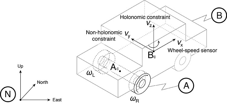
INS/GNSS/WSS/VDC Integration. For the vehicle in motion, we developed a model consisting of a WSS measurement in the along-track direction, a non-holonomic constraint resisting lateral sliding, and a holonomic constraint on vertical movement (see FIGURE 4).
The INS/GNSS/WSS/VDC integration using the EKF consists of the process model and the measurement models.
FIGURE 4. The measurement model consisting of the WSS measurement in the along-track direction (vx), non-holonomic constraint resisting lateral sliding (vy), and holonomic constraint on vertical movement (vz). N is the navigation frame, Ac is the rear-axle center point and Bc is the center point of the body-fixed frame. (Image: Authors)
INS/GNSS/SMC Integration. The static mode constraint provides zero-velocity measurements to the EKF measurement update to mitigate position error propagation. We use SMC only when it is known that the vehicle is not moving; for example, when the vehicle is in the parking gear.
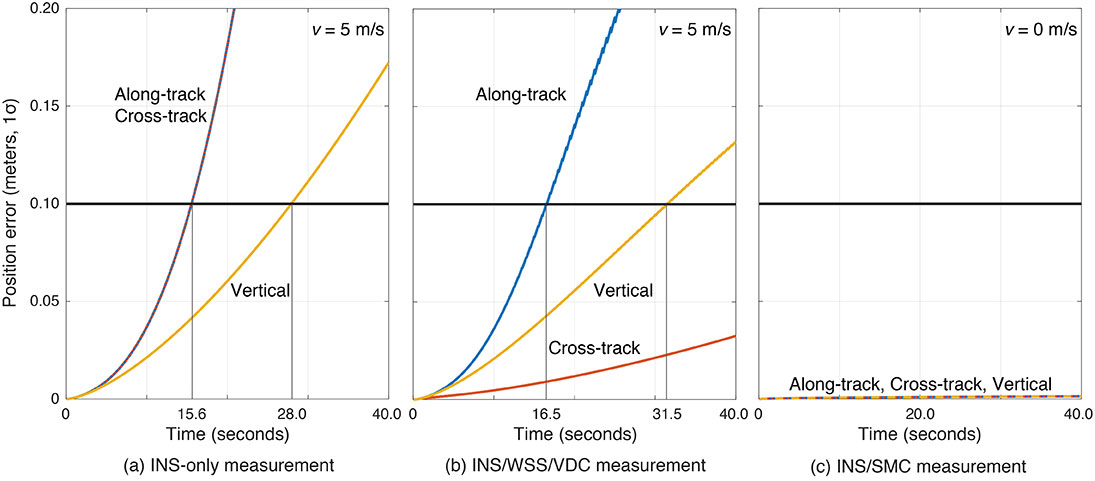
Error Propagation Analysis. We tested the time from perfect initialization to when position error exceeds 0.1 meters in GNSS-denied environments. FIGURE 5 shows the error growth in the along-track (x), the cross-track (y) and the vertical (z). The error specifications for a STIM300 tactical-grade IMU are used in this analysis. The standard deviation of the WSS measurement noise is assumed to be 0.05 meters per second, and the standard deviation of the movement constraint violations is 0.001 meters per second. The vehicle is moving at 5 meters per second except when we test the SMC.
The INS can coast 15.6 seconds before the position error standard deviation exceeds 0.1 meters in both the along-track and the cross-track directions (see FIGURE 5a). The INS/WSS/VDC can coast 16.5 seconds in the along-track direction, and significantly more than 40 seconds (the simulation duration) in the cross-track direction (see FIGURE 5b). In static mode, INS/SMC estimate errors do not grow with time in any direction, as expected (see FIGURE 5c). In GNSS-denied environments, the non-holonomic constraint suppresses the cross-track position error, but the WSS measurement hardly affects the along-track position error. The SMC works perfectly, but the usage is limited to when the vehicle is known to be stationary.
FIGURE 5. The vehicle position error growth vs. time in the along-track (x), cross-track (y) and vertical (z) directions. Each graph represents the navigation system introduced in the multi-sensor integration section. The vehicle is moving at 5 meters per second (a and b) or 0 meters per second (c). (Image: Authors)
SIMULATION SCENARIO
We imagine a future driverless-car mission scenario in which multi-sensor navigation systems are practicable. To minimize congestion in a city, autonomous vehicles will be held outside the urban core when not in use. In the clear open-sky environment, a vehicle in a parking lot completes GNSS initialization using the INS/GNSS/SMC system. Once requested for action, the vehicle departs for the city from the parking lot, and the motion of the vehicle improves alignment by the INS/GNSS system. Safe navigation can be ensured using the system to provide continuity under overpasses and bridges in the open-sky environment. Upon entering the urban core, navigation becomes more dependent on the INS/WSS/VDC system.
A reasonable numerical target for differential GNSS initialized position error is 0.02 meters, and for the INS alignment yaw angle error 0.1 degrees.
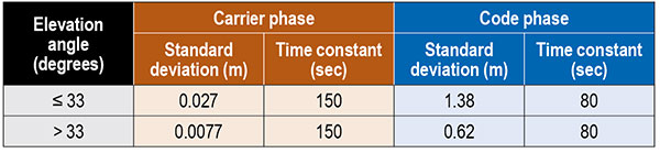
Local GNSS multipath errors from nearby vehicles will vary with the satellite elevation angle. Prior experimental results show that lower elevation-angle satellite signals (below 33 degrees) are much more likely to be impacted by multipath than higher ones (see TABLE 1).
Table 1. The nominal GNSS multipath error values in the simulation.
INITIALIZATION AND ALIGNMENT
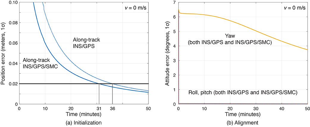
Initialization takes place in a parking lot with a clear sky view. A vehicle is in the parking gear, enabling SMC to be applied. FIGURE 6a shows a typical example: with INS/GPS/SMC, system initialization takes about 31 minutes, and with INS/GPS, about 36 minutes. Therefore, SMC does speed up GPS initialization, although the improvement is modest.
The yaw angle is not aligned during the initialization, but roll and pitch are immediately aligned (see FIGURE 6b). Earth’s gravity affects roll and pitch angle alignment but not yaw angle.
Yaw angle alignment cannot be performed when the vehicle is stationary or moving with constant velocity. Accelerated motion, either straight or turning, is required.
FIGURE 6. (a) Comparisons of initialization time between INS/GPS and INS/GPS/SMC in an open-sky environment. The INS/GPS/SMC system initializes rapidly. (b) Transitions of roll, pitch, yaw alignment during the initialization. Yaw angle alignment cannot be performed when the vehicle is stationary. (Image: Authors)
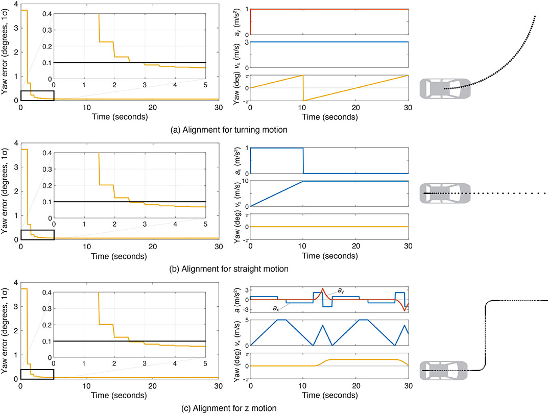
FIGURE 7 shows the behavior of the yaw angle error standard deviation using the INS/GPS system when centripetal (see FIGURE 7a) or tangential (see FIGURE 7b) acceleration is applied. The yaw angle can be aligned in a couple of seconds for either type of acceleration. To represent typical initial motions of self-driving cars, we model a parking-lot departure via a “Z”-shaped path. In this scenario, the yaw alignment error reaches 0.1 degrees within a couple of seconds (see FIGURE 7c).
FIGURE 7. The behavior of yaw angle error when centripetal (a) or tangential (b) acceleration is applied; (c) shows the behavior while following a z-shaped path. The yaw angle can be aligned in a couple of seconds in each case. (Image: Authors)
EVALUATION IN URBAN ENVIRONMENTS
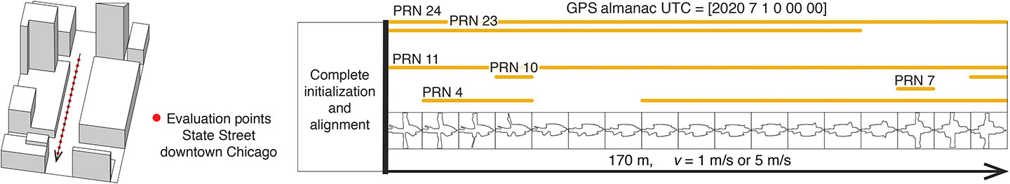
After initialization and alignment in the open-sky environment, we simulated the vehicle traveling into the urban core. The urban environment in our study is 3D-mapped State Street in Chicago, which runs north-south and transits from low-rise neighborhoods to central downtown. We selected one congested section surrounded by tall buildings and computed the position error standard deviation along the path. The evaluation points are at 10-meter intervals over a total distance of 170 meters. The yellow lines in FIGURE 8 denote the visible satellites, identified by their pseudorandom noise (PRN) code numbers, at each point. We assume for convenience that the INS/GPS system is initialized and aligned at the first evaluation point. In reality, we would expect a degraded initial condition because we are starting the simulation in an urban canyon.
FIGURE 8. Evaluation points and PRN numbers of visible satellites at each point. (Image: Authors)
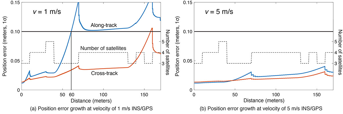
In the first simulation, the car equipped with the INS/GPS system moved either 1 or 5 meters per second. The y-axis in FIGURE 9 represents the position error standard deviation, and the x-axis represents the distance in meters. The dotted line expresses the number of visible satellites. The error when the vehicle velocity is 1 meter per second exceeded the maximum allowable position error standard deviation of 0.1 meter, at the distance of 60 meters. However, when the velocity was 5 meters per second, the maximum allowable position error standard deviation was never reached. It is also clear from the figures that error propagation is significantly affected by the number of visible satellites.
FIGURE 9. A comparison of position error growth between velocities of 1 meter per second and 5 meters per second. (Image: Authors)
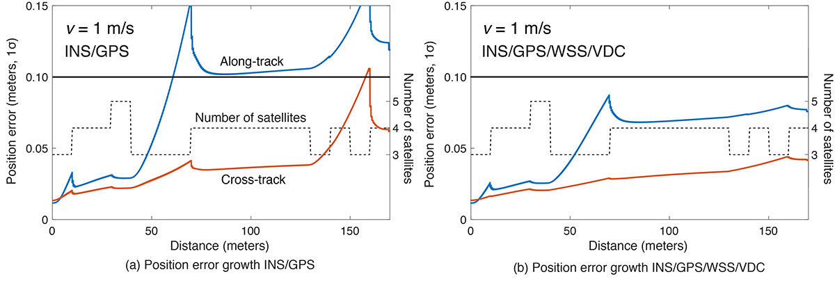
In the second simulation, we compared two different navigation systems, INS/GPS and INS/GPS/WSS/VDC. The vehicle moved at 1 meter per second in the same urban environment. The INS/GPS/WSS/VDC system does provide relief, but the error propagation is still clearly affected by the number of visible satellites (see FIGURE 10).
FIGURE 10. A comparison of position error growth between the INS/GPS and INS/GPS/WSS/VDC systems for a velocity of 1 meter per second. (Image: Authors)
In GNSS-challenged environments, INS error propagation is a function of time. When a vehicle moves faster, it clears the blockage area more quickly, reducing the impact of INS drift — a function of time, not distance. In contrast, GNSS error is completely determined by location. Because INS error propagation depends on how long the vehicle stays in an area of GNSS outage, protection levels for trips through the same area will be different if the vehicle is smoothly cruising or gets stuck in a traffic jam.
CONCLUSION
To gain a better understanding of how long and under what local conditions multi-sensor integrated navigation systems can maintain fault-free integrity, we evaluated navigation positioning errors in 3D-mapped downtown Chicago. The system we developed consists of sensors with which self-driving cars would reasonably be equipped: GNSS, INS, WSS and dynamic constraints. We showed that INS/GPS position errors along the path depend very strongly on the vehicle’s speed. When the system is augmented with WSS/VDC, position errors are suppressed, but the error propagation is still strongly influenced by the number of visible satellites.
ACKNOWLEDGMENTS
The research described in this article is supported by the National Science Foundation. Figure 1 was created by Alexis Arias of the Landscape Architecture + Urbanism Program at the Illinois Institute of Technology (IIT). The authors greatly appreciate the advice and help of Nilay Mistry from that program.
This article is based on the paper “Evaluating INS/GNSS Availability for Self-Driving Cars in Urban Environments” presented at ION ITM 2021, the virtual 2021 International Technical Meeting of The Institute of Navigation, Jan. 25–28, 2021.
KANA NAGAI is a Ph.D. candidate and research assistant in mechanical and aerospace engineering at IIT.
MATTHEW SPENKO is a professor of mechanical and aerospace engineering at IIT. He earned his M.S. and Ph.D. degrees in mechanical engineering from the Massachusetts Institute of Technology.
RON HENDERSON is a professor and director of the Landscape Architecture + Urbanism Program at IIT. He earned his Master of Landscape Architecture and Master of Architecture from the University of Pennsylvania.
BORIS PERVAN is a professor of mechanical and aerospace engineering at IIT. He earned his M.S. from the California Institute of Technology and Ph.D. from Stanford University.
A roundup of recent products in the GNSS and inertial positioning industry from the January 2022 issue of GPS World magazine.
Surveying
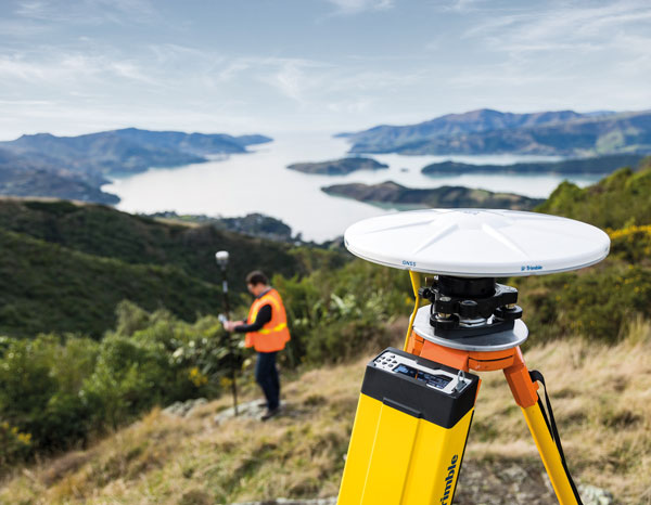
Base Station
Receives all available GNSS signals
Photo: Trimble
The Trimble R750 GNSS modular receiver is a connected base station for use in civil construction, geospatial and agricultural applications. The R750 provides high-accuracy base-station performance, giving contractors, surveyors and farmers more reliable and precise positioning in the field. The R750 also can be used to broadcast real-time kinematic (RTK) corrections for a wide range of applications, including seismic surveying, monitoring, civil construction, precision agriculture and more. Access to all available satellite signals provides improved performance and reliability when used with a Trimble ProPoint GNSS rover. ProPoint gives users improved performance in challenging GNSS conditions, with improved signal management.
Trimble, trimble.com
Flight Planning
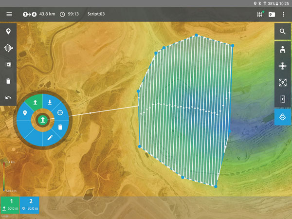
Updated for safer UAV surveying
Photo: Microdrones
The mdCockpit app was designed for professional drone users to make it easy to plan, monitor, change and control flights from an Android tablet. The updates in version 2021.3 include features that improve flight safety and give more options for surveying with an aim to deliver a premier solution for planning, monitoring, adjusting, analyzing and controlling professional drone flight missions from a tablet. Updates include an improved flight editor, flight data collection and drone configuration. Drone pilots can download mdCockpit through the Google Play store.
Microdrones, microdrones.com
OEM
LTE Module
With 2G fallback for Latin America
Photo: Telit
The LE910S1-ELG LTE Cat 1 module is designed for internet of things (IoT) applications in Latin America that need a combination of performance, affordability and voice support in a compact form factor. It provides 2G fallback, making it suitable for areas that have not upgraded to 4G. With an embedded GNSS receiver, the cost-optimized LE910S1-ELG is suitable for tracking applications such as fleet management, stolen-vehicle tracking and recovery, and other mobile IoT applications that need to maintain a reliable connection when moving around in a country, region or multiple regions. The power-saving embedded GNSS receiver enables the use of GNSS positioning even when the cellular modem is switched off.
Telit, telit.com
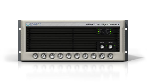
Flex Power
Capability now on constellation simulator
Photo: Spirent
A new positioning, navigation and timing (PNT) test capability commonly referred to as programmable power — or flex power — is available on the Spirent GSS9000 constellation simulator and can be applied to existing scenarios. Flex power is the reallocation of transmit power among individual signals in GPS satellites, providing a countermeasure against GPS jamming. Spirent simulators fully support programmable power for M-code, Y-code and C/A (coarse acquisition) code.
Spirent, spirent.com
GNSS Module
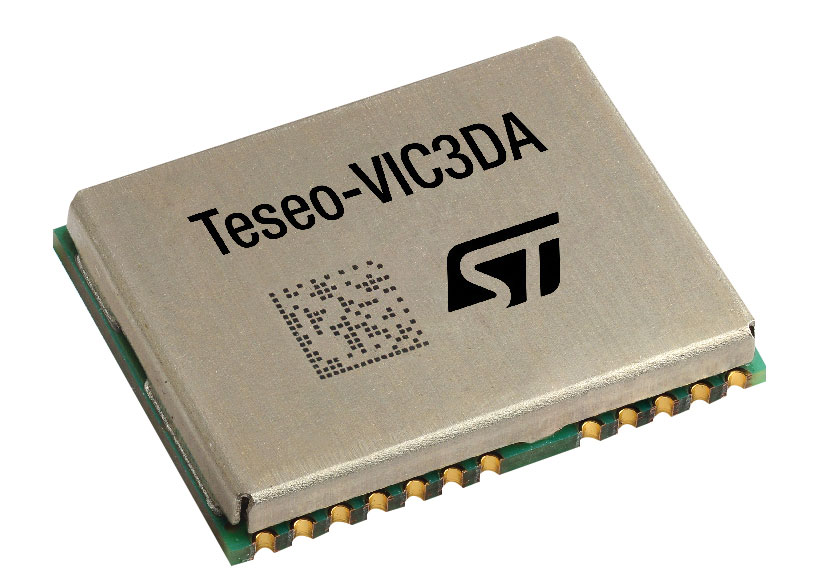
Automotive qualified with INS and dead reckoning
Photo: STMicroelectronics
The Teseo-VIC3DA is the latest member of the Teseo module family, designed for vehicle positioning. It combines the Teseo III GNSS integrated circuit with the 6-axis MEMS inertial measurement unit (IMU) and dead-reckoning software to provide super-high-resolution motion tracking for advanced vehicle navigation and telematics applications. Teseo III offers robust positioning capabilities by simultaneously receiving signals from GPS, Galileo, GLONASS, BeiDou and QZSS constellations. The module enables competitively priced in-car navigation, fleet management and insurance-monitoring applications.
STMicroelectronics, st.com
PNT Platform
Protects critical infrastructure from GNSS vulnerabilities
Photo: ADVA
The scalable aPNT+ platform meets the latest guidelines for resilient positioning, navigation and timing (PNT), providing end-to-end control and timing network visibility for robust protection against the catastrophic risks that PNT disruption poses to national security and essential assets such as power grids. Even without GPS or GNSS timing, the solution provides an intelligent, end-to-end self-recovery system designed around a three-fold framework, integrating multi-layer detection, multi-source backup and multi-level fault-tolerant mitigation.
ADVA, adva.com
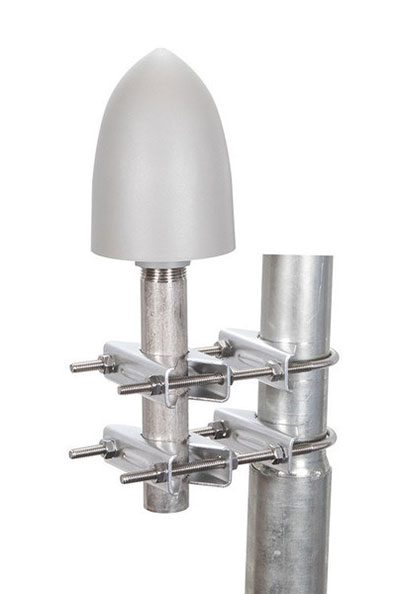
Timing Antennas
IP67-compliant for outdoor and marine environments
Photo: RadioWaves
A new series of GPS/GNSS timing antennas cover the L1 and L5 GPS bands, providing axial ratio and higher accuracy for the reception of satellite timing signals and reference frequencies for enhanced phase synchronization in precision network deployments. Their high gain, low noise figure of 2-dB and high out-of-band rejection allows for use of longer and cost-effective cables for easy and flexible installations. Built-in surge protection supports a wide range of GNSS including GPS, GLONASS, BeiDou and Galileo, as well as Iridium.
RadioWaves, radiowaves.com
Mapping
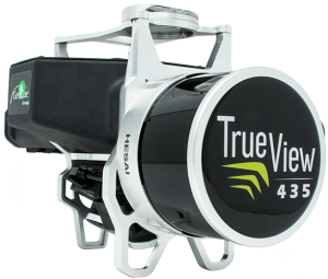
Imaging System
Designed for utility and infrastructure mapping
Photo: Geocue
True View 435 is an economical platform for utility-grade mapping, with superior ground-capturing capabilities for lightly vegetated areas. The next-generation compact 3D imaging system has the sensitivity needed for infrastructure mapping. Its position and orientation system is the Applanix APX-15, achieving accuracy of better than 5 cm RMSE and precision of better than 5 cm at 1 sigma.
GeoCue, geocue.com
Long-Range Scanner
Includes integrated GNSS receiver
Photo: Riegl
The VZ-2000i long-range 3D laser scanning system combines user friendliness with fast, accurate data acquisition. The flexible system includes an integrated GNSS unit for a high-accuracy real-time kinematic (RTK) solution. Other peripherals and accessories include a SIM card slot for 3G/4G LTE, WLAN, LAN, USB and other ports. A new processing architecture enables execution of different background tasks onboard in parallel to the simultaneous acquisition of scan data and image data, such as point-cloud registration, georeferencing and orientation via an integrated inertial measurement unit.
RIEGL, riegl.com
Transportation
Vehicle Antennas
Designed for Intelligent connected cars and trucks
Photo: Harxon
Two new GNSS antennas are designed for vehicles equipped with advanced sensors, controllers, actuators and other devices. They are enabled for intelligent information exchanges between the vehicle and everything (V2X), connecting autos with GNSS, 5G, Wi-Fi, ultra-wideband and more. The integrated antennas support dedicated short-range (DSRC) and cellular vehicle-to-everything (C-V2X) communication, embedding a premium GNSS antenna with high gain for consistent and reliable precise positioning service. They also allow for multiple input and output of data to achieve swift internet download speed in 5G networks.
Harxon, harxon.com
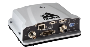
NVIDIA AV Support
Receiver now supported on autonomous platform
Photo: NovAtel
The PwrPak7-E1 GNSS receiver is now supported on the NVIDIA Drive Hyperion autonomous vehicle (AV) development platform. Selected for its robustness and precise position output, the PwrPak7-E1 will be offered with NVIDIA’s autonomous driving test fleets worldwide. Drive Hyperion is a fully operational, production-validated and open AV platform that reduces the time and cost required to outfit vehicles with autonomous driving and artificial intelligence (AI) features. The PwrPak7-E1 also is now compatible with NVIDIA’s DriveWorks v4 software release.
Hexagon | NovAtel, novatel.com
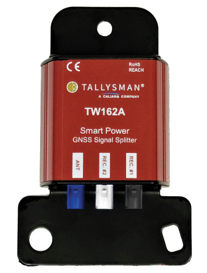
Splitter
Provides signals to two GNSS receivers
Photo: Tallysman
The TW162A automotive-grade smart power GNSS signal splitter supports the full GNSS spectrum: GPS/QZSS-L1/L2/L5, QZSS-L6, GLONASS-G1/G2/G3, Galileo-E1/E5a/E5b/E6, BeiDou-B1/B2/B2a/B3 and L-band correction service frequency band. It offers fail-over and fault-identification features. The splitter accepts power from all attached GNSS receivers; if one receiver fails, the next attached receiver automatically provides power to the splitter and antenna. If the antenna fails and does not draw current, all connected receivers will sense a current draw lower than 1 mA, indicating an antenna fault. The TW162A offers high performance in terms of noise figure, isolation and linearity.
Tallysman, tallysman.com
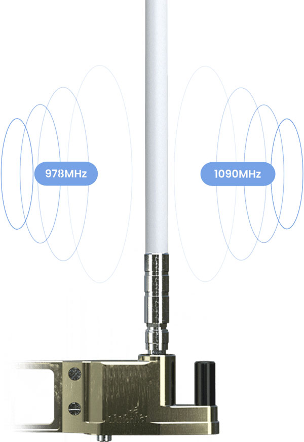
ADS-B Receiver
Enhances airport situational awareness
Photo: uAvionix
The pingStation 3 integrates 978 MHz and 1090 MHz ADS-B receivers, a GPS receiver, an antenna and a power-over-Ethernet (POE) interface into an easy-to-install, rugged weatherproof enclosure. With a selection of non-proprietary and industry-standard data interfaces, such as JSON and ASTERIX CAT 021, pingStation 3 is designed to integrate into a multitude of end-user applications, including airport displays, UAS Ground Control Stations (GCS), Unmanned Traffic Management (UTM) Solutions, and Flight Information Displays (FID). When paired with the VTU-20 airport vehicle ADS-B transmitter, pingStation 3 improves the situational awareness of ATCs and the safety of airport operations by reducing the risk of runway incursions.
uAvionix, uavionix.com
UAV
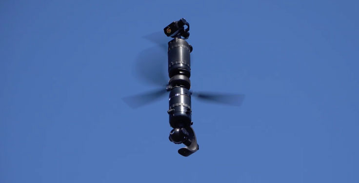
Defense UAS
Flexible UAV and control software combined
Photo: Ascent AeroSystems
Ascent AeroSystems’ Spirit coaxial unmanned aerial system (UAS) offers a versatile and durable system for mission-critical operations. With a modular, plug-and-play payload design, the Spirit’s open architecture allows operators to add or upgrade software to unlock new operating capabilities without the need to design or develop a new aircraft. Autonodyne’s additive software solution allows the Spirit to perform autonomous tasks either individually or as a team with multiple vehicles, from a single operator and control station.
Ascent AeroSystems, ascentaerosystems.com
Autonodyne, autonodyne.com
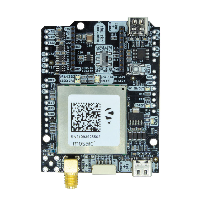
Evaluation Kits
Now include mosaic Septentrio modules
Photo: ArduSimple
Two Septentrio modules are being integrated into ArduSimple’s new evaluation kits — the mosaic-X5 GNSS module and the mosaic-H heading module. The new kits make resilient centimeter-level positioning easily accessible for testing and prototyping. ArduSimple’s kits provide triple-band real-time kinematic (RTK) GPS/GNSS as a plug-and-play solution for the most popular development platforms such as Arduino, STM Nucleo, Raspberry Pi, Ardupilot and Nvidia Jetson. It enables developers of robotics, UAVs and autonomous systems to try out mosaic, a unique module offering the latest high-performance GNSS positioning technology.
Septentrio, septentrio.com; ArduSimple, ardusimple.com
Geospatial Data
Drones as a service
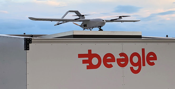
Photo: Beagle
A drone network solution offers on-demand imagery to customers in Germany at resolutions up to 50 times higher than available from commercial satellite data providers. The Beagle M drone and sensors can deliver image data at 1-cm per pixel many times faster than satellites and regardless of cloud coverage. The company’s charging hangars enable quick flights. After completing an autonomous inspection flight (up to 200 km on a single charge), the drone returns to its hangar where it charges for its next mission. The drone takes just 90 minutes to become fully charged, and can then advance to its next mission without any physical contact between operator and aircraft.
Beagle Systems, beaglesystems.com
Spirent Communications plc has chosen Navmatix s.r.o., a Czech-based company that provides cloud infrastructure for real-time data delivery, to provide cloud infrastructure for its GNSS Foresight service.
Spirent GNSS Foresight is a cloud-based service delivering real-time data on the availability and quality of GNSS signals. The solution accurately forecasts when and where GNSS positioning and navigation will be most reliable through a combination of high-definition maps and precise orbital modelling. This makes it possible to obtain a clear picture of the operating environment at a moment’s notice.
GNSS Foresight will ultimately allow unmanned vehicles, air taxis and drones to operate beyond-visual-line-of-sight (BVLOS) safely.
The GNSS Foresight service enables flight in challenging environments by calculating GNSS availability for every meter, every second, from 1-100 meters altitude, for up to three days into the future. (Image: Spirent Communications)
Navmatix will provide the cloud infrastructure required to deliver GNSS forecast data as real-time data via an API. Navmatix will be deploying full operational and developmental support, including hosting for collection and processing the GNSS forecast data through its content delivery network (CDN). The CDN allows the end user to efficiently query, comprehend and interact with the data. Navmatix will handle the foundational infrastructure of the project, a significant phase in expansion of the company as a whole.
“Spirent Communications are pioneers in GNSS test and assurance solutions, and the Spirent GNSS Foresight service expands our solutions to help autonomous systems reliably use GNSS,” said Jeremy Bennington, vic president of PNT Assurance. “Navmatix has built a framework that can deliver mission-critical services, which is also reliable and scalable. We’re excited to be partnering with Navmatix and look forward to growing Navmatix’s CDN to support the growth of Spirent GNSS Foresight solution throughout its complete lifecycle.”
Because of the amount of data generated, the architecture delivers a robust and sophisticated solution, according to Navmatix. Being entirely cloud based, it allows for continual updates and remote access. The cloud infrastructure will provide the tools necessary to deliver Spirent GNSS Foresight services to Spirent customers worldwide.
Navmatix offers managed infrastructure solutions for the operation, development and ongoing maintenance of GNSS services worldwide.