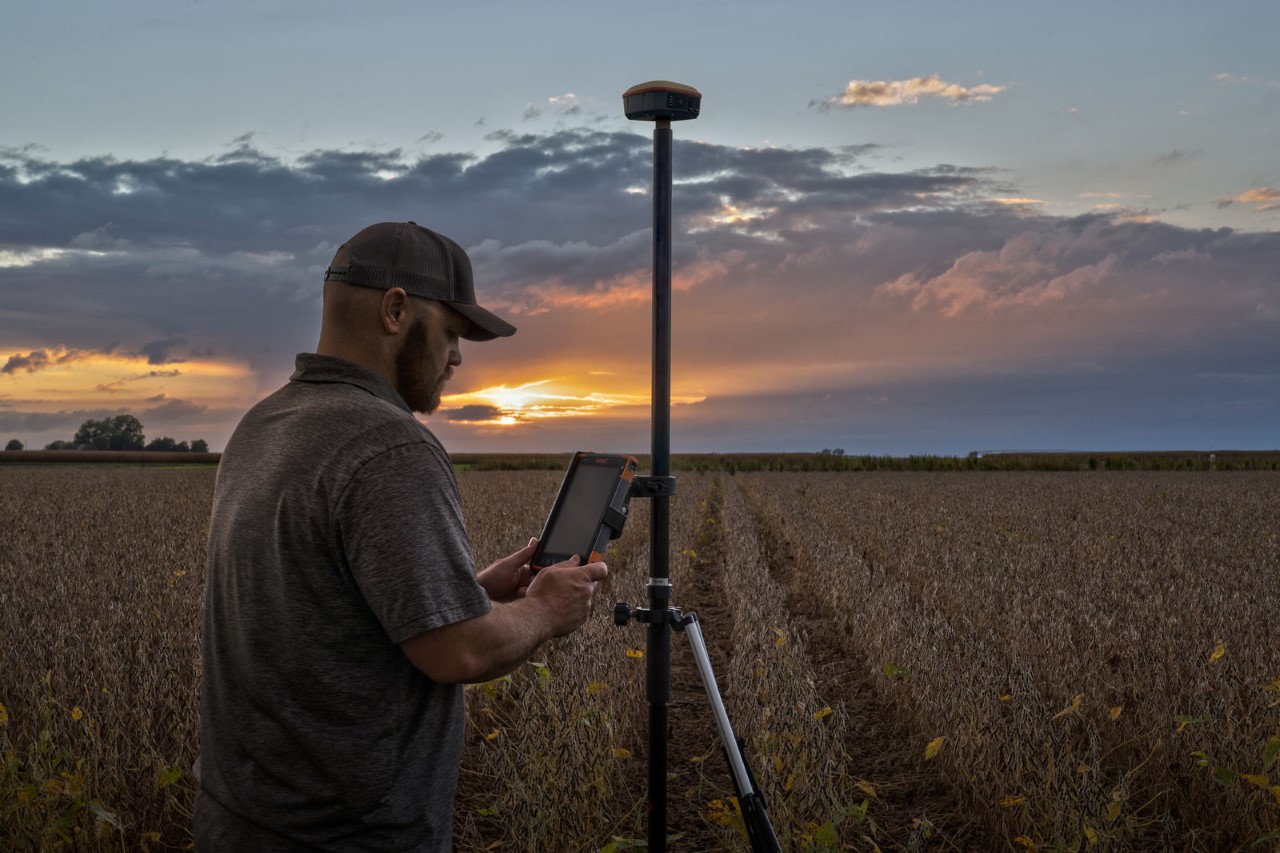
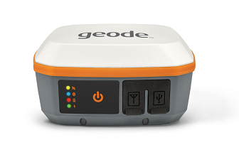
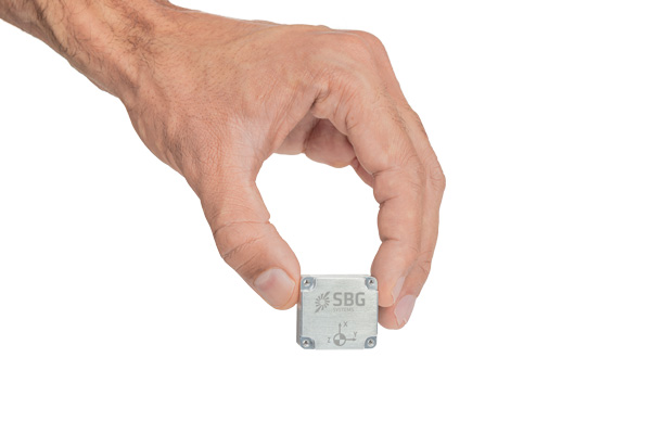
Juniper Systems has introduced the Geode GNS3 GNSS receiver, which allows users to collect real-time GNSS data with sub-meter, sub-foot and decimeter accuracy options.
With a scalable platform, users can purchase the level of accuracy they need now, while having the option to increase accuracy in the future.
“This new Geode offers expanded accuracy options to our users,” said John Florio, Geode product manager at Juniper Systems. “We set out to deliver a product that is scalable to our user’s needs. The GNS3 allows users to purchase a receiver that fits their accuracy needs at the moment, while still being able to unlock greater accuracy through subscriptions when that need arises.”
Photo: Juniper Systems
Available in both single-frequency and upgradable multi-frequency antenna configurations, users have the level of accuracy needed to get the job done. The Geode GNS3S offers superb sub-meter accuracy with a single-frequency antenna. The GNS3M allows for scalable accuracy; its multi-frequency antenna support all constellations on L1, L2 and L5 frequencies.
Multi-frequency signal tracking, together with Atlas L-band correction subscriptions, allow for up to decimeter accuracy. As with previous Geode devices, SBAS corrections are available for sub-meter accuracy in certain regions.
Both models also support local differential GNSS real-time kinematic (RTK) and continuously operating reference networks (CORS) through the Geode Connect NTRIP client.
“Providing Atlas corrections and scalable accuracy allows for the Geode to be used in new markets,” Florio said. “A few of these include water utility locating, agriculture and irrigation mapping, mapping projects in remote locations where other correction services are not available, and any other mapping need that requires a higher degree of accuracy.”
The Geode GNS3 offers flexible connectivity and can be used with Windows, Android, iPhone and iPad devices. A USB-C port allows for data transfer and fast charging and an antenna port allows for the use of an external antenna.
The Geode GNS3 GNSS receiver is now available worldwide.
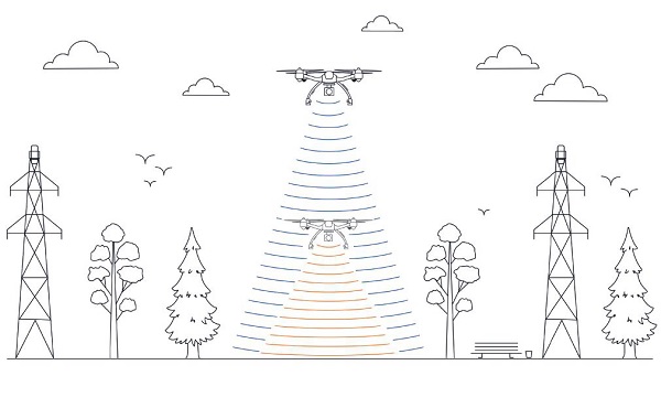
This image shows the effect of increased elevation on surface area and obstacle avoidance. (Image: Advanced Navigation)
By Simon Harris, Advanced Navigation
Lidar-based surveying is increasing in demand across a range of industries. Recent market analyses indicate that lidar surveying is a multi-billion dollar industry that is expected to deliver sustained growth for years to come. As lidar technology matures and performance increases, its range of use is broadening into surveying more complex and difficult terrain or at speeds and in environments previously unsuited to such technology. Naturally, increasing diversity and performance brings about demands for greater reliability, speed and accuracy whilst remaining within physical and regulatory limitations.
Keeping pace with market demands in UAV and rail sector lidar surveying is increasingly challenging and requires an evolving synthesis between the acquisition and processing of lidar and GNSS-INS georeferencing data. Companies such as Cordel and its subsidiary Nextcore are taking advantage of the latest technologies to develop systems that are setting new benchmarks in these sectors.
Benefits of Altitude, Faster Lidar and Precision INS
UAV lidar surveying is capable of high-resolution surveys of complex terrain, vegetated areas and in light conditions that may be unsuitable to photogrammetry. These qualities make it a preferred option in many applications. However, it must remain cost-competitive with alternative solutions to become widely adopted by the surveying industry.
Typical UAV lidar surveying is performed at ~40m AGL. This altitude commonly presents collision risks with terrain and vegetation and imposes limits where the topography changes dramatically, such as voids that increase AGL beyond acceptable limits. Higher altitude surveying, therefore, offers obvious advantages, but also deeply challenges lidar sensors and the INS. Any mismatch in operational performance and accuracy between these inevitably degrades survey quality and severely limits use of the system.
Nextcore accepted the challenge and set about developing a viable solution that could maintain a point cloud density of 200-500 points per m2 from a target altitude of 70 m. This equates to generating lidar point cloud data at millions of points per second. Achieving this required a GNSS-INS that provided suitably precise georeferencing data. Because survey data is derived from a source that is in constant motion in 3D space, the capability of the GNSS-INS is paramount in producing a digital twin of value and is critical to mission success.
After testing and evaluating various INSs from different manufacturers, Nextcore coupled its lidar with Advanced Navigation’s MEMs-based Certus Evo INS, which provides near-FOG performance and has a drift rate of 0.2 degrees/hour. This combination yielded exceptional results that allowed them to vastly extend the altitude ceiling to 120m while retaining consistent, accurate survey data.
“Operation at this altitude not only reduces the risk of collisions with trees, it enables surveyors to cover larger areas, greatly improving the solution’s efficiency,” said Ashley Cox, founder and COO of Nextcore.
Higher altitudes tend to increase the lidar swath width. The typical swath width at ~50m altitude is ~120m, depending on actual altitude and the resulting angle of incidence of lidar toward the edges of the swath. At 120m, a reliable swath width of 180m was achieved. This is a 50% increase over previous, equating to approximately 33% fewer flight-lines to survey a given area — a notable boost for productivity and efficiency to surveyors.
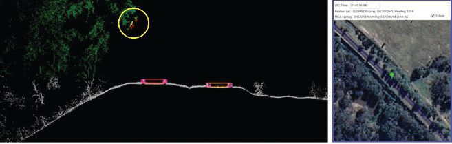
Example of rail track lidar showing encroaching vegetation, with associated map and location information. The yellow circle in the lidar data shows vegetation that is starting to intrude into the train’s path. (Images: Advanced Navigation)
Payload minimization also was a critical aspect in the search for an INS, as surveyors are always seeking longer flying time. This only can be achieved with a lighter technology stack payload. The team used an OEM version of the INS for a smaller form factor that could be integrated within a single ruggedized housing. This allows a design with greater strength, weather resistance and efficient payload setup.
“The industry is constantly seeking lighter payloads for longer flight times and to fit on smaller, safer UAVs,” Cox said. “Regulatory restrictions challenge the industry to meet certain specifications. The same is true for UAV lidar. We hit a ceiling. We need to be able to improve on that, although what we’re achieving now is a real game changer.”
The resulting survey material contains lidar point cloud data and the geo-referencing data from the INS. All data processing is performed post-flight to ensure the highest possible accuracy. PPK is used for correction of GNSS-INS position, roll, pitch and heading data. The processed INS data is then combined with the processed point cloud data to provide absolute position to the point cloud. This system realized consistent 30~40mm precision at 120m AGL. Nextcore has integrated the lidar and INS processing platforms to automate the synthesis of data sets, reducing the survey completion time. Depending on the survey’s size and complexity, this solution can process survey data into a 3D map within 30 minutes of mission completion.
Nextcore used a Certus Evo GNSS receiver, which internally uses the u-blox ZED-F9P chip. It logs GPS L1, L2, GLONASS L1, L2, Galileo GalE1, E5, and BeiDou B1, B2 frequencies at 8 Hz. It used the Kinematica correction service running a PPK filter.
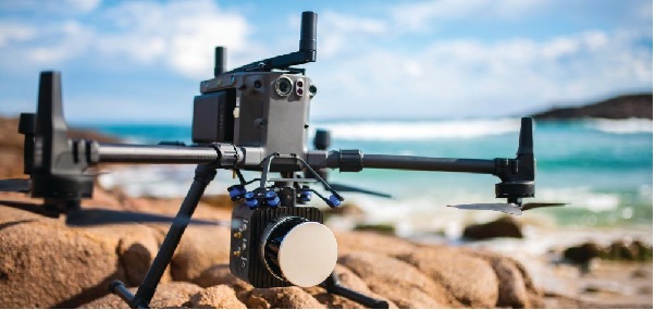
Lidar sensors have become light enough to mount on UAVs (Photo: Advanced Navigation)
Scanning Rail Corridors Super Fast
Aerial surveying is not the only environment to present challenges to lidar and INS.
Train-mounted lidar for automated track and rail corridor surveying is another burgeoning market. This application typically uses lidar and position data to detect and identify areas of the railway that require maintenance and, perhaps more importantly, preventive maintenance. Rail surveying presents unique demands, including operating at speeds of 160km/h (100mp/h) or more, maintaining position accuracy during GNSS outages and variable environmental conditions.
Land-based surveying provides flexibility for selecting an INS compared to aerial applications, as size and weight are usually irrelevant. Rail surveying also requires an INS that provides the necessary performance while tolerating vibration and erratic movement from junctions, points and signals, and be absolutely dependable in GNSS-denied situations. Cox’s team found that the greater accuracy and better drift stability of FOG INS over MEMS provided an ideal platform for generating reliable and accurate paths of train trajectory.
Cordel tested Advanced Navigation’s Boreas digital FOG INS as a potential solution. Testing was carried out using cars as a simulation, travelling complex routes in two directions then overlaying the lidar point clouds to check for discrepancies or unsynchronized areas. The results provided the confidence to put the Boreas into service.
Railways typically traverse deep cuttings, lengthy tunnels and other environments that disrupt GNSS. It is mission-critical that the INS can apply dead reckoning the instant GNSS is disrupted and maintain accurate position for the entirety of the outage. Reliable path and location data during GNSS disruptions is central to the viability of automated rail surveying. Blind spots or zones of unreliable route data cannot be tolerated by rail operators from safety, track availability and financial perspectives.
The Cordel AI lidar analysis system can be “tuned” to the required metrics and is capable of self-learning. The AI enables the system to pre-emptively identify and flag areas of concern before they become an actual problem or hazard. Examples include measuring track gauge and alignment, ballast distribution and coverage, and clearance between potential hazards to the train. The entire route is logged, creating a “Google map” of the railway that maintains a historical record of survey data each time the track is used.
Clients can then view a representation of the lidar data to get a clear understanding of any issues and how to respond before sending personnel or assets to a location. This enables intervention before safety is compromised or remedial works become large-scale and disruptive. As a result, rail service providers can maintain safer railways, deliver more reliable services, and minimize operating costs.
A roundup of recent products in the GNSS and inertial positioning industry from the April 2022 issue of GPS World magazine.
OEM
GNSS+5G Antenna
9-in-one combination antenna with dual-band GNSS
Photo: Taoglas
The Taoglas MA990 Guardian antenna is a 9-in-1 combination antenna with dual-band GNSS (L1/L2) and globally supported cellular (5G/4G). It has been designed to support emerging market demand for modules that cover specific 5G/4G bands. Two of its eight cellular MIMO antennas cover from 600 Mhz to 6,000 MHz, while another two are optimized for 3,000 MHz to 6,000 MHz to cover high-band 5G and C-band/CBRS applications. The customizable antenna is designed to operate on all global carrier networks and is future-proofed to work with the latest 5G routers on the market. Housed in a low-profile, robust, IP67-rated waterproof, adhesive-mount external enclosure, the MA990 is designed for space-constrained, mission-critical applications, including asset and vehicle tracking, first-responder vehicles and high-definition video sources such as surveillance cameras.
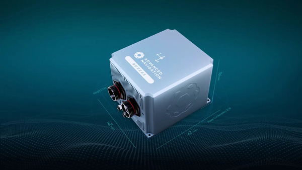
The Boreas fiber-optic-gyroscope inertial navigation system (INS) is an ultra-high accuracy, strategic-grade INS offering a reduction in size, weight, power and cost. It is based on Advanced Navigation’s new digital fiber-optic gyroscope (DFOG) technology. The Boreas is targeted at applications requiring always-available, ultra-high accuracy orientation and navigation including marine, surveying, subsea, aerospace, robotics and space. It delivers strategic-grade bias stability of 0.001 deg/hr. This allows it to achieve ultra-high roll/pitch accuracy of 0.005 degrees and heading accuracy of 0.006 degrees. The Boreas allows for full independence from GPS with dead-reckoning accuracy of 0.01% of the distance traveled with an odometer or Doppler velocity log. In addition, the Boreas features ultra-fast gyro compassing, taking only two minutes to acquire heading in both stationary environments or on the move. Gyro compassing allows the system to determine a highly accurate heading of 0.01 degrees secant latitude without relying on magnetic heading or GPS.
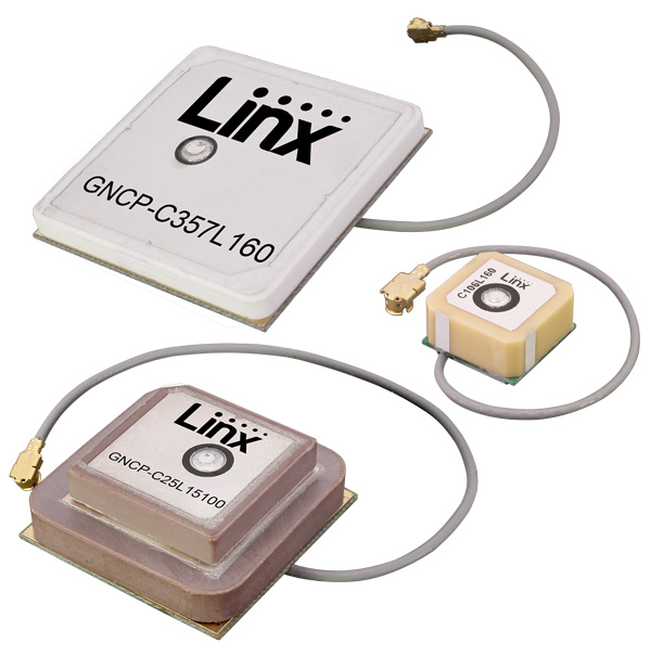
Seven new GNSS active ceramic-patch antennas support global GNSS applications including GPS, Galileo, GLONASS, BeiDou, NavIC and QZSS systems in the L1/E1/B1, L2/E5/B2B, and L5/E5/B2A bands. Each antenna integrates a high-gain low-noise amplifier (LNA) and right-hand circular polarization (RHCP) to provide a high-performance solution for GNSS signal reception. Each active GNSS antenna has either a 60-mm or 100-mm coaxial cable terminated in a MHF1/U.FL-type plug (female socket) connector. They also meet the need for multi-band L1/L2, L1/L5, and L1/L2/L5 GNSS offerings.
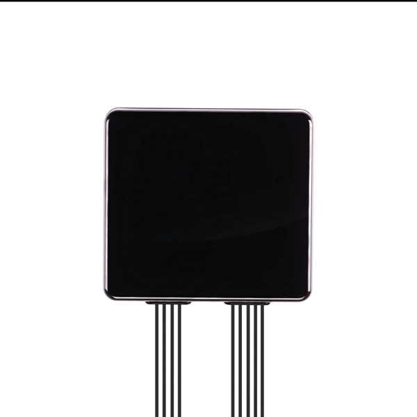
The Pulse-40 inertial measurement unit (IMU) is a tactical-grade IMU designed for high performance in harsh conditions but miniaturized for applications where precision and robustness matter in all conditions. Use cases include warfare systems, satellite communications, robotics, lidar devices, gimbals, cameras and inertial navigation systems (INS). The Pulse-40 IMU provides six degrees of freedom. It integrates micro-electromechanical (MEMS) three-axes accelerometers and gyroscopes in a unique redundant design that allows the device size to shrink while pushing performance to its maximum. Among the performance specifications, the Pulse-40 features excellent gyro and accelerometer bias instability of 0.8°/h and 6 µg respectively, enabling long dead-reckoning and maintaining excellent heading performance. With sensors featuring extremely low vibration rectification error (VRE), the Pulse-40 can sustain high vibration environments, up to 10 g root-mean-squared. An embedded continuous built-in-test ensures data reliability during operation, a key parameter for critical applications. Features include 12 grams, 0.3W power consumption; ultra-low noise gyro (0.08°/√h) and excellent gyro bias instability (0.8°/h); high-precision accelerometers (6 µg); MIL-STD 810-qualified for shocks and vibrations; high bandwidth (480 Hz) and high data rate (2 KHz); highly tested and calibrated from –40° C to 85° C; and no export restrictions.
Adds online services for field surveying and mapping
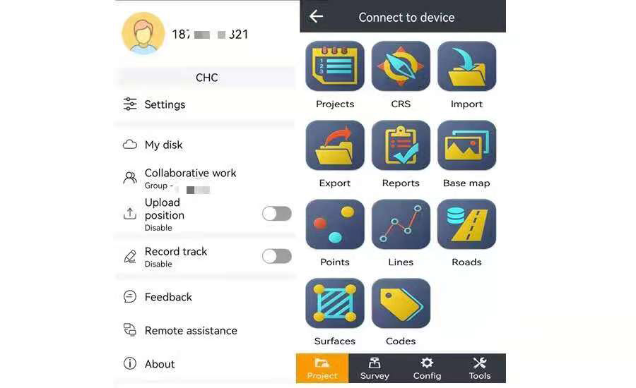
Photo: CHC Navigation
LandStar version 7.3.7 adds cloud-based services and remote support features to simplify surveyors’ daily tasks. Online data storage and file sharing greatly facilitates interactions within a company and between field operators. LandStar 7’s remote assistance feature allows support personnel to take control of the field crew’s devices. Users simply provide a remote code to grant control of their data controller and be guided efficiently to the solution. The new version of LandStar 7 further improves support for CAD files and operates faster when importing 20MB DWG or 200MB DXF basemap files. Users can directly click on points, lines and blocks to stake out. In addition, object symbols and colors are displayed in the same way as in the original CAD design, making it easier for users to identify them.
Uinta is now available for devices running on Android. This is particularly valuable for workers who prefer to use an Android tablet or smartphone as a data collector. Uinta’s intuitive and customizable user workflow makes land measurement and asset mapping easier for data collection in the field. Uinta can now be used on a range of smartphones and tablets, including Juniper Systems’ Cedar CT8X2 and Mesa 3 rugged tablets running on Android. When using Juniper’s Geode GNSS receiver and running Uinta on an Android phone or tablet, users create a total mapping solution. They can collect high-accuracy GNSS data on the Geode, record the data in Uinta software, and see the data on a mobile or tablet. The intuitive software includes project templates that can be modified to meet individual project needs. Uinta is commonly used in utility mapping; commercial and agricultural irrigation; industrial asset inspections and rounds; and numerous environmental sciences in forestry, wetlands, wildlife and vegetation mapping.
Visualize the present and simulate the future of Scottish cities
Photo: Bluesky
Scottish cities Edinburgh and Glasgow have been added to the growing coverage of MetroVista 3D city models. The data is available as ultra-high resolution 5-centimeter aerial photography with 16 points per meter (ppm) lidar. The data also is being processed to create a fully rendered mesh model suitable for use in a range of GIS, CAD and modeling software packages Acquired using the Leica CityMapper aerial sensor that simultaneously captures vertical and oblique imagery together with high-point density lidar, MetroVista data is becoming increasingly popular for smart city applications. Providing a geographically accurate and detailed 3D representation of the urban environment, MetroVista data provides insight for applications such as urban design, defense and security modeling, insurance assessments and utility and telecom planning.
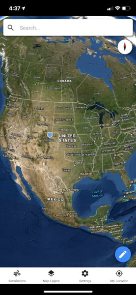
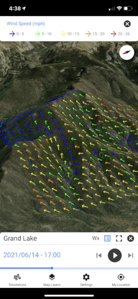
WindNinja is a high-resolution wind modeling app created for firefighters who need to quickly compute and visualize wind direction and speed simulations. The simulations provide them with situational awareness, help keep them safe, and help them conduct work such as burnout operations. The mobile app, developed using ArcGIS AppStudio from Esri, provides high-resolution, near-surface wind forecasts that include wind speeds and directions displayed on a map. The user selects an area of interest of 50 square kilometers or less, names the simulation, chooses a forecast duration of up to 15 hours, selects whether to receive an email or SMS notification when the simulation is ready to view, and then submits the request. The user also can select from a variety of basemaps and turn on data layers — vegetation, atmospheric, oceanic, land-surface imagery — collected by NOAA satellites.
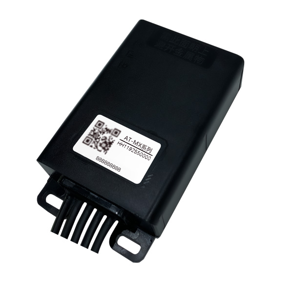
Intelligent control system meets urban transport requirements
Photo: Xiaoan Technology
The AT-MX intelligent control system for shared electric bicycles uses the latest ultra-low-power u-blox M10 GNSS technology to enhance the positioning performance of their fleet for improved compliance with increasingly stringent Chinese policy requirements. The growing popularity of shared micromobility solutions for short-distance urban travel has led municipal authorities around the world to introduce new legislation to mitigate their perceived negative impacts, for instance, with restrictions on where users can drive and park their vehicles. Meanwhile, vehicle operators and maintenance personnel need to efficiently locate vehicles requiring maintenance and gather reliable vehicle usage data to balance bicycle placement and operational safety. Enforcing regulatory compliance and optimizing operations both require the safe, accurate and efficient bicycle positioning solutions.
Ensures safe operations through reliable, robust and continuous positioning
Image: Hexagon
SPAN technology delivers a deeply coupled GNSS and inertial navigation system (INS) that provides robust, reliable and continuous centimeter-level positioning for operators to maintain safety and maximize uptime. Now available for the dynamic positioning of vessels, the GNSS+INS solutions can bridge outages in GNSS tracking and through short periods of radio-frequency interference, jamming or spoofing. It provides vessels with an added layer of resiliency and achieve continuous centimeter-level accuracy across all conditions. SPAN GNSS+INS technology is compatible with commercial inertial measurement units (IMUs) and scalable with the LD900 GNSS receiver, Quantum visualization software and APEX correction services. Features include continuous centimeter-level positioning made more robust and reliable through enhanced GNSS tracking and deep coupling of inertial measurements; rapid reacquisition of GNSS signals after outages or interruptions through a deep coupling process; constant monitoring of GNSS absolute positioning combined with heading, velocity and attitude measurements; and added positioning redundancy with system robustness against potential signal outages, interference or disruptions.
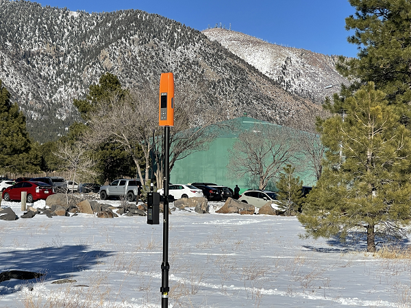
Ibtechar, one of Qatar’s top providers of practical innovation and turnkey solutions, has developed a drone tracker and a GPS-based system that ensure the safety and security of critical infrastructure, VIP residents, national borders, and military facilities. The customized solution is made by a Qatar-based team of researchers and technologists with extensive knowledge and expertise in applied research and counter-drone systems. It aims to secure airports, power lines, and other vital assets that can be targets for drone attacks. Prototypes have gone through 487 flight tests in 19 locations, as well as 676 drive and walk tests. Features include compatibility with GPS, GLONASS and BDS; real-time tracking, popup notifications and SMS alerts; smart geo-fencing; drone whitelists/blacklists; base-station triangulation (cell ID); IMU, tilt, vibration sensor, and NFC; and offline mode. The new tracking system can identify the operating drones by displaying the drone itself, its serial number, the commercial frequency used, and motion details (speed, altitude, azimuth, path, etc.).
DroneDeploy lets users capture, process and analyze data in one platform. Users can create high-resolution 2D and 3D interior and exterior maps and models accurate to between 1 cm and 5 cm. It is designed for individuals, teams or enterprises and is suitable for all use cases and industries. However, primary markets include agriculture, construction, mining, energy, roofing and inspection. Features include Mobile Flight App to capture images directly from
an iOS or Android device; Live Map to create real-time, sharable
2D maps; Autonomous Flight to preprogram routes; as well as
360 Walkthrough for a 360-degree, virtual tour through a 3D model of a site. Industry-specific features are available, such as Plant Health to help farmers measure crop health and viability.
Bad Elf has introduced a base/rover feature built upon its Bad Elf Flex GNSS receiver. The new base/rover feature brings affordable centimeter-level accuracy to surveyors and geospatial professionals working anywhere in the world.
The solution consists of two Flex GNSS receivers and two UHF radios, allowing customers to perform high-accuracy field data collection in areas where traditional real-time kinematic (RTK) corrections or cellular coverage is not available. Existing Flex customers can upgrade by adding Flex radio kits.
Bad Elf designed the base/rover feature with emphasis on accuracy, affordability and versatility. The Bad Elf Flex enables reliable data collection either as a standalone receiver or paired with apps on iOS or Android phones and tablets. A checklist-based workflow ensures consistent results and eliminates many common issues associated with setup and deployment of a base/rover solution.
Photo: Bad Elf
“The Bad Elf app walks the user through these steps and more, and it doesn’t let the project proceed until each checklist is complete,” said Larry Fox, vice president of Marketing and Business Development at Bad Elf. “The automated checklists simplify every process, so that geospatial professionals and surveyors of every experience level get reliable results.”
The base feature requires only one Flex Extreme and a radio kit. Customers may choose to use either Standard or Extreme Flex with a radio kit for rovers. Using Flex Standard and one daily token provides access to the rover feature.
Bad Elf’s flexible hardware-as-a-service model provides a mechanism for customers to further reduce the capital cost of a complete base/rover system. In addition, customers can deploy multiple rovers in either configuration for larger projects.
“For about one-third of the purchase price of competing products available today, our base/rover feature makes survey-grade one-centimeter accuracy a reality worldwide,” said Fox. “And our pay-as-you-go Flex Token model dramatically reduces operating expenses by allowing users to activate — and pay for — just the service levels needed on a given day.”
Complete base/rover kits are available immediately, along with à la carte options for existing Flex customers. The Flex base/rover solution is compliant with FCC operating standards in the United States. Bad Elf provides customers with complete instructions for acquiring a radio operator license and call-sign designation.
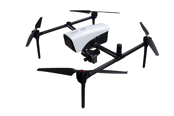
ComNav Technology has released a powerful and reliable UAV aerial mapping solution capable of centimeter-level positioning, providing high-precision photos and data for mapping professionals.
Based on the company’s K8 platform, the package consists of an E300 real-time kinematic (RTK) drone, flight-control software and an optional camera.
Featuring high accuracy, strong compatibility, long endurance, high performance and an easy workflow, the E300 drone package can meet the requirements of many different applications, including topographic survey, urban construction, forestry investigation, emergency rescue, 3D modeling, mining and surveying.
High Accuracy. The E300 RTK drone is embedded with a high-precision K8 GNSS module that supports GPS L1/L2/L5, BeiDou B1/B2/B3/B1C/B2a, GLONASS L1/L2, Galileo E1/E5-a/E5-b/AltBOC/E6 and QZSS L1/L2/L5. With Quantum III technology, the K8 GNSS module provides reliable and stable RTK positioning results.
The professional post-processed kinematic (PPK) software Compass Solution supports the full-constellation calculation, providing accurate positioning results.
RTK/PPK provides dual backup, one as a failsafe for another, to ensure acquisition of data. The built-in antenna further increases precision of photo position. EVENT synchronization technology can reduce camera trigger error and ensure high performance of the solution.
With its intelligent recognition algorithms, the E300 is able to capture high-resolution images consistently even in complex environments.Moreover, the E300 has a multipath redundancy design with key modules for safety.The solution can provide centimeter-level positioning results without ground control points, saving time.
Compatibility. Featuring a carrying capacity of 3 kg, the E300’s payload bay is compatible with a wide range of cameras, including C20, C50, LiAir VH2 and others. Payloads can be quickly and easily swapped in the field for maximum versatility.
Besides supporting standard NTRIP protocol, the E300 is compatible with all brands of base stations and continuously operating reference stations.
Long Endurance. The E300 is characterized by an ultra-efficient aerodynamic design. It reaches a 60-minute flight time without payload and 50 minutes with a basic payload, covering areas with a maximum 10-km radius per flight. In one flight, the E300 can map about 0.62 km² in 1.5-cm/px ground sample distance with one battery.
The E300 RTK drone features a simplified design for easy and rapid assembly within minutes while providing excellent stability and vibration resistance.
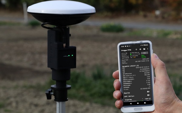
BizStation, a database company based in Japan, and u-blox have announced a highly accurate, compact and low-cost high-precision positioning solution for markets in East Asia and Oceania.
Featuring two u-blox modules, the solution delivers centimeter-level positioning accuracy where mobile network service is unavailable, including in maritime offshore surveying, agricultural and industrial vehicle guidance, and UAVs.
BizStation’s precise point positioning (PPP) system covers all territories served by Japan’s Quasi-Zenith Satellite System (QZSS) MADOCA correction service.
The solution leverages the strengths of two u-blox components. The first, a u-blox ZED-F9P multi-band high precision GNSS receiver module, is at the heart of BizStation’s DG-PRO1RWS GNSS receiver.
The second, a u-blox NEO-D9C correction-data receiver module specific to Japan, enables their virtual reference station to receive data on the QZSS L6E-band used by MADOCA.
The PPM (PPP positioning by MADOCA) Android application developed by BizStation then determines the location of the tracked device using the high-precision positioning data transferred via Wi-Fi from BizStation’s DG-PRO1RWS GNSS receiver as well as GNSS correction data from the virtual reference station. The PPM application performs all required calculations using the MADOCA positioning library developed by NEC Solution Innovators Co., Ltd.
The high-precision GNSS solution can be deployed either using a static or a mobile virtual reference station for a wide range of applications such as agriculture, drones, motor sports or surveying systems.
Trimble announced today that it has entered into a definitive agreement to sell its Time and Frequency, LOADRITE, Spectra Precision Tools and SECO accessories businesses to Precisional LLC, an affiliate of The Jordan Company (TJC).
The divestiture is in line with Trimble’s strategy to focus on areas core to its long-term growth and strategic product roadmap. The global transaction is subject to a number of customary closing conditions and is expected to close in the second quarter of 2022. Financial terms were not disclosed.
“We are continually evaluating our product portfolio as we work on the execution of Trimble’s Connect and Scale 2025 strategy,” said Rob Painter, president and CEO of Trimble. “Trimble is focusing its efforts on the company’s connected industry platforms and digital transformation capabilities, making Precisional and TJC an ideal fit for the growth of the businesses.”
TJC, a private equity firm, is completing the acquisition in partnership with industry executive Drew Ladau to form Precisional LLC, a global platform focused on precision measurement and data solutions driving efficiencies in demanding infrastructure end markets.
“The Trimble businesses, which will join Precisional, have a long heritage of innovation, and each is a leader in the markets it serves,” said Drew Ladau, CEO of Precisional. “I’m excited to build upon this strong foundation alongside the dedicated employees that have served their customers so well over the years. In addition, we plan to accelerate the pace of innovation and growth with the focus of resources and investment on these core businesses supported by TJC.”
“The acquisition of four industry-leading businesses from Trimble by Precisional forms the foundation of a new platform focused on precise measurement and analytical insights to improve productivity across a broad range of applications that rely upon accuracy and reliability,” said Erik Fagan, partner at TJC. “By supporting existing management to make investments in Precisional’s operations and product development to integrate precision measurement with data solutions and enhanced connectivity, we intend to accelerate growth opportunities while also pursuing synergistic acquisitions.”
The Time and Frequency products use the accuracy of GNSS clocks to provide precise time, synchronization and frequency reference signals for many industries and applications. Communication systems, data centers, financial networks, utilities, factory automation, security and other infrastructure rely on precise timing for synchronization and operational efficiency.
The Spectra Precision Tools business designs and manufactures high-quality leveling, positioning and alignment instruments used for general, exterior and underground construction. The instruments incorporate laser and optical technology for general contractors and specialty contractors serving large and small commercial jobsites as well as residential builders and remodelers.
The LOADRITE business offers accurate scales for loaders, excavators, conveyor belts, tractors, refuse trucks and forklifts that connect with payload-reporting and monitoring systems for the waste, quarry and aggregates industry. The products improve user efficiency by weighing products while they are on a vehicle or belt, eliminating the need for a separate trip to a fixed-scale location.
The SECO business designs and manufactures a wide variety of accessory products used in conjunction with surveying and construction instruments. The portfolio of accessory products includes tripods, telescopic poles, prisms, carrying cases, GPS antenna poles, safety vests and leveling rods.
LOADRITE, Spectra Precision Tools and the SECO businesses have been reported as part of Trimble’s Buildings and Infrastructure segment. The Time and Frequency business has been reported as part of Trimble’s Geospatial segment.
Orrick acted as legal advisor and Lincoln International acted as financial advisor to Trimble. Mayer Brown acted as legal advisor and BMO Capital Markets acted as financial advisor to TJC.
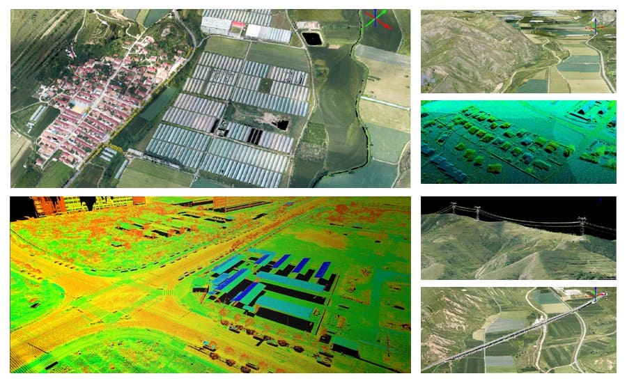
Both lightweight, compact airborne laser scanners are easily installed on various UAV platforms or small survey aircraft and helicopters. They are adapted to high-density point corridor mapping applications, day or night, under leaf-on and leaf-off conditions or with dense vegetation to provide reliable results.
“Nowadays, it is critical to obtain the highest data quality for the majority of aerial survey projects,” said Andrei Gorb, product manager of CHC Navigation’s Mapping and Geospatial Division.
Combining with industrial-grade GNSS receivers and high-precision inertial measurement units (IMUs), the AA1400 and AA2400 provide 2 to 5 cm survey-grade accuracy. They also integrate Riegl’s VUX lidars with waveform-lidar technology, allowing echo digitization and online waveform processing.
“Multi-target resolution is the basis for penetrating even dense foliage,” Gorb said. “The continuously rotating polygonal mirror wheel enables scanning speed of up to 400 lines per second, allowing for effective coverage of large areas when used from fast drones or aircraft.”
The BB4 UAV equipped with the AA2400 scanner for the city mapping task. (Photo: CHCNAV)
Their built-in premium Riegl VUX-120 and VUX-240 lidar sensors feature a high-speed data acquisition rate of up to 1.8 MHz and a scan speed up to 400 lines per second. This provides a linear accuracy of 1cm to 2 cm on long-range scanning, suitable for fixed-wing UAV corridor mapping.
CHCNAV offers several external cameras for add-ons to the AlphaAir. Setups can include nadir or nadir and oblique cameras from Sony or PhaseOne. By obtaining high-resolution geo-referenced and oblique imagery, more applications can be supported, increasing the return on investment for the client.
The scanning results of the AA1400 and 2400 lidar series. (Photo: CHCNAV)
The one-click connection of the AlphaPort to the power source and camera makes the installation of the AA1400 and AA2400 quick and easy, eliminating the need for additional accessories and time for camera calibration. The AA1400 and AA2400 reduce the risk of cable damage caused by aircraft vibration and acceleration during takeoff and landing.
CHCNAV provides a full range of solutions that allows a complete lidar solution to be added to the users’ geomatic services. The software suite includes CoCapture UAV field application for fully automated reality capture and real-time mission tracking, and the CoPre desktop software for semi-automated point cloud processing.
The AA1400 and AA2400 lidar series solutions are available worldwide today through the CHCNAV distribution network.
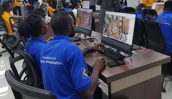
Hexagon’s Safety, Infrastructure & Geospatial division successfully deployed an advanced utility geographic enterprise asset management (EAM) system for the Electricity Company of Ghana (ECG). The smart EAM, featuring Hexagon’s G/Technology, will allow ECG to plan, manage and efficiently operate its distribution network to meet the growing needs of 4.5 million customers.
The enterprise system from Hexagon unifies data from a variety of geographic information systems (GIS), enabling bi-directional data flow with other systems based on the Common Information Model (CIM) standard. The system enhances ECG’s ability to geographically reference and manage assets with integrated tools for data surveying, capture and maintenance and network planning and calculation.
Mobile capabilities enable efficient inspections and maintenance, while a web portal assists employees with locating assets, reviewing the network and more. Migrating to Hexagon’s system will increase process efficiency and reduce asset-management costs by harmonizing systems, validating existing data and capturing missing data.
“The utility GIS is the critical component that fuels innovation in the utility,” said Keli Gadzekpo, board chairman of ECG. “This project is the foundation and the first step to modernizing ECG operations. It is the platform for digitization of electrical network assets, a prerequisite for bringing efficiency in the wire business.”
Photo: Hexagon
Part of ECG’s Modernizing Utility Operations Activity, the project was commissioned by Millennium Development Authority (MiDA), Ghana, on behalf of the Government of Ghana’s Millennium Challenge Account Entity Program and funded by the U.S. government.
“We are exceedingly grateful to Hexagon for working tirelessly to deliver this innovative product,” said Julius K. Kpekpena, Ag CEO and COO, Millennium Development Authority. “The technology sets Ghana’s biggest electric distribution utility on the path to modernizing its operations. The GIS is the foundation for modern tools to help ECG plan its networks, reduce losses, collect revenues and serve customers more efficiently.”
The project included procurement and installation of system software, server hardware, mobile field units and services for data migration by Hexagon, field validation of assets by PDSA Ghana (part of Hexagon), and production of aerial imagery by ILV Wagner using Hexagon’s Leica Geosystems surveying and airborne imaging technologies.
“Reliable electricity requires accurate data and tools to plan, design and manage networks, which can also reduce overall maintenance costs,” said Maximillian Weber, senior vice president, Global Utilities & Communications, Hexagon’s Safety, Infrastructure & Geospatial division. “We are proud to support Electricity Company of Ghana in delivering quality service to its customers.”
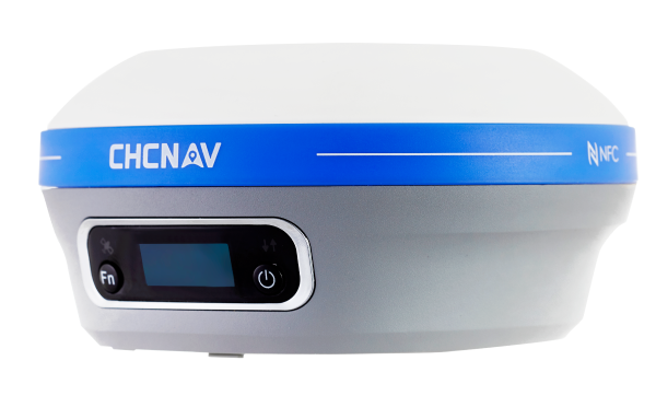
CHC Navigation (CHCNAV) has announced the availability of the i83 GNSS receiver, an addition to its premium GNSS receiver series for surveying, mapping and construction professionals. The i83 GNSS is powered by a 1408-channel multi-band GNSS receiver, the latest iStar technology, and a calibration-free, high-end inertial measurement unit (IMU) for faster and reliable field GNSS surveying.
“The i83 receiver combines GNSS and IMU into one single receiver to provide optimal automatic pole-tilt compensation that requires no calibration and is fully immune to magnetic interference. Operators just need to focus on their tasks and no longer need to level their pole vertically,” said Rachel Wang, product manager of CHC Navigation’s Surveying and Engineering Division. “In addition, we designed a high-resolution color display where users can clearly and intuitively get the GNSS receiver status to take full control of their survey operation.”
The third-generation high-gain antenna with the latest advanced CHCNAV iStar algorithm improves GNSS satellite signal tracking efficiency by more than 30%. The i83 GNSS receiver features 1,408 GNSS channels for high performance across GPS, GLONASS, BeiDou, Galileo and QZSS constellations. Its onboard GNSS technology delivers centimeter-level positioning, maintains reliable fixed real-time kinematic (RTK) accuracy, and collects points faster than previous models, even in demanding conditions.
Automatic compensation for pole tilt
The i83 receiver’s built-in IMU automatically compensates for pole tilt, increasing surveying, engineering and mapping efficiency by 30% over conventional GNSS RTK surveying methods. In less than 5 seconds, the 200-Hz inertial module is initialized to ensure survey-grade accuracy over a pole tilt range of up to 30 degrees. Productivity is dramatically increased, RTK usability greatly improved, and potential human error reduced, whether you are an engineer, site foreman or surveyor.
Integrated Wi-Fi, Bluetooth and near-field communication (NFC) modules provide seamless connection to field data controllers or tablets. Integrated 4G and UHF modems enable any GNSS survey mode, from RTK network NTRIP connections to UHF base-rover configurations. GNSS RTK corrections can be accessed or broadcast continuously for accurate positioning in all circumstances.
Users do not need to carry backup or external batteries in the field because of the i83 GNSS’ ultra-low-power system-on-chip (SoC) electronic design and smart power management. The i83 GNSS can operate for up to 18 hours as a GNSS RTK network rover or more than 8 hours as an RTK base station.
The i83 GNSS receiver is available worldwide through the CHCNAV distribution network.
My February column explained why it is important to account for horizontal movement of marks everywhere, and not just in areas influenced by active crustal movement due to earthquakes such as Southern California.
It provided information about the NOAA CORS Network (NCN) rates of movement based on International Reference Frame of 2014 (ITRF2014) coordinates and horizontal velocity information. It highlighted reports from the National Geodetic Survey (NGS) that describe models that will facilitate users transferring coordinates between reference frames and dealing with intra-frame movement between marks based on surveys performed at different epochs.
NAPGD2022 orthometric heights will primarily be accessed through GNSS technology.
As I stated in my February column, this is not just a horizontal positioning issue. In this month’s column, I address estimates of vertical movement that will have to be accounted for in the new, modernized National Spatial Reference System (NSRS).
NAPGD2022 will provide gridded models for North America (that includes CONUS, Alaska, Hawaii, the Caribbean, Canada, Mexico, Central America and Greenland), American Samoa and Guam/Commonwealth of Northern Mariana Islands (CNMI). My previous columns have described the NAPGD2022 in detail. The revised NOS NGS 64 report mentioned that NAPGD2022 will be built upon ITRF2020. It states that NAPGD2022 will operate equally well in any of the four new terrestrial reference frames developed as part of the new, modernized NSRS in 2022.
As I stated in previous columns, orthometric heights in NAPGD2022 will be defined through GNSS ellipsoid heights and GEOID2022. This means NAPGD2022 orthometric heights will primarily be accessed through GNSS technology. GEOID2022 will be defined in a manner that best fits global mean sea level at the epoch of NAPGD2022.
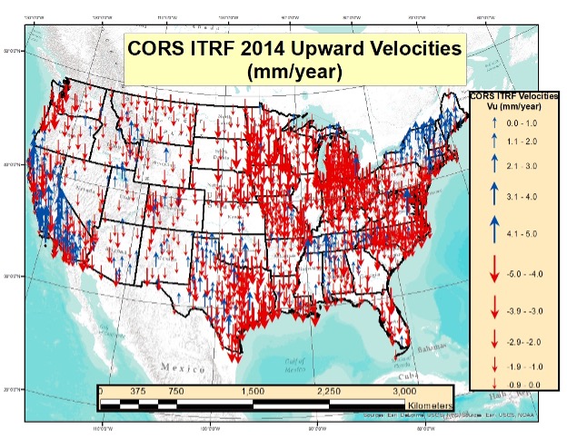
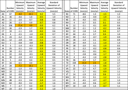
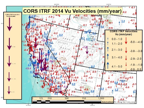
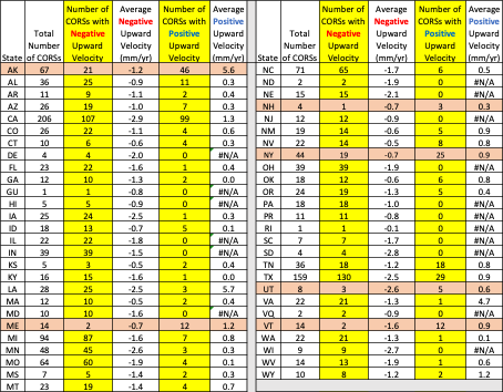
As in my previous column, to better visualize the potential size of the vertical movement, I used the CORS ITRF2014 coordinates and velocities from the NGS website to create plots depicting the upward velocity (Vu) values for CORS that are designated as operational and have computed velocities. [Note: I use the term upward because that is how it is reported on the NGS CORS website under the tab labeled “position and velocity.” The term upward velocity means movement in both directions — negative is downward and positive is upward.] The box below shows maximum, minimum, average and standard deviations of upward velocity values for each state and territory of the United States.
Table of ITRF 2014 Upward Velocities of US CORSs
The upward velocity values are not as systematic as the horizontal velocity values, and they are significantly smaller. I have highlighted the average value velocity column. As indicated in the table, the values vary from state to state, but they are all small relative to the horizontal movement values. (See my previous column for plots depicting the horizontal values.)
What is interesting is the range of values in some states. For example, Alaska and California have a very large range — understandable because of the active earthquakes and other movement that occur in these states. Also, Louisiana and Texas have a very large range due to local subsidence.
I decided to highlight the values for the conterminous United States (CONUS) in two separate plots. The box “Upward Velocities (Vu) Between +/–5 mm/year in CONUS” depicts upward velocities (Vu) between +/–5 mm/year in CONUS. The box “Upward Velocities Greater than Absolute Values of 5 mm/year in CONUS” depicts upward velocity values greater than +/–5 mm/year.
Upward Velocities (Vu) between +/- 5 mm/year in CONUS
Image: Dave Zilkoski
It’s obvious that most of the vertical movement values are between +/–5 mm/year in CONUS. There are some large values in California, Louisiana and Texas. This is highlighted in both plots.
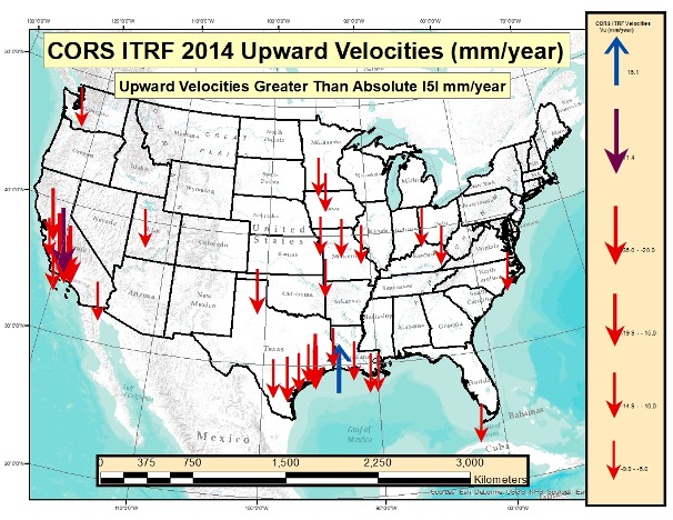
Upward Velocities (Vu) Greater than Absolute Values of 5 mm/year in CONUS
(Image: Dave Zilkoski)
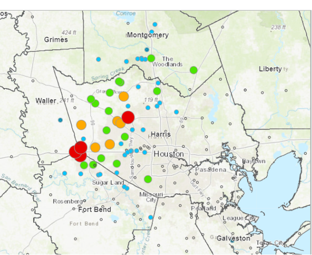
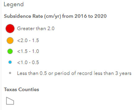
As indicated in the plots, some of the values exceed 10 mm/year. In five years, the heights of marks in these regions could potentially change by 5 cm. An example of the potential subsidence in the Houston-Galveston, Texas, region is depicted in the box below. As indicated in the plot, some marks are subsiding greater than 2 cm/year. That means in five years the marks in that region could have subsided more than 10 centimeters.
Estimate of Subsidence in the Houston-Galveston, Texas, Region
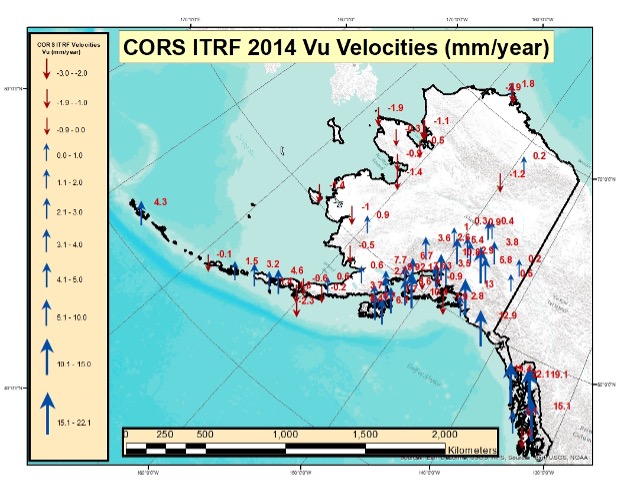
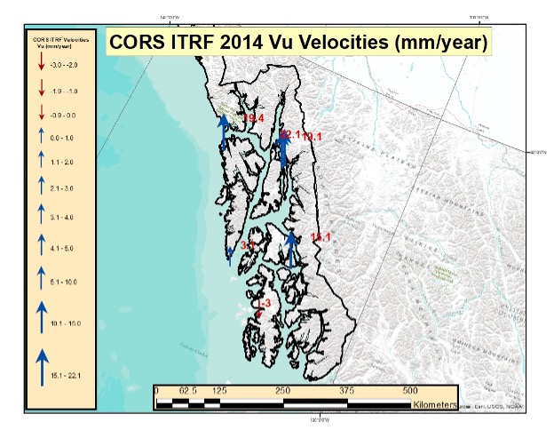
The box below depicts the values in Alaska. Most of these values indicate that the marks are uplifting. Some of these values exceed 10 mm/year. Once again, height coordinates in some regions will potentially change 5 cm in five years. I generated a separate plot for the southeastern region of Alaska. (See the box titled “Upward Velocities (Vu) in Southeastern Alaska.”)
Upward Velocities (Vu) in Alaska [All Values]
Image: Dave Zilkoski
Upward Velocities (Vu) in Southeastern Alaska [All Values]
Image: Dave Zilkoski
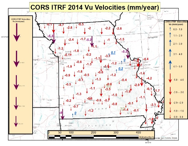
As I did in my previous columns, I prepared several plots that depict the upward velocities in various regions of the United States. See the boxes below for North Carolina, Missouri Southwest U.S. The plots indicate that the magnitude of the vertical movement varies from state to state, as well as within the states.
CORS ITRF 2014 Upward Velocities (Vu) in Missouri [All Values]
Image: Dave Zilkoski
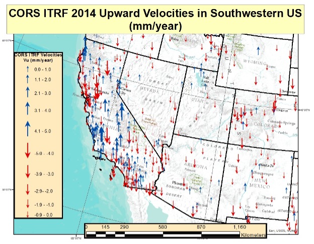
CORS ITRF 2014 Upward Velocities (Vu) in Southwest U.S. [All Values]
Image: Dave Zilkoski
CORS ITRF 2014 Upward Velocities (Vu) in Southwest U.S. [Values Between +/- 5 mm/year]
Image: Dave Zilkoski
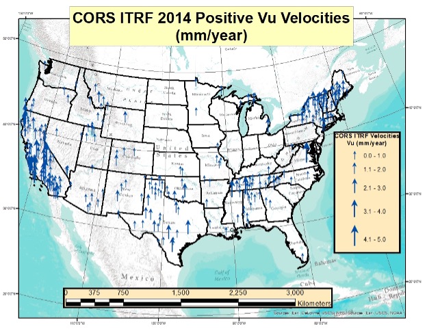
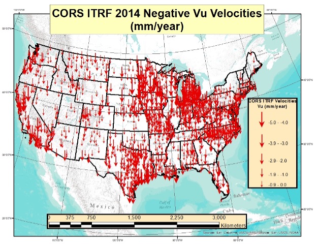
I also generated plots that separately depict the positive and negative upward velocities for the conterminous United States. There are more negative upward velocity values than positive values.
CORS ITRF 14 Positive Upward Velocities (Vu) in Conterminous U.S. (Values between 0 and 5 mm/year)
Image: Dave Zilkoski
CORS ITRF 2014 Negative Upward Velocities (Vu) in Conterminous U.S. (Values between -5 and 0 mm/year)
Image: Dave Zilkoski
The table below provides the number of CORS with negative upward velocity values and the number of CORS with positive values for every state and territory of the United States. I have highlighted the states and territories that have more positive values than negative values. As you can see, only six states have more positive upward velocities than negative values. Four of the six states are in Northeastern United States.
Table of ITRF 2014 Positive and Negative Upward Velocities for United States
So far, this column has only addressed the vertical movement at the NCN CORS. The values at the sites indicate the potential movement of marks in the area of the CORS. The rates are based on GNSS data and have an estimate of error associated with them.
I’m not sure how NGS will address the vertical movement effects in the new, modernized NSRS. That said, NGS will be monitoring the CORS and looking for trends to help describe the movement at the CORS. These trends will be an indication of what may be happening in the area.
In addition to the movement of individual marks, there are geophysical reasons for changes in the geoid. As I stated in previous columns, orthometric heights in NAPGD2022 will be defined through ellipsoid heights and GEOID2022. Therefore, changes in the geoid model will be very important to users estimating orthometric heights using GNSS.
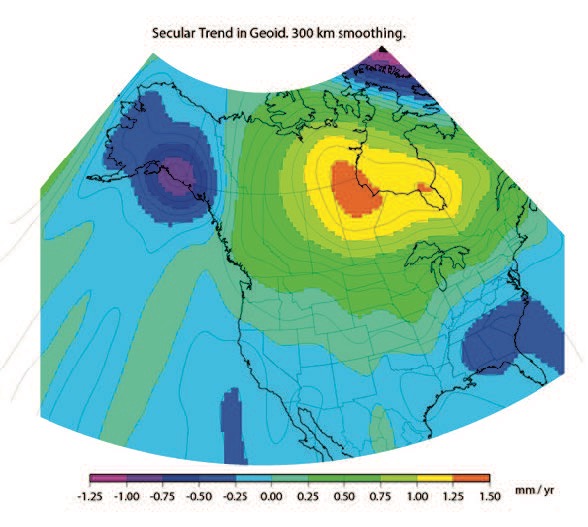
As stated in the NGS 64 report, NGS has set a goal of maintaining geoid accuracy at 1 centimeter (1 standard deviation) in both absolute and differential geoid undulations. Figure 13 from the NGS 62 Report depicts an estimate of the secular change in the geoid. As indicated in the plot, the changes are very small, ranging from –1.25 mm/year to 1.5 mm/year.
What I find interesting is the small negative change in the southeastern United States. There are other drivers for geoid changes. Future columns will address some of these changes and what it means to users.
Figure 13 from NOS NGS 62 Report
Image from NGS website: Blueprint 2 Revised NOAA_TR_NOS_NGS_0064.pdf
Figure 13 – Secular Geoid Change
Lastly, I’d like to highlight a new service from NGS: “NGS Webinar Series Certificates of Attendance.” See the box titled “Ways to Earn a Certificate of Attendance.” Basically, users can earn certificates by viewing a webinar after it has been posted by NGS. This is very useful for users who could not attend the original webinar. I encourage all users to check out the site to find out more information about the new service.
Ways to Earn a Certificate of Attendance
Image from NGS website: https://geodesy.noaa.gov/web/science_edu/webinar_series/certificates.shtml
A module for SurvCE version 6 software enables surveying with mixed brands of GNSS receivers and total stations. SurvCE is a data-collection software package from Carlson Software. SurvPC Hybrid + provides driver support for numerous devices, allowing the surveyor to interface with both types.
Features of SurvPC Hybrid+ include:
Follow Me. An alternative to optical tracking, Follow Me continuously turns the total station towards the prism using the location as determined using GNSS. This eliminates stray reflectors and lengthy searches.
Smart Lock. The software will automatically detect when a user is slowing to take a measurement and lock on the prism so that it’s ready to go.
Smart Staking. With smart staking, it will no longer be necessary to maintain optical tracking during stakeout. Stakeout directions are kept fresh using the GNSS receiver as the surveyor approaches a stakeout point. When close to the point, the total station will automatically turn and lock on the prism for the final staking precision needed.
Cross Check. SurvCE will automatically cross-check the total station and positions determined using GNSS and warn the surveyor when they differ.
Backup Tracking. With backup tracking, SurvCE will automatically show the position determined using GNSS on the map when the total station isn’t locked.
Hybrid-Resection. Easy hybrid-resection allows for setup anywhere using positions determined using GNSS to calculate the total station occupied point and orientation. Measurements from the GPS and total station are time-synchronized for an accurate and simple one-tap resection measurement.
Auto-Localize. Simplify setup by seamlessly auto-localizing the GPS receiver as total-station points are stored.
Easy Setup Wizard. The easy setup wizard walks users through setup using auto-localization, hybrid resection or hybrid localization, then finishes with a cross-check for quick project start.