The Arrow Gold+ and Arrow 100+ plus models build upon the company’s highest demand GNSS receivers
Eos Positioning Systems, the global manufacturer of the Arrow series of GNSS receivers, has released two new Arrow Series GNSS receiver models: the Arrow Gold+ and Arrow 100+.
These plus model receivers expand upon the features of Eos’ two most popular GNSS standard receiver models, the Arrow Gold and Arrow 100.
Arrow Gold+
The Arrow Gold+ (Photo: Eos Positioning)
The Arrow Gold+ includes all the features of the standard Arrow Gold GNSS receiver model. However, the plus model also includes several enhanced features:
A battery life 3.5 hours longer, for a total of 11 hours of field autonomy
Support for additional GNSS signals, including concurrent use of BeiDou B3 and GPS L5 signals when using RTK corrections
Support for the upcoming Galileo E6 High-Accuracy Service (HAS), which will broadcast differential corrections for GPS and Galileo satellites directly from the Galileo satellites
Built-in capabilities of the Eos Bridge to connect with external sensors
The ability to connect multiple mobile devices to a single Arrow GNSS receiver via Bluetooth (sometimes called “multipoint”)
Arrow 100+
The Arrow 100+ (Photo: Eos Positioning)
Arrow 100+ includes all the features of the standard Arrow 100 GNSS receiver model. However, the plus model also includes several enhanced features:
A battery life 6 hours longer, for a total of 18 hours of field autonomy
Support for Atlas H50 (Basic) service subscriptions, which provides 30-50 cm positioning accuracy worldwide when no SBAS or RTK network is available
Built-in capabilities of the Eos Bridge to connect with external sensors
The ability to connect multiple mobile devices to a single Arrow GNSS receiver via Bluetooth (sometimes called “multipoint”)
For a full comparison between standard and plus model Arrow GNSS receivers, view this FAQ article.
An Eos representative can help customers determine whether the new plus models are right for your needs. Authorized Arrow GNSS receiver reseller, contact Eos online.
Topnet Live coverage map for 2021. (Image: Topcon)
Topcon Positioning Group has expanded its Topnet Live GNSS network of correction solutions with more types of correction services and subscription options. According to Topcon, the growth is a result of the increasing demand for digitalization in various industries including construction, surveying, machine control and agriculture.
Flexible service options include Realpoint, the real-time kinematic (RTK) service, and Starpoint, a Precise Point Positioning (PPP) service. The different services have varying delivery methods, coverage and reliable centimeter-level accuracy.
Under a flexible subscription model, customers can purchase to suit their needs. An RTK service supported by precise point positioning (PPP), Skybridge, is available to maintain connectivity and productivity if the customer temporarily leaves RTK coverage.
Topnet Live uses all four GNSS constellations — GPS, GLONASS, Galileo and BeiDou — to provide continuous accuracy and always-on service coverage. The service provides advantages for these industries:
Survey, Construction and Machine Control. Topnet Live removes the need for individual base stations, dramatically increasing flexibility, productivity and safety, and can drive large-scale projects with constant, reliable accuracy.
Precision Agriculture. The solution delivers fast, consistent, accurate positioning at any time day or night for soil preparation, seeding, spreading, spraying and harvesting.
OEMs, System Integrators, Product Designers. The solution provides scalable precise positioning and supports the implementation of flexible business models tailored to fit both OEMs’ and their customers’ needs.
“The Topnet Live RTK network, first established over a decade ago, continues to grow, with 5,100 reference stations globally, a 14% increase in the last year,” said Ian Stilgoe, Topcon vice president. “We are growing throughout the world in areas where there is an increasing demand for productivity and accuracy through digitalization, with strong growth particularly in North America and Europe. We are focused on continued expansion to maximize support for our customers, so they always have the best options globally.”
Original equipment manufacturers (OEMs) supplying automotive, industrial internet of things (IoT), autonomous robotics and all sectors that require positioning, navigation and guidance also benefit from the enhanced robustness of the network, Topcon said. OEMs can sell their hardware with correction services onboard and preconfigured for immediate use by customers, regardless of geographic location, with flexible subscription and licensing options to suit exact needs.
In one of my previous columns, I described the National Geodetic Survey’s (NGS) plans for replacing the North American Vertical Datum of 1988 (NAVD 88) with the North American-Pacific Geopotential Datum of 2022 (NAPGD2022).
As stated in the NOAA Technical Report NOS NGS 64 Blueprint for the Modernized NSRS, Part 2: Geopotential Coordinates and Geopotential Datum, November 2017, recently revised in February 2021, orthometric heights in NAPGD2022 will be defined through ellipsoid heights and GEOID2022. This means NAPGD2022 orthometric heights will primarily be accessed through GNSS technology.
Like NAPGD2022, in the next update of the International Great Lakes Datum, denoted as IGLD (2020), the heights in the Great Lakes Region will be developed from GNSS and a gravity model. Unlike NAPGD2022, where users will be estimating GNSS-derived orthometric heights, IGLD (2020) users will be estimating GNSS-derived dynamic heights using GNSS and a gravity model.
Promote a better understanding of geodesy as a science;
Create a better appreciation of the value of geodetic surveys and thus encourage greater use of such surveys;
Promote geodetic surveys by individuals, government, and private organizations;
Foster the adoption of uniform standards and procedures for completing geodetic surveys;
Promote the processing, publishing, and disseminating of geodetic survey data and information;
Promote programs for testing, calibrating, and evaluating geodetic equipment;
Further the development and implementation of the Global Navigation Satellite System (GNSS) for geodetic, land surveying, and land information system applications;
Inform the membership of new technical developments by meetings of the association and publications in Surveying and Land Information Science (SaLIS);
Promote educational programs in geodesy, geodetic surveying, and related fields;
Cooperate with other similar organizations, both national and international, in support of the science of geodesy;
Encourage the use of geodetic surveys and mathematical coordinate systems in establishing Public Land Survey System (PLSS) corners
As stated above, AAGS cooperates with other similar organizations, both national and international, in support of the science of geodesy. AAGS is a voting member of FIG, which means AAGS has the opportunity to nominate and vote for elected officials, and develop policy that is important to all surveyors and mappers.
The theme of the FIG Working Week 2021 virtual conference was “Smart Surveyors for Land and Water Management: Challenges in a New Reality.” FIG Commission 5 focuses on meeting the highest level of accuracy for positioning and measurement (see box titled FIG Commission 5). Five 90-minute sessions described some of the efforts of FIG Commission 5.
“FIG Commission 5 focuses on meeting the highest level of accuracy for positioning and measurement. It provides the tools, techniques and procedures to educate and train surveying professionals everywhere. Appropriate methodology for data collection and processing are required to be successful in an era of global, integrated geospatial data.”
These sessions raised surveyor awareness of cutting-edge technology, techniques and procedures for using geodetic data and enhanced global cooperation and standardization in conformance with the ideals expressed by the United Nations resolution for a Global Geodetic Reference Frame. There were many good papers on positioning and measurement presented at the virtual meeting. Readers can obtain a list of presentations and papers at this website.
A paper by Jacob Heck, U.S National Geodetic Survey, and Michael Craymer, Canada Geodetic Survey titled “Updating the International Great Lakes Datum: Enabling the Integration of Water and Land Management in the Great Lakes Region” should be of interest to many U.S. and Canadian surveyors. The box below provides a link to the abstract, paper, handouts and video of the presentation.
05.1 – Managing the Land/Water Interface: WGS84 vs. the ITRS
Commission: 4 and 5
Chair: Dr. Mohd Razali Mahmud, FIG Commission 4 Chair, Malaysia
Rapporteur: Dr. Daniel Roman, FIG Commission 5 Chair, United State
Jacob Heck (U.S.) and Michael Craymer (Canada):
Updating the International Great Lakes Datum: Enabling the Integration of Water and Land Management in the Great Lakes Region (11046)
[abstract] [paper] [handouts] [video]
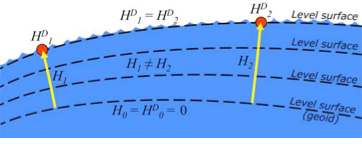
The International Great Lakes Datum uses dynamic heights instead of orthometric heights traditionally used for elevations on land. Figure 4 from Heck and Craymer’s FIG paper, illustrates the difference between orthometric and dynamic heights. See box titled “Figure 4 from FIG Paper by Heck and Craymer.” As described by Heck and Craymer, “The dynamic height represents the difference in potential above the reference surface and is the same at all points on a level surface. Orthometric height represents the actual physical distance above the reference surface which may change due to differences in gravity caused by the convergence of equipotential surfaces toward to the poles. Dynamic heights are therefore required for the proper management of water levels and flows in compliance with international regulations and treaties.”
Figure 4 from FIG paper by Heck and Craymer
Figure 4. Dynamic heights,HD, and orthometric heights, H. (from FIG 2021 paper by Heck and Craymer)
I would like to highlight, as described in the paper and stated in the summary, that access to the future IGLD will be primarily through GNSS techniques.
The International Great Lakes Datum provides a framework for water level management in the world’s foremost resource of surface freshwater. The current datum, IGLD (1985), is being updated and replaced by IGLD (2020). This updated datum will be fundamentally different in terms of definition and access to the datum. The datum will be identical to the new NAPGD2022 North American geopotential datum and will be compatible with the existing CGVD2013 (if not identical as well) at the reference epoch of 2020. IGLD (2020) is expected to be released in 2025 at about the same time as NAPGD2022. Access to both frames will be primarily through GNSS techniques. This will lead to more consistent heights across the entire Great Lakes region. Further information about the IGLD update can be found on the Coordinating Committee website.
This new paradigm is important for anyone who works in the Great Lakes region. Actually, it is important to anyone that surveys in the United States, because this new paradigm will also be used to access the North American-Pacific Geopotential Datum of 2022 (NAPGD2022). Anyone following my columns knows this is the future, and that the National Geodetic Survey (NGS) is leading the way in the United States by modernizing the National Spatial Reference System (NSRS).
Another section that I’d like to highlight is in the box titled “Excerpt from Heck and Craymer Paper on IGLD.”
For IGLD (2020), the geoid height, N, will be provided by GEOID2022 which will be used to define NAPGD2022 and the expected update to CGVD2013. IGLD (2020) dynamic heights will therefore be equivalent to dynamic heights in NAPGD2022 and CGVD2013 at the 2020 reference epoch. For IGLD (2020) heights of water levels, hydraulic correctors may also need to be applied.
An important advancement in the development of the new IGLD and North American datums will be the availability of an accurate crustal velocity model that can propagate ellipsoidal heights between different reference epochs. This will enable heights determined at any epoch to be propagated back to the adopted 2020 reference epoch used for IGLD (2020). This will effectively obviate the need to update the entire IGLD datum for the effects of GIA for a much longer period of time, except for incremental improvements to the velocity model and updates to the reference epoch.
It’s important for users to know that the IGLD (2020) dynamic heights will be equivalent to dynamic heights in NAPGD2022, and an accurate crustal velocity model will be used at any epoch to propagate back to the adopted 2020 reference epoch. The box titled “Determining Heights in IGLD (2020)” is an excerpt from Heck and Craymer’s FIG paper that describes the process that will be implemented for estimating GNSS-derived dynamic heights in the updated IGLD (2020).
In previous realizations of IGLD, spirit leveling was used to determine geopotential numbers which were converted directly to orthometric heights that could then be converted to dynamics heights using equation 4 (𝐻𝐷 =𝐶/𝛾45).
In the geoid-based IGLD (2020), heights will be primarily determined through GNSS techniques which provide a direct measure of ellipsoidal height. Although spirit leveling is more accurate over shorter distances, GNSS methods combined with an accurate geoid model are capable of providing more accurate heights over moderate to longer distances at a small fraction of the cost of leveling.
An orthometric height, H, above the geoid is obtained from a GNSS-derived ellipsoidal height, h, above the reference ellipsoid using the geoid height or undulation, N, of the geoid above the reference ellipsoid. This is represented by the simple equation:
𝐻 = ℎ − 𝑁 (5)
Using equations (2) – (5), the dynamic height can be obtained from the GNSS-derived ellipsoidal height using:
𝐻𝐷 =(𝑔̅ ∗ (ℎ − 𝑁))/𝛾45 (6)
For IGLD (2020), the geoid height, N, will be provided by GEOID2022 which will be used to define NAPGD2022 and the expected update to CGVD2013. IGLD (2020) dynamic heights will therefore be equivalent to dynamic heights in NAPGD2022 and CGVD2013 at the 2020 reference epoch. For IGLD (2020) heights of water levels, hydraulic correctors may also need to be applied.
An important advancement in the development of the new IGLD and North American datums will be the availability of an accurate crustal velocity model that can propagate ellipsoidal heights between different reference epochs. This will enable heights determined at any epoch to be propagated back to the adopted 2020 reference epoch used for IGLD (2020). This will effectively obviate the need to update the entire IGLD datum for the effects of GIA for a much longer period of time, except for incremental improvements to the velocity model and updates to the reference epoch.
As stated by Heck and Craymer, hydraulic correctors may also need to be applied to meet IGLD (2020) International policies, procedures and regulations. Information on IGLD (1985) hydraulic correctors can be found on NGS Geodetic Tool Kit Page.
Another paper presented at FIG Working Week that would be of interest to surveyors is a paper on establishing a geoid-based vertical datum given by Dan Roman, Chief Geodesist at NGS (see the box below). Again, the abstract, paper, handouts and video can be downloaded from the link.
05.1 – Managing the Land/Water Interface: WGS84 vs. the ITRS
Commission: 4 and 5
Chair: Dr. Mohd Razali Mahmud, FIG Commission 4 Chair, Malaysia
Rapporteur: Dr. Daniel Roman, FIG Commission 5 Chair, United State
Roman Daniel (USA): Determining an Optimal Geoid-Based Vertical Datum (10876)
[abstract] [paper] [handouts] [video]
Roman discusses the concept of establishing an International Height Reference System (IHRS) so all countries could provide physical heights across their boundaries and over the oceans (see the boxes titled “Excerpt from FIG Paper by Dan Roman” and “Summary from FIG Paper by Dan Roman “). I’ve highlighted several sections that are important to establishing a IHRS.
The IHRS is relatively recent compared to the ITRS. Ihde et al. (2017) discussed plans for unification of heights globally, which were updated more recently in Sanchez et al (2021). Just as ITRF realizations are made within the ITRS, there will be IHRF realizations made within the IHRS. The key concept here is that positions will first be realized in the ITRS and then expressed in the IHRS. This means that GNSS-accessed geodetic coordinates will determine your position in a realization of the ITRF. Using those ITRF coordinates, geopotential values will be determined from an equivalent IHRF model based above a datum of W0 = 62,636,853.4 m2 s-2. This effectively gives your position in the Earth’s gravity field, which is a physical height. In adopting such a model then, all countries might provide consistent physical heights across their national boundaries and over the oceans.
There is a great deal of activity in modernizing how geospatial data are collected, processed and maintained globally. International agreements are in place to have everyone adopt the Global Geodetic Reference Frame to facilitate geospatial data transfer. The approach will be to realize coordinates in the International Terrestrial Reference Frame and then obtain physical heights from the International Height Reference Frame. Countries may adopt any realization of the ITRF but are restricted to a single geopotential value in the IHRF – W0 = 62,636,853.4 m2 /s2. If comparisons to local tide gauges demonstrate this is not optimum for national definitions of a vertical datum, then an alternate geopotential datum can be determined based on an approach that requires supplemental information.
GNSS-observations on multiple tide gauges will establish local Mean Sea Level and any variations due to Topography of the Sea Surface. A model of the TSS would be required to remove TSS effects at tide gauges to determine the geodetic coordinates of MSL. Use of a geopotential model enhanced by locally obtained gravity data would yield the geopotential number(s) at tide gauge(s). Assuming multiple tide gauges, then an average or some statistical analysis might be made to determine the optimal geopotential value to select as a geoid.
NGS’s new modernized NSRS will be compatible with the concept of an International Height Reference Frame. As stated in Roman’s paper, a recent article by Laura Sanchez, et.al, describes a strategy for the realization of the IHRS (see box below.)
Authors: Laura Sánchez, Jonas Ågren, Jianliang Huang, Yan Ming Wang, Jaakko Mäkinen, Roland Pail, Riccardo Barzaghi, Georgios S. Vergos, Kevin Ahlgren and Qing Liu1
Abstract
In 2015, the International Association of Geodesy defined the International Height Reference System (IHRS) as the conventional gravity field-related global height system. The IHRS is a geopotential reference system co-rotating with the Earth.
Coordinates of points or objects close to or on the Earth’s surface are given by geopotential numbers C(P) referring to an equipotential surface defined by the conventional value W0 = 62,636,853.4 m2 s−2, and geocentric Cartesian coordinates X referring to the International Terrestrial Reference System (ITRS). Current efforts concentrate on an accurate, consistent, and well-defined realisation of the IHRS to provide an international standard for the precise determination of physical coordinates worldwide. Accordingly, this study focuses on the strategy for the realisation of the IHRS; i.e. the establishment of the International Height Reference Frame (IHRF). Four main aspects are considered: (1) methods for the determination of IHRF physical coordinates; (2) standards and conventions needed to ensure consistency between the definition and the realization of the reference system; (3) criteria for the IHRF reference network design and station selection; and (4) operational infrastructure to guarantee a reliable and long-term sustainability of the IHRF. A highlight of this work is the evaluation of different approaches for the determination and accuracy assessment of IHRF coordinates based on the existing resources, namely (1) global gravity models of high resolution, (2) precise regional gravity field modelling, and (3) vertical datum unification of the local height systems into the IHRF. After a detailed discussion of the advantages, current limitations, and possibilities of improvement in the coordinate determination using these options, we define a strategy for the establishment of the IHRF including data requirements, a set of minimum standards/conventions for the determination of potential coordinates, a first IHRF reference network configuration, and a proposal to create a component.
I have highlighted several statements in the box titled “FIG Working Group 5.3.” This working group is focused on issues associated with implementing vertical control based on an International Height Reference Frame (IHRF). NGS is working with these groups to ensure that the United States height system will be compatible with the rest of the world.
I encourage everyone to visit the FIG website and explore the papers given during 2021 FIG Working Week. Here is a list of the FIG Commissions. For more information can be obtained on each commission by clicking on the Commission’s title.
Before the American Congress on Surveying and Mapping (ACSM) disbanded, the four-member organization collaborated to convene annual surveying and mapping conferences in the United States. Topics similar to those presented at FIG Working Week were presented at these conferences. I became a member of ACSM in 1972 and learned a lot from attending and participating in these conferences.
Since these ACSM conferences are no longer being held, I encourage users of geospatial data and GNSS technology to participate in professional societies such as AAGS to enhance their understanding and knowledge of new technical developments in the field of geospatial positioning and measurement. As the current president of AAGS, I am biased, but a benefit of AAGS membership is access to the Surveying and Land Information Science (SaLIS)journal that publishes new technological developments related to geodesy, surveying, and mapping.
GNSS signal convergence means significant time savings for surveyors
Photo: Trimble
Trimble has announced enhancements to its Trimble RTX correction services, tailored to meet the evolving needs of geospatial professionals and part of an ongoing strategy to deliver high-accuracy correction services to users worldwide.
Enhancements are designed to reduce convergence times, provide more reliable and robust signals, and make the workflow for surveyors easier. The enhancements further enable geospatial professionals to untether from the cost and complexities of GNSS base stations and complete fieldwork faster.
Surveyors in many regions worldwide can now spend less time in the field with CenterPoint RTX correction service, converging in typically three minutes compared with up to 15 minutes in the past. The breakthrough convergence-time reduction is available on Trimble GNSS receivers with ProPoint technology and will benefit land surveyors working around the globe by enabling them to start surveying faster.
In addition, CenterPoint RTX now supports the BeiDou III (BDS-III) constellation, which contributes to convergence time improvements. Support for BDS-III and convergence time improvements is available globally via IP/cellular and regionally via satellite delivery. Convergence times for the CenterPoint RTX Fast regions remain unchanged at less than one minute. CenterPoint RTX Fast coverage is available coast-to-coast in the U.S. and Western Europe.
Geospatial professionals will be able to work more reliably in challenging GNSS environments, such as urban multipath or under tree canopy, due to the addition of BDS III and GPS III satellite signals into the Trimble RTX solution. Even as GNSS satellites are retired and new ones become operational, Trimble RTX will consistently track and deliver robust and reliable corrections.
Using a Trimble receiver with ProPoint technology with Trimble Access field software and CenterPoint RTX correction service, surveyors will benefit from a streamlined workflow that simplifies how they work in their local coordinate systems. Surveyors can collect data using CenterPoint RTX correction service without the need for a site calibration or an offset.
“Our teams collaborate to continually improve the Trimble RTX-based real-time correction services integration with our geospatial solutions,” said Ron Bisio, senior vice president of Trimble Geospatial. “Surveyors worldwide rely on Trimble to develop products and services that help them get their work done quicker and easier, and this Trimble RTX update is another example of how we continue to deliver surveyors the tools they need to do their jobs even more efficiently.”
“We are celebrating 10 years of providing Trimble RTX-based correction services and each year our services outperform the year before,” said Lisa Wetherbee, general manager of Trimble Advanced Positioning. “We continue to enhance the performance and overall customer experience to help geospatial professionals increase their productivity and provide them peace of mind that our services and people will be there for them around the clock.”
Trimble RTX subscriptions for Trimble RTX-compatible GNSS receivers are available through Trimble’s Authorized Business Partners or Trimble’s online store.
Earlier this year, we looked back at 2020 and reviewed how surveying has dealt with the worldwide pandemic while adapting to the new tools and technology being created. We discovered the need for surveyors did not diminish during this crisis, and in many places the demand has gone up significantly. Instruments, computers and measuring methods continue to increase in capability and complexity to help with the shortage of qualified field crews, yet we still need to expand our efforts to find the next generation of surveyors.
How do we find those future geospatial experts, data collectors and surveying professionals? The answer is right under our noses, and our current group of practitioners needs to get the word out.
What is the word, you ask?
Technology.
Younger generations understand technology better than most practicing surveyors. New devices, methods and operations are being invented at a fast pace, and our best and brightest should be considering using that technology in a rewarding career. Before we make the big pitch to them, however, we should refresh our understanding of recent surveying history to better understand why technology is a good thing.
How did we get here? A short historical look at measuring
The measurement methods, devices and instruments used by surveyors have radically changed in the past 50 years, and we have covered their evolution in past columns (Survey SceneMay 2016, May 2017 and Sept. 2019).
Instruments and devices used by surveyors vary in their function and output of information. Some are used to physically measure the distance from a stationary point to another, determine horizontal and vertical angles at a specific location, or determine grade differentials between various points. Other instruments are used to determine horizontal or vertical positions to establish locations and elevations. All these instruments are being used to gather positional data on any number of items, but the quality of the information may vary depending on the technology and method used. How?
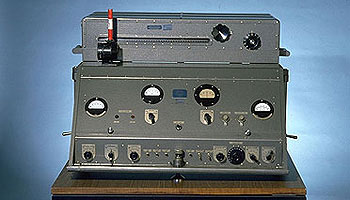
Devices and methods for measuring distances
AGA Geodimeter NASM-2A. (Photo: NOAA)
Tools for measuring distances have been around for centuries. The Egyptians are famous for their “rope stretchers,” while early surveyors in Europe and the New Colonies were known to use the Gunter’s chain and a measuring wheel. In the early 1800s, steel tapes were invented to replace the chain. These measuring tapes continued to evolve well into the 20th century with varying metals, fiberglass and nylon-coated plastics.
In the mid-20th century, scientists and physicists began to experiment using light waves as a means of measuring terrestrial distances. These experiments led to the development of the first electronic distance meter (EDM), commercially produced by the Swedish company Svenska Aktiebolaget Gasaccumulator (AGA) in the early 1950s. Other methods of electronic measurement, including microwave and infrared wave technology, were also developed in the years following the introduction of the lightwave EDM.
For many years, the EDM was used independently from transits or theodolites to measure long distances. For those who needed to consistently measure long distances, the invention of the EDM was not just a time saver, but also provided much higher accuracy than manual measurements.
Other technologies were developed in the latter part of the 20th century, introducing the surveyor to laser scanning, but we can defer this topic until later in this column.
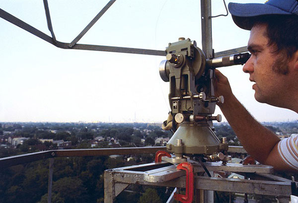
Devices for measuring angles
The T3 theodolite was introduced in 1925. With its 10.5-inch telescope, this theodolite had a range of up to 60 miles. It saw heavy use between 1952 and 1984. (Photo: NOAA)
The surveyor, like the astronomer, has consistently been at the forefront of developing optical instruments. The key has been combining high optical quality with a means of measuring horizontal and vertical angles within the instrument. The creation of the theodolite and the transit revolutionized the ability of the surveyor to accurately measure angles and apply trigonometric functions to determine mathematical computations. In addition, the surveyor’s compass was also developed to assist with angle measurement — with less accuracy but greater flexibility.
By the 1920s, optical theodolite technology was rapidly improving through the work of Switzerland’s Heinrich Wild. Beginning with the T2 and T3, these instruments provided accuracy and precision not previously available to the surveyor. Other manufacturers followed suit with similar instruments for the next several decades and were used in conjunction with the EDM for larger surveys. Anticipation grew with the competition to see which instrument company could marry the theodolite and the EDM into one easy-to-use, yet accurate, optical instrument.
Introducing the total station
By the late 1960s, technology had firmly entered the surveying world with a few electronic advancements. In 1968, Zeiss — a German company known for its lenses and optical systems — produced the first known tachymeter, combining a theodolite with an electronic distance meter. The tachymeter became better known as the total station, as it was capable of measuring angles and distances in one instrument. While somewhat crude and hard to use, the Elta 14 total station introduced the world to a future generation of surveying instruments that would revolutionize the field.
In the course of a few years, several manufacturers developed their own total stations. The biggest hurdle was combining the optics of the scope with the measuring axis of the EDM. By the end of the 1970s, most total stations were coaxial, therefore measuring angles and distances was done with one sighting.
Robotics were introduced in the early 1990s, with two servo motors to drive the horizontal and vertical movements of the total station. These movements were controlled remotely by the tracking system connected to the prism pole and data collector. Not requiring a human being to remain stationary and manually operate the total station provided cost savings and additional efficiency for the field crew.
Positions, everyone! Positions!
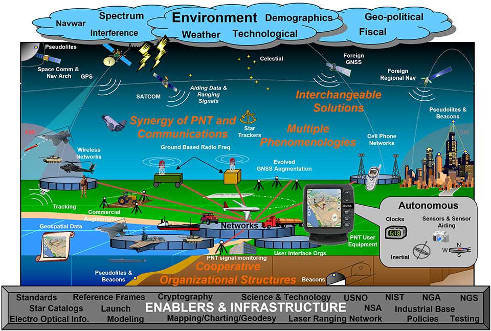
U.S. National PNT Architecture. (Graphic: U.S. Department of Transportation)
Positional measurement has revolutionized not just the surveying profession, but a large portion of everyday tasks as well. From monitoring travel times for your commute to providing your food-delivery driver with your location, position determination is the key element to these services. Satellite navigation is now the primary technology used for positioning, navigation and timing (PNT) and a big part of most aspects of surveying.
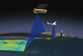
Remote sensing
Here is where we can discuss laser scanning and other remote sensing technologies. Remote sensing is the science and technology of gathering data from a distance. Traditionally this has been mostly done from aircraft, satellites and vessels. However, technology has expanded so that most practitioners now consider the use of laser scanning, lidar, photogrammetry, hyperspectral cameras, bathymetric sonar and simultaneous localization and mapping (SLAM) to be included in the category. Keep in mind that all these technologies are types of measurements; they are not the vehicle or instruments used for the measurement.
Image: NASA
These various sensor types can collect millions of data points in a short amount of time. While surveyors are adapting to working with point clouds and gigabytes/terabytes of data, it is a radical departure from our recent past using only total stations and GNSS receivers. Significant advancements in computer processing, data storage and programming have simplified the manipulation of point clouds, but they remain a challenging task for even newer surveyors to tackle.
Autonomous vehicles
Hobbyists have been building (and crashing) model airplanes and helicopters for many years. Most of the public does not realize that the big advancement in remote-control aircraft was the introduction of GNSS technology into the flight system. Sure, we all have GNSS receivers in our phones, but now to be included in our toys? This somewhat simple addition has turned unmanned aerial vehicles (UAV) into a revolutionary tool for several occupations, not just surveyors. More control and stability of the UAV means expanded uses for emergency personnel, utility providers, parcel delivery and much more. Being able to program a specific flight provides the UAV user with higher accuracy and precision, but it takes away the element of human control.
Image: Department of Transportation
Another vehicle gaining market share is the unmanned surface vessel (USV), used for performing hydrographic surveys. Like its UAV cousin, the USV is autonomous and is programmed to follow a specific route for greater accuracy and precision. Because of the shallow draft of a USV, it can be used in many areas deemed inaccessible by manned vessels.
An additional aspect of newer technology working with autonomous vehicles is collision avoidance systems. These systems have been implemented on newer UAVs and continue to improve, allowing their the use in tighter confines and spaces. By having a radar-based avoidance signal surrounding the entire UAV, collisions become less likely.
Geofencing is another advancement being implemented into more UAVs to help keep them from intruding into unauthorized spaces, by programming into their computer specific geographic areas that are off limits. UAVs are often also programmed to return to its takeoff location under certain circumstances.
Other technological advances to consider
Image: State Department
How much technology do you have in your home and office? Probably more than you realize. While one may immediately think about a smart speaker or home automation system (Alexa, Echo, Nest, etc.), other components offer simple yet productive solutions.
Remote control systems enable you to check whether your doors are locked and your garage door is shut. If not, a touch of a button does the job. Motion sensors enable you to detect intruders around and inside the house, of course. Environmental sensors now monitor for water leaks, moisture and gas/carbon monoxide and provide alerts. How about home automation that utilizes robotic technology? The Roomba vacuum, automatic pool cleaners, and even window washing systems activated when dirt is recognized on your exterior windows are just some of the robotic devices in the modern home.
Precision agriculture utilizes autonomous vehicle control to increase the precision of planting, spraying and harvesting crops. This increase in efficiency has led to higher yields and lower operating costs for the equipment. Another market starting to see more interest is the robotic lawn mowers that functions like the Roomba vacuum. While significantly more expensive than manual mowers, they offer features that can be considered for trade-offs for your time. Depending on your location and needs, they can be set on timers to run day or night and return to base when their battery runs low.
Adapting today’s technology to tomorrow’s surveying tasks
Another relevant technology that does not fit into any of the topics above is the inertial measurement unit (IMU). These sensors are now routinely paired with GNSS receivers in UAVs to help them compensate for pitch and roll. Because of their small form factor, IMUs will increasingly be incorporated into other measurement devices.
It is also safe to say that more handheld devices and smartphones will include lidar scanning capability, as the iPhone 12 Pro and iPad Pro already do. Application and software developers are writing code to make use of data from these devices, so plan on other hardware makers following Apple’s lead.
Voice and motion control will continue to be integrated into data collectors and workstations. By minimizing physical entries into an input system, computers will begin to recognize patterns and automate procedures to increase efficiencies. Programmable voice commands during field data collection will activate various procedures (for instance, specific roadway cross sections or curb island locations) and walk the user through a predetermined set of steps. The possibilities are endless, but we should prepare to take advantage of the technology.
Enticing future generations into a geospatial career
Image: Digital.gov
A geospatial career is so much more than just being a surveyor. Our profession needs bright minds who see the world differently. What does that mean?
Most surveying and mapping tasks used to produce 2D deliverables on paper. Today’s geospatial technicians fly UAVs, use point clouds, draft existing conditions in 3D, and analyze data for future applications. By applying what they are learning with new devices, technologies and software platforms, our younger generations can help the surveying and geospatial profession evolve into a data-rich environment that helps facilitate change for our planet. These efforts can help with climate change, provide better data for our communities, and bring societies back together.
Our profession is much more than gathering data; it is helping to make our world a better place through better data analysis and knowledge. Who would not want that?
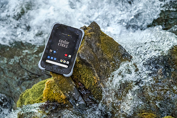
Juniper Systems is has launched its latest rugged tablet, the Cedar CT8X2. The new tablet offers increased processing power, RAM and storage, running on the Android 10 operating system. Despite these features, the CT8X2 retains the same powerful GNSS functionality of the previous Cedar generation for the same price.
“The CT8X2 is our best Cedar tablet to date,” said Cody Draper, Cedar product manager. “It exceeds expectations in terms of price, performance and versatility. It is a perfect device for those looking for a mobile data-collection device that offers a much greater degree of ruggedness than a consumer product.”
Powered by an octa-core Snapdragon CPU from Qualcomm, the CT8X2 allows for larger files compared to the previous Cedar. Greater onboard storage prevents users from needing to offload data frequently and provides sufficient space for applications. With GNSS accuracy of about one meter in open skies and five meters under tree canopy, the CT8X2 offers capable GNSS positioning that far exceeds the accuracy of typical consumer devices. The CT8X2 also has a high-resolution screen.
“The performance increase of the CT8X2 gives users a very capable device in the field,” Draper said. “We were able to provide these advancements in performance and GNSS accuracy while maintaining our affordable price point.”
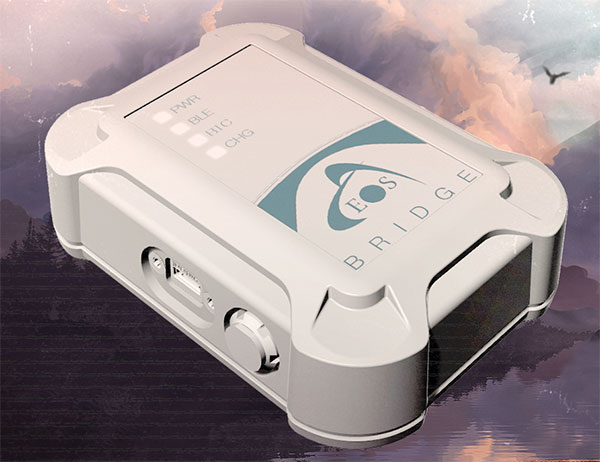
Eos Positioning Systems, the global manufacturer of Arrow Series GNSS receivers, has released Eos Bridge, which enables almost any instrument to become iOS Bluetooth compatible.
Photo: Eos Positioning
The Eos Bridge is a small, pocket-sized device that connects to instruments via Bluetooth Classic or serial port, and transmits data from them to any Apple iOS device, such as iPhone or iPad, Android device or Windows mobile device.
The Eos Bridge offers two connectivity methods to virtually hundreds of instruments:
First Method: Bluetooth Classic to Apple iOS Bluetooth
Instruments that are equipped with non-iOS Bluetooth are now able to connect to Apple iOS devices using the Eos Bridge, including laser rangefinders and utility-locating instruments.
Second Method: Serial port to iOS, Android and Windows devices
With the Eos Bridge, instruments whose only connectivity option is a serial port may now be connected to any iOS, Android or Windows device via Bluetooth. This includes any instrument or sensor with an RS-232 serial port, for example.
The Eos Bridge is lightweight, at approximately 150 grams (about 5.3 ounces). It can be worn clipped to a belt, stored in a pocket, or mounted to an instrument or sensor. The battery lasts 48 to 72 hours.
The Eos Bridge expands the potential pairings of legacy instruments and sensors by making them Bluetooth compatible with modern mobile devices and Arrow GNSS receivers. Two immediate applications for current Arrow GNSS users include Eos Laser Mapping for ArcGIS offset data-collection, and Eos Locate for ArcGIS for underground utility mapping. Both solutions are available on iOS.
Oxford Technical Solutions (OxTS) has launched the latest version of its lidar georeferencing software, OxTS Georeferencer 1.4.
OxTS is taking steps to improve surveyor’s user experience, streamline survey processes, and allow surveyors to get to work faster, while simultaneously improving results.
OxTS Georeferencer fuses position, navigation and timing (PNT) data from an OxTS inertial navigation system (INS) with raw lidar data to output highly accurate 3D point clouds. The software uniquely makes use of navigation diagnostic data that provides surveyors with lidar point-error estimation. This error estimation allows surveyors to focus their analysis on viewing parts of their survey based on estimated errors in points, helping them understand if there are any parts of a survey that need to be looked at again.
Rather than relying on surveyors to integrate their chosen lidar sensors themselves, OxTS has pre-integrated a number of sensors natively. Previous versions of OxTS Georeferencer integrated widely used sensors from Velodyne, Ouster and Hesai. The pre-existing integrations allow surveyors to focus on surveying rather than ensuring the two datasets work in tandem.
Version 1.4 of OxTS Georeferencer integrates new lidar sensors from Hesai. A previous version released in November 2020 was the first integration of the Pandar40P Hesai lidar. Now, seven new Hesai sensors are being integrated:
Pandar40 (beta)
Pandar40M (beta)
Pandar64 (beta)
PandarQT (beta)
Pandar128 (beta)
PandarXT-16 (beta)
PandarXT-32 (tested)
OxTS Georeferencer 1.4 also features several new developments to enhance the user experience and make it more intuitive.
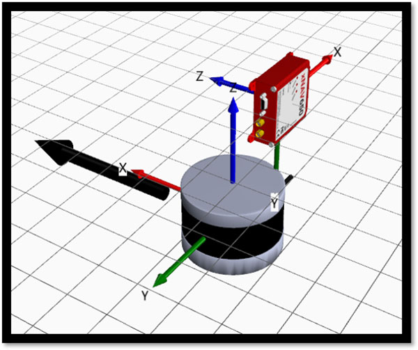
3D Hardware Setup Viewer. To help input the correct relative rotation angles, specific lidar models will be available to view depending on the surveyor’s choice of lidar. The model will represent the lidar sensor in appearance, size and orientation within OxTS Georeferencer with respect to the OxTS INS for quick and intuitive configuration.
The OxTS Georeferencer Hardware setup viewer shows the OxTS xNAV650 INS alongside a Hesai lidar sensor. (Image: OxTS)
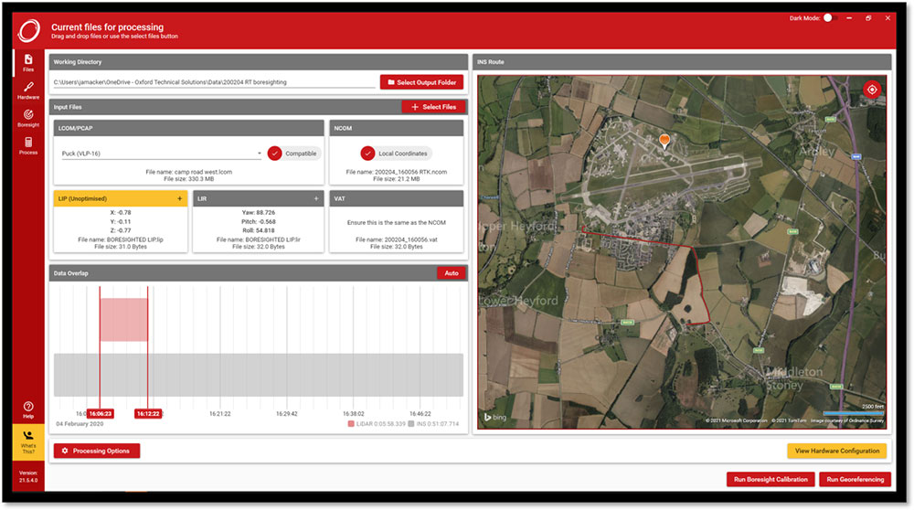
Time overlap chart. Georeferencer 1.4 reintroduces a time overlap chart that allows surveyors to visualize their survey route on a map and select specific start and end times. This enables surveyors to control the part of the route they would like to view, with the added ability to georeference only that section of the survey.
The OxTS Georeferencer time overlap chart. (Image: OxTS)
Lidar CAD models will make it easier for surveyors to calculate and input accurate LIR angles into OxTS Georeferencer, further streamlining the survey process.
The time overlap function will provide surveyors with even more flexibility — this time after the survey. Giving surveyors the ability to choose the start and end times of their survey, and therefore which part of the survey to georeference, enables full control of what to present to their peers.
These new features, coupled with those already present in OxTS Georeferencer (optional boresight calibration and point uncertainty analysis) give surveyors the flexibility and control they need to produce the best possible lidar surveys.
The April column also highlighted one of NGS’ four use cases – “Use Case 1: Flood Mapping.” The case study discusses the Elevation Certificate (CE) Example, Flood Insurance Rate Map (FIRM) and Flood Insurance Study (FIS).
The column highlighted the potential effects of subsidence on published heights in the Houston region, which implied that most of the published heights that are based on older surveys in the region are not current or accurate.
This column will provide more details of the suppression of heights in the Southeast Texas region, and potential effects of crustal movement on published heights in other regions of the United States.
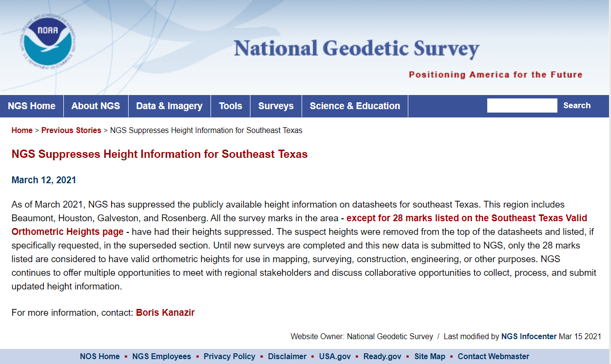
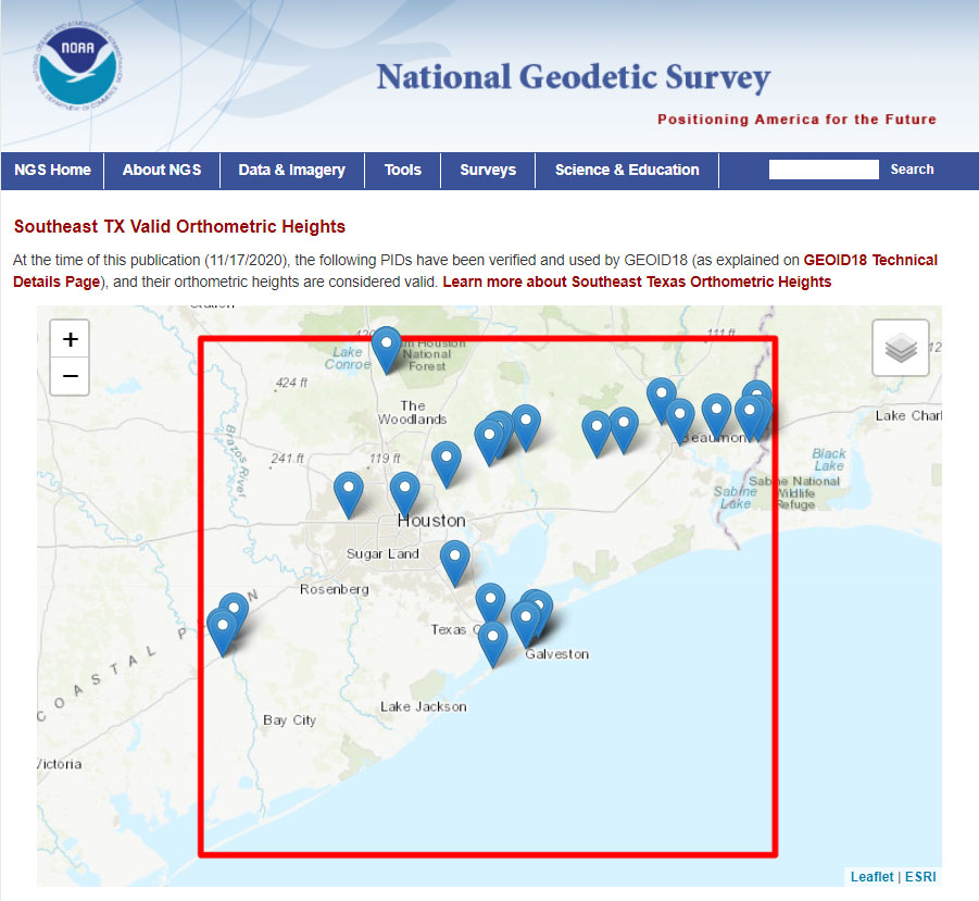
NGS announcement that it suppressed height information for Southeast Texas. (Image: NGS)
According to NGS’ announcement, only 28 marks will have publicly available orthometric heights on NGS datasheets in Southeast Texas.
The “Link to Map: SE TX Valid Ortho. Heights” button provides the benchmarks available to users (see the box titled “Link to Map SE TX Valid Ortho Heights”). The website provides links to the published stations.
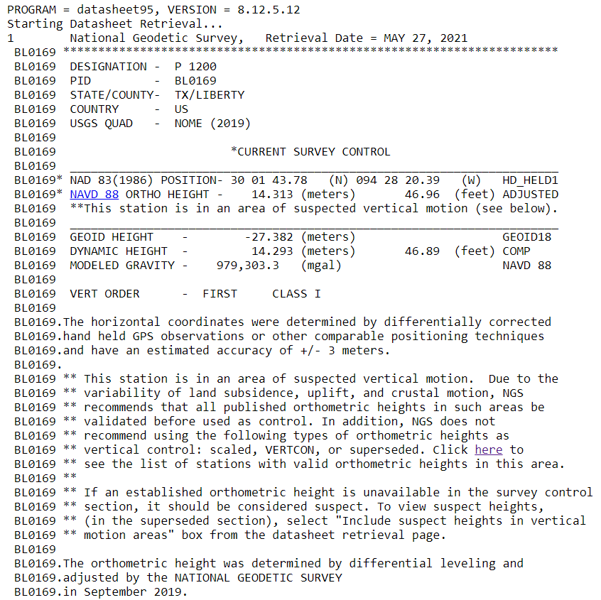
Clicking on an icon provides the PID and name of the station with a link to a datasheet. Click “Get Datasheet” for a datasheet of the station. Below is an excerpt from the datasheet of Station P 1200.
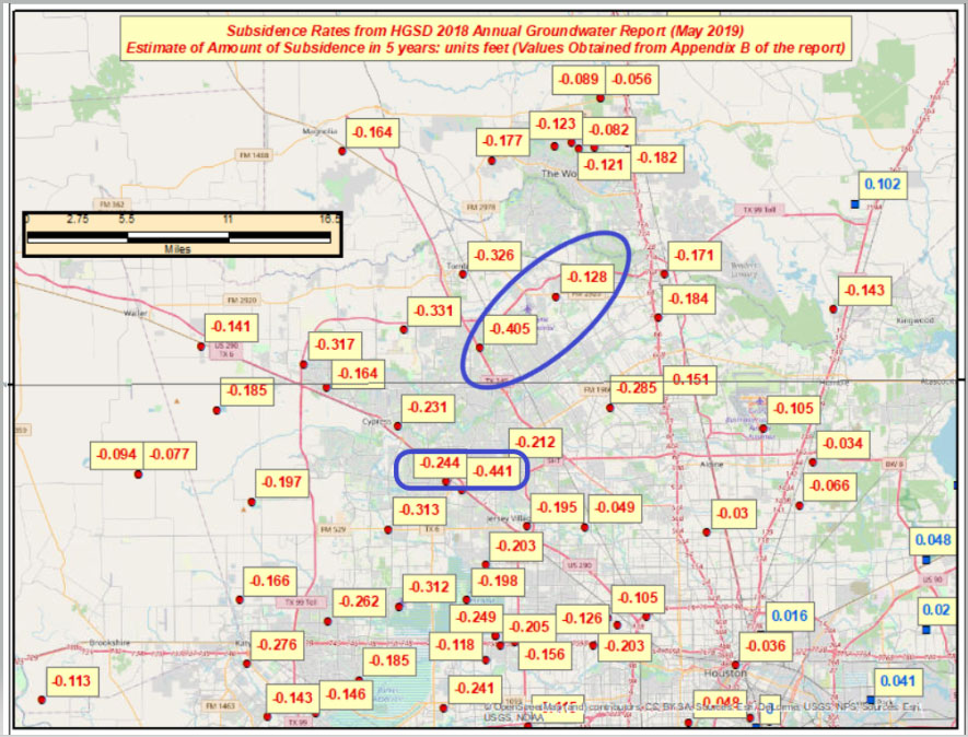
Let’s address why NGS is suppressing the stations in Southeast Texas. My last column provided plots depicting the amount of movement in the Harris-Galveston, Texas, region. See the box titled “Estimate of Amount of Subsidence in 5 Years in Harris-Galveston, Texas, Region – Units Feet.”
As indicated in the plot, some of the marks are estimated to have moved almost ½ foot (approximately 0.15 meters) in 5 years. In addition, some of the relative height differences approach 1/3 of a foot (approximately 0.1 meter) between neighboring stations. See the highlighted stations in the box titled “Estimate of Amount of Subsidence in 5 Years in Harris-Galveston, Texas, Region – Units Feet.”
The last major releveling incorporated into NGS’ Database in the Harris-Galveston, Texas, region was performed more than 30 years ago in the 1986/1987 timeframe. Therefore, some of the published stations in the region could have subsided more than three feet (or about a meter).
As stated in NGS’ Blueprint 3, “Most leveling data in NGS archives comes from the mid-20th century, in support of the NAVD 88 project.” Of course, most regions of the United States are not subsiding at the same rates as in the Houston-Galveston, Texas, region.
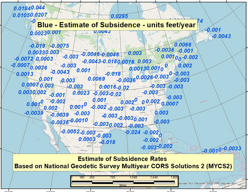
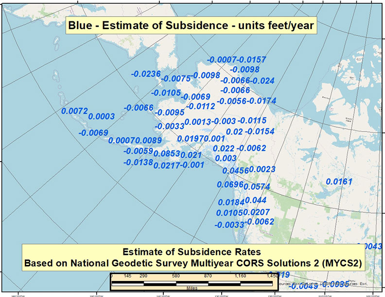
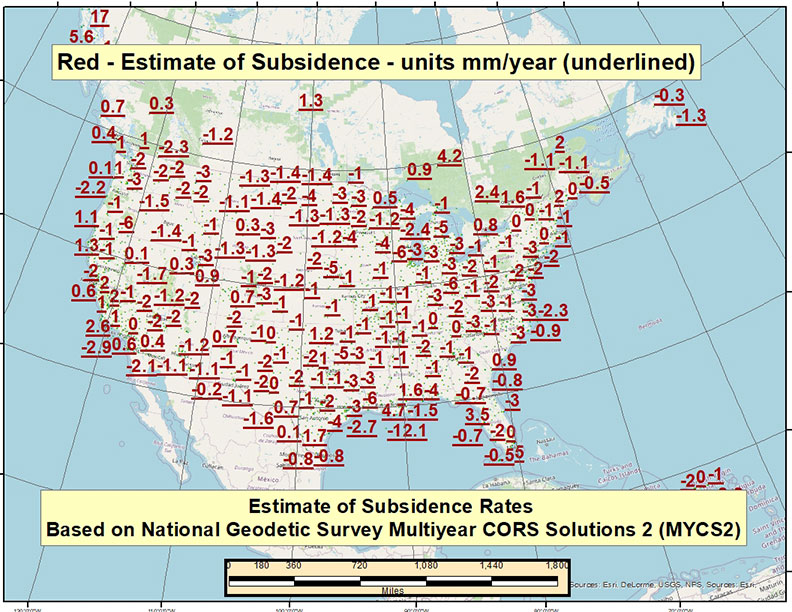
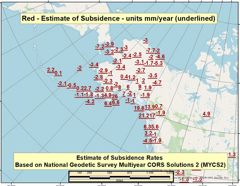
In a previous newsletter, I discussed NGS’ second Multi-Year CORS Solution of the National CORS (MYCS2). I downloaded the coordinates and velocities from NGS’ website and created a plot of the vertical velocities. For those who prefer to use feet as opposed to meters, I provided velocities with units in feet/year and mm/year.
See the boxes titled “Estimate of Velocity Rates Based on MYCS2 – CONUS (feet/year),” “Estimate of Velocity Rates Based on MYCS2 – Alaska (feet/year),” “Estimate of Velocity Rates Based on MYCS2 – CONUS (mm/year)” and “Estimate of Velocity Rates Based on MYCS2 – Alaska (mm/year).”
It should be noted that the intent of these four plots is to provide a wide-ranging view of the values and some of the variation in rates across the United States.
Estimate of Velocity Rates Based on MYCS2 – CONUS (feet/year). (Image: David Zilkoski)Estimate of Velocity Rates Based on MYCS2 – CONUS (feet/year). (Image: David Zilkoski)Estimate of Velocity Rates Based on MYCS2 – CONUS (mm/year). (Image: David Zilkoski)Estimate of Velocity Rates Based on MYCS2 – Alaska (mm/year). (Image: David Zilkoski)
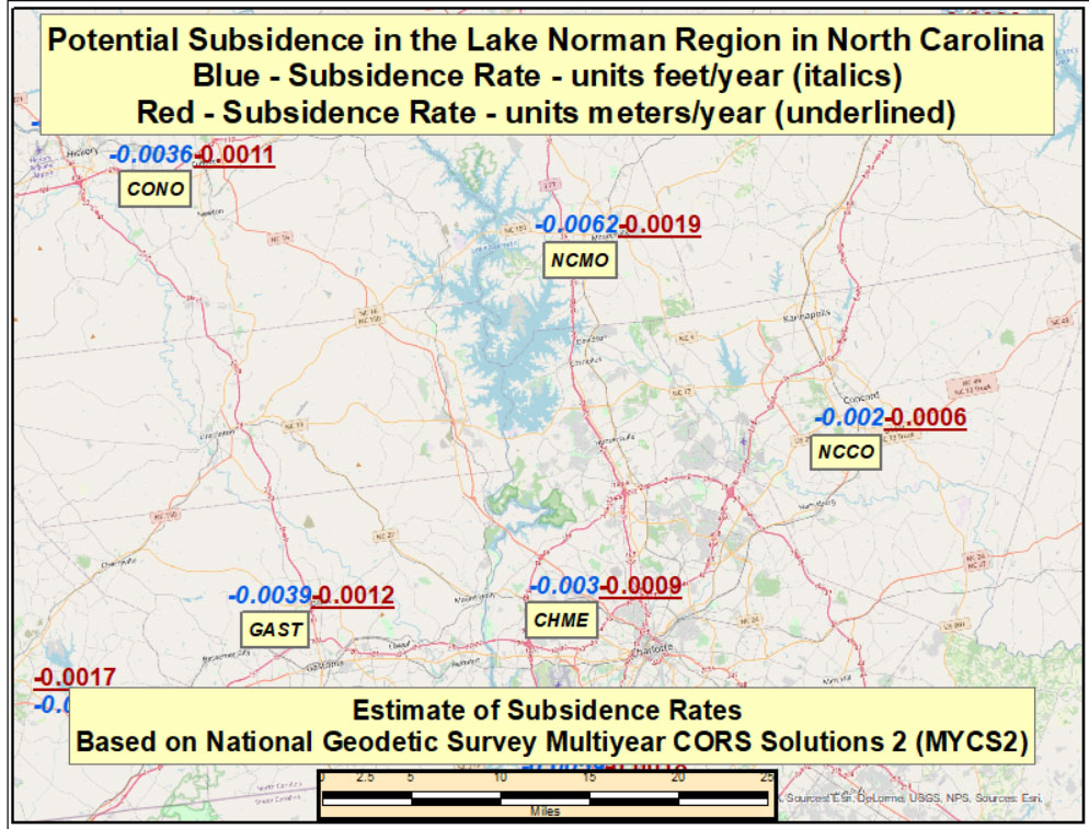
The rates appear to be small in most regions of the United States. As an example, the rates are all less than -0.0062 feet/year (-0.0019 meters/year) in the Lake Norman region in North Carolina (see the box titled “Potential Subsidence Rates in the Lake Norman Region in North Carolina). It would take many years for the crustal movement to make a difference to some projects in this region.
Potential Subsidence Rates in the Lake Norman Region in North Carolina. (Image: David Zilkoski)
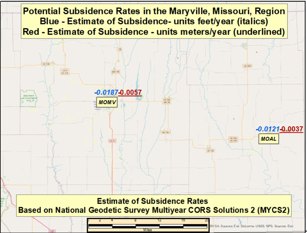
That said, let’s look at another region of the country. For example, in the vicinity of Maryville, Missouri, the rate of subsidence is around -0.0187 feet/year (-0.0057 meters/year). See the box titled “Potential Subsidence Rates in the Maryville, Missouri, Region.” These subsidence rates don’t appear to be large values but if you take into account the last time the height of a mark was established by leveling data it could result in a large difference from the true orthometric height.
Potential Subsidence Rates in the Maryville, Missouri, Region. (Image: David Zilkoski)
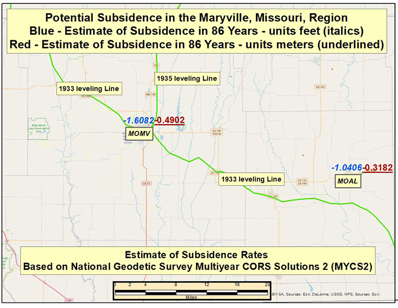
According to NGS’ database, it appears that many of the marks in the Maryville, Missouri, region were last leveled in 1935. I used NGS’ Passive Mark Lookup tool and Leveling Project Page tool to identify the marks and associated leveling lines in the area of the CORS stations in the Maryville, Missouri, region.
I described the Passive Mark Lookup webtool in a previous column. As previously mentioned, these subsidence rates all seem very small, but if you take into account the last time the height of mark was established by leveling data, the subsidence value can be very large.
See the box titled “Potential Subsidence in 86 Years in the Maryville, Missouri, Region.” The box indicates that, if you account for the last 86 years (2021 – 1935), the potential subsidence exceeds 1½ feet (-1.6082 feet, -0.4902 meters).
Potential Subsidence in 86 Years in the Maryville, Missouri, Region. (Image: David Zilkoski)
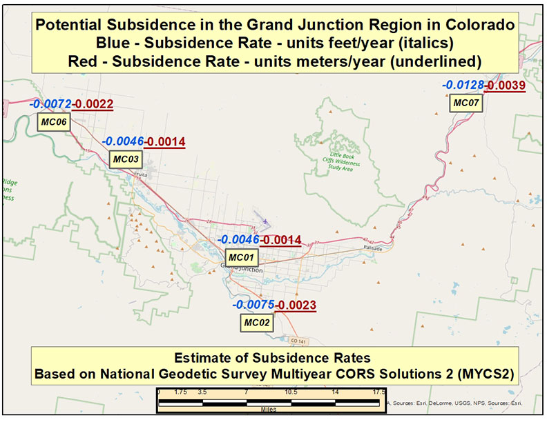
Continuing across the country to Colorado, the box titled “Potential Subsidence Rates in the Grand Junction Region, Colorado,” provides the estimate of subsidence rates in Mesa County, Colorado. As the plot indicates, the rates vary between -0.0046 feet/year (-1.4 mm/year) and -0.0128 feet/year (-3.9 mm/year). Once again, these rates all seem relatively small but many of the marks near CORS MC06 were last leveled in 1985. This means the potential change in height could be as large as 0.2592 feet (0.0792 meters).
Potential Subsidence Rates in the Grand Junction Region, Colorado. (Image: David Zilkoski)
Obviously, this is only an estimate of the subsidence in the region and the actual amount of subsidence is unknown since the last time the mark was leveled. These estimates are based on the MYCS2, which uses current data to estimate the velocity. The processing included data spanning 1996 to 2016 (week 0834 to 1933), 1099 weeks or about 21 years in total.
The point of this column is not to provide the exact change in height of a mark, but to highlight that the publicly available orthometric height on a NGS datasheet may not be up to date based on crustal movement. The new modernized National Spatial Reference System will enable users to determine an accurate, current height on a mark and be able to efficiently and effectively monitor changes in a mark’s height.
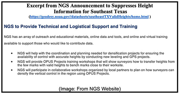
As stated in NGS’ announcement to suppress the heights in Southeast Texas, the agency has developed tools to assist users in submitted data to NGS. See the box titled “Excerpt from NGS Announcement to Suppresses Height Information for Southeast Texas.”
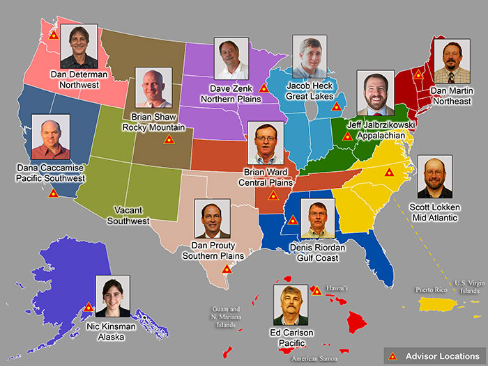
This assistance is for every user, not just for individuals performing surveys in Southeast Texas. NGS has Regional Geodetic Advisors throughout the United States.
The Regional Geodetic Advisors provide guidance and assistance to constituents within their region. They are subject-matter experts in geodesy and regional geodetic issues. These individuals can assist users that are planning GNSS campaigns to re-densify the network.
As mentioned in previous newsletters, a benefit of the new modernized National Spatial Reference System (NSRS) will facilitate the establishment of consistent, accurate NAPGD2022 GNSS-derived orthometric heights.
This column provided details on the suppression of heights in the Southeast Texas region, and potential effects of crustal movement on published heights in other regions of the United States. NGS suppressed the heights in the Southeast Texas region because of the large amount of crustal movement since the last time the heights of the marks were established.
As indicated by NGS’ MYCS2 velocities, every mark could be affected by crustal movement. In my opinion, the question a user should be asking is “How much has the height of the mark changed since it was last determined? Not, “Has the height of the mark changed?”
A roundup of recent products in the GNSS and inertial positioning industry from the June 2021 issue of GPS World magazine.
OEM
Grandmaster Clock
Multi-constellation receiver
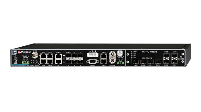
Photo: Microchip
The upgraded TimeProvider 4100 2.2 is now more redundant and resilient. It provides secure, precise timing and synchronization for critical infrastructure such as 5G wireless networks, smart grids, data centers, cable and transportation services. The 4100 2.2 introduces a software-redundancy architecture for flexible deployment, and supports a new GNSS multi-band, multi-constellation receiver to protect against time delay from space weather, solar events and other disruptions. The 4100 2.2 offers options for software and hardware support.
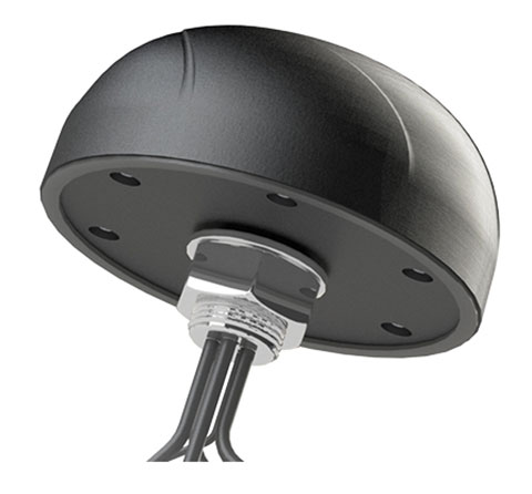
The NETZ 5-in-1 multiple-input and multiple-output (MIMO) solution combines two LTE antennas and two Wi-Fi antennas with a GNSS antenna for high data throughput and streaming, video, industrial and internet of things (IoT) applications. It offers a low-profile design with integrated SubMiniature version A (SMA) connectors and is designed with rugged PC+ABS plastic black housing for demanding environmental challenges.
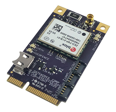
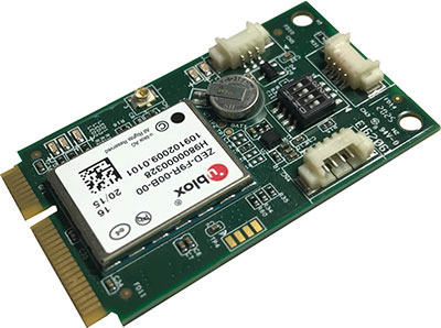
The GW16143 is a high-precision GNSS/GPS Mini-PCLe adapter card that provides precise positioning to applications using Gateworks single-board computers. Based on the U-blox ZED-F9P, the GW16143’s multi-band real-time kinematic (RTK) technology enhances convergence times and performance. The module receives GPS, GLONASS, Galileo and BeiDou; supports L1 and L2/L5 bands; and provides GNSS positioning accuracy
of <2 cm.
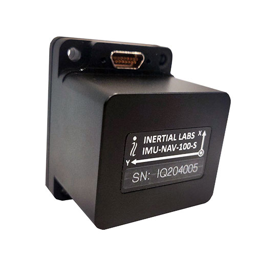
Tactical grade for higher order integrated applications
The IMU-NAV-100. (Photo: Inertial Labs)
The IMU-NAV-100 is a fully integrated inertial solution that measures linear accelerations, angular rates, and pitch and roll with high accuracy utilizing three-axis high-grade micro-electro-mechanical systems (MEMS) accelerometers and three-axis tactical-grade MEMS gyroscopes. It features continuous built-in test, configurable communications protocols, electromagnetic interference protection, and flexible input power requirements that allow it to be easily integrated in a variety of higher order systems. The IMU-NAV-100-S offers high performance stabilization for line-of-sight systems, motion-control sensors, and platform orientation and stabilization systems. The IMU-NAV-100-A is for GPS-aided INS, AHRS and motion reference units.
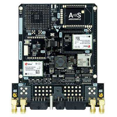
The SimpleRTK2B single-board computer is built around up to three u-blox ZED-F9P high-precision GNSS receivers to simplify development of centimeter-level positioning solutions supporting real-time kinematics (RTK). It was developed to make RTK technology as close to plug-and-play as possible, and make the technology accessible to broader audiences. In addition to working as a stand-alone solution, customers can program their own applications with the company’s microPython API. The SimpleRTK2B-SBC delivers mechanical integration with centimeter position on three axes (heading, pitch, roll), outputting on NMEA, RTCM, RS232 and CANBus interfaces via Ethernet, Bluetooth, Wi-Fi and 2G/3G/4G communication.
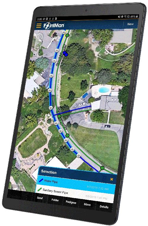
PointMan software is now integrated into the Vivax Metrotech vLoc3 with a GNSS real-time kinematic (RTK) receiver to create a utility-locate device. Using the RTK-Pro internal cellular module with 4G LTE capabilities, the operator can connect to the NTRIP RTK caster that provides RTCM 3 corrections. With the integration of PointMan with the vLoc3 RTK-Pro, critical buried infrastructure can be captured, recorded and displayed at survey-grade without additional external equipment or post-processing. The integration provides centimeter accuracy of the precise location of buried utilities in real time. Data collected includes the type of utility, the depth of cover and the utility’s precise location.
ProStar Holdings, prostarcorp.com
GIS platform
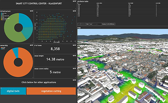
Geospatial and location intelligence for smart cities
Screenshot: Hexagon Geospatial
M.App Enterprise 2021 is a significant update to the platform for creating geospatial and location intelligence applications. The latest release features new browser-based 3D capabilities and enhanced visual effects, plus the ability to create and configure custom applications more easily. It allows users to access LuciadRIA’s 3D features with support for panoramic imagery, shading, ambient occlusion and other visualization effects to build browser-based solutions. It also features a new browser app configurator that makes it easier to create spatio-temporal dashboards, or Smart M.Apps. Feature Analyzer now allows users to add and manage multiple datasets on the fly and set up workflows.
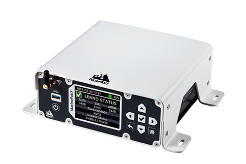
Measures positioning, heading, attitude, velocity and heave
Photo: Hexagon | NovAtel
The MarinePak7 marine-certified GNSS receiver is designed for nearshore applications. The multi-constellation, multi-frequency receiver was engineered to receive the Oceanix Correction Service from NovAtel, providing horizontal accuracy up to 3 cm (95%) in a marine environment. With SPAN GNSS+INS technology capabilities, the MarinePak7 couples GNSS and inertial measurement units (IMUs) for 3D positioning.
The ANNA-F9 high-precision GNSS Mini-PCIe card can achieve centimeter-level accuracy. It integrates the U-blox ZED-F9 receiver platform, providing multi-band GNSS (GPS, GLONASS, BeiDou, Galileo, QZSS and SBAS) and RTK positioning, and can be integrated with embedded systems. It provides high-accuracy positioning for applications including lane-level navigation and railway transportation. The ANNA-F9 series supports RTCM formatted corrections and centimeter-level positioning from local base stations or virtual reference stations in a network RTK setup.
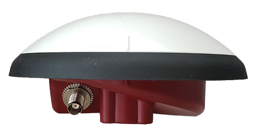
Marine vessels often host both Iridium (1616–1626.5 MHz) and Inmarsat (uplink: 1626.5–1660.5 MHz) satellite communication antennas that transmit and receive signals. The VSP6037L-MAR and VSP6337L-MAR VeroStar marine antennas strongly attenuate interference from both signal sources, providing 75 dB to 85 dB of attenuation over Iridium and 85 dB to 95 dB over Inmarsat uplink, enabling clean GNSS signal reception and precise positioning. The VSP6037L-MAR supports the full GNSS spectrum; the VSP6337L-MAR supports GPS/QZSS-L1/L2/L5, GLONASS-G1/G2/G3, Galileo-E1/E5a/E5b, BeiDou-B1/B2/B2a, and NavIC-L5 signals. Both antennas support L-band correction signals. Every VeroStar antenna features a robust pre-filter and a high-IP3 LNA architecture, minimizing desensing from high-level out-of-band signals, including 700 MHz LTE, while still providing a noise figure of 1.8 dB. They meet IEC 60945 and IEC 61108 marine certifications for challenging marine environments.
The managed internet of things (IoT) Acculink Cargo can track the location and condition of high-value and sensitive assets, providing real-time visibility, product-level tracking and exception-based monitoring as goods move through their supply chains. Tracking can be used to avoid delays, minimize dwell time, prevent theft and remediate environmental conditions that can cause asset damage.
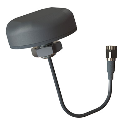
The GNS1559MPF or Mini GNSS is a rugged, high-performance and cost-effective solution for most GNSS or asset-tracking applications. The small form factor makes it easy to install on or in vehicles or buildings. It is IP67 rated to withstand impact as well as water and dust intrusion in demanding environments and operating conditions. The antenna can be configured with different cable types in varying lengths and with various connector types. Uses include public safety, in-building, fleet management, asset tracking, vehicle and personnel tracking.
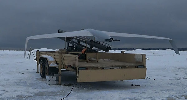
The Zala 421-16E5G long-flight UAS is a domestic unmanned aerial system with a hybrid power plant. The non-aerodrome-based system is capable of providing aerial monitoring covering distances of more than 150 kilometers and staying in the air for more than 12 hours. Its power plant charges a buffer battery for an hour, allowing the UAV to fly long distances. It is equipped with two thermal imagers and a 60x video camera. Alternatively, it can carry a payload of up to 10 kg.
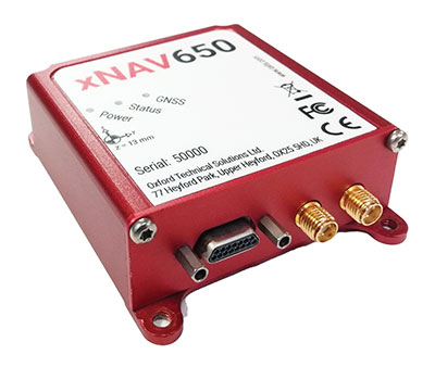
The xNAV650 inertial navigation system (INS) provides surveyors with absolute position, timing and inertial measurements (heading and pitch/roll) that they can integrate into their projects. When combined with data from other devices (such as lidar sensors and cameras), the INS measurements can greatly enhance the surveying process. The xNAV650 has the latest micro-electro-mechanical (MEMS) inertial measurement unit (IMU) technology and survey-grade GNSS receivers. At 77 x 63 x 24 mm and 130 grams, it is suitable for a wide range of UAV data-collection applications: surveys of bridges, buildings, forests and rail; coastal monitoring; map creation; and pipeline exploration. Data collected can be fused with data from almost any lidar sensor. OxTS NAVsuite software is included with all OxTS INS. Other optional software is available, including precision time protocol and GX/IX tight-coupling technology.
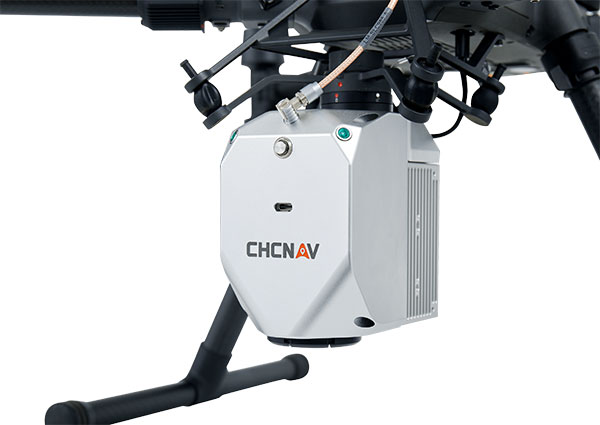
The AlphaAir 450 (AA450) lidar system is a lightweight, compact all-in-one sensor. Featuring an inertial measurement unit (IMU), GNSS receiver and 3D scanner and camera, the AlphaAir 450 is suitable for power-line inspections, topographic mapping, emergency response, agricultural work and forestry surveys. The unit can be rapidly deployed in the field to collect geospatial data. It achieves absolute accuracy of 5 cm (vertical) and 10 cm (horizontal) for small survey areas. Adjustment algorithms applied in CHCNAV CoPre software further improve precision and accuracy. The AA450 weighs 1 kilogram for easy mounting on a UAV. It is IP64 rated against dust and water spray and operates at –20° C to +50° C.
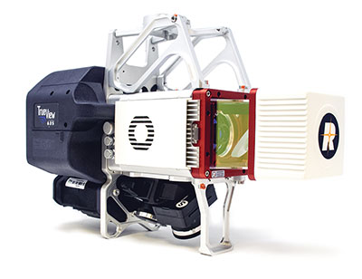
The True View 635/640 3DIS is GeoCue’s second-generation lidar/camera-fusion platform designed to generate high-accuracy 3D colorized lidar point clouds using the Riegl miniVUX-3UAV. All 3DIS platforms include GeoCue’s data-processing software suite True View EVO, which integrates with the Applanix POSPac. With its 120° fused field of view, the True View 635/640 provides 3D mapping with excellent vegetation penetration and wire detection in a payload package of 3.2–3.6 kg. True View EVO supports the direct creation of ground classified point clouds, surface models, contours, digital elevation models, volumetric analysis, wire extraction and similar products, without the need for additional third-party software.
DDK Positioning solutions use the Iridium satellite constellation to deliver 5-cm GNSS accuracy to industrial users of the internet of things (IoT).
Iridium Communications Inc. has made a strategic investment in DDK Positioning, an Aberdeen, Scotland-based provider of enhanced GNSS accuracy solutions.
DDK uses the Iridium network to provide global precision-positioning services that can augment GNSS constellations, including GPS and Galileo, to significantly enhance their accuracy for critical industrial applications.
DDK is developing similar services for other GNSS constellations, such as GLONASS and Beidou. Terms of the investment are not being disclosed.
Standard positioning accuracy through a system like GPS is typically within 10 meters; however, by using the Iridium network, DDK’s enhanced GPS accuracy service brings incredibly precise positioning of 5 cm or less. This advanced level of accuracy is suitable for autonomous vehicles such as UAVs, precision agriculture applications, offshore infrastructure projects such as wind-farm construction, automotive applications like driverless cars, as well as a host of construction, mining, surveying and IoT use cases.
Historically, there have been limited geostationary satellite provider options for this type of service, but they suffer from line-of-sight blockage issues and coverage limitations in and around Arctic and Antarctic regions.
“We are delighted to have embarked on this journey with such a strong and well-respected company as Iridium,” said Kevin Gaffney, CEO of DDK Positioning. “This partnership is a perfect fit for DDK Positioning. With Iridium’s satellite communications network and our GNSS solution, we are in a position to deliver a truly unique service which is robust, resilient and secure. The investment made by Iridium will also allow us to grow the company even further whilst expanding our service offering globally.”
According to a report published by the European GNSS Agency, augmentation services like those offered by DDK will account for $76.5 billion (€65 billion) in global GNSS market revenue by 2029, while the global GNSS downstream market, including services delivered and hardware devices, is estimated to reach $382 billion (€325 billion).
“We are impressed with the team that DDK has put together and see great potential for this technology and how it takes advantage of the Iridium network,” said Iridium CEO Matt Desch. “DDK’s enhanced positioning is a unique capability that adds a high-value solution on top of our existing portfolio of custom network services. Solutions from Iridium and DDK partners that are focused on precision agriculture, autonomous systems, maritime and infrastructure projects can now experience incredibly precise GNSS accuracy from anywhere on the planet.”
As part of an ongoing global correction service strategy, the company is adding more than 400,000 square kilometers (156,000 square miles) to its European footprint, which now totals 2.5 million square kilometers (975,000 square miles).
VRS Now delivers reliable, easily accessible, centimeter-level accuracy that is ideal for professionals in the surveying, GIS and mapping, construction and agriculture industries, as well as many emerging autonomy applications in the automotive and robotics industries.
The subscription service is brand agnostic and works with most GNSS receivers. It is supported by a global team of GNSS network specialists and customer service representatives around the world, ensuring users have a consistent, reliable, high-performing service whenever they need it.
“Launching Trimble VRS Now services to Norway significantly expands our correction services footprint across Europe, offering a robust and reliable accuracy solution to farming, construction and mapping professionals across the region,” said Lisa Wetherbee, general manager of Trimble’s Advanced Positioning Division. “Trimble solutions are helping customers optimize workflows, improve productivity and deliver operational efficiency, while increasing user safety.”