Eos Positioning Systems has introduced a comprehensive RTK NTRIP app for Android that works with its Arrow line of RTK GNSS receivers. An Arrow GNSS receiver combined with the NTRIP app turns an Android smartphone or tablet into a powerful data collector capable of recording 1-centimeter accurate GIS data in real-time.
“We designed Eos Tools Pro for the RTK user,” said Chief Technology Officer Jean-Yves Lauture. “It is, by far, the most comprehensive NTRIP app for Android on the market today, turning smartphones and inexpensive Android tablets into powerful high-precision GNSS data collection devices.“
The app, named Eos Tools Pro, has user-configurable audible and visual alarms to alert the user of high PDOP, lost RTK correction, unacceptable correction age and several other important metrics. It supports all current and future constellations (GPS, GLONASS, Galileo and Beidou).
To eliminate any confusion as to which GPS/GNSS device the user’s app is using, Eos Tools Pro features a dropdown menu so the user may select any receiver the Android device has been paired with.
“The Eos Tools Pro app enables Android devices running Esri’s Collector app on Android smartphones and tablets to collect data as accurate as 1cm when connected to an Arrow GNSS receiver,” said Esri Product Manager Jeff Shaner. “It’s a big leap forward to enable Collector to serve the high-precision GNSS user.”
Google Maps is tightly integrated with the app to display the user’s location anywhere in the world. Detailed satellite information such as a skyplot that plots each visible satellite, whether it’s being used or not, and signal strength bar graphs from each constellation are also displayed. Finally, a Terminal screen displays the NMEA data flowing and allows the user to send commands to the receiver.
Eos Tools Pro and Arrow receivers are targeted at high-accuracy applications like GIS; environmental; agriculture; electric, gas, water utilities; surveying; machine control; and federal, state, and local government.
A new study from U.K.-based Juniper Research has found that annual revenues from commercial drones sales are expected to reach $481 million this year, up 84 percent from last year’s figure of $261 million.
The new research — “Drones: Consumer & Commercial Applications, Regulations & Opportunities 2015-2020” — found that a low price point had significantly reduced the barrier to entry in many sectors, with high-performance models now available for less than $3,000. It claimed that the reduction in drone price points had in turn resulted in their commercial application within an array of new fields including mapping, inspection and monitoring.
Agriculture to Lead Growth. The research argued that strongest growth would occur within the agricultural sector, which Juniper expects to account for 48 percent of all commercial drone sales this year. Here, UAVs (unmanned aerial vehicles) help save time and costs over other methods, such as walking fields on foot and using planes for fly-over filming. Furthermore, the ease of use of a UAV created for the sector allows for more regular crop surveying.
Film and Television. The research also found that demand for UAVs in the film and television sectors is soaring. Drones provide a much cheaper and more flexible alternative to the use of helicopters and other methods to capture footage for the film and TV industry, particularly for action sequences.
Delivery Drone Concerns. The research cautioned that a raft of privacy, safety and security concerns mean that the usage of drones for delivery purposes is likely to be severely constrained or even prohibited within built-up areas.
According to research co-author Windsor Holden, regulators would be extremely wary of allowing planned services such as Amazon Prime Air and Google’s Project Wing to be offered, except as a means of delivering to isolated rural communities.
“Regulators are understandably concerned that the deployment of delivery drones in inner cities would significantly increase the risk of potentially fatal collisions with cars or even pedestrians,” Holden warned.
Terrorist Concerns. The research also claimed that there was a danger that delivery drones could be hacked by terrorists, conceivably delivering an explosives payload into areas where they would be capable of causing high levels of civilian casualties.
According to Juniper Research, the report:
details and segments the various UAVs available in the market.
assesses how drone development will proceed in light of stringent safety and privacy concerns and regulatory hurdles.
analyses key market drivers, technological trends and challenges that currently influence market potential.
determines scenarios that will impact future demand.
provides in-depth forecasts across a range of key metrics.
Also, a new white paper, “Game of Drones,” is available to download from the Juniper website together with further details of the full research and the attendant Interactive Forecast Excel (IFxl).
Genera Energy and PrecisionHawk have partnered to develop new analysis algorithms specific to improving the efficiency and quality of sustainable biomass crop production and distribution.
The algorithms will convert raw aerial imagery collected by UAVs and satellites into an actionable report for biomass crop farmers.
The tools will be publicly licensed for use in the DataMapper software platform.
Within the DataMapper software platform, Genera will license the completed tools in the Algorithm Marketplace, DataMapper’s library of sophisticated algorithms for data analysis.
The store automatically interprets data collected from a drone’s geographic information system during flight.
The Genera algorithms will add to the currently available lineup of algorithms serving the agricultural industry such as assessing plant characteristics, identifying pests, and monitoring disease pressures.
The first group of research tools to be developed under the new partnership will focus on lignocellulosic crops, core to Genera’s expertise.
Four point clouds, nonregistered, of georeferenced images from four UAV flights.
By Christian Eling, Lasse Klingbeil, Markus Wieland, Erik Heinz and Heiner Kuhlmann
Direct georeferencing with onboard sensors is less time-consuming for data processing than indirect georeferencing using ground control points, and can supply real-time navigation capability to a UAV. This is very useful for surveying, precision farming or infrastructure inspection. An onboard system for position and attitude determination of lightweight UAVs weighs 240 grams and produces position accuracies better than 5 centimeters and attitude accuracies better than 1 degree.
Data acquisition from mobile platforms has become established in many applications recently, particularly using unmanned aerial systems (UASs). Unlike other mobile platforms, unmanned aerial vehicles (UAVs) can overfly inaccessible and also dangerous areas. Furthermore, they can get very close to objects to collect high-resolution data with low-resolution sensors, and they enable approach from all viewing directions without physical contact. UAVs now see use in precision farming for phenotyping or plant monitoring, and in infrastructure inspection and surveying.
Data acquisition from mobile platforms has become established in many applications recently, particularly using unmanned aerial systems (UASs). Unlike other mobile platforms, unmanned aerial vehicles (UAVs) can overfly inaccessible and also dangerous areas. Furthermore, they can get very close to objects to collect high-resolution data with low-resolution sensors, and they enable approach from all viewing directions without physical contact. UAVs now see use in precision farming for phenotyping or plant monitoring, and in infrastructure inspection and surveying.
This article addresses lightweight UAV use for mobile mapping and uses the term micro aerial vehicle (MAV) throughout. MAVs can generally be characterized as having a weight limit of 5 kilograms and a size limit of 1.5 meters.
We focus on the development of a real-time capable, direct georeferencing system for MAVs, since spatial and time restrictions often exclude the possibility of deploying ground control points for an indirect georeferencing. The demand for the real-time capability results from the aim to also use the georeferencing for autonomous navigation of the MAV and to enable a precise time synchronization of the onboard sensors. Furthermore, a real-time direct georeferencing also offers the opportunity to process collected mapping data during flight.
Mapping on demand. The goal of this research project, funded by the Deutsche Forschungsgemeinschaft (DFG), is to develop an MAV that can identify and measure inaccessible three-dimensional objects by use of visual information. A major challenge within this project comes with the term “on demand.” This means that apart from the classical mapping part, where 3D information is extracted from aerial images, the MAV is intended to fly fully autonomously on the basis of a high-level user inquiry. During the flight, obstacles must be detected and avoided. To extract semantic information that can be used to refine the trajectory planning, the mapping data has to be processed in real time. When the georeferencing information is used as initial values for the bundle adjustment, the image processing can be significantly accelerated.
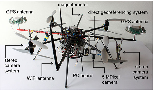
Figure 1 shows the current MAV platform developed in this project. We customized an MAV kit to a coaxial rotor configuration, replaced the centerplates with more stable carbon-fibre plates to stabilize the system, and installed the direct georeferencing and the mapping sensors. The two stereo camera pairs, pointing forward and backward, act as an additional sensory input for the position and attitude determination; the 5M-pixel industrial camera with global shutter is the actual mapping sensor. The PC board is used for onboard image processing, flight planning and machine control; the Wi-Fi module enables a connection to a ground station.
Figure 1. The MAV with mapping and georeferencing sensors, developed for the research project Mapping on Demand.
Although the direct georeferencing system must be small and lightweight, accuracy requirements for its position and attitude determination are high. Generally, these accuracy requirements are different for the machine control, navigation and mapping purposes.
In our project, the MAV is intended to maintain a safety distance of about 0.5 meter to obstacles. Hence, a position accuracy of 0.1 meter is sufficient for the navigation. The absolute attitude accuracy should be in the range of 1 to 5 degrees. For machine control, relative information is more important, and for this the accuracies should be slightly higher.
For mapping purposes, the positions and attitudes have to be known better, since the absolute georeference of the final product (for example, a high-resolution 3D model of a building) is based on the positions and attitudes from the direct georeferencing system. Therefore, the position accuracy should be in the range of 1–3 cm and the attitude accuracy should be better than 1 degree. The relative accuracy of the exterior camera orientation can be improved by a photogrammetric bundle adjustment, but systematic georeferencing errors should be avoided.
To summarize:
The weight of the system has to be less than 500 grams (g), to be applicable on MAVs.
Especially for the control and navigation, the system has to be real-time capable.
All sensors have to be synchronized and outages of single sensors should be bridgeable by other sensors.
The system is intended to provide accurate positions (σpos < 5 cm) and attitudes (σatt < 1 deg) during flights.
The integration of data from additional sensors, such as cameras, should be possible.
The ability to include additional sensors to the system was, apart from the size and the weight constraint, the main reason for developing a proprietary system instead of using a commercial unit with similar capabilities.
Direct Georefencing
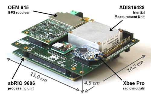
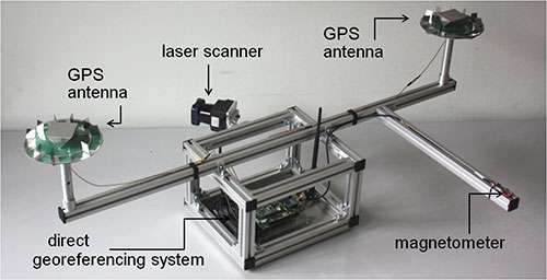
The current version of the system weighs 240 g without GPS antennas (see figure 2). To reduce weight, the antennas were dismantled, reducing their weight from 350 g to 100 g. However, since the antenna reference point got lost in this process, the antennas had to be recalibrated in an anechoic chamber for further use. By comparison to the original antennas, the dismantling led to significant changes in the phase center offsets (circa 4 cm in the Up, < 1 mm in the North and East component) and in the phase center variations (< 5 mm) of the antennas.
Figure 2. The direct georeferencing system.
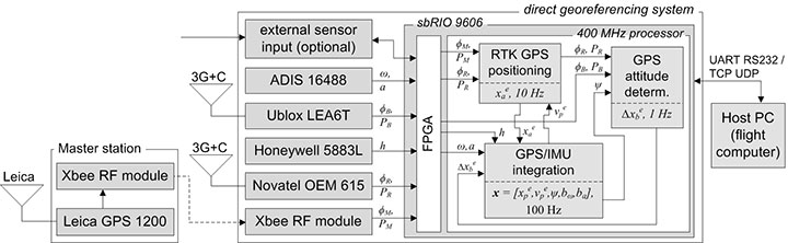
Figure 3 shows a flow chart of the direct georeferencing system with the sensors and the main calculation steps. The system consists of a dual-frequency GPS receiver, a single-frequency GPS receiver, an inertial measurement unit (IMU) and a magnetometer. The dual-frequency receiver is the main positioning device. Together with the GPS raw data from the master station (carrier phases ϕM, pseudoranges PM), which is transmitted via a radio module, the data of the dual-frequency receiver (ϕR, PR) is used for an RTK positioning, leading to centimeter position accuracies.
Figure 3. Flowchart of the direct georeferencing system.
In collaboration with the data of the single-frequency receiver (ϕB, PB), the data of the dual-frequency receiver is also used for GPS attitude determination. The corresponding GPS antennas of these two receivers form a short baseline (baseline length = 92 cm) on the MAV. The determination of the baseline vector in an e-frame (Earth-fixed) enables yaw and the pitch-angle determination.
The tactical-grade micro-electro-mechanical (MEMS) IMU, which includes three-axes gyroscopes, accelerometers and magnetometers, provides angular rates (ω), accelerations (a) and magnetic field observations (h) with high rates (100 Hz) for position and attitude determination. To be unaffected by the electric currents as much as possible, an additional magnetometer is placed on the outer end of one of the rotor-free MAV arms.
The direct georeferencing system further consists of a processing unit, which is a reconfigurable IO board, including a field programmable gate array (FPGA) and a 400-MHz processor. In this combination, the FPGA is used for fast parallel communication with the sensors. Afterwards, the preprocessed sensor data are provided to the 400-MHz processor via direct memory accesses, avoiding delays and supporting the system’s real-time capabilities. Finally, the actual position and attitude determination is carried out on the 400-MHz processor.
Methodologies
All position and attitude determination algorithms running on the system were developed in-house. Generally, the integration of these steps could be realized in one tightly coupled approach. Nevertheless, in the current implementation, we decided to separate the different raw data calculation steps, and we only use interactions at the level of parameters. This approach has the advantage that the integration is more reliable and more practical in the real-time programming.
GPS/IMU integration. In this calculation step, all available sensory input is fused to determine the best position and attitude of the system that is currently available. The GPS and the IMU measurements complement each other well, since the IMU provides short-term stable high-rate (100 Hz) data, and the GPS provides long-term stable low-rate (10 Hz) data.
The GPS/IMU integration can be separated into the strapdown algorithm (SDA) and the Kalman filter update. In the SDA, the high-dynamic movement of the system is determined integrating the angular rates and the accelerations of the MEMS IMU in real time. Because the SDA drifts over time, the long-term stable measurements of the magnetometer and the GPS receivers are needed to correct and bound the drift of the inertial sensor integration, which is realized in an error state Kalman filter.
In the GPS/IMU integration algorithms, the navigation equations of the body frame (b-frame) are expressed in an e-frame. Therefore, the full state vector x includes the position xep and the velocity vep, represented in the e-frame. For the attitude representation a quaternion q is used. Finally, the accelerometer bias bba and the gyro bias bbω are also estimated:
The observations in the measurement model are:
the RTK GPS position xea of the dual-frequency RTK GPS antenna reference point, expressed in the e-frame,
the GPS attitude baseline vector Δxeb, expressed in the e-frame,
the magnetic field vector hb, expressed in the b-frame.
Because the reference point of the RTK GPS antenna is not identical to the system reference point, a lever arm between the system and the antenna reference point must be regarded in the measurement model of the RTK GPS positions. From calibration measurements, the coordinates of the lever arm are precisely known in the b-frame.
In the SDA, a coupling between the accelerations, measured by the IMU, and the positions, measured by the RTK GPS, exists. Due to this coupling the yaw angle can be observed, but only in the presence of horizontal accelerations.
To determine an accurate and reliable yaw angle for every motion behavior, the short GPS baseline is realized on the MAV. A significant challenge in processing this baseline is the ambiguity resolution, because only single-frequency GPS observations can be used. Empirical tests have shown that the ambiguity resolution of a single-frequency GPS baseline generally takes several minutes. Among other strategies, we use the additional information from a magnetometer to improve the ambiguity resolution and to actually enable an instantaneous ambiguity fixing during kinematic applications.
Ferromagnetic material on the UAV and high electric currents of the rotors create significant disturbances of the magnetometer during flight. While the influence of the material can be compensated by calibration procedures, the influence of the dynamically changing electric currents are more challenging. To minimize them, the magnetometer is placed at the outer end of a rotor-free arm of the MAV. Also, the measurement model is arranged so that magnetic field observations only have an impact on the yaw determination in our algorithms.
RTK GPS Positioning. RTK GPS positions are calculated in real time with a rate of 10 Hz. These RTK algorithms are in-house developed, although commercial and open-source solutions are available. The main reasons for developing custom software are the following:
Integration of other sensors and/or solutions is possible, to improve ambiguity resolution and cycle-slip detection.
In commercial software, there is generally no access to the source code.
In the development of a real-time capable system, the software must meet the requirements of the operating system running on the real-time processing unit.
Generally, the RTK GPS algorithm complies with a single baseline determination (one master, one rover), where the master station remains ground-stationary and the rover is onboard the MAV.
To resolve the ambiguities and finally to determine the RTK GPS positions, the parameter estimation is performed in three steps: float solution, integer ambiguity estimation and fixed solution.
The float solution is realized in an extended Kalman filter (EKF). Beside the rover position, represented in the e-frame, the EKF state vector xSD also contains single-difference (SD) ambiguities N j on the GPS L1 and the GPS L2 frequencies. The reason for estimating SD instead of double-difference (DD) ambiguities is to avoid the hand-over problem that would arise for DD ambiguities, when the reference satellite changes.
To allow for an instantaneous ambiguity resolution, the observation vector l consists of DD carrier phases Φjkrm and DD pseudoranges Pjkrm on the GPS L1 and the GPS L2 frequencies.
In the current implementation, a random walk model is assumed as a dynamic model of the MAV in the EKF. Even if this is a simple model, it complies with the movement of the vehicle, when the process noise is chosen appropriately.
The float solution procedure provides real-valued ambiguities and their covariance matrix. These ambiguities now must be fixed to correct integer values, to fully exploit the high accuracy of the carrier phase observables. We applied the MLAMBDA method for integer ambiguity estimation.
Finally, a decision must be made whether or not the result of the integer ambiguity estimation can be accepted. This is done by the simple ratio test. With the ambiguities fixed, the final rover position xae is estimated with cm accuracies.
Usually, the time to fix the ambiguities with the algorithm takes a few epochs, but often the ambiguities can be fixed instantaneously. Once ambiguity resolution has been successful, the ambiguities can be held fixed, as long as no cycle slip or loss of lock of GPS signals occur.
Due to the GPS/IMU integration, we have a precise prediction of the RTK GPS positions between two epochs. Thus, the integration of the inertial sensor readings enables us to detect and also repair cycle slips very reliably.
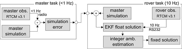
The observations of the master receiver must be transmitted via radio to the direct georeferencing system. In practice, this data transmission can only be realized with a rate of 1 Hz. To be less dependent on this potentially unreliable master data transmission and the lower sampling rate, simulated master observations are used for RTK GPS position determination. Hence, in the actual processing, the true master observations are only used to update the simulation errors in the master task (figure 4), which have to be applied to correct the simulation results in the rover task.
Figure 4. Task scheduling of the RTK GPS algorithms.
GPS attitude determination. The GPS baseline is determined at 1 Hz. In contrast to the RTK GPS positioning, both antennas of the attitude baseline are mounted on the MAV, so that the complete baseline is moving. Furthermore, the baseline length is constant and known from calibration measurements. The GPS attitude determination also consists of the three steps: float solution, integer ambiguity estimation and fixed solution.
The float solution is also based on an EKF where the single-frequency SD ambiguities N j of the attitude baseline are estimated. Further parameters in the state vector are the baseline parameters and the first deviation of the baseline parameters.
As observations DD carrier phases ΦjkAB and DD pseudoranges PjkAB on the GPS L1 frequency are used. To improve the ambiguity resolution, the attitude from the GPS/IMU integration is added to the observation vector, by transforming the known b-frame baseline parameters into the e-frame. Finally, also the known baseline length can be added as a constraint to the observation vector.
In the integer ambiguity estimation, we apply the MLAMBDA method again. Due to the prior information about the attitude of the baseline, the float ambiguities can already be estimated with high accuracies in the float solution. If the ambiguities could not be fixed with the MLAMBDA method, we consider the 10 best solutions for further processing. Unreliable ambiguity parameters are eliminated in a random order, and the MLAMBDA method is applied again. Afterwards we use the ambiguity function method and the known baseline length to exclude false candidates of the 10 best solutions.
If only one solution remains, the ambiguities can be fixed to integer values. Tests have shown that this approach leads to an instantaneous ambiguity resolution success rate of about 95 percent.
Similar to the RTK GPS positioning, the IMU readings are also used to detect cycle slips for the attitude baseline determination, when the ambiguities have been fixed successfully. With ambiguities fixed, the baseline parameters can be determined with millimeter to centimeter accuracies. This leads to yaw angle accuracies in the range of 0.2–0.5 degrees, when the attitude baseline has a length of 92 cm.
Applications and Results
As mentioned, one goal of Mapping on Demand is 3D reconstruction from visual information. The opening image shows such results. During four flights. images were collected with a sampling rate of 1 Hz, and the position and the attitude of the camera was determined in real time using the direct georeferencing system. A bundle adjustment was processed using these positions and attitudes as initial values. Afterwards, dense point clouds could be generated from the oriented images using an open-source software package (PMVS). Due to georeferencing of the collected images, the point clouds are also georeferenced. The image shows results of four flights in one scene, to demonstrate consistency of the georeferencing.
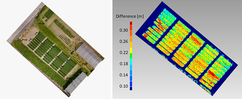
Agriculture. In figure 5, georeferenced images were taken during a flight over a wheat field. The same process was repeated after two weeks. The difference of the respective point clouds, which were determined using the software Photoscan by the company Agisoft, reveals the plant growth at an interval of two weeks. These results show that the determination of plant growth rates, which usually result from time-consuming field work, can be done easily and with high resolution using MAVs. With the use of a direct georeferencing system, this process becomes even more efficient because the deployment of ground control points can be omitted.
Figure 5. Orthophoto of a wheat field (left) and the difference of the vegetation height, determined from the results of two MAV flights at an interval of two weeks (right).
Portable laser scanning system. The small and lightweight design of the direct georeferencing system offers several other opportunities for various applications. One example is the use of the direct georeferencing system in combination with a small, lightweight and low-cost laser scanner.
Terrestrial laser scanning has become an established technology for 3D data acquisition in surveying and mapping because laser scanners provide high-resolution data with high accuracies at high speed. However, for measurement of a complex scene, the laser scanner generally has to be moved to different viewpoints, and all measured scenes have to be registered and georeferenced, a significant increased effort. In contrast, with a directly georeferenced kinematic laser scanning system, complex scenes can be measured with little effort.
Figure 6 shows a portable laser scanning system we developed for kinematic laser scanning. It combines the direct georeferencing system with a low-cost, lightweight 2D time-of-flight laser scanner. Time synchronization and the point cloud calculation are directly realized on this unit.
Figure 6. A directly georeferenced portable laser scanning system for kinematic 3D mapping.
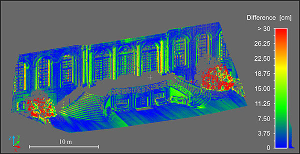
Figure 7 shows differences between a directly georeferenced point cloud, measured by the portable laser scanning system, and a terrestrial laser scanning point cloud, which was indirectly georeferenced using ground control points. Although there are some systematic errors visible, the differences are mostly less than 7.5 cm. The larger differences in the foreground (red) are a result of growing vegetation in the period between both scans. The systematic errors result from the system calibration between the laser scanner and the direct georeferencing system. We are working to improve these calibration methods.
Figure 7. Difference between the results of the directly georeferenced portable laser scanning system and the results of a terrestrial laser scan, which act as reference solution here.
Manufacturers
The MAV is based on a MikroKopter OktoXL assembly kit of HiSystems GmbH. It uses NavXperience 3G+C GPS antennas. The system consists of a dual-frequency NovAtel OEM 615 GPS receiver, a single-frequency u-blox LEA6T receiver, an Analog Devices ADIS 16488 IMU, a Honeywell HMC5883L magnetometer, an XBee Pro 868 radio module, a National Instruments sbRIO 9606 processing unit and a Hokuyo UTM30LXEW 2D time-of-flight laser scanner.
Christian Eling holds an MSc degree in geodesy and is a scientific assistant at the Institute of Geodesy and Geoinformation (IGG) of the University of Bonn.
Lasse Klingbeil received his Ph.D. in experimental physics in 2006. He heads the GNSS and mobile multi-sensor systems group in the IGG. Markus Wieland is a graduade mechanical engineer responsible for the mechanical and electrical design and for the control and readout of various sensor systems at the IGG.
Erik Heinz received his MSc in geodesy and geoinformation from the University of Bonn. He is a Ph.D. student at the IGG. Heiner Kuhlman is a full professor at the IGG. He has worked extensively in engineering surveying, measurement techniques and calibration of geodetic instruments.
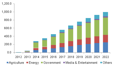
The global commercial UAV market is expected to reach $2.07 billion by 2022, according to a new study by Grand View Research Inc.
Increasing applications in agriculture and law enforcement are expected to drive commercial UAV industry growth over the forecast period. Commercial drones are finding applications across various industry verticals globally. Every industrialized country in the world is making investments in drones, thus driving the scope and technological developments for applications in the commercial UAV market.
Drones are contemporary alternatives for activities where human life cannot be risked. Such drones find applications in various industrial verticals including military, homeland security, retail and agriculture. The demand is significantly higher for military applications, although commercial applications are progressively catching up.
Aviation regulatory bodies such as the Federal Aviation Administration (FAA) have imposed restrictions on the use of such drones taking into consideration the difficulties in managing such huge air traffic and the safety of the citizens. However, the FAA is known to be undertaking an initiative to accelerate the UAV approval process for public safety agencies and broaden access to civilian organizations for a variety of commercial, industrial and other applications.
Further key findings from the report suggest:
Rotary blade drones accounted for more than 70 percent of the global market share owing to their easy maneuverability and compact design. Moreover, such single and multi-rotor drones equipped with rotary blades have Vertical Take-Off and Landing (VTOL) abilities for applications, where there is limitation of space for fixed blade drones to take off. The development of advanced hybrid UAVs that operate on non-conventional sources of energy and nano, small miniature drones serve multiple applications across various industry verticals.
Government applications dominated the global commercial UAV industry constituting more than 40 percent of the market share in 2014. Increasing applications in law enforcement, security and surveillance, R&D activities, infrastructure, disaster management, and environmental studies have led to an increased demand for such unmanned aerial vehicles from the concerned government agencies. Innovative applications across agricultural sector have made it the fastest growing application segment, which is projected to grow at a CAGR of more than 18 percent from 2015 to 2022. Special agricultural drones can take snapshots of fields and help in analyzing crops. In addition, fix winged drones can be used for applications such as watering, spreading seeds, fertilizers, and pesticides over large farm fields that drastically reduce the time required and increase the efficiency.
North America is expected to grow at a CAGR of more than 16 percent over the forecast period on account of concentration of major drone manufacturers and increasing applications in the commercial sectors in the region. Governments and technology giants across the world are striving hard to provide internet to the people as a basic necessity. Facebook Inc. recently acquired Ascenta, a drone manufacturer for its pilot project to provide internet in remote areas using drones as movable wireless access points. Relaxation in regulations and increasing use of drones in law enforcement activities in Europe have led to the regional industry growth.
Major industry participants include AeroVironment Inc., BAE Systems, DJI, Elbit Systems, Parrot SA, Israel Aerospace Industries, The Boeing Company, and Textron Inc. Manufacturers resort to mergers and acquisitions as their key growth strategy to make their presence felt in the industry. Augmented funding, technological collaborations, and government agencies are expected to emerge as critical success factors for industry growth.
Grand View Research has segmented the global commercial UAV market on the basis of product, application, and region:
Commercial UAV Product Outlook (revenue, USD billion, 2012-2022)
Fixed wing
Rotary blade
Nano
Hybrid
Commercial UAV Application Outlook (revenue, USD billion, 2012-2022)
Agriculture
Energy
Government
Media & Entertainment
Others
Commercial UAV Regional Outlook (revenue, USD billion, 2012-2022)
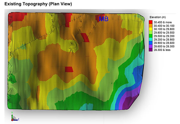
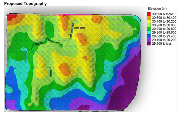
GPS landforming is the reshaping of a fields topography to predesigned 3D surfaces using high-accuracy GPS to control the blade height of the earth-moving machine. It is typically done to improve surface drainage and water infiltration uniformity.
Davco Optisurface, the company that developed the 3D landform design software OptiSurface Designer, has seen strong adoption as the concept catches on. The software has been used to design more than 400,000 acres, according to Arkansas-based global sales manager Preston Marthey.
WM-Form. Trimble launched a GPS landforming software program in February. WM-Form enables growers and contractors to turn their fields into optimal surfaces, even in areas that could not be leveled before, Trimble said.
“With more farmable land that is optimized for water management and more uniform production, growers can experience increased yield,” said David Fitzpatrick, Water Solutions business area director for Trimble’s Agriculture Division.
Trimble’s product is designed to work with its WM-Topo survey system and Trimble FieldLevel II system. WM-Form has surface design tools and flexible parameters so growers and earthworks contractors can use it to repair underperforming areas and extend the amount of productive farmable land. It can reduce the volume and cost of earthworks and minimize disturbance to valuable topsoil. Growers can optimize water distribution and drainage, reduce erosion and flooding by effectively directing waterflow, and create more uniform crop production that can lead to increased yield.
Growers can analyze topographic data in WM-Form to identify surface problems limiting yield potential and create a design that optimizes their field’s surface. The software also provides reports for volume, area and constraints, providing an accurate quote on the total cost of the project.
Horizon. Topcon’s Horizon software is an icon-based, user-definable system that presents a choice of views for each function you perform. It runs on all three of Topcon’s X family of precision agriculture consoles. With Horizon, growers can set autosteering patterns, control application rates, monitor operations, and map every pass — and a new feature allows for water management.
“Water conservation…is designed to provide the ability to perform land forming while also offering GNSS auto steering of the tractor,” said Neal Toso of Topcon Positioning. Using the Topcon X30 and AGI-4, water conservation and land forming users can level fields while auto-steering to maximize efficiency and reduce the amount of material moved, he said.
“With the X30 console, using Horizon software, connected to Topcon MC-R3 blade control, it is easy to take the output from Topcon AGForm 3D design software to produce accurate modeling and land forming. This allows proper drainage to occur, resulting in a healthy, productive crop,” said Toso. “Together, these Topcon products are designed to provide a turnkey approach to superior landforming operations.”
In Costa Rica, Jose Maria Aguero, CEO-director general of Agricultura Cientifica S.A., now uses Horizon. Aguero first employed laser leveling in the late 1970s. “We started noticing that rice and other crops produced less in areas with deep cuts from laser leveling because we had cut the more fertile topsoil off,” Aguero said. “But it was the only tool we had, so we kept doing it.”
Then Aguero discovered Topcon’s GPS land forming products. “Sugar cane crops are expanding dramatically in our area, and the operators don’t use irrigation. Water management is needed to improve drainage because in the rainy season it is too wet, which affects crop development. The only way the cane companies can get sugar cane into a new growing area is with GPS and 3D landforming,” he said.
“GPS with 3D landforming only moves 250 to 300 cubic meters per hectare,” Aguero said. Compared to laser leveling, “That is more than a 90 percent reduction in cost. And, moving less soil keeps more of the fertile top layer in place to promote fertility.”
Landforming Lessons
Surface drainage and irrigation problems can be solved with GPS landforming at low cost, agricultural engineer Graeme Cox says. This is proven with many crops and farming styles, irrigated and non-irrigated.
Cox has learned the following about GPS landforming, based on his experience around the world.
Water is king. Eighty percent of yield variability and profit loss is due to too much, or too little, water. Yield maps show this. “Focus on optimizing water management first,” Cox said.
Ponding kills profits. If water is standing in fields 24 hours after rainfall or irrigation, it is killing profits. “Expect eight percent per day yield loss plus nitrogen loss, increasing pest and disease, delaying planting, spraying and harvesting.”
Subsurface tile drainage is good, but expensive. “Tiling typically has a lower return on investment than GPS landforming and does not work well on heavy soils or those with limited elevation relief,” Cox said.
Ditching is good. “But,” he adds, “it can be a pain if ditches take out valuable crop area or restrict machinery access.”
Lasers are dead. Lasers only work in a straight plane. GPS allows farmers to follow curved topography with curved design surfaces.
Earthworks and topsoil movement can be reduced up to 80 percent with landforming designs and GPS machine control compared to other methods, Cox claims.
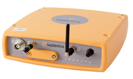
Septentrio this week is launching two successors to its APS-U: The AsteRx-U and the AsteRx-U Marine multi-constellation dual-antenna receivers. The AsteRx-U will be presented to the public for the first time at two trade shows this week. ION GNSS+ takes place Sept.14-18 in Tampa, Fla., and INTERGEO 2015 will be held in Stuttgart, Germany, Sept. 14-18.
The AsteRx-U and the AsteRx-U Marine incorporate the latest GNSS tracking and positioning algorithms and interference mitigation. Machine-control users in the agricultural and construction industries, as well as users in marine and mining industries, benefit from a complete system with integrated UHF radio, Wi-Fi, USB, Bluetooth and cellular connectivity and a spectrum analyzer, Septentrio said. All configurations can be done via the on-board web interface.
The AsteRx-U and AsteRx-U Marine feature a full range of positioning techniques and algorithms to ensure that users have the highest accuracy and reliability. The spectrum analyzer enables users to visualize the RF spectrum. Based on its extensive experience with real-life interference sources and their mitigation, Septentrio has developed interference mitigation technology that automatically counteracts various kinds of ambient intentional and unintentional RF interference.
The AsteRx-U family of receivers is built around Septentrio’s latest ASIC, GReCo4, which was introduced in 2014. It incorporates built-in jamming detection and countermeasures, multi-path rejection, fast acquisition and other advanced features. Both receivers have more than 500 hardware channels to track all available constellations (GPS, GLONASS, Galileo, Beidou, IRNSS and QZSS) and feature many algorithms: LOCK+ technology to maintain tracking during heavy vibration machine use and IONO+ technology to assure the accuracy of the position even in regions of elevated ionospheric activity.
The AsteRx-U has decimeter- and centimeter-level RTK positioning including TerraStar. The AsteRx-U Marine also supports Veripos PPP augmentation services. It includes extra anti-jamming technology to counter Iridium and INMARSAT-uplink interference, as well as an extra antenna connector for a dedicated L-band antenna to optimize L-band reception at high latitudes.
Straightforward to set up and integrate with existing systems, the AsteRx-U and AsteRx-U Marine use any device with a web browser to facilitate usability and configuration for the user.
“We want to make it easy for our customers to use high-accuracy positioning in their work,” said Jan Leyssens, Septentrio product manager. “Using the integrated communication functionality in the compact and portable AsteRx-U, users won’t have to worry about adding their own modems or UHF radios to get access to corrections.”
Leyssens continued, “The receiver web interface is available wirelessly on any mobile device. It was designed together with several of our key customers, resulting in an interface that is not only easy to use by field operators, but also provides many useful troubleshooting tools, such as the spectrum analyzer, to solve problems in the field and minimize downtime.”
Septentrio will be at Booth 318 at ION GNSS+, and at Hall: 4, Booth: D4.014, at INTERGEO.
Eos Positioning’s Arrow 200 Bluetooth receiver now supports Hemisphere’s Atlas correction service,
The Arrow 200 Bluetooth GNSS receiver by Eos Positioning Systems now supports the new Atlas H10 GNSS correction service. Using the H10 service, the Arrow 200 GNSS receiver is able to achieve 8-cm accuracy, in real-time, virtually anywhere in the world, the company said. The H10 corrections are delivered by geostationary satellite or via Internet connection.
The Hemisphere GNSS Atlas correction service, announced in June, is a real-time correction service that meets or exceeds existing correction services. It has three service levels, with H10 having the highest accuracy.
“Eos is proud to introduce the first GNSS receiver that supports the H10 service,” said Chief Technology Officer Jean-Yves Lauture. “It will allow our customers in every country in the world to have access to sub-decimeter real-time accuracy on all mobile platforms, including iOS, Android and Windows devices.”
The H10 correction service and the Arrow 200 support all active constellations including GPS, GLONASS, Galileo, BeiDou and QZSS, giving the user ultra-fast convergence time to real-time decimeter accuracy, Eos Positioning said.
The Arrow 200 employs long-range (1 km) universal Bluetooth connectivity so the user can interface to any brand of smartphone or tablet, whether it’s iOS, Android or Windows-based. The Arrow 200 has been optimized to run all day on battery power. The battery pack is field-replaceable and rechargeable separately. All Arrow receivers have been designed to meet IP-67 specifications for immersion in water and are completely dust-proof so they will survive in the harshest environments.
The Arrow 200 GNSS receiver with Atlas H-10 service is targeted at high-accuracy applications like GIS, environmental, agriculture, electric/gas/water utilities, surveying, machine control, and federal, state and local government.
ALTA is a smart balloon which flies without fuel or a pilot to up to 400 feet and is FAA compliant. It is held by a tether and transmits images and other data to any screen. ALTA services public safety, news agencies, agriculture, construction, real estate, travel and tourism.
Trimble is partnering with unmanned aircraft system (UAS) manufacturer Multirotor service-drone, GmbH. The collaboration will allow Trimble to expand its existing UAS portfolio to provide its customers with additional solutions to choose from based on their aerial imaging project needs.
Multirotor service-drone, based in Germany, is a manufacturer of multi-rotor systems. Trimble will be Multirotor service-drone’s exclusive provider of multi-rotor vehicles for aerial mapping use in surveying, construction, mining, agriculture, oil and gas, and utilities. The combination of Multirotor service-drone’s stable and reliable platforms with Trimble’s industry-leading sensor technology and workflow efficiencies will provide customers with best-in-class solutions for aerial data capture.
Unmanned multi-rotor systems are powerful solutions for visually documenting smaller areas, vertical structures or environments where holding position is important. High-resolution imagery, orthophotos, terrain models and normalized difference vegetation index (NDVI) map deliverables created from multi-rotor data provide valuable information for the survey, engineering and agriculture industries that Trimble serves.
“We are very excited to partner with Multirotor service-drone. At Trimble we’re always looking for ways to meet our customer’s needs and enable them to solve the complex problems they encounter every day,” said Todd Steiner, product marketing director in Trimble’s Geospatial Division. “The collaboration will enable our customers to use a technology rapidly growing in popularity due to its flexibility and productivity.”
Under the theme “Taking the Pulse of the Planet,” 275 members of the GEO community from more than 45 countries will chart the next steps in creating and implementing a Global Earth Observation System of Systems (GEOSS) during the Group on Earth Observations (GEO) Eleventh Plenary Session. The session will be held November 12-14 in Geneva, Switzerland.
A highlight of the conference will be announcement of the winners of the GEO Appathon, a global app development competition built on the 80-million-plus resources available through GEOSS. The Appathon attracted 250 competitors from 50 countries, and will generate easy-to-use decision tools for mobile devices and computers.
GEO’s mandate is to harness the power of Earth observations from sources across the globe to provide more and better information to leaders in government, industry, and civil society confronting fundamental decisions affecting people and societies worldwide. One key GEO initiative that will be highlighted during the meeting is developing a comprehensive system to monitor the availability and quality of fresh water, in partnership with the World Health Organization, the UN Environmental Programme and other UN agencies as part of the UN Sustainable Development agenda.
GEO is leading the creation of an Africa-wide technological and human infrastructure so decision makers have the capacity to access and use Earth observations in making key decisions. To strengthen agricultural activity and reduce market volatility, GEO is coordinating the assessment of growing conditions of the world’s major crops through a combination of regional expertise, ground observations and analysis of meteorological and satellite data.
GEO is a voluntary partnership of governments and organizations that envisions “a future wherein decisions and actions for the benefit of humankind are informed by coordinated, comprehensive and sustained Earth observations and information.” Members include 94 nations and the European Commission and 77 participating organizations comprised of international bodies with a mandate in Earth observations.
GEO’s agenda spans nine Societal Benefit Areas, including agriculture, biodiversity, climate, disasters, ecosystems, energy, health, water and weather.
Proteus FZC, a provider of satellite-derived mapping and classification services, will discuss its use of high-resolution WorldView-2 imagery to derive accurate forest inventory and tree classification maps in Abu Dhabi during a free webinar with DigitalGlobe.
“Vegetation Analysis in the Desert Using Satellite Imagery,” part of the ongoing DigitalGlobe LEAD Webinar Series, will be held September 24 at 12:30 p.m. BST (7:30 a.m. U.S. EDT). Register by clicking here.
The webinar is aimed at managers and technical analysts from forestry, agriculture, remote sensing and GIS organizations in private and public sectors. The webinar will cover:
How very high-resolution satellite remote sensing technology is being deployed commercially for tree inventory and condition analysis.
Tools that are available now to help agriculture, forestry and environmental decision makers in areas with sparse water resources.
How to use satellite data in support of environmental planning and policy creation.
Richard Flemmings, Proteus project manager, will offer insight into a recent 20-million tree mapping and classification project performed by Proteus FZC in Abu Dhabi. As an extension to an Emirate-wide habitat and land use/land cover project, Proteus applied advanced processing algorithms to the multispectral and panchromatic WorldView-2 image data to differentiate many tree species and assess the condition of individual trees, critical for irrigation management.
“This project demonstrates the viability of using very high-resolution satellite imagery to quickly and cost effectively create baseline vegetative inventories within diverse land-use areas,” said Flemmings. “The mapping technique used in Abu Dhabi can be applied to create forest and vegetation inventories of other species anywhere in the world.”
Since 2011, Proteus has been delivering solutions for mapping and classification projects using multispectral satellite imagery. These mapping projects have been delivered for environmental, oil & gas, engineering and other coastal zone applications in Europe, USA, the Middle East and Caribbean.
For more information on Proteus products, see www.proteusgeo.com or email [email protected] for further details or to discuss individual requirements.