Hyundai Motor America has selected Verizon Enterprise Solutions to provide a range of connected services including safety, security, diagnostics and infotainment to Hyundai vehicles starting in 2014.
“We selected Verizon to provide the wireless network service for ‘Next-generation Blue Link’ because both customer opinion and various data sources indicate that Verizon provides the best solution to our customers for both coverage and quality,” said Woo-Young Kwak of Hyundai Motor Group.
Hyundai vehicles are distributed throughout the United States by Hyundai Motor America and are sold and serviced through more than 820 dealerships nationwide. According to Forrester Research, the number of vehicles shipped worldwide with embedded connectivity is expected to grow from 5.4 million in 2012 to 36 million in 2018.
“Our agreement with Hyundai expands our long-standing collaboration with a wide range of auto manufacturers throughout the industry to support network engineering, security, cloud solutions, telematics platform, and program management for millions of vehicles in the U.S. and around the world,” said Mark Bartolomeo of Verizon Enterprise Solutions. “We are thrilled to be working with Hyundai to help enhance the driving experience for their customers. It’s the breadth of our expertise combined with the depth of our technology that allows our clients to launch new services and initiatives faster.”
Honda Motor Co. is joining an alliance of companies that will work with Google Inc. on technological innovations for inboard automotive information networks, such as GPS, according to The Asahi Shimbun. Honda will be joining Audi AG, General Motors, and Hyundai Motor Group in the Open Automotive Alliance. The alliance plans to incorporate Google’s Android operating system into automotive communications systems.
Google has also indicated interest in the development of driverless cars.
Toyota Motor Corp., meanwhile, established a joint venture with Microsoft Corp. three years ago to develop information technology for Toyota’s next-generation vehicles. The technology allows for updating map data and other services for the GPS in Toyota vehicles, as well as track stolen vehicles.
The implementation changes and first live tests of BeiDou and Galileo on Teseo-3 GNSS chips developed in 2013 are covered, bringing it to a four-constellation machine. By 2020, we expect to have four global constellations all on the same band, giving us more than 100 satellites — under clear sky, as many as 30 or 40 simultaneously.
By Philip G. Mattos and Fabio Pisoni
Multi-constellation GNSS first became widely available in 2010/2011, but only as two constellations, GPS+GLONASS. Although receivers at that time may have supported Galileo, there were no usable satellites. BeiDou was a name only, as without a spec (an interface control document, or ICD), no receivers could be built. However, the hardware development time of receivers had been effectively shortened: the Galileo ICD had been available for years, BeiDou codes had been reverse-engineered by Grace Gao and colleagues at Stanford, and at the end of 2011 they were confirmed by the so-called test ICD, which allowed signal testing without yet releasing message characteristics or content.
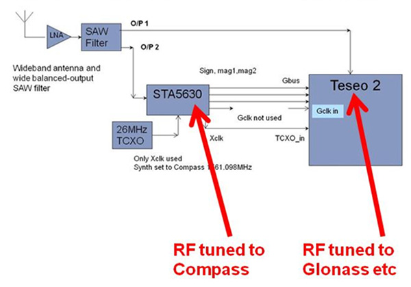
The last weeks of 2012 saw two great leaps forward for GNSS. Galileo IOV3 and 4 started transmitting at the beginning of December, bringing the constellation to four and making positioning possible for about two hours a day. At the end of December, the Chinese issued the BeiDou ICD, allowing the final steps of message decode and ephemeris calculation to be added to systems that had been tracking BeiDou for many months, and thus supporting positioning. The Teseo-2 receiver from STMicroelectronics has been available for some years, so apart from software development, it was just waiting for Galileo satellites; however, for BeiDou it needed hardware support in the form of an additional RF front end. Additionally, while it could support all four constellations, it could not support BeiDou and GPS/Galileo at the same time, as without the BeiDou ICD the spreading codes had to be software-generated and used from a memory-based code generator, thus blocking the GPS/Galileo part of the machine.
The Teseo-3 receiver appeared late in 2013, returning to the optimum single-chip form factor: RF integrated with digital silicon and flash memory in the same package, enabling simultaneous use of BeiDou and GPS/Galileo signals. Multi-constellation in 2012 was GPS+GLONASS, which brought huge benefits in urban canyons with up to 20 visible satellites in an open sky. Now, for two hours a day in Europe while the Galileo IOVs are visible, we can run three constellations, and in the China region, GPS/BeiDou/Galileo is the preferred choice.
This article covers the first tracking of four Galileo satellites on December 4, 2012, first positioning with Galileo, and first positioning with BeiDou in January 2013. It will cover static and road tests of each constellation individually and together as a single positioning solution. Road tests in the United States/Europe will combine GPS/GLONASS/Galileo, while tests in the China region will combine GPS/Galileo/BeiDou. Results will be discussed from a technical point of view, while the market future of multi-constellation hardware will also be considered.
In the 2010–2020 timeframe, GLONASS and BeiDou (1602 MHz FDMA and 1561 MHz respectively) cost extra silicon in both RF and digital hardware, and cause marginal extra jamming vulnerability due to the 50 MHz bandwidth of the front end. The extra silicon also causes extra power consumption.
After 2020, GLONASS is expected to have the L1OC signal operational, CDMA on the GPS/Galileo frequency, and BeiDou is expected both to have expanded worldwide, and also to have the B3 signal fully operational, again on 1575 MHz. At that point we will have four global constellations all on the same band, giving us more than 100 satellites. With a clear sky, the user might expect to see more than 30, sometimes 40, satellites simultaneously.
Besides the performance benefits in terms of urban canyon availability and accuracy, this allows the receiver to be greatly simplified. While code generators will require great flexibility to generate any of the code families at will, the actual signal path will be greatly simplified: just one path in both RF (analog) and baseband (digital) processing, including all the notch filters, derotation, and so on. And this will greatly reduce the power consumption.
Will the market want to take the benefit in power consumption and silicon area, or will it prefer to reuse those resources by becoming dual-frequency, adding also the lower-L-band signals, initially L5/E5, but possibly also L2/L3/L6 ? The current view is that the consumer receiver will go no further than L5/E5, but that the hooks will be built-in to allow the same silicon to be used in professional receivers also, or in L2C implementations to take advantage of the earlier availability of a full constellation of GPS-L2C rather than GPS-L5.
This article presents both technical results of field trials of the quad-constellation receiver, and also the forward looking view of how receivers will grow through multi-frequency and shrink through the growing signal commonalities over this decade.
History
Galileo was put into the ST GPS/GNSS receiver hardware from 2006 to 2008, with a new RF and an FPGA-based baseband under the EU-funded GR-PosTer project. While a production baseband (Cartesio-plus) followed in high volume from 2009, in real life it was still plain GPS due to the absence of Galileo satellites.
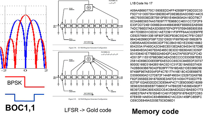
The changed characteristics in Galileo that drove hardware upgrades are shown in Figure 1. The binary offset carrier BOC(1,1) modulation stretches the bandwidth, affecting the RF, while both the BOC and the memory codes affect the baseband silicon in the code-generator area.
Figure 1. Changes for Galileo.
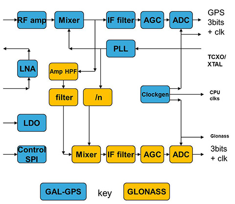
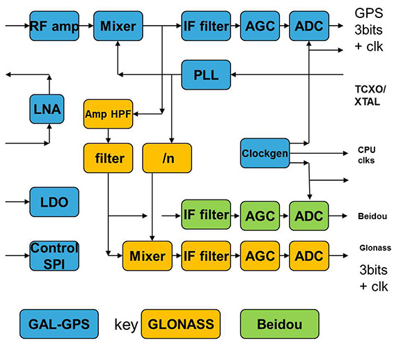
Next was the return to strength of the GLONASS constellation, meaning receivers were actually needed before Galileo. However the different center frequency (1602 MHz), and the multi-channel nature of the FDMA meant more major changes to the hardware. As shown in Figure 2 in orange, a second mixer was added, with second IF path and A/D converter.
Figure 2. Teseo-2 RF hardware changes for GLONASS.Figure 3. Teseo-2 and Teseo-3 baseband changes for GLONASS.
The baseband changes added a second pre-processing chain and configured all the acquisition channels and tracking channels to flexibly select either input chain. Less visible, the code-generators were modified to support 511 chip codes and 511kchips/sec rates.
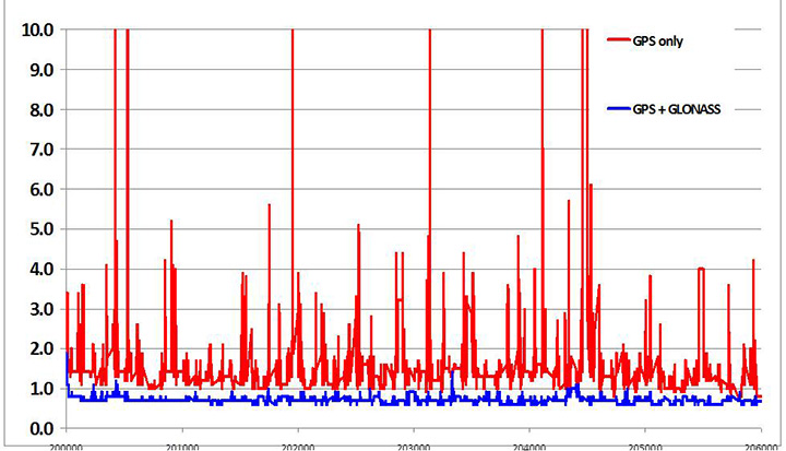
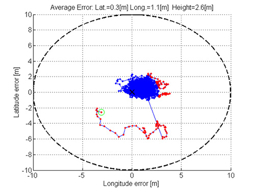
Teseo-2 appeared with GPS/GLONASS support in 2010, and demonstrated the benefit of GNSS in urban canyons, as shown by the dilution of precision (DOP) plot for central London in Figure 4. The GPS-only receiver (in red) has frequent DOP excursions beyond limits, resulting either in bad accuracy or even interrupted fix availability. In contrast, the GNSS version (in blue) has a DOP generally below 1, with a single maximum of 1.4, and thus 100 percent availability. Tracking 16 satellites, even if many are via non-line-of-sight (NLOS) reflected paths, allows sophisticated elimination of distorted measurements but still continuous, and hence accurate, positioning.
Figure 4. DOP/accuracy benefits of GNSS.
BeiDou
Like Galileo, BeiDou is a story of chapters. Chapter 1 was no ICD, and running on a demo dual-RF architecture as per the schematic shown in Figure 5. Chapter 2 was the same hardware with the test ICD, so all satellites, but still no positioning. Chapter 3 was the full ICD giving positioning in January 2013 (Figure 6), then running on the real Teseo-3 silicon in September 2013, shown in Figure 7.
Figure 5. Demo Teseo-2 dual RF implementation of BeiDou.Figure 6. Beidou positioning results.Figure 7. Teseo 3 development board.
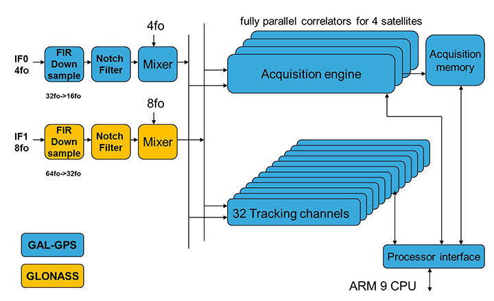
The Teseo-3 has an on-chip RF section capable of GPS, Galileo, GLONASS and BeiDou, so no external RF is needed.
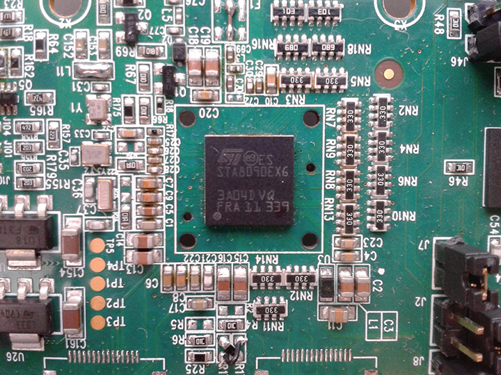
The clear green space around the Teseo-3 chip in the photo and the four mounting holes are for the bolt-down socket used to hold chips during testing, while the chip shown is soldered directly to the board. Figure 8A shows the development board tracking eight BeiDou satellites visible from Taiwan.
However, the silicon is not designed to be single-constellation; it is designed to use all the satellites in the sky. Figure 8b shows another test using GPS and BeiDou satellites simultaneously.
Figure 8A. Beidou.Figure 8b. GPS+Beidou.
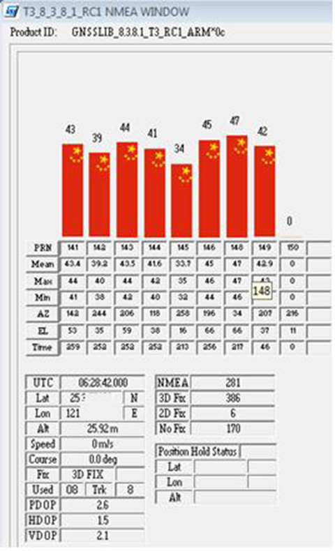
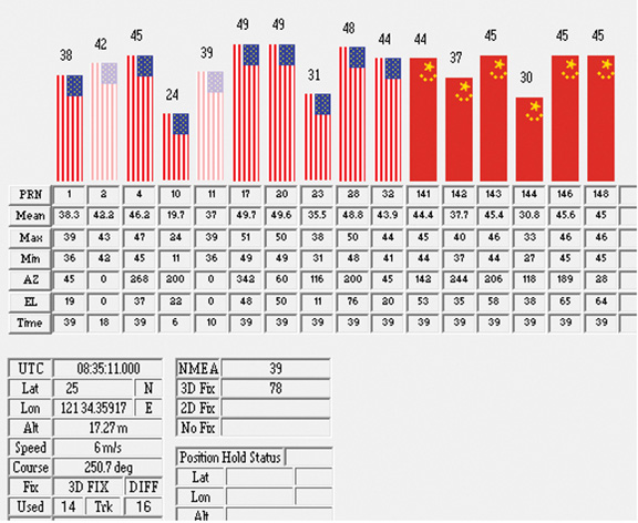
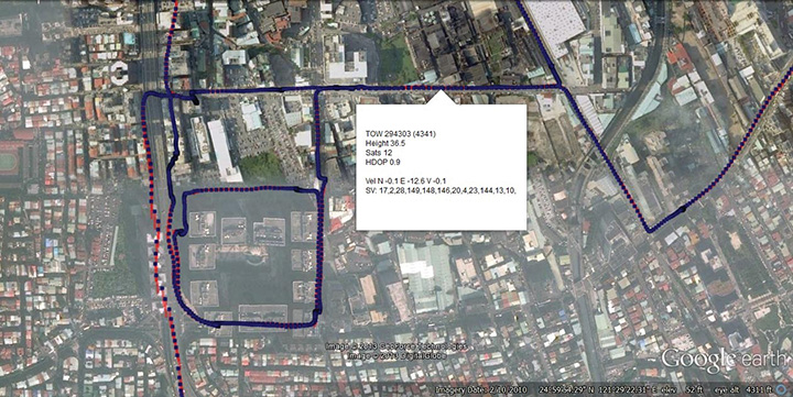
A mobile demo on the Teseo-3 model is shown running GPS plus BeiDou in Figure 9, a road test in Taipei. Satellites (SV) up to 32 are GPS, those over 140 are BeiDou, in the status window shown: total 13 satellites in a high-rise city area, though many are non-LOS.
Figure 9. GPS + Beidou roadtrack in Taipei.
Extending the hardware to add BeiDou, which is on 1561 MHz and thus a third center frequency, meant adding another path through the IF stages of the on-chip radio. After the first mixer, GPS is at 4 MHz, and GLONASS at about 30 MHz, but BeiDou is at minus 10 MHz. While the IF strip in general is real, rather than complex (IQ), the output of the mixer and input to the first filter stage is complex, and thus can discriminate between positive frequencies (from the upper sideband) and negative ones (from the lower sideband), and this is normally used to give good image rejection. In the case of BeiDou, the filter input is modified to take the lower sideband, that is, negative frequencies, and a second mixer is not required; the IF filter is tuned to 10 MHz. The new blocks for BeiDou are shown in green in Figure 10. The baseband has no new blocks, but the code generator has been modified to generate the BeiDou codes (and, in fact, made flexible to generate many other code types and lengths). Two forms of Teseo-3 baseband are envisaged, the first being for low-cost, low-current continues to have two input paths, so must choose between GLONASS and BeiDou as required. A future high-end model may have an extra input processing path to allow use of BeiDou and GLONASS simultaneously.
Figure 10. Teseo-3 RF changes for Beidou shown in green.
Galileo Again
Maintaining the chronological sequence, Galileo gets a second chapter in three steps. In December 2012, it was possible for the first time to track four IOV satellites simultaneously, though not to position due to the absence of valid orbit data. In March 2012, it was possible for the first time to demonstrate live positioning, and this was done using Teseo-2 simultaneously by ESA at ESTEC and STMicro in Naples and Milan, our software development centres.
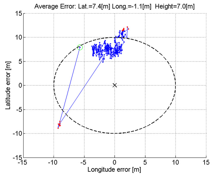
The demos were repeated in public for the press on July 24, 2013, at Fucino, Italy’s satellite earth station, with ESA/EC using the test user receiver (TUR) from Septentrio, and ST running simultaneous tests at its Italian labs. Figure 11 and Figure 12 show the position results for the data and pilot channels respectively, with independent LMS fixes. In real life, the fixes would be from a Kalman filter, and would be from a combined E1-B/E1-C channel, to take advantage of the better tracking on the pilot.
Good accuracy is not expected from Galileo at this stage. The four satellites, while orbited to give good common visibility, do not also give a good DOP; the full set of ground monitoring stations is not yet implemented and cannot be well calibrated with such a small constellation. Finally, the ionospheric correction data is not yet available. Despite these problems, the residuals on the solutions, against a known fixed position for the rooftop antenna, are very respectable, shown in Figure 13.
Figure 13. Galileo residuals, L1-B.
The common mode value is unimportant, representing only an offset in the receiver clock, and 10 meters is about 30 nanoseconds. The accuracy indicator is the spread between satellites, which is very respectable for a code-only receiver without full iono correction, especially around 640 on the TOW scale, where it is less than 2 meters. The rapid and major variation on the green data around t=400 is considered to be multipath, as the roof antenna is not ideally positioned with respect to other machinery and equipment also installed on the roof.
QZSS and GPS-III/L1C
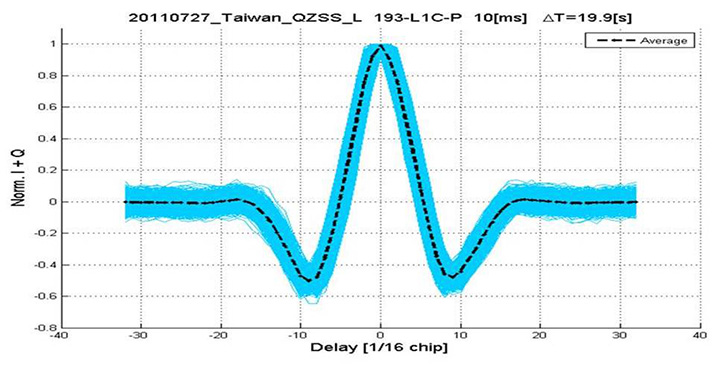
Teseo-2 has supported the legacy (C/A code) signal on QZSS for some time, but Teseo-3 has been upgraded to handle the GPS-III/L1-C signal, waiting for modernized GPS. This signal is already available on the QZSS satellite, allowing tests with real signals. Significant changes were required in the baseband hardware, as the spreading code is a Weill code, whose generation complexity is such that it is generated once when the satellite is selected, then replayed real time from memory. Additionally it is long, in two domains. It is 10230 chips — that is, long to store but also long in time, with a 10-millisecond epoch. On Teseo-3, the legacy C/A code is used to determine code-phase and frequency before handing over to the Weill code for tracking.
Using a long-range crystal ball and looking far into the future, a model of the future Teseo-4 DSP hardware is available, with 64 correlation taps per satellite. Running this on the captured QZSS L1-C signal gives the correlation response shown in Figure 14. Having multiple taps removes all ambiguity from the BOC signal, simultaneously removing data transitions, which can alternatively be pre-stripped using the known pilot secondary code (which on GPS III is 5 dB stronger than the data signal). The resultant plot represents 2,000 epochs, each of 10 milliseconds, plotted in blue, with integrated result for the full 20 seconds shown in the black dashed line. Assuming vehicle dynamics is taken out using carrier Doppler, this allows extremely precise measurement of the code phase, or analysis of any multipath in order to remove it. This RF data was captured on a benign site with a static antenna, so it shows little distortion.
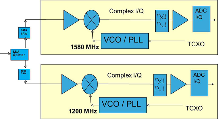
Figure 14. L1-C tracking on QZSS satellite.Figure 15. Dual RF implementation of dual-band front end.
The Future
Having already built in extreme flexibility to the code generators to support all known signals and generalized likely future ones, the main step for the future is to support multiple frequencies, starting with adding L5 and/or L2, but as before, ensuring that enough flexibility is built in to allow any rational user/customer choice. It is not viable for us to make silicon for low-volume combinations, nor to divide the overall market over different chips. Thus our mainstream chip must also support the lower volume options.
We cannot, however, impose silicon area or power consumption penalties on the high-volume customer, or he will not buy our product.
Thus, our solution to multi-frequency is to make an RF that can support either band switchably, with the high band integrated on the volume single-chip GNSS. Customers who also need the low band can then add a second RF of identical design externally, connected to the expansion port on the baseband, which has always existed for diagnostic purposes, and was how BeiDou was demonstrated on T2. By being an RF of identical design to the internal one, it incurs no extra design effort, and would probably be produced anyway as a test chip during the development of the integrated single-chip version. Without this approach, the low volume of sales of a dual-band radio, or a low-band radio, would never repay its development costs.
Conclusions
All four constellations have been demonstrated with live satellite signals on Teseo-2, a high-volume production chip for several years, and on Teseo-3 including use in combinations as a single multi-constellation positioning solution. With the advent of Teseo-3, with optimized BeiDou processing and hardware support for GPS-3/L1C, a long-term single-chip solution is offered.
For the future, dual-frequency solutions are in the pipeline, allowing full advantage of carrier phase, and research into moving precise point positioning and real-time kinematic into the automotive market for fields such as advanced driver-assistance systems.
Acknowledgments
Teseo III design and development is supported by the European Commission HIMALAYA FP-7 project.
This article is based on a technical paper first presented at ION-GNSS+ 2013 in Nashville, Tennessee.
ST GPS products, chipsets and software, baseband and RF are developed by a distributed team in: Bristol, UK (system R&D, software R&D; Milan, Italy (Silicon implementation, algorithm modelling and verification); Naples, Italy (software implementation and validation); Catania, Sicily, Italy (Galileo software, RF design and production); Noida, India (verification and FPGA). The contribution of all these teams is gratefully acknowledged.
Philip G. Mattos received an external Ph.D. on his GPS work from Bristol University. Since 1989 he has worked exclusively on GNSS implementations, RF, baseband and applications. He is consulting on the next-generation GNSS chips, including one-chip GPS (RF+digital), and high-sensitivity GPS and Galileo for indoor applications, and combined GPS/Galileo/GLONASS chipsets. In 2008-2009, he re-implemented LORAN on the GPS CPU, and in 2009-2010 led the GLONASS implementation team. He is leading the team on L1C and BeiDou implementation, and the creation of totally generic hardware that can handle even future unknown systems.
Fabio Pisoni has been with the GNSS System Team at STMicroelectronics since 2009. He received a master’s degree in electronics from Politecnico di Milano, Italy, in 1994. He was previously with the GNSS DSP and System Team in Nemerix SA and has earlier working experience in communications (multi-carrier receivers).
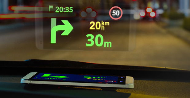
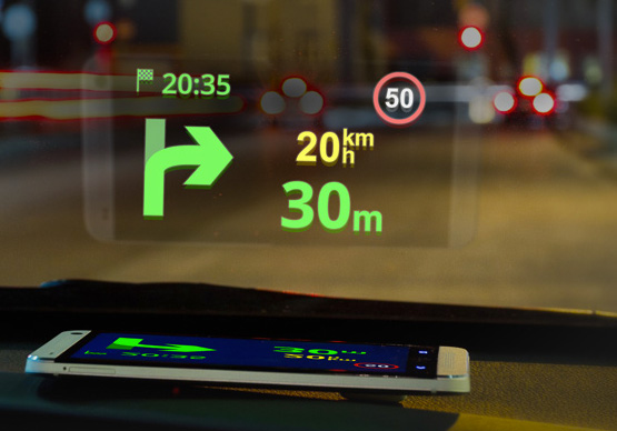
Sygic has announced a new product to make driving safer. Sygic’s Heads-up-Display (HUD) product projects navigation information onto drivers’ windshields, so they never have to take their eyes off the road to look down at their navigation software.
The product comes at a critical time for the holiday travel and shopping season, which is one of the most auto accident-heavy periods of the year. Sygic’s HUD is available as an in-app purchase for $4.99 and doesn’t need an expensive add-on product, as the projection can be emitted right from the Sygic GPS Navigation app on any iOS and Android phone or tablet.
Using Sygic’s HUD interface is straightforward. Drivers activate the feature from the app’s navigation menu, flip the screen via pop-up menu, and place their phone on their dashboard. The specially optimized interface will then
reflect clearly on the car’s windshield, displaying navigation information without the need for any expensive accessories. Sygic’s HUD feature gives them the full Sygic experience, complete with features like live traffic and turn-by-turn voice guidance.
“As we head into the heavy travel season, we hope our HUD will help drivers stay safe on the roads so they can spend more time with their family and friends and less time driving down heavily-trafficked and dangerous winter road conditions,” said Sygic CEO Michal Štencl.
Features of Sygic GPS Navigation include:
• Offline maps that don’t require a cellular data connection
• Turn-by-turn voice-guided GPS navigation
• 3D cities and landscapes
• Voice guidance in more than 40 languages
• Multi-stop routes and Drag & Drop route editing
• Speed limit display and audio warning
• SOS/Help to find assistance nearby
• Interactive map – tap on any street, POI, or photo to choose action
• Robust integration with third party
services like Groupon and TripAdvisor to find
things like deals, restaurants, hotels, attractions and more
• New speed cameras feature with a
constantly-updated database of stationary and mobile speed traps
Unlike other map services, data in Sygic: GPS
Navigation is stored on the user’s phone instead
of streamed from the Internet, which means that
Sygic users don’t have to worry about running up
against their cellular data caps by using GPS
navigation or getting lost in an area with poor
cell reception. When Sygic’s users are online,
they now have access to other helpful features
like real-time traffic and road incident sharing with other drivers.
Sygic GPS Navigation, now upgraded to version
13.3, is available in the iOS App Store and
Google Play, while the HUD feature can be
purchased from within the app for $4.99.
– See more at:
http://www.gisuser.com/content/view/31596/2/#sthash.goudUtyE.dpuf
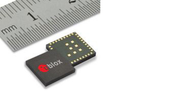
Swiss-based u‑blox has introduced its smallest standalone GNSS positioning module, the EVA-7M. Designed for cost and space sensitive applications, the highly integrated 7 x 7 x 1.1 mm LGA module comprises all necessary components, including crystal and passives: only an antenna is needed for global positioning capability.
The module supports GPS, GLONASS, QZSS, and all SBAS augmentation systems. Based on u-blox’ advanced GNSS technology u‑blox 7, the module achieves -160 dBm sensitivity when tracking GPS satellites (-158 dBm with GLONASS satellites), fast acquisition time and the lowest power of any u-blox 7 module (16.5 mA at 3 V), thanks to an innovative high-efficiency power converter.
The EVA-7M eases implementation in end-products because RF and digital domains are kept well separated, and the LGA pads are configured in single rows. EVA is a standalone GNSS receiver which provides a position without the need for host integration or extra RF components. It is optimized for keeping eBOM and system costs to an absolute minimum.
“The EVA-7M brings embedded satellite positioning to the next level of portability. The module has been developed with ease-of-manufacturing as a high priority. Its QFN-like footprint with connections along four sides and high-level of component integration makes it a perfect solution for medium and high volume production runs. This ensures high first-pass production yield, crucial criteria especially for cost-sensitive, high-volume industrial and consumer applications,” said Thomas Nigg, VP Product Marketing at u-blox.
A UART, USB, SPI and I2C interface provide flexible connections to a host processor. EVA-7M can also communicate directly with u‑blox’ SARA 2G, LISA 3G and TOBY LTE cellular modules to support advanced tracking and location-aware applications.
The module is suitable for consumer, industrial, and after-market vehicle applications. First samples will be available in Q1 2014.
ABI Research forecasts that the global market for Driver Monitoring Systems (DMS) will reach 64.8 million units by the end of 2020 with the majority of shipments being accounted for in vehicles sold in the Asia-Pacific region. These findings are part of ABI Research’s Intelligent Transportation Systems Research Service and includes detailed installed base and forecasts of ADAS systems [advanced driver assistance systems] by regions.
Driver Monitoring Systems were first introduced as far back as 2006 when Toyota launched its innovative Driver Attention Monitor system. Toyota’s system functions by directly monitoring the driver’s face using a discrete in-dash camera and was initially offered as an option in the company’s luxury Lexus models. Other OEMs soon followed suit and announced their own DMS systems which were typically based on monitoring the vehicle rather than the driver’s face.
“DMS systems such as Mercedes-Benz’s ’Attention Assist’ and Volvo and Volkswagen’s ’Driver Alert’ systems were the first ADAS systems to be offered as standard equipment by OEMs, albeit only in a small selection of models,” comments Gareth Owen, principal analyst at ABI Research.
Today, an increasing number of ADAS systems are gradually becoming standard equipment in new cars, particularly in some European and Japanese brands such as Volvo, Mercedes-Benz, Nissan Infiniti, Lexus, and Mazda, and more are being offered as options. Although some of the big U.S. brands offer ADAS features in their European models, they typically do not offer the same features in their U.S. models, although this is beginning to change. Ford is a good example of this with its Ford Focus model.
“Another very observable trend in 2013 is that ADAS features are migrating from the luxury brands into B, C, and even A segment cars. Typically, the focus here is on offering ADAS systems, mostly as options, designed specifically for low-speed urban driving,” adds Owen.
Prices are decreasing, too. For example, the European Ford Focus offers an emergency braking system plus lane departure warning and lane-keep assist, driver alert, and blind spot monitoring as an optional package for £550 ($880) in the UK. Meanwhile, Volkswagen offers its City Emergency Braking System for £225-£405 ($360-$648), depending on model, on its budget A segment Up! car. This uses a laser sensor to detect the risk of an imminent collision and is active at speeds under 30 km/hr (18 mph).
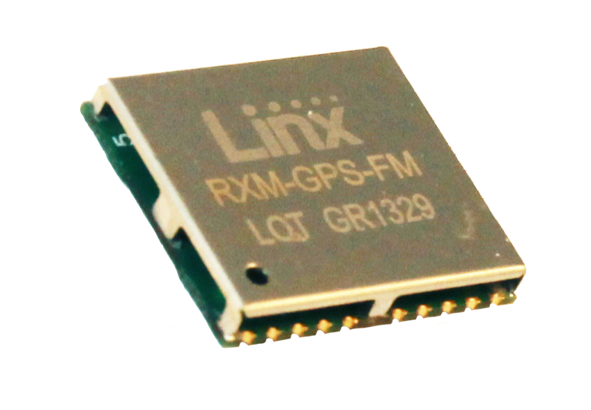
Linx Technologies announces its launch of the self-contained, high-performance FM GPS receiver modules. At 15 x 13 millimeters in size, the MediaTek MT3339-based FM Series gives the module fast lock times and high position accuracy even at low signal levels, the company said.
The module’s very low power consumption helps maximize run times in battery powered applications, such as positioning and navigation, location tracking, marine, and asset management, according to Linx Technologies.
Using the built-in MediaTek MT3339 chipset, The FM module can simultaneously acquire on 66 channels and track on up to 22 channels, providing standard NMEA data messages through a UART interface. A simple serial command set can be used to configure optional features.
The GPS receiver is completely self-contained and only requires an antenna. It powers up and outputs position data without any software set-up or configuration. As a result, the FM Series is easy to integrate, the company said.
With built-in hybrid ephemeris prediction technology, the FM Series predicts satellite positions for up to three days and delivers start times of less than 15 seconds under most conditions.
In addition, the available GPS Master Development System connects a FM Series Evaluation Module to a prototyping board with a color display that shows coordinates, speedometer and compass for mobile evaluation. A USB interface allows simple viewing of satellite data and Internet mapping, as well as custom software application development.
Parsec Technologies, Inc., today announced that the company’s Micro-Mini PTA/PT family of GNSS/GPS receiver modules seamlessly integrates with the Telit Wireless Solutions Jupiter SE880 three-dimensional system-in-a-package (3D-SIP) to enable what it calls the world’s smallest- to-date, commercial-class, low-cost GPS L1 receiver.
By combining a PTA/PT family module with the Jupiter SE880 3D-SIP, OEMs and integrators are able to deliver a location-based service product with a GPS L1 receiver in a landed form factor of 20 x 20 x 6 millimenters, or 20 x 10 x 6 millimeters, depending upon component orientation. This contrasts with landed GPS receiver sizes integrating a passive ceramic patch antenna that measure 25 x 25 millimeters, and which Parsec says don’t match the GNSS/GPS frequencies in performance despite being four times the surface area.
With the Parsec/Jupiter combination, integrators can design LBS-critical products with exceptional user experience in applications with severe use, such as obstructed satellite view and high path loss, including indoors, urban canyons, wearables, smart watches, vehicle under-dash on board diagnostics (OBD) devices, metal containers and aircraft fuselage asset tracking, and M.2/next-generation form factor (NGFF) products.
Receivers combining Parsec PTA/PT Family and Telit Jupiter SE880 modules deliver good user experience in finished LBS critical products without sacrificing design flexibility, ease of implementation, or cost, Parsec said. The combination is fully vetted and “bulletproof” in providing a rewarding design experience making RF work reliably, passing end-product regulatory compliance testing without re-test.
According to Michael A. Neenan, CEO and founder of Parsec, customers are future-proofing their LBS critical products when they select a Parsec PTA/PT family for integration with the Telit Jupiter SE880 3D-SIP. PTA/PT family modules receive and amplify any GNSS system signal from 1560 to 1610 MHz, including GPS L1/L1C, with high radiated efficiency in any end product orientation.
Telit Jupiter SE880 reference design kits will soon be equipped with the Parsec PTA/PT family module. OEMs and integrators can order GPS L1 receiver solutions today.
The PTA/PT family of GNSS/GPS receiver Micro-Mini modules extends Parsec’s decade-long tradition of stretching the state-of-the-art in small size, ultra-linearity, miniscule energy usage, high gain, low noise, Any Voltage operation, Field-and-Forget reliability, low cost, and ease of integration/use.
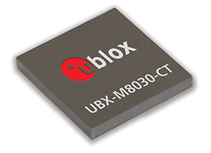
u‑blox has announced the launch of its newest core positioning platform, the u-blox M8. The new chip forms the basis of u-blox’ upcoming line of positioning modules, which are able to acquire and track different satellite systems concurrently to achieve higher accuracy and reliability.
Supporting all deployed as well as upcoming GNSSs, the platform is based on the UBX-M8030 concurrent multi-GNSS receiver IC which is able to track American GPS, European Galileo, Japanese QZSS, Russian GLONASS, and Chinese BeiDou satellites.
Concurrent tracking of GPS (QZSS) and GLONASS or BeiDou, or concurrent tracking of GLONASS and BeiDou satellites increases performance for applications requiring maximum availability and accuracy. The chip is prepared for the European Galileo system through a future firmware upgrade once the constellation is fully available.
The new platform will ultimately support special functions such as Automotive Dead Reckoning and precision timing to support a wide variety of vehicle, industrial and consumer applications.
To further improve acquisition performance, u-blox’ globally available “AssistNow”assisted-GNSS service for accelerated positioning has been extended for u-blox M8 products; the service supports both GPS and GLONASS, and the validity of downloaded assistance data is now able to support offline operation for up to 35 days.
“With the proliferation of multiple new GNSS systems beyond GPS, our u-blox M8 platform is designed to take full advantage of the increasing number of visible satellites to further increase accuracy and availability, particularly in urban and vehicle-based applications,” said Daniel Ammann, executive vice president, head of the Positioning Product Centre, and co-founder of u-blox, “At the same time we realize the ongoing requirement for extremely low-power and cost-sensitive portable applications where operation with a single GNSS system is more than sufficient. That is why we will continue to offer both u-blox M8 and u-blox 7 based products to the market.
The new u-blox M8 chip is at the heart of u-blox’ next generation of positioning modules based on the company’s popular MAX, NEO and LEA module form factors.
u-blox M8 chips feature low power consumption in concurrent reception mode, thanks to an innovative single-die architecture combined with sophisticated software algorithms. The extended supply voltage supply range and 1.8 V/3.0 V I/O compliance supports a wide variety of system architectures. Sophisticated radio architecture and interference suppression using active jamming detection ensure maximum performance even in GNSS hostile environments. UBX-M8030 chips are available in miniature WL-CSP (2.99 x 3.21 x 0.36 mm) and QFN (5.00 x 5.00 x 0.59 mm) packages. The chip is also available in automotive quality grade according to AEC-Q100.
The new platform maintains backwards compatibility with u-blox 7 modules and QFP chip products which remain in the company’s portfolio as the industry’s lowest power standalone satellite positioning receivers. u‑blox’ capability of delivering GNSS technology in both integrated circuit and form-factor consistent modules provides maximum design flexibility and protects customers’ development investments over successive product generations.
First samples of the multi-GNSS receiver chip UBX-M8030 are available for customer evaluation. Soon, module customers can easily migrate to the MAX, NEO, and LEA form factors, u-blox’ popular, industry-standard module form factors.
Ford is studying communications between space robots and Earth to enhance future applications of the connected-car communications protocol. The research furthers the company’s commitment to the development of connected vehicle communications to help reduce traffic congestion and aid in the advancement of emergency vehicle communication methods, Ford said.
Ford has launched a three-year research partnership with the telematics department of St. Petersburg Polytechnic University in Russia in its association with that country’s space industry. The goal is to analyze space-based robotic communications systems for vehicle mesh networks to aid in mobility solutions.
The development of connected vehicle communications has the potential to reduce traffic accidents and ease congestion by enabling vehicles to communicate with each other, and to communicate with buildings, traffic lights, the cloud and other systems to deliver a message or detect and respond to imminent collision warnings.
All major international car-makers are installing telematics units, sending a signal that wireless information and connectivity is here to stay in the vehicle, and location will be a big part of the growth. To learn more about the rapid changes in the connected vehicle field, tune in to our September 19 webinar, hosted by Wireless LBS editor Janice Partyka. Registration is free.
“Ford has been committed to the research and development of connected vehicle communications for more than a decade,” said Paul Mascarenas, chief technical officer and vice president, Ford research and innovation. “Our participation in this research can aid in the development of next-generation Ford driver-assist technologies. These technologies will globally benefit Ford customers, other road users and the environment.”
Emergency Situations. One promising development from Ford’s research project with St. Petersburg Polytechnic University is the advancement in emergency vehicle communication methods. Ford is analyzing how emergency messages should be sent to ensure delivery if network failures were to occur, identifying the systems and methods that provide redundancy in case of primary delivery failure.
For example, if an accident were to cause vehicle-to-cloud communications (V2C) to be broken, a vehicle may still have access to a vehicle-to-vehicle (V2V) communications network. An emergency signal message could potentially be sent through V2V to a vehicle nearby, and then between vehicles and infrastructures until it reached EMS.
“The research of fallback options and robust message networks is important,” said Oleg Gusikhin, technical leader in systems analytics for Ford. “If one network is down, alternatives need to be identified and strengthened to reliably propagate messages between networks.”
Space Telematics. Telematics — the long-distance transmission of digital information — developed for use on space stations provide excellent potential for improving the reliability of future vehicle-to-cloud, vehicle-to-infrastructure, vehicle-to-vehicle and other forms of communication (V2X). The communications blend multiple networking technologies including dedicated short-range communication (DSRC), cellular LTE wireless broadband and mesh networking to ensure robust and reliable connectivity for optimum signal strength for critical messages.
Using the knowledge accrued from analyzing the space robots, Ford engineers could then develop an algorithm that is integrated into the V2X system resulting in a message that would route through the appropriate network depending on the level of its importance. An emergency message, for example, may be communicated through the faster mesh network, whereas an entertainment-related message would route through a vehicle-to-infrastructure application, an embedded device or a brought-in device network.
“We are analyzing the data to research which networks are the most robust and reliable for certain types of messages, as well as fallback options if networks were to fail in a particular scenario,” said Oleg Gusikhin, technical leader in systems analytics for Ford. “In a crash, for example, a vehicle could have the option to communicate an emergency though a DSRC, LTE or a mesh network based on the type of signal, speed and robustness required to reach emergency responders as quickly as possible.”
Here is a video showing how Ford is studying space robot communications.
Findings from this work could potentially enhance Ford’s wireless communication technologies and Blueprint for Mobility. Ford’s Blueprint for Mobility details the company’s vision on how to tackle the issues of mobility in an increasingly crowded and urbanized planet between now and 2025.
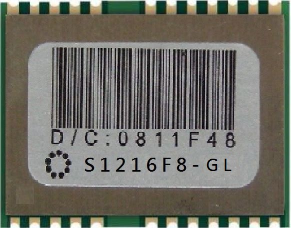
SkyTraq Technology, Inc., a fabless GNSS positioning technology company, has introduced its fast consumer-grade 50-Hz update rate S1216F8 GPS receiver module. The module supports GPS, QZSS, WAAS, EGNOS, MSAS, and GAGAN satellite signal reception. The S1216F8 receiver is based on SkyTraq’s newest 55-nm Venus 8 GPS/GNSS chipset.
The Venus 8 is a low-cost commercial GPS/GNSS chipset incorporating an IEEE-754 compliant FPU. With RISC/FPU running at 100 MHz, the S1216F8 GPS receiver module has industry leading 50-Hz update rate, very fast and accurate position/speed response, suitable for UAV, RC plane flight logging, and high-performance race car or speed boat data logging applications. When running at lower 1 Hz, 5 Hz, or 10 Hz update rate, the S1216F8 receiver can be used as a typical GPS receiver module currently available on the market.
The S1216F8 GPS receiver module measures 12mm x 16mm and consumes 26mA @ 3.3V during continuous navigation at 50-Hz update rate.
The S1216F8 is among SkyTraq’s S1216 family of form factor compatible, high-performance, low-cost GNSS modules. The S1216F8-GL GLONASS/GPS module and S1216F8-BD Beidou/GPS module both have a 20-Hz update rate.
The S1216 family of 50-Hz GPS, 20-Hz GLONASS/GPS, and 20-Hz Beidou/GPS receiver modules are in production. Datasheet, engineering sample, evaluation kit and reference design are available.
Sirius XM Radio has entered into a definitive agreement to acquire the connected vehicle services business of Agero, Inc. for $530 million in cash.
The connected vehicle unit of Agero is a leading provider of innovative telematics services, according to Sirius, offering safety, security and convenience services for drivers and end-to-end, turnkey solutions for automakers. Following the acquisition, SiriusXM will provide connected vehicle services to numerous automotive manufacturers, including Acura, BMW, Honda, Hyundai, Infiniti, Lexus, Nissan, and Toyota.
All major international car-makers are installing telematics units, sending a signal that wireless information and connectivity is here to stay in the vehicle, and location will be a big part of the growth. To learn more about the rapid changes in the connected vehicle field, tune in to our September 19 webinar, hosted by Wireless LBS editor Janice Partyka. Registration is free.
SiriusXM offers “unparalleled audio entertainment and data services available in more than 50 million vehicles,” the company said in a statement. “Telematics and connected vehicle solutions are key elements in the future of the auto industry. The acquisition of the connected vehicle business of Agero establishes SiriusXM as the leading provider for services in this growing industry.”
“The acquisition of Agero’s connected vehicle business is a natural fit for Sirius XM,” said Jim Meyer, Chief Executive Officer, SiriusXM. “As the world’s leading provider of in-vehicle subscription services, SiriusXM is uniquely positioned to offer world-class end-to-end telematics services.”
Meyer said the transaction accelerates SiriusXM’s development in architecture supporting connected vehicle services, as well as the ability to provide services over both satellite and cellular networks. “Agero’s connected vehicle team is known for their experience, innovation and technology, and we look forward to welcoming them to SiriusXM as we work to capture the significant growth opportunities in connected vehicle services.”
The transaction is subject to the expiration or early termination of the Hart-Scott-Rodino antitrust waiting period and other customary closing conditions. The transaction is expected to close in the fourth quarter of 2013. Morgan Stanley acted as financial advisor to SiriusXM in connection with this transaction.