GNSS CORS network to be established on university grounds
Global GIS (Pvt) Ltd, a pioneer in geospatial positioning solutions in Sri Lanka, has entered a Memorandum of Understanding with the University of Ruhuna to collaborate with the Department of Civil and Environmental Engineering and the Department of Electrical and Information Engineering of the Faculty of Engineering.
Areas identified for collaboration include conducting research and development activities, developing and commercializing new inventions and solutions, industry projects and consulting opportunities, and disseminating scientific knowledge to meet the growing demand of surveying and geospatial technologies and to increase efficiency and sustainability in the nation’s engineering industries and its thematic requirements.
“We are honored to enter this mutually beneficial collaboration with the University of Ruhuna to enhance capacity and support the growing geospatial and surveying industry in Sri Lanka,” said Nishshanka De Silva, sureyor and CEO-managing director of Global GIS. “We aim to take the industry in Sri Lanka to the next level with new innovative products and solutions while building sufficient capacity to undertake the country’s next phase of growth. Geospatial and surveying technology plays a significant role in sustainable infrastructure planning, renewable energy, disaster management, optimizing natural resource allocation, and many other areas as Sri Lanka pursues its national development goals.”
Under the MOU, Global GIS will establish a high-precision GNSS Continuously Operating Reference Station (CORS) network station at the university to enhance the university’s capacity for advanced GNSS-based research and applications to promote GNSS technology among government, semigovernment, and private organizations.
Global GIS will also open a funding avenue to
support research and development activities for the duration of the agreement,
provide necessary commercialization experience and business knowledge for new inventions and solutions,
conduct training and internship opportunities for the undergraduates on surveying and geospatial technologies to foster skill development and practical experience, and
leverage its “Authorized Agent” status for the brands it promotes in Sri Lanka to enhance the University of Ruhuna’s capacity in the latest surveying and geospatial technologies.
Researchers at the University of Tehran have developed indigenous software for providing real-time corrections for networks, precise positioning service and online processing of GNSS observations.
According to variousnews reports, the software is a modern, secure, and intelligent platform for processing observations from global positioning satellites, including GPS, Galileo, BeiDou and GLONASS.
Developed as a practical tool for surveyors, engineers, researchers and organizations in the field of satellite data monitoring, the software is intended to replace imported software and reduce dependence on foreign technologies. It has been tested by the network of permanent stations of the National Iranian South Oil Company.
The system processes observations using static, PPK, PPP and SPP methods, as well as observation quality control and enables the implementation of various positioning methods and real-time monitoring of ionospheric and tropospheric effects.
It supports all GNSS data types and can connect to reference stations in both client and server modes. It supports all existing and future GNSS signals and can handle at least 50 permanent stations and 200 users simultaneously. It also provides phase ambiguity resolution for baselines up to 70 kilometers.
Other technical features include providing a relative planimetric accuracy of 2 cm and a height accuracy of 3 cm using the static method with a maximum setup time of 15 minutes, a relative planimetric accuracy of 4 cm and a height accuracy of 5 cm using PPK and NRTK methods, and delivering corrections with a maximum permissible latency of 0.5 seconds.
The software has the capability to connect to reference stations through serial, TCP, and UDP ports, supports NTRIP protocol versions 1 and 2, displays an online map with a Google Map-like background, allows for viewing the location, status and information of CORS stations and active users, and enables generation of KML outputs.
Genesys has developed India’s first large-scale high-definition maps engineered specifically for vehicles enabled with advanced driver assistance systems (ADAS).
Covering more than 1 lakh km of India’s national highways, expressways and strategic corridors, this initiative marks one of India’s most ambitious road intelligence programs and establishes a new benchmark for automotive-grade precision.
India’s highways account for a disproportionately high share of road fatalities, driven by fast-moving traffic, inconsistent lane discipline, and limited real-time awareness for drivers and vehicles. HD maps narrow this gap by adding the centimeter-level context that traditional maps cannot provide — lane geometry, curves, slopes, signage, barriers and localization cues that help ADAS systems anticipate danger instead of merely reacting to it. This is a big leap forward from current sensor-based ADAS systems, Genesys said.
The HD maps include ADAS-critical features such as lane geometry, road markings, barriers, signage, medians, elevation and curvature profiles, and localization objects like poles and gantries — all processed to achieve centimeter-grade precision.
CORS network plays a key role
To achieve the centimeter-level accuracy required for ADAS Level 2 functionality, Genesys relies on the Survey of India’s Continuously Operating Reference Stations (CORS) network. Real-time GNSS correction signals along major corridors dramatically strengthen field operations, allowing survey teams to capture lane-level and asset-level detail that meets global automotive standards.
This work builds on the existing memorandum of understanding between Genesys and Survey of India, enabling collaboration on digital twin projects, national mapping programs, and high-accuracy geospatial missions.
These datasets are owned by Genesys and can be licensed across industries, creating opportunities in commercial fleet navigation, logistics optimization, mobility platforms, safety analytics and automotive R&D.
The challenge of repairing GNSS stations in Bangladesh is recounted in a Nov. 6 article by Mike Steckler, a researcher with Columbia Climate School.
Steckler has been conducting research in the country for 25 years. He previously installed a continuously operating reference station (CORS) network in the southern region of the country.
Data from the network has enabled study of the tectonic motions of the Earth leading up to earthquakes. It also revealed the sinking of the land in the world’s largest delta to less than 1 mm/y.
“I still find that amazing compared to the days before GNSS became routine,” he writes. “I’ve been at sea where the crew had to use sextants to estimate our position to within 10 miles.”
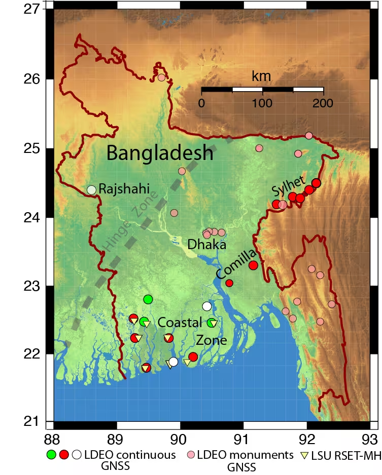
Of 16 stations running in the country, only three (green) were transmitting data back to the U.S. “I have returned here once again with others to get them working again and add three new stations (white),” Steckler writes.
Steckler was joined by a team from Dhaka University to visit the sites, make repairs and install new equipment.
Map of Bangladesh showing the locations of Steckler’s GNSS sites and regions he is visiting. The green circles are working systems, the red ones need repair, and the white ones are new. The pink circles are monuments with no active system. (Image: Mike Steckler)
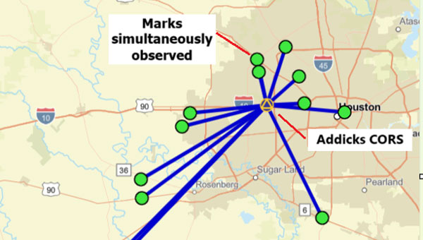
A “GNSS radial survey” is a surveying technique where a central control mark is established within an area, and vectors are measured from the central control mark to various other marks of interest surrounding the central control mark, essentially creating a “spoke-like” network design.
Plot of OPUS Projects network diagram. Hub is Addicks CORS, all marks are simultaneously observed during the session. (Photo: Dave Zilkoski)
Why not use a GNSS radial survey when establishing geodetic control networks?
Basically, you cannot directly calculate a “relative accuracy” between two marks if no observations are taken between them. That said, a direct measurement such as a GNSS vector allows error propagation between two marks. Therefore, using the “spoke-like” concept, you know the relative accuracy between the central control mark and a single mark at the end of a single spoke. Still, you don’t know the relative accuracy between marks on the different spokes.
Anyone who has used OPUS Projects or seen presentations on OPUS would think, based on the OPUS Project’s HUB processing strategy, that OPUS Projects was performing a radial survey.
When using OPUS Projects, NGS recommends that users select one CORS as a HUB while processing GNSS session data. In the example here, the Addicks CORS (ADKS) was used as the HUB in data processing. So, why is this not considered a radial survey? It may look like a GNSS radial survey but there’s a lot that goes on behind the scenes.
The bottom line is that OPUS Projects is denoted as a simultaneous (session) processor. This means the vector solution is computed from simultaneous processing of all independent vectors with mathematical correlations between all simultaneously observed vectors. OPUS Projects processing includes all independent vectors along with mathematical correlations to provide the relative connection to marks that are simultaneously observed. In the example above, when processed by OPUS Projects, all the marks occupied (indicated by the lines connecting to the Addicks CORS HUB) will have correlations computed between each other. These correlations are included in the data that is used in the least squares adjustments that are performed during the OPUS Projects workflow (NGS uses a file denoted as the gfile to document the correlations.)
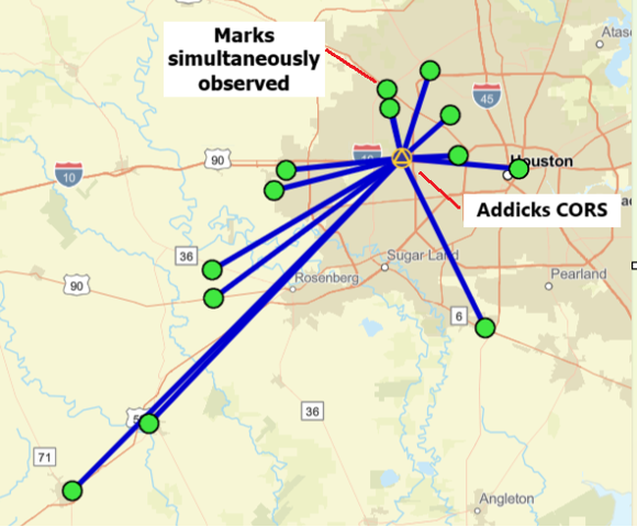
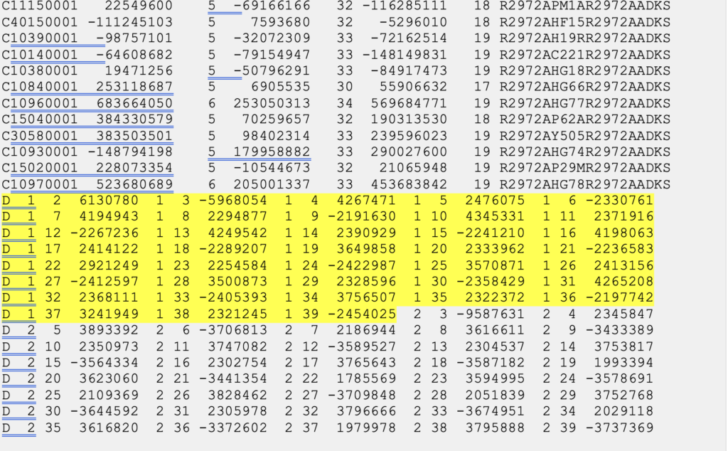
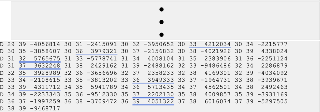
The image below provides a sample of mathematical correlations between marks simultaneously observed during the session. The gfile can be a large file when the survey includes a lot of simultaneously observed marks because there will be correlations between all marks. There were 13 marks simultaneously observed during the sample session, so the “spoke-like” diagram includes imaginary lines between every mark because of the mathematical correlations between these marks.
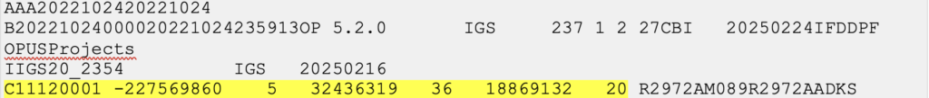
Excerpt from an output from simultaneous (session) processing. (Gfile contains baseline information with mathematical correlations.)
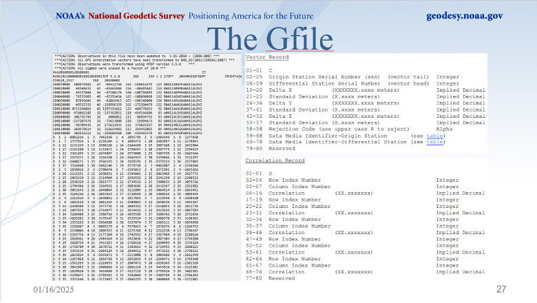
Dan’s presentation included a slide that described the file’s format. The file provides information on the vectors (delta X, delta Y, delta Z and their standard deviations) between the HUB and the individual marks, plus the mathematical correlations between all marks simultaneously observed during the session. I have highlighted a vector’s components and standard deviations and a set of mathematical correlations.
The image below, from Dan’s presentations, describes the format of NGS’s gfile.
Photo: NGS
Some software programs perform what is called sequential (baseline) processing, which involves processing one vector at a time and ignoring the mathematical correlation between baselines observed in the same session. So, what does this mean, and why is it important?
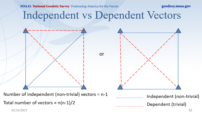
A couple of definitions are necessary to understand the concept. Independent baselines are baselines where no other baseline is a linear combination of another baseline. Linearly dependent (trivial) baselines are baselines that are linear combinations of another baseline. Basically, once you have used a particular set of data to compute a vector, you can’t use the same data to compute a different vector.
Dan did a nice job during his webinar explaining what baselines are considered trivial and what baselines are non-trivial. This is very important because if your software is a sequential (baseline) processor, you must ensure that trivial vectors are not included with the non-trivial vectors. As Dan highlights in his webinar, dependent vectors are not additional observations. But they do offer useful information if treated properly.
Photo: NGS
There was a 1992 study performed by Michael Craymer and Norm Beck, “Session Versus Baseline GPS Processing,” that explained the differences between sequential baseline processing and simultaneous (session) processing, and what the user needed to do to use sequential baseline processing. Basically, when all the trivial vectors are added to the adjustment, they are treated like additional independent observations, resulting in an inflating degree of freedom and overly optimistic error estimates. If all possible vectors are processed, then resulting coordinates may essentially be the same as in simultaneous (session) processing, but statistics will be overly optimistic and misleading. The 1992 paper does state that the two different processing techniques can produce the same results.
“It is shown that using all possible baseline solutions (with the covariance matrix scaled by n/2, where n is the number of simultaneously observing receivers) is mathematically equivalent to session processing with all correlations only under certain conditions. This equivalence is verified empirically using simulated and real data. However, the conditions under which this equivalence holds are difficult to achieve in practice.”
Users who process data using a sequential processor should read the 1992 study by Craymer and Beck to understand the conditions under which the two processes generate the same results.
I would encourage all individuals that process GNSS data, regardless of which software you use, to download the NGS OPUS User Forum webinar. NGS also has a website that provides training material on the use of OPUS Projects. The more you know about the software you use, the better you will be prepared to address issues associated with your survey results.
Trimble and Kyivstar, Ukraine’s largest telecommunications company, have partnered to install a new Continuously Operating Reference Station (CORS) network to provide GNSS correction services across the country.
Available to users as an annual subscription service, the new network will be built using Trimble’s hardware and software positioning technology. This technology provides users with reliable high-accuracy real time or post-processed GNSS corrections data for agriculture, construction, geospatial, Internet of Things (IoT) and other commercial operations.
The network will be installed on Kyivstar’s communication towers and will use Trimble Alloy reference receivers and Trimble Zephyr model 3 antennas.
Trimble Alloy offers current and near-future constellation GNSS tracking and absolute positioning capabilities. The Zephyr 3 antenna’s capabilities provide optimal functionality in permanent installations. The network will also leverage the Trimble Pivot Platform software, a solution that manages CORS stations and generates accurate GNSS corrections to provide the network operator and end users with a reliable, seamless and efficient workflow.
The first phase of the installation will include 41 communication towers and is expected to be completed by the end of 2023. The second phase will consist of 150 additional towers and is expected to be completed in 2024. Subscriptions to the service will be available through Kyivstar.
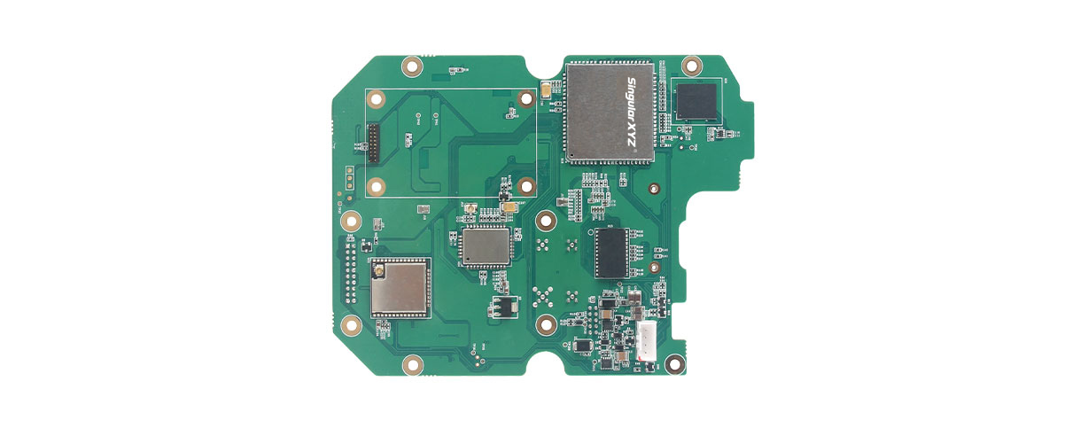
SingularXYZ, a manufacturer of GNSS technology, has launched its DK100 development kit. This multi-functional kit has selectable single-antenna and dual-antenna modules, full constellation tracking and centimeter-level positioning.
The DK100 development kit is a ready-to-use kit designed to simplify integration efforts and increase compatibility with a variety of applications. The kit reserves standard adapter board interfaces to connect different GNSS modules and radio modules for a variety of needs.
The development kit features a 4G module, Wi-Fi, Bluetooth, and Ethernet modules as well as status indicators on a single PCBA.
The DK100 development kit comes with its own web page for configuration. With Ethernet and Wi-Fi access, users can monitor device status and configure working mode and data transmission settings on the page.
The centimeter-level DK100 kit can be integrated in a range of horizontal and vertical applications, such as construction using CORS networks, precision agriculture, construction machinery, smart navigation, monitoring, robotics, unmanned systems and more.
ComNav Technology now provides a GNSS high-precision positioning solution for navigation and positioning of autonomous lawn mowers. Environmentally friendly and intelligent robotic lawn mowers are growing more popular, making the mowing task easier, safer and more convenient.
R&D background
It is difficult to develop autonomous lawn mowers because they obtain navigation information by means of visual and acoustic sensors, usually through embedded cables in the working area and detection through eddy current sensors. The shortcomings are obvious: before the mower starts, it must be set up with cables and other equipment. Cable requirements differ in various countries, and cable laying can be complicated, wasting resources and money.
With these difficulties in mind, ComNav applied its K8 series of GNSS high-precision modules to lawn mowers to break through the application limit. It solved this accuracy problem to make the lawn mower achieve centimeter-level driving according to the setup path in an open field. With ComNav’s other technologies — quantum algorithm and LAI, HighLock, PPP, RTK-KEEP — the law mowers continues to operate under trees, around corners or in other obscured areas.
Introduction of ComNav’s solution
With the K8 series module, ComNav facilitates the lawn mower’s fieldwork with position data provided by GPS, GLONASS, Galileo, Beidou, QZSS, IRNSS and SBAS.
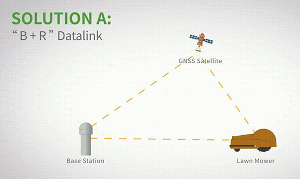
The high-precision positioning system for lawn mowers consists of a base station and a rover station. Three solutions are recommended for the terminal to obtain differential data from the base station.
Base and rover datalink. A base station acquires differential data through a datalink and provides corrections to the rover. The rover station — comprising the parts installed on the lawn mower, including the GNSS antenna, the GNSS high-precision module, datalink and UHF antenna — enables centimeter-level positioning and navigation.
Image: ComNav
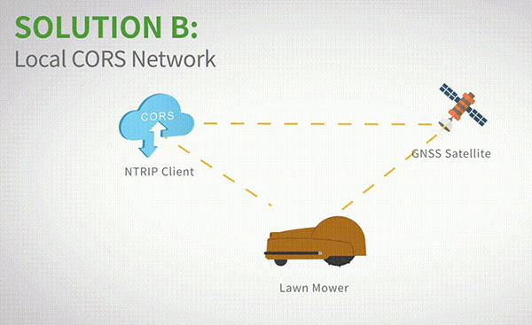
Local CORS network. Utilizing existed local CORS, the rover station obtains differential data from the CORS service, enabling the lawn mower to achieve positioning and navigation accuracy on a centimeter level.
Image: ComNav
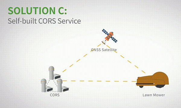
Self-built CORS network. Base stations can be placed anywhere based on requirements. Doing so eliminates the worry about prevailing conditions and makes high-precision positioning and navigation of lawn mowers possible.
Image: ComNav
Technology Features
LAI technology. ComNav’s patented low-power anti-interference (LAI) technology provides a jamming-to-signal ratio of up to 50 dB. Power consumption is only 0.1 W when turned on. By quickly detecting and eliminating interference with simple settings, LAI technology can reduce failure time and ensure safe operation. The technology can generate a spectrum diagram of interference sources, enabling identification of interference types and potential interference sources.
Quantum algorithm. ComNav’s quantum algorithm has sophisticated technology for detecting and repairing cycle slips. It uses full-constellation and full-frequency tracking capabilities along with multi-frequency combination, model and parameter estimation. Quantum is able to eliminate errors caused by the ionosphere, the troposphere and multipath in seconds. As a result, the initialization time of real-time kinematic (RTK) is greatly shortened and precision and reliability are improved. Meanwhile, the extra-long baseline calculation capability expands the operation range.
RTK-KEEP technology. By estimating model and parameter values, RTK-KEEP Technology can reduce errors caused by satellite orbit, clock difference, ionosphere and troposphere when the base station’s data is lost. Centimeter-level accuracy can be kept for more than 10 minutes, greatly improving the availability of RTK.
Benefits of ComNav’s Solution
ComNav’s solution allows the lawn mower to achieve centimeter-level positioning and reduce mowing repetitions. It helps the lawnmower to operate safely and reliably in the corners, under trees, or in other places where satellite signals are weak or lost. With its strong anti-interference capabilities, the lawn mower can maintain continuous and effective positioning in complex environments, meeting the needs of a variety of applications.
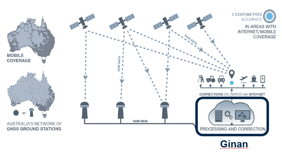
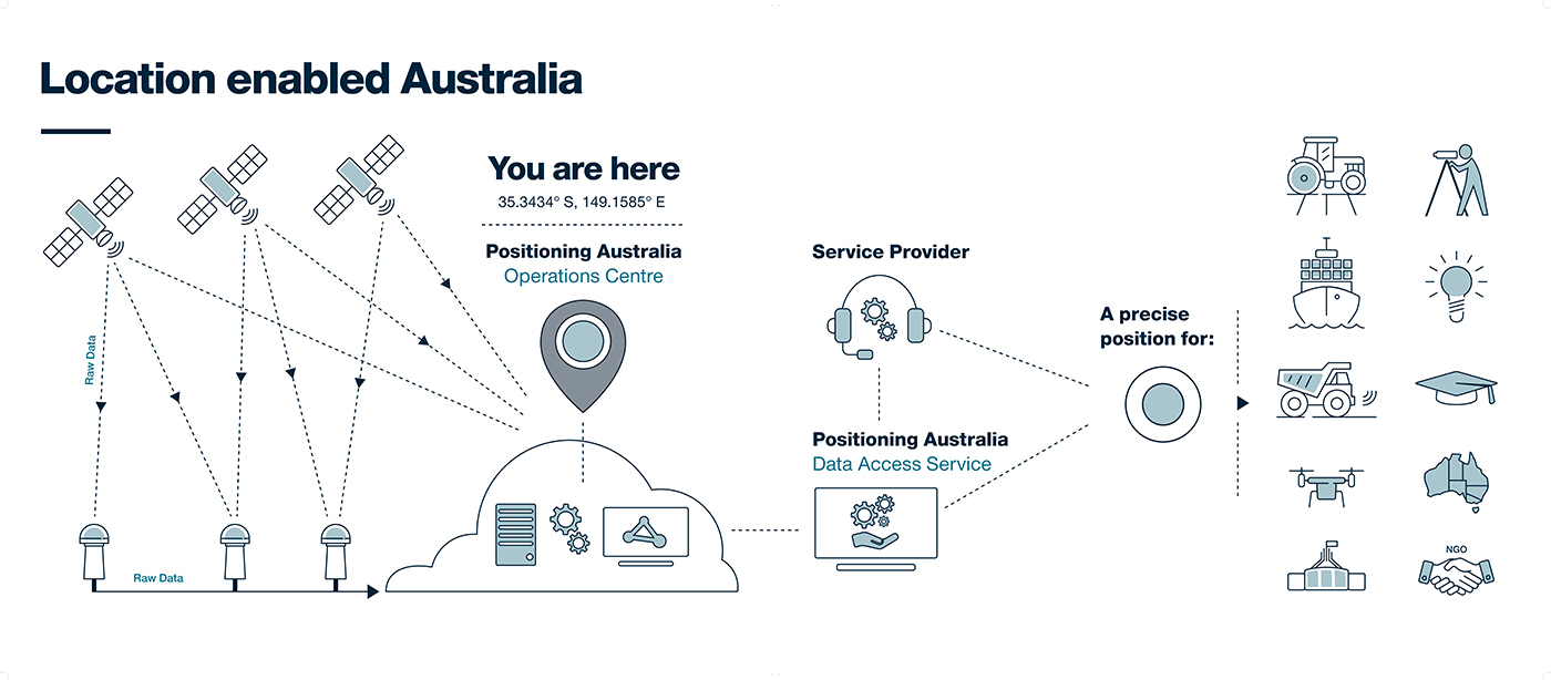
NPIC is key to a location-enabled Australia. (Image: Geoscience Australia)
Geoscience Australia is undertaking an assessment of the economic impact of the National Positioning Infrastructure Capability (NPIC) program.
The program provides free and open access to multi-GNSS observation streams from Australia’s network of continuously operating reference stations (CORS).
Users can connect to these data and product streams directly from Geoscience Australia or via a commercial positioning-service provider. The CORS network has been designed to support a national positioning capability that provides better than 5-cm accurate positioning solutions in areas with access to mobile-phone coverage (delivery via the internet).
Geoscience Australia has engaged ACIL Allen to conduct a web-based survey for stakeholders with interest in this program to assist with data gathering for the economic assessment.
The survey takes 15 to 20 minutes to complete. There is an additional optional component for service providers that may take an additional 15 minutes.
It can be completed in stages, if necessary, with a facility to save responses. It will remain open until June 28 (extended from May 25).
Questions can be directed to Alan Smart (project director) at 0404 822 312 or Nanumi Starke (ACIL Allen) at 0466 636 345.
ComNav’s high-accuracy PileMaster sped construction of the Aarah Resort in the Maldives. Photo: LANKA Foundation and Piling Services Pvt. Ltd.
The construction of the Aarah Resort in the Maldives involved building 64 luxury water villas and 12 beach buildings on a shallow-water area with about 1,400 piles. LANKA Foundation and Piling Services Pvt. Ltd. was able to complete the piling project in only 32 days by using a high-accuracy piling solution from ComNav Technology Ltd.
The traditional piling approach requires many surveyors to stake out the positions of the piles underwater in advance. Not only is this process labor-intensive, it also creates a real-time problem: even if the coordinates are measured accurately by lofting, the primary coordinate markers are soon out of position due to the movement of the piling machines. The stakeout’s accuracy is also threatened by strong waves, ocean currents and coral reefs. Furthermore, in the subsequent piling process, the piling accuracy is reduced due to artificial aiming. During the whole process, surveyors must work in the water and fix the piles at short range, which is dangerous. For these reasons, the traditional piling approach is a low-efficiency, high-cost and high-risk operation.
Photo: Google Earth
ComNav’s professional positioning solution for high-accuracy piling provides a 9-inch high-resolution tablet with an integrated GNSS receiver, a T300 GNSS receiver as the base station, and two AT340 antennas with magnetic mounts combined with PileMaster software. Its integrated GNSS receiver tracks GPS, GLONASS and BeiDou signals, enabling the system to work even in challenging environments. The system can acquire real-time kinematic (RTK) corrections via an internal UHF transceiver from the T300 receiver or connect to a local continuously operating reference station (CORS). Moreover, PileMaster is designed with an intuitive interface with clear element-management capability, supporting import of up to 10,000 points from Excel, TXT and CAD formats to meet the specific demands of a high-accuracy piling project.
Compared to the traditional piling method, ComNav’s intelligent control system for piling is an all-weather, high-accuracy solution with the additional advantages of being widely compatible and easy to manage. Through software system control and real-time processing and display, it can greatly reduce the number of surveyors required on-site. The system can guide users to the location, shorten the construction period, save construction costs, and enable intelligent visualization and monitoring to ensure high-precision construction work.
After a first successful application in 2017, Foresight Surveyors Pvt. Ltd, ComNav’s local partner in the Maldives, used the solution in many projects, including construction of the Kunaavashi Resort & Spa in 2018 and the Kuda Villingili, Dhigufaru Island and Maniya Faru resorts in 2019.
The largest seaportS on America’s West Coast are the Ports of Long Beach and Los Angeles, located next to each other in San Pedro, California. (Photo: Art Wager/E+/Getty Images)
The Port of Long Beach, California, is moving up and down because it sits on fault blocks that move like pistons due to subsidence caused by oil extraction. To accurately keep track of these movements, the port’s surveyors use GNSS receivers that receive corrections from continuously operating reference stations (CORS) operated by the port and by the City of Long Beach.
CORS corrections compensate for errors inherent in GPS — clock drift, orbit errors, signal errors and atmospheric errors.
Monitoring Subsidence. A monitoring receiver is placed on each fault block’s anticline, said Kim Holtz, director of survey for the Port of Long Beach. Her agency has 15 stations, along the coast, and a couple in the Port of Los Angeles. They were installed originally in the 1990s, using Trimble 5700s. “We are constantly monitoring to make sure that the fault blocks are not moving too much and that they are not moving horizontally other than all together, as the plates move to the north,” Holtz said.
Also, the Long Beach Energy Resources Department has 14 Trimble R9 base stations. While Energy Resources uses the equipment to get precise elevation differences and measure subsidence for movement of more than 0.025 feet, the port uses them mainly for horizontal measurements for construction.
The port’s hydrographic survey boat, the pilot boats, and the dig alert crew that marks utilities for construction operations also use the receivers to tie into the CORS network. “The stations are about eight or nine years old and Energy Resources is getting ready to replace all of them with Trimble Alloy GNSS reference receivers, over a three-year period,” Holtz said.
Digital Level Run. The port normally performs a digital level run from a tidal wave base station in San Pedro, which dates to the 1920s. “We run a level run from that and, at the same time, Energy Resources does a GPS subsidence survey, where they get elevation,” Holtz explained. “Last year, we combined the two surveys, to compare the data and see whether we could use some of their GPS data for our level run. It was very promising. We are going to do it again in November.
“Then, if it works, we will cut our level run, which normally takes two months, down to about a week or two. We will just come off of the main benchmarks on which Energy Resources puts a GPS elevation.”
To keep the elevations tight, more than 10 years ago Long Beach created its own geoid. “It is a hybrid of GEOID12B, and we’ve updated it a couple of times,” Holtz said.
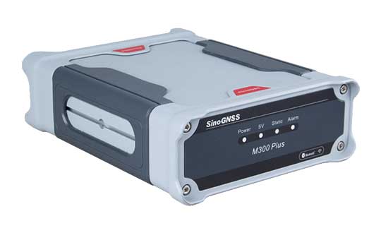
ComNav Technology has released the M300 Plus GNSS receiver to the international market.
The M300 Plus is designed to supplement the company’s M300 Pro, which is aimed at clients who need a more economical version for their CORS networks. The M300 Plus not only can be used as a CORS receiver, but is a good choice for monitoring projects and other applications.
With ComNav Technology’s new-generation GNSS engine, the M300 Plus can track all current and future constellations. By using a powerful, adaptive detecting and canceling technology, the M300Plus provides enhanced anti-jamming capability, which is critical for a reference station providing reliable GNSS data.
Photo: ComNav
The M300 Plus’ powerful built-in web server provides full remote control of the receiver configuration, status checking, firmware update and data download. It supports multiple independent data transfer through TCP/UDP/Ntrip protocol in RTCM, ComNav binary, NMEA and BINEX data formats, combined with Email Alert and FTP push, which improves the efficiency and profitability of businesses.
In addition to its standard Ethernet port for data transmitting, the M300 Plus GNSS receiver also fully implements a 4G module as an internet backup, which enhances the stability of data connections.
M300 Plus is now available through ComNav Technology authorized local distributors or ComNav Technology directly.