New Task Force to Develop Recommendations by Nov. 20
WASHINGTON — U.S. Transportation Secretary Anthony Foxx and FAA Administrator Michael Huerta today announced the creation of a task force to develop recommendations for a registration process for Unmanned Aircraft Systems (UAS).
The task force will be composed of 25 to 30 diverse representatives from the UAS and manned aviation industries, the federal government and other stakeholders. The group will advise the department on which aircraft should be exempt from registration due to a low safety risk, including toys and certain other small UAS. The task force also will explore options for a streamlined system that would make registration less burdensome for commercial UAS operators.
The task force may make additional safety recommendations as it deems appropriate. Secretary Foxx directed the group to deliver its report by Nov. 20.
“Registering unmanned aircraft will help build a culture of accountability and responsibility, especially with new users who have no experience operating in the U.S. aviation system,” Foxx said. “It will help protect public safety in the air and on the ground.”
Every day, the FAA receives reports of potentially unsafe UAS operations. Pilot sightings of UAS doubled between 2014 and 2015. The reports ranged from incidents at major sporting events and flights near manned aircraft, to interference with wildfire operations.
“These reports signal a troubling trend,” Huerta said. “Registration will help make sure that operators know the rules and remain accountable to the public for flying their unmanned aircraft responsibly. When they don’t fly safely, they’ll know there will be consequences.”
While the task force does its work, the FAA will continue its aggressive education and outreach efforts, including the Know Before You Fly campaign and No Drone Zone initiatives with the nation’s busiest airports. The agency also will continue to take strong enforcement action against egregious violators. At the same time, it will continue working with stakeholders to improve safety to ensure further integration and innovation in this promising segment of aviation.
Secretary Foxx was joined by representatives from the following stakeholder groups:
UPDATE (9/10/15): A public workshop will be held in Washington, D.C., on Oct. 2 to provide an opportunity to discuss the draft test plan and address questions before the close of the public comment period. The workshop will be held in the RTCA NBAA/Colson Room, 1150 18th St. NW, Suite 910, Washington, D.C., 20036. Click here to register for the workshop.
The U.S. Department of Transportation today published a Federal Register Notice seeking public comment on a draft test plan for the GPS Adjacent Band Compatibility Assessment effort. The plan aims to obtain interference tolerance masks for GNSS receivers in the L1 radiofrequency band (1559-1610 MHz).
The objective of the test is to collect data to determine Interference Tolerance Masks (ITM) for categories of GPS and GNSS receivers processing signals in the 1559-1610 MHz Radionavigation Satellite Service (RNSS) frequency band, as well as receivers that process Mobile Satellite Service (MSS) signals to receive differential corrections.
Demand for commercial spectrum to support broadband wireless communications — in particular, LightSquared — has led the government to consider repurposing various radio frequencies, including the satellite communications bands next to GPS. The ITMs will be used to assess the adjacent band interference power levels that can be tolerated by GNSS receivers processing desired signals in the RNSS band.
The document outlines the requirements, the overall test plan, and the associated output data needed to successfully perform this component of the GPS Adjacent Band Compatibility assessment.
The plan can be downloaded here. Deadline for comments is Oct. 9.
In December 2012, the DOT developed its GPS Adjacent Band Compatibility Assessment Plan that identifies the processes to:
Derive adjacent-band transmitter power limit criteria for assumed new applications necessary to ensure continued operation of GPS services, and
determine similar levels for future GPS receivers utilizing modernized GPS and interoperable GNSS signals.
The DOT has previously held three public workshops to discuss the Adjacent Band Compatibility Assessment.
Let us not exaggerate — nor prematurely announce — the death of a subsystem. However, the demise of the U.S. Nationwide Differential GPS (NDGPS) network can be confidently foretold. Although a Federal Register notice dated Aug. 18 merely seeks public comment on plans to shut down a large portion of NDGPS, the handwriting is on the wall. Once having writ, the hand of fate moves on.
We should neither lament nor applaud. NDGPS, like many other technologies, has seen its time come and go, while competitors have arisen to perform its role and take its place. Such is evolution in the industrial world as well as in the biological kingdoms.
In 2016, three quarters of the currently operating NDGPS reference stations will be taken down and decommissioned. That’s not what the federal notice states, but that’s what it effectively says. The document’s comment period ends on Nov. 16. It is difficult to conceive of a public outcry that might reverse the intended course of the U.S. Coast Guard, Department of Transportation and Army Corps of Engineers.
The NDGPS network had its birth in the 1980s, as a tool to provide real-time positioning accuracy for harbor entrances and coastal navigation. Inland components were added over the years to improve river navigation, NDGPS use in precision agriculture began to grow, and a role in railroad positive train control (PTC) was much discussed. But all these efforts could not gather enough momentum to firmly establish the network’s viability. Meanwhile, satellite-based differential services from both commercial providers and the U.S. government’s own Wide Area Augmentation System (WAAS), and a network of continuously operating reference stations (CORS) from the National Geodetic Survey continually nibbled away at NDGPS’s potential customer base. Consequently, industry fielded a meager range of radiobeacon DGPS receivers.
The real death blow came in 2013, when the Federal Railroad Administration (FRA) eliminated an NDGPS requirement from its PTC program. The railroads, never a nimble industry nor one receiving the governmental support it enjoys in other countries, had by that time become the last hope of NDGPS. Ag users had already for the most part moved over to WAAS and commercial SBAS providers. Marine users did not by themselves form a sufficiently large constituency, and even they were not fully equipped nor wholesale adopters of the system.
The story of Loran bears some similarities to NDGPS, but Loran now enjoys a resurgence that NDGPS will never see. It is destined for the technological graveyard. There is an ecosystem of positioning, navigation and timing (PNT) tools and applications. Operating in a free market, with some measure of governments’ interference and manipulation, it has its own patterns of natural selection. We will continue to see the rise and fall of species. NDGPS has now been branded a dinosaur. It will be interesting to see how other technologies, competing for the same finite range of resources, will interact, thrive, or decline.
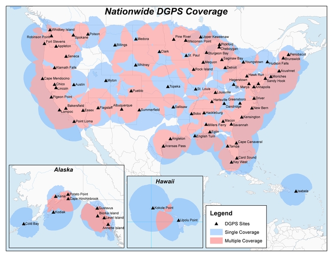
Twenty-two NDGPS sites that serve coastal areas would remain operational under the proposal.
An Aug. 18 Federal Register notice proposes shutting down the Nationwide Differential Global Positioning System (NDGPS) in January 2016 because of a decline in its use, except for sites in coastal areas.
The notice, issued by the U.S. Coast Guard (USCG), Transportation Department (DOT) and Corps of Engineers (USACE), reads:
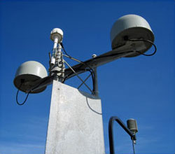
The Nationwide Differential Global Positioning System (NDGPS) service augments GPS by providing increased accuracy and integrity using land-based reference stations to transmit correction messages over radiobeacon frequencies. The service was implemented through agreements between multiple federal agencies including the USCG, DOT, and Army Corps of Engineers, as well as several states and scientific organizations, all cooperating to provide the combined national DGPS utility.
However, a number of factors have contributed to declining use of NDGPS and, based on an assessment by the Department of Homeland Security, DOT and USACE. DHS, DOT and USACE are proposing to shut down and decommission 62 DGPS sites, which will leave 22 operational sites available to users in coastal areas.
A DGPS reference station antenna.
Contributing factors cited in the decision are:
USCG changes in policy to allow aids to navigation (ATON) to be positioned with a GPS receiver using Receiver Autonomous Integrity Monitoring (RAIM), which assesses the integrity of a GPS signal within the receiver;
increased use of Wide Area Augmentation System (WAAS) in commercial maritime applications, which uses ground-based reference stations and satellite communications to improve accuracy;
limited availability of consumer-grade NDGPS receivers;
no NDGPS mandatory carriage requirement on any vessel within U.S. territorial waters;
the DOT Federal Railroad Administration’s determination that NDGPS is not a requirement for the successful implementation of Positive Train Control (PTC), which provides the railway system the capability to positively enforce movement authorities along railroad systems.
In April 2013, announced that DHS and DOT were in the process of analyzing the need for NDGPS. “The response to the 2013 notice was limited, but the responses received were well informed on the NDGPS system, its use, and current and potential applications,” the notice reads. “While a limited number of responders found the broadcast of corrections to be beneficial, no respondents reported the discontinuance of DGPS broadcast to be detrimental or harmful. Ship pilots in particular noted that DGPS can be critical in confined waterways for precise ship-handling maneuvers.”
Public comments on the proposed shutdown and decommissioning of 62 DGPS sites are being accepted until Nov. 16. Termination of the NDGPS broadcast at these sites is planned to occur on Jan. 15, 2016.
Full details on how to submit public comments can be found on the Federal Register page.
The U.S. Department of Transportation will host a third workshop to continue discussions of the GPS Adjacent Band Compatibility Assessment on March 12.
The workshop will focus on the following topics:
Identification of GPS and GNSS receivers to be considered for testing that are representative of the current categories of user applications
Discussion of a GPS/GNSS receiver test plan.
Anyone interested in presenting on either or both of the above topics should contact Stephen Mackey by March 2.
The workshop will be held 8:30 a.m.-3:30 p.m. PDT at Aerospace Corporation, 2310 E. El Segundo Blvd., El Segundo, California.
Galileo IOV Bird Mute; New Draft ICD; CS Proved; Late August Launch
Orbiting in silence since an onboard power mishap on May 27, troubled E20 emitted cheeps from space on August 6, 7, and 8, broadcasting on the L1 frequency. Nothing has been heard since.
Meanwhile, the European Commission (EC) published a new draft version of the Galileo Open Service Signal in Space Interface Control Document (OS SIS ICD), issue 1, revision 2, on June 30. It is available for download and comment, the latter period extending to September 22. The EC’s open public consultation process seeks to ensure that any further development of the Galileo OS SIS ICD takes into account the views of key GNSS stakeholders. An online form for submitting comments is available.
Galileo E20, also known as GSAT0104, the fourth in-orbit validation (IOV) satellite, has been set “unavailable until further notice” according to the European GNSS Service Centre because of a sudden, unexpected loss of power on May 27.
Based on a selected set of IGS MGEX stations and all CONGO stations, the first signals were tracked at AREG, AUT0, LLAG, and UNB3 at 23:13:00. No E5 signals and no navigation messages are currently transmitted. Some JAVAD GNSS receivers report from time to time false E5a locks with zero or extremely small C/N0.
Galileo’s Early Proof of Concept (EPOC) team has successfully tracked the encrypted Galileo E6-B and E6-C signals broadcast by Galileo satellites. As a result, the Commercial Service loop has been closed using both encrypted and non-encrypted signals.
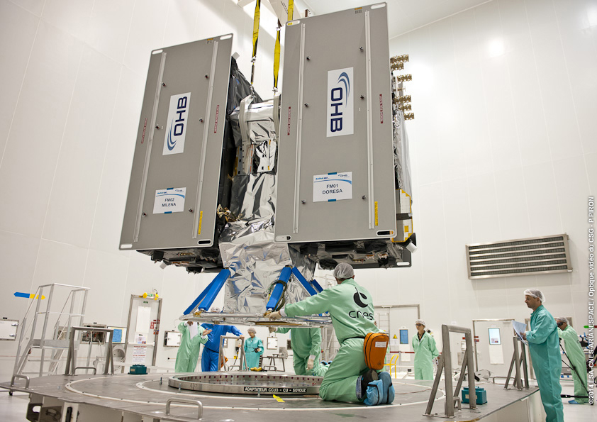
The completed dispenser unit is ready to be transferred from the S5 payload preparation facility for its integration atop Soyuz’ Fregat upper stage.
During a 10-day testing period, receivers in Tres Cantos, Spain and Poing, Germany, showed the successful tracking and data demodulation of the encrypted signals from the available Galileo satellites, with periods where all satellites transmitting E6 encrypted signals were tracked simultaneously. The tests verified the Galileo Commercial Service (CS) signal’s encryption functionalities, with the data received containing authentication and high accuracy information previously generated outside the Galileo system. This is an essential feature to ensuring Galileo’s high accuracy and authentication services.
The Galileo Commercial Service will deliver a range of added-value features, including positioning accurate to decimeter level and an authentication element. The Galileo CS demonstrator began its proof of concept earlier this year, with early service expected to start in 2016.
Once operational, the CS will provide access to two additional encrypted signals on the E6 band, delivering a higher data throughput rate and increased accuracy. The tests are the result of a collective effort involving teams and projects of AALECS (Authentication and Accurate Location Experimentation with the Commercial Service), supported by the European Commission, the GSA, the European Space Agency (ESA), and the Galileo operator Spaceopal.
The AALECS project is building a platform to connect to the European GNSS Service Centre (GSC) and transmit real-time CS data through the Galileo satellites. This platform will be operational by 2015 and will demonstrate the real performance of future high-accuracy and authentication services of Galileo prior to early service availability.
The European Commission launched AALECS in January 2014, and it was awarded to a consortium led by GMV including CGI, Qascom, IFEN, Veripos, and KU Leuven.
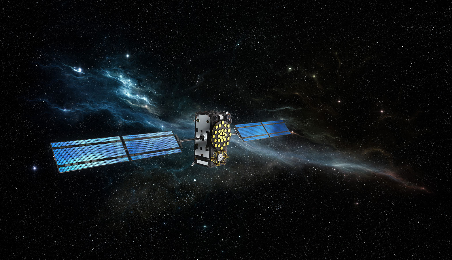
New Launch. At press time, the next Galileo satellites were set to launch on August 21, ushering in the system deployment phase and paving the way for the start of initial services. Galileo SATs 5 and 6 were scheduled to lift off from Europe’s Spaceport in French Guiana on top of a Soyuz rocket. They are expected to become operational, after initial in-orbit testing, in autumn.
The two satellites will join the four Galileo in-orbit validation satellites already in space. Launched in pairs in October 2011 and October 2012, these four — the minimum required to obtain a position fix — demonstrated and validated the system’s space and ground segments.
SATs 7 and 8 are scheduled to follow by end of year 2014. Then the constellation will be gradually deployed with six to eight satellites launched per year, along with addition of remaining elements of the ground network.
Adjacent-Band Compatibility Workshop Set for D.C.
The U.S. Department of Transportation is holding a “GPS Adjacent Band Compatibility Assessment Workshop” on September 18, 10 a.m.–5 p.m. Eastern Daylight Time. Registration for the workshop is required, and closes September 4. The general public can either attend in person or via WebEx.
The workshop is being held to discuss implementation of a GPS Adjacent Band Compatibility Assessment. Discussion will focus on the various implementation steps of the assessment, including development of GPS receiver use cases, identification of representative GPS receivers, and development of a test and analysis program. “In particular, emphasis will be placed on the information needed from GPS receiver and antenna manufacturers, and the logistics of procuring and handling that information to safeguard manufacturer proprietary data,” according to the Federal Register.
The sponsoring agency is the Office of the Assistant Secretary for Research and Technology, Department of Transportation.
The meeting will be held at the U.S. Department of Transportation, John A. Volpe National Transportation Systems Center, 55 Broadway, Cambridge, MA 02142. ID is required to enter the building. For details, see the Federal Register notice.
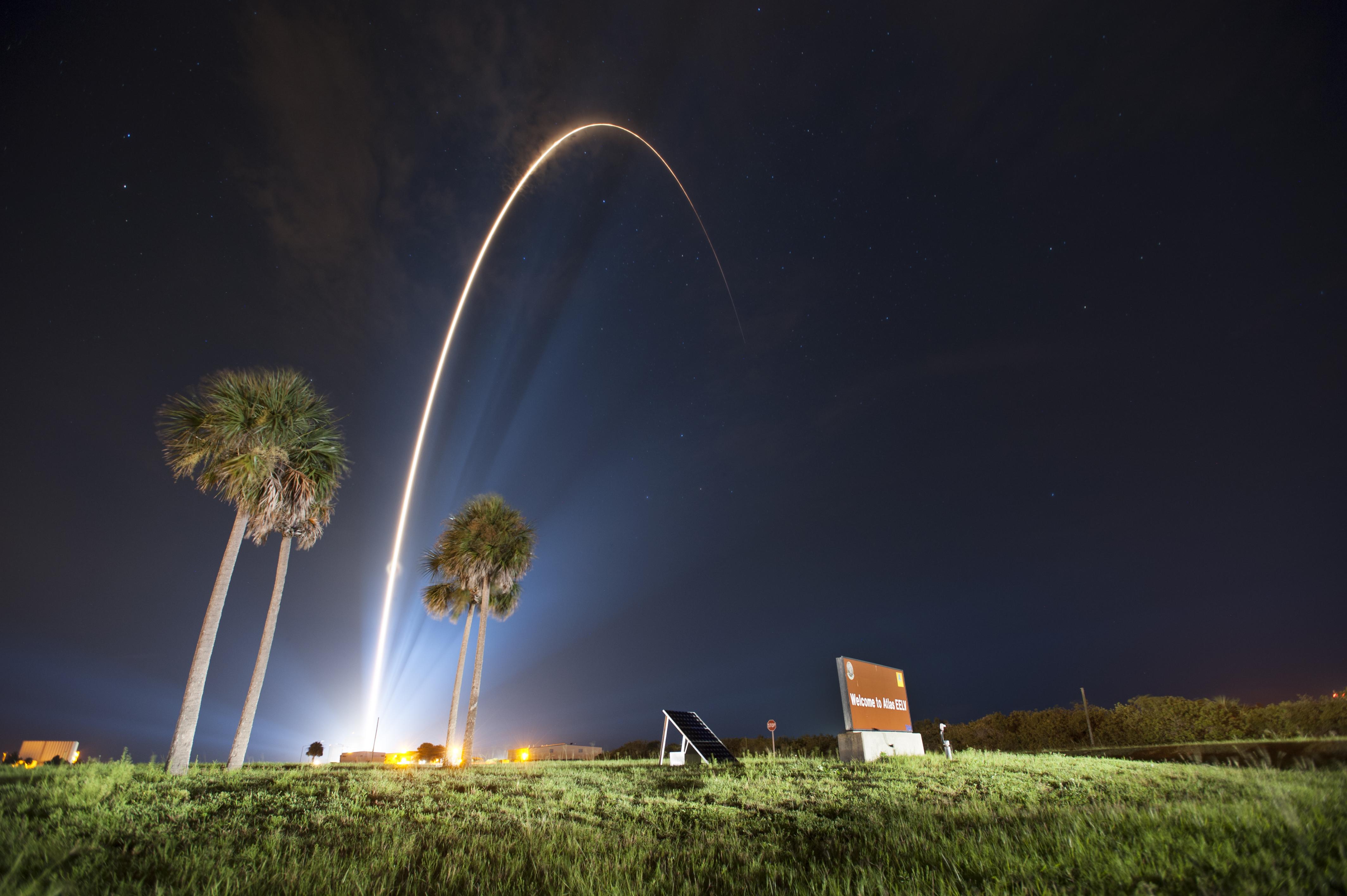
GPS IIF-7 Successfully Launched
Last USAF Launch to Rely on Radar as GPS Tracking Takes Over
A United Launch Alliance (ULA) Atlas V rocket carrying the seventh GPS IIF satellite for the U.S. Air Force launched at 11:23 p.m. EDT Friday, August 1 (03:23 UTC, August 2), from Space Launch Complex-41 at Cape Canaveral, Florida.The Boeing-built satellite has sent the signals to controllers that confirm it is currently operating properly within the constellation.
Boeing and the Air Force will complete the full on-orbit checkout of the satellite in August. The GPS IIFs offer improved signal accuracy, better anti-jamming capability, longer design life and the new civilian L5 signal.
“We are providing our Air Force partner and GPS users with a steady supply of advanced GPS IIFs,” said Craig Cooning, president of Boeing Network & Space Systems. “Our robust launch tempo requires vigilance and attention to detail, and mission success is our top priority. We continue to partner with the Air Force and ULA to effectively execute the launch schedule.”
GPS IIF-7 is the seventh of 12 such satellites Boeing has built for the U.S. Air Force, and the third on-orbit delivery this year. GPS IIF-8, slated for launch during the fourth quarter, arrived at Cape Canaveral on July 16 to undergo final launch preparations. GPS IIF-7 will join a worldwide timing and navigation system utilizing 24 satellites in six different planes, with a minimum of four satellites per plane positioned in orbit approximately 11,000 miles above the Earth’s surface.
“Congratulations to the U.S. Air Force and all of our mission partners on the successful launch of the Atlas V carrying the GPS IIF-7 satellite,” said Jim Sponnick, ULA vice president, Atlas and Delta Programs. “ULA launch vehicles have delivered all of the current generation of GPS satellites, which are providing ever-improving capabilities for users around the world.”
This mission was launched aboard an Atlas V Evolved Expendable Launch Vehicle (EELV) 401 configuration vehicle, which includes a 4-meter-diameter payload fairing. The Atlas booster for this mission was powered by the RD AMROSS RD-180 engine, and the Centaur upper stage was powered by a single Aerojet Rocketdyne RL10A engine.
The EELV program was established by the United States Air Force to provide assured access to space for Department of Defense and other government payloads. The commercially developed EELV program supports the full range of government mission requirements, while delivering on schedule and providing significant cost savings over the heritage launch systems.
C-Band Radar. The launch August 1 marked the final time the Air Force is expected to rely on C-band radars to track rockets immediately following liftoff.
Future Air Force launches, both from the Cape and from Vandenberg Air Force Base in California, will rely on GPS signals for post-liftoff tracking, service officials said. The Air Force and its primary launch services provider, ULA, have been working for years on the capability, which features rocket-mounted GPS receivers that transmit position-location data to controllers on the ground.
“It’s something that’s been a long time coming,” Walt Lauderdale, GPS IIF-7 mission director, said during a July 25 conference call with reporters. The new technique has been tested and proven at both at Cape Canaveral and Vandenberg over the last few years, he said.
The U.S. Department of Transportation is holding a “GPS Adjacent Band Compatibility Assessment Workshop” on September 18, 10 a.m.–5 p.m. Eastern Daylight Time. Registration for the workshop is required, and closes September 4. The general public can either attend in person or via WebEx.
The workshop is being held to discuss implementation of a GPS Adjacent Band Compatibility Assessment. Discussion will focus on the various implementation steps of the assessment, including development of GPS receiver use cases, identification of representative GPS receivers, and development of a test and analysis program. “In particular, emphasis will be placed on the information needed from GPS receiver and antenna manufacturers, and the logistics of procuring and handling that information to safeguard manufacturer proprietary data,” according to the Federal Register.
The sponsoring agency is the Office of the Assistant Secretary for Research and Technology, Department of Transportation.
• Name
• Organization
• Telephone number
• Mailing and email addresses
• Attendance method (WebEx or on site)
• Country of citizenship
The meeting will be held at the U.S. Department of Transportation, John A. Volpe National Transportation Systems Center, 55 Broadway, Cambridge, MA 02142. ID is required to enter the building.
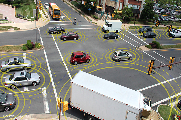
Connected vehicles can help to mitigate crashes on busy urban streets.
The U.S. Department of Transportation’s (DOT) National Highway Traffic Safety Administration (NHTSA) announced today that it will begin taking steps to enable vehicle-to-vehicle (V2V) communication technology for light vehicles. This technology would improve safety by allowing vehicles to “talk” to each other and ultimately avoid many crashes altogether by exchanging basic safety data, such as speed and position, ten times per second, the agency said.
“Vehicle-to-vehicle technology represents the next generation of auto safety improvements, building on the life-saving achievements we’ve already seen with safety belts and air bags,” said U.S. Transportation Secretary Anthony Foxx. “By helping drivers avoid crashes, this technology will play a key role in improving the way people get where they need to go while ensuring that the U.S. remains the leader in the global automotive industry.”
DOT research indicates that safety applications using V2V technology can address a large majority of crashes involving two or more motor vehicles. With safety data such as speed and location flowing from nearby vehicles, vehicles can identify risks and provide drivers with warnings to avoid other vehicles in common crash types such as rear-end, lane change, and intersection crashes. These safety applications have been demonstrated with everyday drivers under both real-world and controlled test conditions.
The safety applications being developed provide warnings to drivers so that they can prevent imminent collisions, but do not automatically operate any vehicle systems, such as braking or steering. NHTSA is also considering future actions on active safety technologies that rely on on-board sensors. Those technologies are eventually expected to blend with the V2V technology. NHTSA issued an Interim Statement of Policy in 2013 explaining its approach to these various streams of innovation. In addition to enhancing safety, these future applications and technologies could help drivers to conserve fuel and save time.
V2V technology does not involve exchanging or recording personal information or tracking vehicle movements. The information sent between vehicles does not identify those vehicles, but merely contains basic safety data. In fact, the system as contemplated contains several layers of security and privacy protection to ensure that vehicles can rely on messages sent from other vehicles and that a vehicle or group of vehicles would be identifiable through defined procedures only if there is a need to fix a safety problem.
In August 2012, DOT launched the Safety Pilot “model deployment” in Ann Arbor, Michigan, where nearly 3,000 vehicles were deployed in the largest-ever road test of V2V technology. DOT testing is indicating interoperability of V2V technology among products from different vehicle manufacturers and suppliers and has demonstrated that they work in real-world environments.
In driver clinics conducted by the Department prior to the model deployment, the technology showed high favorability ratings and levels of customer acceptance. Participants indicated they would like to have V2V safety features on their personal vehicle.
“V2V crash avoidance technology has game-changing potential to significantly reduce the number of crashes, injuries and deaths on our nation’s roads,” said NHTSA Acting Administrator David Friedman. “Decades from now, it’s likely we’ll look back at this time period as one in which the historical arc of transportation safety considerably changed for the better, similar to the introduction of standards for seat belts, airbags, and electronic stability control technology.”
NHTSA is now finalizing its analysis of the data gathered as part of its year-long pilot program and will publish a research report on V2V communication technology for public comment in the coming weeks. The report will include analysis of the Department’s research findings in several key areas including technical feasibility, privacy and security, and preliminary estimates on costs and safety benefits. NHTSA will then begin working on a regulatory proposal that would require V2V devices in new vehicles in a future year, consistent with applicable legal requirements, Executive Orders, and guidance. DOT believes that the signal this announcement sends to the market will significantly enhance development of this technology and pave the way for market penetration of V2V safety applications.
“We are pleased with the direction NHTSA is taking in terms of V2V technology,” said Greg Winfree, Assistant Secretary for Research and Technology. “The decision to move forward comes after years of dedicated research into the overwhelming safety benefits provided by a connected vehicle environment.”
V2V communications can provide the vehicle and driver with 360-degree situational awareness to address additional crash situations — including those, for example, in which a driver needs to decide if it is safe to pass on a two-lane road (potential head-on collision), make a left turn across the path of oncoming traffic, or in which a vehicle approaching at an intersection appears to be on a collision course. In those situations, V2V communications can detect threats hundreds of yards from other vehicles that cannot be seen, often in situations in which on-board sensors alone cannot detect the threat.
NHTSA has worked in close partnership in this research both with other DOT agencies, including the Office of the Assistant Secretary for Research and Technology and the Federal Highway Administration, and with several leading auto manufacturers and academic research institutions, who have invested significant resources into developing and testing V2V technology. The collaboration of government, industry and academia is critical to ensure V2V technology’s interoperability across vehicles.
In the wake of last month’s Expert Advice column on eLoran — “The Low Cost of Protecting America” by Dana Goward of the Resilient Navigation and Timing Foundation — come several positive comments and encouraging developments. Rather than rehearse all the arguments why we should care about this, I’ll repeat the one word that I heard most often in GNSS circles in 2013: jamming. Followed closely by: spoofing.
“I have been advocating strongly for reconsideration of the government’s domestic Loran decision for the last year or so,” writes one reader positioned on Washington’s Beltway, “and specifically working within the Department of Defense (DoD) to ensure it is aware of international developments for eLoran in the UK and South Korea, and the possibilities inherent in other former Loran chains.
“The DoD is beginning to recognize the value of eLoran as a complement to GPS, not only for international missions, but in cooperation with the departments of Transportation and Homeland Security for domestic critical infrastructure.”
Last fall, Don Jewell’s Defense PNT newsletter on the same subject drew this reply from another well-known expert:
“One of the key short-term actions is to prevent the decommissioned [Loran] sites from being sold off for subdivisions. These sites are a national treasure with unique properties: soil conductivity, water content, metal content, and more that are hugely important in siting low-frequency positioning systems. Those long-gone engineers of the 1940s and ’50s knew this and chose accordingly.”
Before last month’s issue appeared but after it had gone to press, President Obama signed the National Defense Authorization Act (NDAA) for 2014. It contained several favorable New Year’s auguries for positioners, navigators, and timers.The act evinced an acute awareness of the vulnerability of space systems to disruption. The act is also a law governing the land. Through it Congress requires the administration to, among other things, explain biennially in its “Space Protection Strategy” report exactly how, in the event space systems are disrupted, DOD and the intelligence community “plan to provide necessary national security capabilities through alternative space, airborne, or ground systems.”
Since said administration acted early in its first term to decommission Loran-C, the congressional directive is pointed.
The next big thing coming up on the GNSS international horizon takes place in Rotterdam, the Netherlands, April 15–17: the European Navigation Conference, ENC-GNSS 2014. It includes a track session on “eLoran and other Low-Frequency Systems,” and I’ll be there with pencil sharpened.
Brad Parkinson will give the ENC keynote, and he is on record as one of an august group of Institute for Defense Analyses experts who unanimously recommended that the existing Loran-C be greatly updated and modernized to eLoran. We should hear more from him on this subject amid the wharves, waterways, and docks of Europe’s largest port (world’s third busiest).
There’s barely room left to report the successful tests of Enhanced Differential Loran (eDLoran) by Dutch specialists Reelektronika: absolute accuracy of 5 meters in the North Sea and in the Rotterdam Europort harbor area.
The departing Deputy Secretary of Transportation, John Porcari, wrote a letter in the closing days of 2013 opposing the U.S. Air Force’s announced plans to begin broadcasting Civil Navigation (CNAV) message-populated L2C and L5 signals as early as April 2014. Military personnel are incensed over what they see as Porcari’s impugning, when not ignoring, the Air Force 35-year track record of broadcasting the gold standard of global navigation satellite signals — something in which Transportation has zero experience.
Porcari alludes in his December 27 letter to “non-standard engineering tools” and “non-standard operations” that he believes would come into play for early CNAV broadcast. “These have the potential to inject human error, which may result in unacceptable GPS constellation operation.”
What Porcari means by “non-standard” he does not specify, although he confesses to unease as “the ability to monitor these signals, [without which] the system will not know if the L2C and LS signals are within specification. Given these risks, DOT is concerned that the CNAV messages could provide hazardously misleading information, impacting GPS safety-of-life, protection of property, and economic security applications.” The full text of the Porcari letter is available here.
In addition to questioning Air Force 2 SOPS ability to broadcast an accurate, compliant signal containing CNAV, the letter appears to ignore — or be ignorant of — the 17 official U.S. government/military monitoring sites for GPS distributed around the world, not to mention thousands of other monitoring sites run by government agencies such as the Jet Propulsion Laboratory, the National Aeronautics and Space Administration, and the National Geospatial-Intelligence Agency, and by many universities such as Stanford, Ohio State, Cal Tech, Massachusetts Institute of Technology, and many other international institutions around the world. Many of these sites collaborate under the rubric of the International GNSS Service.
Finally, two private corporations monitor and correct all GPS signals both from space and on the ground: John Deere and Trimble Navigation. Both companies run commercial, automated GPS signal monitoring systems that that report any glitch, change, power fluctuation, or anomaly in the navigation message for all GPS signals with an average two-second notification time.
“This letter is so much BS,” fumed one source who wished to remain anonymous, “coming from an agency that is in arrears in its GPS payments to the tune of more than $70 million and has no clue how to represent the global GPS user. GPS is a ubiquitous system, not just a tool for the DOT and the Federal Aviation Administration. GPS needs to implement these signals for all users and as a modernization program that was promised to be in place years ago.”
The U.S. Departments of Defense and Transportation declared their strong opposition to the proposal of LightSquared Subsidiary LLC to operate a nationwide broadband service within the spectrum immediately adjacent to GPS signals, in a letter sent on June 14 to the National Telecommunications and Information Administration (NTIA). The agencies acted on behalf of the on behalf of the National Executive Committee for Space-Based Positioning, Navigation, and Timing, which they are responsible for co-chairing.
The Departments asked the NTIA administrator to advise the Federal Communications Commission (FCC) to continue to withhold authorization for LightSquared to commence commercial service per its proposed deployment of a terrestrial service within the 1525-1559 MHz bands. LightSquared’s proposal is to deploy a network of 40,000 base stations along with some satellite coverage over 139 major markets in the United States.
According to their official statement, “The Departments continue to support the National Broadband Plan, but cannot do so at the expense of a global, ubiquitous utility such as the Global Positioning System. The Departments encourage further assessment of any alternative spectrum and/or signal configuration plans.”
The DoD/DoT letter was sent just prior to the original deadline for the final report of the Technical Working Group commissioned by the FCC to research and recommend on this matter. Certainly, the respective signers were cognizant of the contents of that report, at least on the test results regarding interference with GPS. As it turned out, on June 15 LightSquared asked for more time, and was granted a two-week extension. The final report was filed with the FCC on June 30.
The Departments’ position followed an interagency review of the findings of the National Space-Based Positioning, Navigation, and Timing Systems Engineering Forum (NPEF), tasked to assess the GPS impacts of LightSquared’s deployment plan as originally filed. The NPEF determined that, if permitted to operate as originally planned, LightSquared’s signals would significantly interfere with GPS users and, as a result, impact national security, economic security, and public safety nationwide. The NPEF report served as working material for the TWG report.
The NTIA Administrator forwarded the letter and report to the FCC Chairman on July 6. These materials can be found at www.PNT.gov.
The presence of different types of devices, spanning multiple GNSS receiver types, configurations, hardware, software, and consequent widely varying capabilites, among a user mix of vehicles, cyclists, and pedestrians, poses several engineering challenges for a V2X scheme in which all road users share data with each other and with the road infrastructure.
The use of location awareness for transportation safety, efficiency, and security — a major area of research and development for academics, automotive manufacturers, and organizations such as the U.S. Department of Transportation — has focused attention on enabling communication between vehicles and other road user entities in a concept know as V2X, a term encompassing both vehicle-to-vehicle (V2V) and vehicle-to-infrastructure (V2I) systems, so that they can share location and other status information. As a result, any road user entity may see all others around it. This capability is almost always built on GNSS technology.
Future V2X systems will be able to include all road user entities, ranging from vehicles to cyclists to pedestrians, in this information-sharing system. While it sounds natural for everyone to talk to each other and share data for collective benefit, the presence of different types of devices among this user mix poses several engineering challenges. As an example, a V2X device in a vehicle may have a built-in GNSS receiver with a roof-mounted antenna and another vehicle may have a retrofitted V2X device with a passive antenna and relatively limited accuracy capabilities. As the GNSS technology further develops, some vehicles may have multiple-frequency GNSS capability compared to legacy single-frequency devices. In essence, all compatible V2X devices will have to be carefully designed to ensure their interoperability with the rest of the system.
This article investigates positioning challenges arising from multiple GNSS receiver types, configurations, hardware, and software in a V2X operational environment. This produces a clear need to have minimum performance standards for V2X-capable GNSS receivers. The article further investigates the implications of land-based visibility obstructions on relative positioning, and implications on standalone position accuracy both as a result of limited GNSS satellite visibility and WAAS satellite visibility.
V2X Background
V2X systems rely on two critical enabling technologies: communications and positioning. Organizations and industry collaborations have developed and demonstrated various V2X systems over the last few years. These efforts have produced interoperable prototype V2V and V2I systems and over-the-air (OTA) messaging standards.
Figure 1 illustrates the general concept of combined V2V and V2I, or V2X. In a fully operational system, all vehicles and other road users carry short-range communication and positioning technology. At present, these technologies are expected to be based on dedicated short-range communication (DSRC) and GNSS, respectively. This enables each user to be location-aware and capable of sharing their location with others. Vehicles may use built-in systems, retrofitted devices, or those based on the occupant’s personal mobile device. Infrastructure elements and other road users such as pedestrians also form part of the V2X user community.
V2X Relative Positioning. Relative positioning of all communicating entities with respect to a given user is a required functional capability of a V2X system. To enable this functionality, positioning information from all communicating entities must be exchanged. For automotive V2X applications, Society of Automotive Engineers (SAE) J2735 DSRC Message Set Dictionary serves as the primary standard for message definitions. Current version of the messages consists of a basic safety message (BSM) , an optional variable rate message (VRM), and an option for including proprietary messages.
With BSM and VRM, vehicle position, speed, heading, and GNSS measurements can be communicated to others. GNSS relative positioning techniques such as real-time kinematic (RTK), code-based differential, or individual position differing (that is, distance between the positions reported by individual vehicles) can be used for relative positioning. The latter method, also known as DPOS, is a particular focus of this article.
Given the above, a system developer may develop a V2X relative positioning system that can operate based on techniques that can be broadly classified as position-based techniques, which include DPOS, and measurement-based differential techniques, including RTK and others.
The Simpler Approach. The SAE J2735 BSM accommodates the simpler approach of using the DPOS method, as it enables the sharing of critical state parameters. This approach is very attractive as it requires minimal OTA data volume compared to sending GNSS measurements. Secondly, DPOS relative position estimation process requires only a fraction of the processing resources required compared to measurement-based differential processing. Thirdly, any GNSS receiver in the market today is capable of outputting a position solution and most of the critical GNSS state parameters required for the V2X BSM. In contrast, most low-cost devices do not output measurements required for other methods.
However, there are quite a few challenges associated with DPOS. A vehicle or any other road-user entity, such as a location-enabled handheld device, will share its location information via BSM only. A relative positioning engine in each entity will use this information to provide lane-level and road-level data (relative distance, speed, and orientation) for its V2X applications. The challenges associated with DPOS method arise from multiple stages in this process.
The presence of many road-user types brings in the possibility of thousands of GNSS receiver types, models, hardware, and software in the user group. Thus the system must be interoperable with devices with a wide range of performance characteristics.
Secondly, each entity will transmit BSM only. This OTA information offers no information about the constellation the GNSS device sees or how the solution was derived in terms of filtering or applied constraints.
Thirdly, the position accuracy reported by each entity is a GNSS device-dependent variable, an estimate of the actual error as derived by a user device.
Finally and most importantly, V2X applications expect relative positioning information for each communicating entity classified in one of three possible accuracy categories: Which Road, Which Lane, or Where-in-Lane (see “Is GNSS up to the V2X Challenge?” GPS World, October 2010). The V2X system must be able to reliably identify this accuracy classification for each communicating entity with the limited information provided via the BSM.
Study Goals. To illustrate the impact of these challenges, several GNSS receiver types, configurations, and operational scenarios were investigated.
Between multiple receiver types: In a V2X environment, vehicles and other road user entities may have different GNSS receiver types and makes: dual-frequency, single-frequency, and so on.
Same receivers using different parts of visible constellation: In an urban canyon, it is possible for two adjacent vehicles to see two different parts of the GNSS constellation, due to obstructions.
WAAS-enabled and non-WAAS receivers.
Data Collection
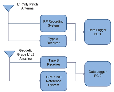
This data is a combination of field-data collections and a series of RF record playbacks. The field vehicle-mounted test setup included two GPS receivers, a GNSS L1 RF data recording device, and a high quality GPS/INS reference system (Figure 2). Type A receiver is a hi
gh-sensitivity enabled, automotive-grade GPS L1 receiver using a patch antenna, WAAS-capable although WAAS usage was disabled in the real-time data collection. Type B receiver is a high-quality L1/L2 receiver using a geodetic-grade antenna, used with WAAS enabled. The GPS/INS system was connected to the geodetic-grade antenna. The RF recording system was also connected to the automotive-grade GPS L1 antenna.
Figure 2. Vehicle test set-up.
The data was collected on a test route in Detroit, Michigan, that included durations of urban and deep urban canyon (40 miles per hour (mph) or less), freeway (55–70 mph), and suburban/local (30 mph) driving.
The RF data were subsequently replayed to GNSS receivers that were not a part of the field set-up. RF data was also replayed to receivers with forced sky-visibility obstructions and various WAAS settings. For limited sky-visibility tests, certain satellites were removed from each receiver’s view by receiver-specific configuration software. The satellite selection and restriction was done to mimic typical sky-view obstructions encountered in normal driving.
Type A receiver was chosen to illustrate the impact of visibility differences. A total of 13 satellites were visible in the entire data set (Figure 3). To create obstructed sky-view scenarios, two Type A receivers were configured to not use certain satellites in their position solutions. These configurations were:
Configuration 1 (C1): PRNs 7, 10, and 13 blocked
Configuration 2 (C2): PRNs 6, 16, 21, and 31 blocked
C1 mimics a vehicle/receiver with no visibility in the Northwestern part of the sky, whereas C2 mimics a receiver without visibility in the East/Northeastern part of the sky. Sky visibility restrictions do not vary with the heading changes of the vehicle. For example, for C1 receiver, Northwestern sky is always obstructed regardless of the vehicle orientation.
Figure 3. Sky view during the test.
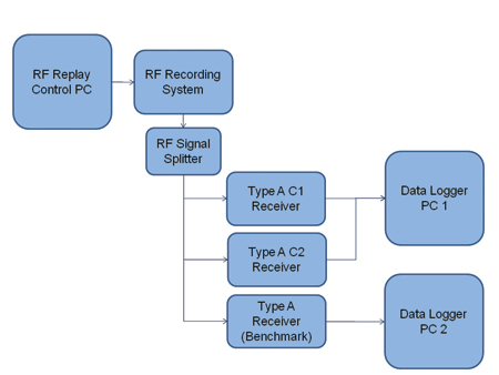
Figure 4 shows an example RF data replay setup. The record and replay system was controlled through a PC and the recorded data was also stored in the controller PC. The output RF signal was split into multiple outputs such that multiple receivers can be tested at the same time. For each replay of the RF data, a benchmark receiver was also used to verify that there is no run-to-run difference as a result of the RF replay.
Outputs from each GPS receiver from field and replay runs were logged to PCs using receiver specific binary formats. The recorded output from each receiver included its position, position error estimate, velocity, satellite-specific measurements and indicators such as pseudorange, carrier phase, and signals-to-noise ratio.
Figure 4. RF data replay set-up.
Data Processing and Analysis
The data was first decoded from the receiver-specific formats to a common format, then corrected for antenna offsets. To simplify the process, the reference system position solution was translated to the position of the test antenna using the known between-antenna distance and orientation of the vehicle as measured by the reference system. As a result, all the receivers and the reference system are reporting the location of the test antenna. Then, data fields such as position and velocity for each receiver were time-matched with the reference solutions, and the actual error was calculated.
For a limited dataset, additional measurement-level differential processing was done to show the difference between a DPOS and an RTK or a code-based differential relative position solution.
Figure 5 shows a plot of the 2D position error observed from each receiver during the test as a function of driving environment. Overall, Type B receiver shows better accuracy as expected from a dual frequency high quality receiver. However, it shows spikes of large error increases at times, mostly observed in the freeway scenario with large error excursions. With Type A receivers, relatively larger errors are observed with the limited-constellation receivers.
Figure 5. Position error (2D) of each receiver as a function of driving environment.
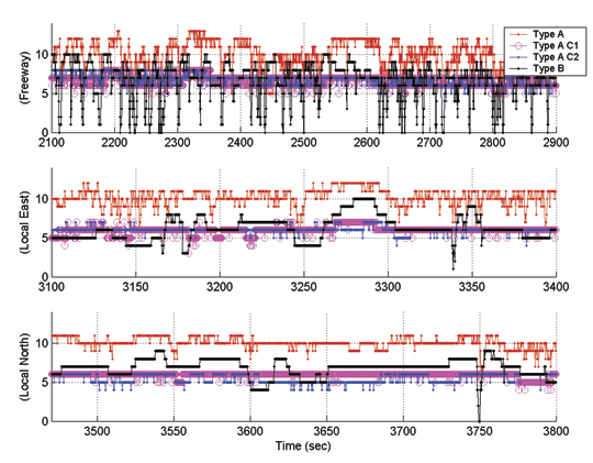
Figure 6 shows the number of satellites used by each receiver in the same environments as in Figure 5. Overall, Type A receiver tracks and uses on average 2–3 satellites more compared to the Type B receiver, likely due to its high-sensitivity capability. Type A C1 and C2 receivers also track and use 2–3 satellites fewer compared to the all-in-view Type A receiver.
Figure 6. GPS satellites used by receivers.
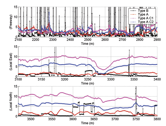
Freeway Data. The vehicle heading in this segment was predominantly north or northwest. The sky view can be considered a combination of urban and open sky conditions. As highlighted in Figure 6, all-in-view Type A receiver was able to use up to 11 GPS satellites with an average of around 9 satellites. Type A C1 and C2 receivers used, on average, about 3 satellites fewer than the all-in-view receiver. All three receivers show satellite count drops down to 4 at certain times in this segment.
The satellite count of the Type B receiver shows the limitations of not using the high-sensitive tracking capability. The satellite count shows frequent drops below 4 satellites and on occasion down to no satellites used.
Although the satellite count difference between all-in-view Type A and C1/C2 receivers was forced by means of receiver configuration, short-term sky visibility restrictions that resemble these conditions are in fact possible. Examples include a passenger car driving next to a semi truck or the side wall of the freeway in below-ground road sections.
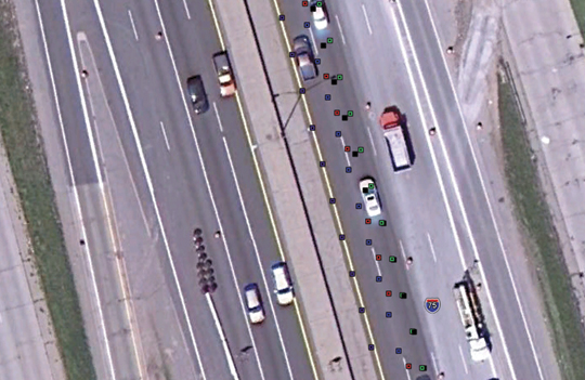
Figure 7 shows the position outputs of all four receivers on a satellite image of a short segment of the freeway. The true location (reference) is shown in green. Type A, Type B, Type A C1, and Type A C2 are shown in red, black, purple, and blue, respectively. These colors identify the four receiver types in all figures for the rest of this paper. While biases can be seen in the outputs of all four receivers with respect to the reference, the Type A C1 shows the largest offset with the magnitude of more than a lane width.
Figure 7. Freeway positioning accuracy.
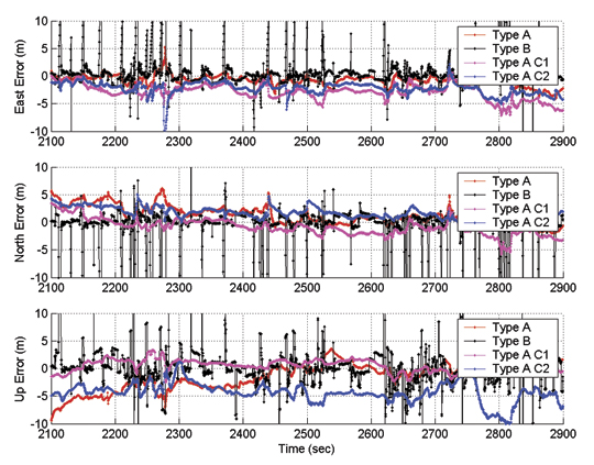
Figure 8 illustrates a time series of the positioning error components of all four receivers. It clearly shows error ramp-ups from the Type B receiver at frequent intervals. These coincide with the satellite count drops of Type B shown in Figure 6. No such error ramp-ups are observed for any of the Type A receivers, although relatively large biases of the order of few meters can be seen. As anticipated, larger errors are observed in the height direction.
Figure 8. Freeway positioning accuracy time series.
Local Road, Eastbound. This segment includes data gathered on an eastbound multi-lane local road with 40 mph posted speeds. As shown in Figure 6, a relatively larger number of satellites were continuously tracked in this segment as compared to the freeway. Therefore, this segment is considered to be an open-sky scenario with very limited number of obstructions. As shown in Figure 6, Type B receiver has used about 6 satellites on average, whereas the Type A has used around 3 more satellites most of the time. Type A C1 and C2 have also used around 3 satellites less compared to the all-in-view Type A receiver.
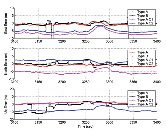
Figure 9 shows the vehicle position as reported by all three receivers and the reference system output for a short road segment in this drive. It clearly illustrates the lateral offsets of both C1 and C2 solutions. The C2 receiver (Blue) generated about a lane width offset towards north whereas the C1 receiver output is biased by around two lane widths to the south. Figure 10 presents a time series look of the positioning biases evident in Figure 9. It clearly shows large (more than 5 meter) biases in North and East position error components for C1 and C2 receivers.
Figure 9. Local (east) positioning accuracy.Figure 10. Local (east) positioning accuracy time series.
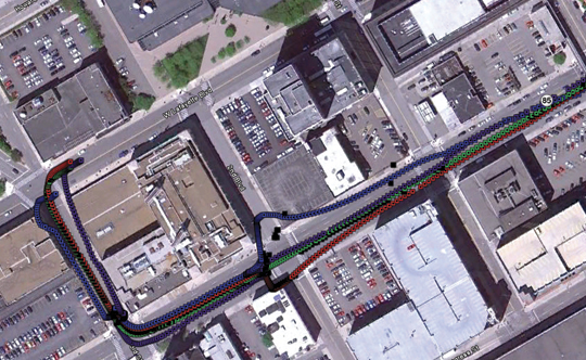
Local Road, Northbound. In roadway characteristics, this resembles Local Eastbound. Figure 6 shows the sky view remained almost unchanged for Type A receivers. For Type A C1, the count remained at 6 throughout. C1 and C2 receivers tracked 2–3 satellites fewer compared to all-in-view Type A. Interestingly, Type B experienced two dropouts of 4 or fewer satellites during the run. Figure 11 shows the position output of all receivers on a short road segment. As in the case of Local (East), significant biases can be readily observed in the output of C1 and C2.
Figure 11. Local (North) accuracy.
Figure 11. Local (North) accuracy.
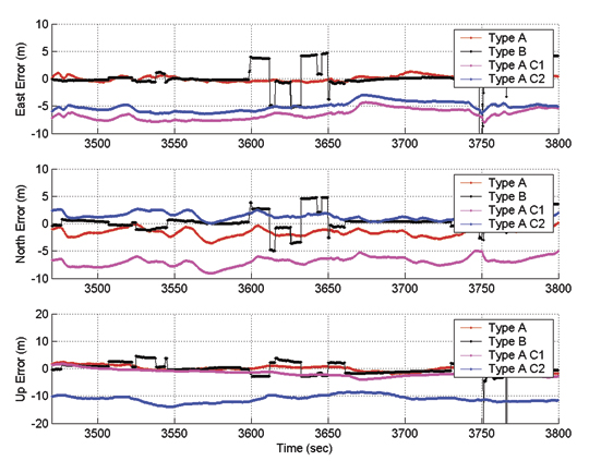
Figure 12 shows the time series view of the positioning error in this segment, confirming that the biases observed in Figure 11 are not short-term biases, but are in fact vehicle heading-dependent biases. The short-term biases seen in the Type B receiver output coincide with the change in the number of satellites used (shown in Figure 6). This illustrates the implications of different estimation methods used in the two receiver types. For instance, Type B receiver allows stepwise changes in its position estimate whereas Type A output tends to gradually converge to different states.
Figure 12. Local (North) positioning accuracy time series.
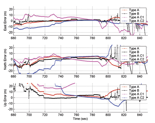
Urban Canyon. Results of the urban canyon segment of the drive are shown in Figures 13 and 14. A statistical analysis is not presented for this segment, as receiver type and configuration dependent biases and errors are difficult to isolate from the errors that are the result of multipath and measurement noise. In Figure 14, much larger biases in the order of 10 meters or more can be seen for all three Type A receivers. In comparison, Type B receiver tends to output a relatively accurate position solution whenever it has sufficient satellites visible. In the case of less than optimal satellites availability, Type B receivers tend to show rapidly degrading positioning accuracy, which may be reliably detected using its quality indicators.
Figure 13. Urban canyon accuracy.
Figure 14. Urban canyon positioning accuracy time series.
Position Error Distributions
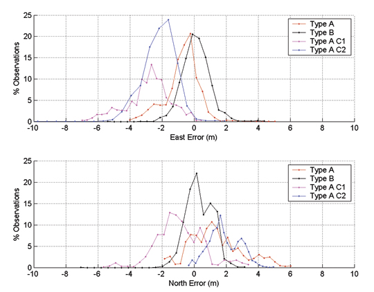
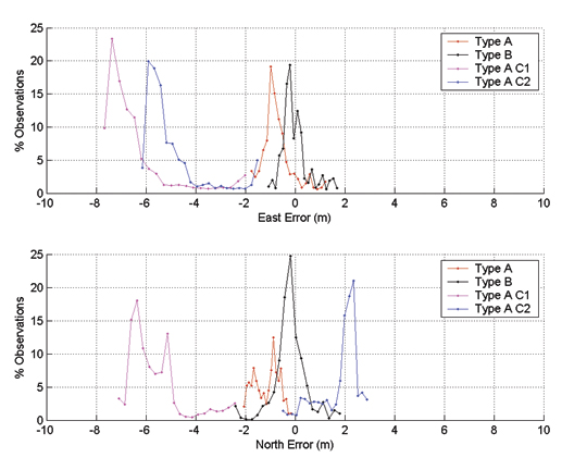
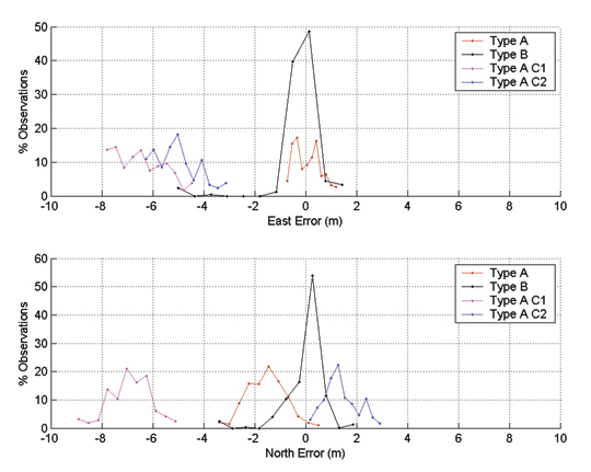
Position error probability distribution functions were generated for the first three road segments using the time series data above. Figures 15-17 show these functions for Freeway, Local (East), and Local (North) segments, respectively. They lead to these general conclusions:
Based on the mean and the spread of the distributions, Type B receiver has consistently provided the most unbiased and accurate positioning performance out of all the receivers considered. Overall, the output appears to be unbiased, as should be the case for a high quality dual frequency receiver with WAAS capability.
Type A all-in-view receiver shows the next best overall accuracy statistics with some biases in certain cases. These biases can be time-of-day-dependent and may differ for different times of the day or if observed over a longer time.
Type A C1 and C2 receivers show very significant vehicle-heading-dependent biases/errors. This is with very limited sky view obstructions (that is, C1 only restricts less than 1/8 of the entire sky view whereas C2 covers around 1/4) and with the same type of the receiver.
Although enabling WAAS should theoretically help minimize the biases observed in these tests, the availability (open line-of-sight) of WAAS satellites for automotive applications in these environments must be taken into consideration for WAAS accuracy benefits to be applicable. For these datasets, WAAS signals availabilities for a Type B receiver were 58 percent of total driving time in urban canyon, 60 percent in the freeway scenario, 95 percent and 99 percent in the local road scenarios.
Figure 15. Freeway position error distribution.Figure 16. Local road (east) position error distribution.Figure 17. Local road (north) position error distribution.
Velocity Domain Performance. For each test segment, velocity estimates from each receiver were logged at the default data rate of 4 Hz. For analysis purposes, North and East velocity readings from each receiver were converted to 2D speed estimates. These were used with reference system speed estimates to generate 2D speed error statistics (Table 1).
Based on Table 1, no significant biases or errors were observed from any particular receiver or configuration. The only exception was the increased errors in the Urban Canyon segment, particular for C1 and C2. This is expected .to be a result of limited satellite availability in a challenging environment with additional forced satellite eliminations.
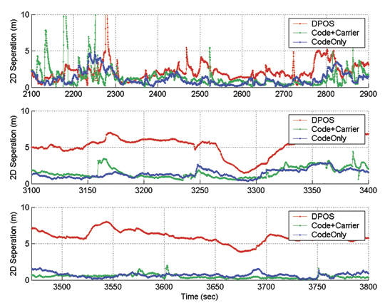
Virtual Two-Vehicle Analysis. Assume that Type A and Type A C1 receivers were located in two vehicles. Ideally, both receivers should report the same location, as they were both connected to the same antenna on a single vehicle, creating a zero-baseline scenario. However, as shown in the previous section, a meter-level separation was observed between the two solutions.
In this virtual two-vehicle scenario, relative position of one receiver (Type A) with respect to the other (Type A C2) was estimated by three methods, using GNSS data processing software in post-mission. The methods were:
Differenced Positions (DPOS). Latitude and longitude reported by each vehicle were time-matched; distance between the two points was calculated.
Code and Carrier. Single frequency (L1) GPS RTK positioning with float ambiguity estimation.
Code Only. GPS code measurements generated a relative position solution.
The 2D receiver separation results of this processing are shown in Figure 19 as three subplots for freeway (top), local/east (middle), and local/north (bottom) scenarios. The 2D separation results for local scenarios show clear performance benefits for the GNSS measurements-based methods. In both east and north local scenarios, around a 5-meter bias is observed in the DPOS solution whereas this is reduced to around a meter in both code-only and code and carrier methods. The freeway scenario shows relatively smaller difference potentially due to measurement noise, multipath, and frequent interruption of sky view. Table 2 shows mean values of these results.
Figure 18. Position separation for processing methods.Table 2. Mean Accuracy (meters) using processing methods.
Discussion
OTA transfer of certain GNSS measurement data elements appears to be a critical requirement for reliable lane-level positioning capability. However, the method must be capable of supporting a certain level of performance even in challenging environments for GNSS. The solution for such challenging environments is likely to be GNSS integration methods with vehicle-based sensors (that is, GNSS/INS) for the foreseeable future.
Given these facts, a reliable and accurate V2X relative position method will require the OTA transfer of a combination of critical vehicle states which include the vehicle location, a confidence measure, and certain GNSS measurement data elements. With its ability to support all of these needs, the SAE J2735 provides a basic framework for further refinement of relative positioning technologies for automotive applications.
A reliable position confidence measure broadcast over-the-air is also a critical need, particularly if GNSS measurement data is not broadcasted on a regular basis. This also holds true for conditions under which a vehicle may be operating in a GNSS and vehicle sensor integrated mode or with less than optimal number of satellites in view. However, estimating such a parameter that can be trusted with high degree of confidence can be challenging given the presence of various biases that can depend on the environment, vehicle, GNSS receiver, and sensors and methods used. Potential examples are time-of-day, vehicle heading, vehicle speed, GNSS receiver/sensor type, model, and configuration. However, developing a parameter similar to the RTCA Horizontal Uncertainty Level (HUL) for automotive applications is an important consideration.
While there are many other candidate receivers to be considered for a study of this nature, only two receiver types were used in this analysis. Analysis of more receiver types can be beneficial to identify the desired characteristics for a certain applications. A consideration could be achieving a desirable balance between accuracy and the sensitivity of the GNSS receivers, as increased sensitivity often produces higher solution availability at the cost of degrading accuracy.
Another area to investigate in related work is the benefits of using WAAS under the test conditions given in this paper. The general expectation is to see less bias in the position solution with WAAS as the ranging errors are likely to be smaller as a result of WAAS corrections. However, for automotive applications in particular, availability of WAAS signals to land vehicles need to be investigated.
CHAMINDA BASNYAKE is a senior research engineer at General Motors Global Research and Development and GNSS technology expert for GM OnStar. He leads GNSS-based vehicle navigation technology R&D efforts at GM and holds a Ph.D. in geomatics engineering from the University of Calgary.