TeleCommunication Systems (TCS), a provider of mobile communication technology, announced that its TCS VoLTE9-1-1 service is first into production with Tier-1 wireless carriers, including two of the largest North American operators. The fully customizable solution enables 4G/LTE carriers to provide both 911 call routing and originating coarse/precise location information, including the 10-digit callback number, to public safety access points (PSAPs).
Initially, wireless carriers deployed 4G/LTE solely for data use. Without VoLTE9-1-1 capabilities, carriers must process emergency calls over 3G networks (circuit-switched fallback), even in areas where LTE is deployed. However, with TCS’ VoLTE9-1-1 service, they can now process 911 calls in an all-LTE environment, enabling them to reclaim or reuse 3G spectrum.
“As carriers increasingly move toward LTE networks, the ability to handle 911 emergency communications is critical,” said Thomas Ginter of TCS. “By leveraging VoLTE9-1-1, network operators are helping to ensure subscribers receive the responsiveness they need in an emergency situation, while expanding coverage to areas where 3G coverage is lacking.”
TCS VoLTE9-1-1 features:
Call routing to the PSAP: The TCS VoLTE9-1-1 service routes a 4G/LTE-originated 911 call using coarse location via the route determination function component.
PSAP telecommunicators can call back if disconnected: The TCS VoLTE9-1-1 service remains fully backwards compatible, supporting necessary functions such as providing PSAPs with full 10-digit subscriber callback numbers.
Re-bid by a PSAP for precise location after call routing: The location retrieval function allows a wireless carrier complete flexibility in choosing its underlying high-accuracy location technology and supports updated/precise position requests.
Emergency voice call continuity for location service: Location continuity and location delivery to the PSAPs are supported in usage scenarios where the 911 call switches from 4G/LTE to 3G/2G networks.
Expansion beyond voice: As wireless networks advance, multimedia objects such as text, audio and video can be transferred to a compatible termination point with LTE IP networks, for example, an NG ESINet and i3 PSAP. Leveraging an all-IP network makes it easier and more cost effective to interconnect services.
Small cell support: The TCS VoLTE9-1-1 solution supports small cells, including femtocells, microcells, and picocells, which are now commonly used in dense urban, indoor areas and enterprise networks.
TCS supports half of all U.S. wireless E911 calls, serving more than 140 million wireless and IP-enabled devices. The company holds more than 280 patents, 43 of which relate to public safety, and more than 360 pending worldwide.
Indoor location research and fielded developments currently focus on consumer-level applications, mostly using mobile phone handsets, but this work will hopefully also benefit professional and high-precision uses of GNSS. Indoor location technologies could be of particular interest in machine control for warehousing, industrial assembly, indoor and even underground mapping, underground mining, in forestry where dense canopy virtually cuts out GNSS, construction, and other areas where sky-view is limited or negligible.
Tune in to Indoor Nav Webinar Thursday
Tune in to GPS World’s webinar, “Indoor Positioning and Navigation: Results of the FCC’s CSRIC Bay Area Trials,” on Thursday, April 18. Speakers include Khaled Dessouky (Technocom); Ganesh Pattabiraman (NextNav); Norm Shaw (Polaris Wireless); and Greg Turetzky (CSR). Registration is free.
Professional users will want to keep abreast of developments in the E-911 area, and be aware as achievable accuracies begin to approach what could be possible for precision applications. Right now, that’s maybe a pretty big stretch, but taking a look periodically is a good idea. A recent round of landmark tests by the Federal Communications Commission (FCC) provides just such an occasion for a look-in.
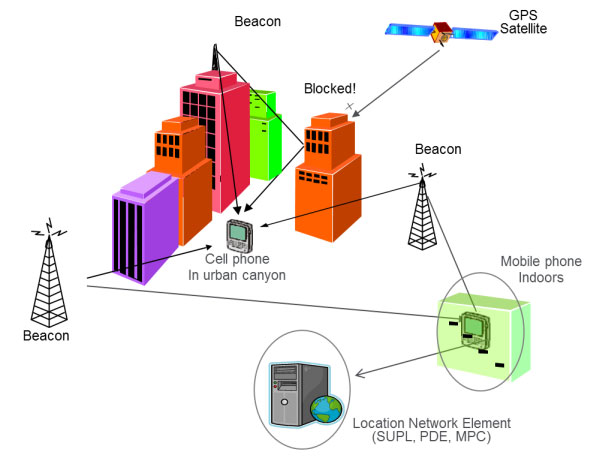
The U.S., E-911 legislation put in place back in 2001 required that both landlines and cellphones should provide the location of callers to within specific accuracy levels. Location information was to be sent transparently to Public Safety Answering Points (PSAPs) which would allow fire/rescue/police personnel to be dispatched to the location of the 911 call. For mobile phones, cellphone manufacturers and network providers forged ahead and implemented a number of location strategies using differing technologies — all require being outdoors where a clear sky-view is available.
GPS and augmented GPS technologies were only part of the cellphone solution. Other implementations included use of the cell-signal itself, along with an extensive database that can contain, amongst other things, signal attributes and network asset locations. Turns out that, today, around 60 percent of mobile phone calls are made within buildings, so the FCC started to investigate how to bring E-911 capability to indoor calls.
In 2011, the FCC commissioned a group called the Communications Security, Reliability and Interoperability Council (CSRIC), and Working Group 3 (WG-3) is the one currently investigating what can be done for indoor E-911 location. Drawn from interested industry participants, the WG-3 Location-Based Services (LBS) sub-group set about finding what technologies exist, how well they work, and how they could be applied to E-911. Now, there are a lot of people trying to crack this problem and many, many ways that it’s been tackled — all of which are at different stages of development and with differing levels of capability. In order to make definitive progress, WG-3 LBS decided that a test-bed was the best way to evaluate and compare what’s currently available.
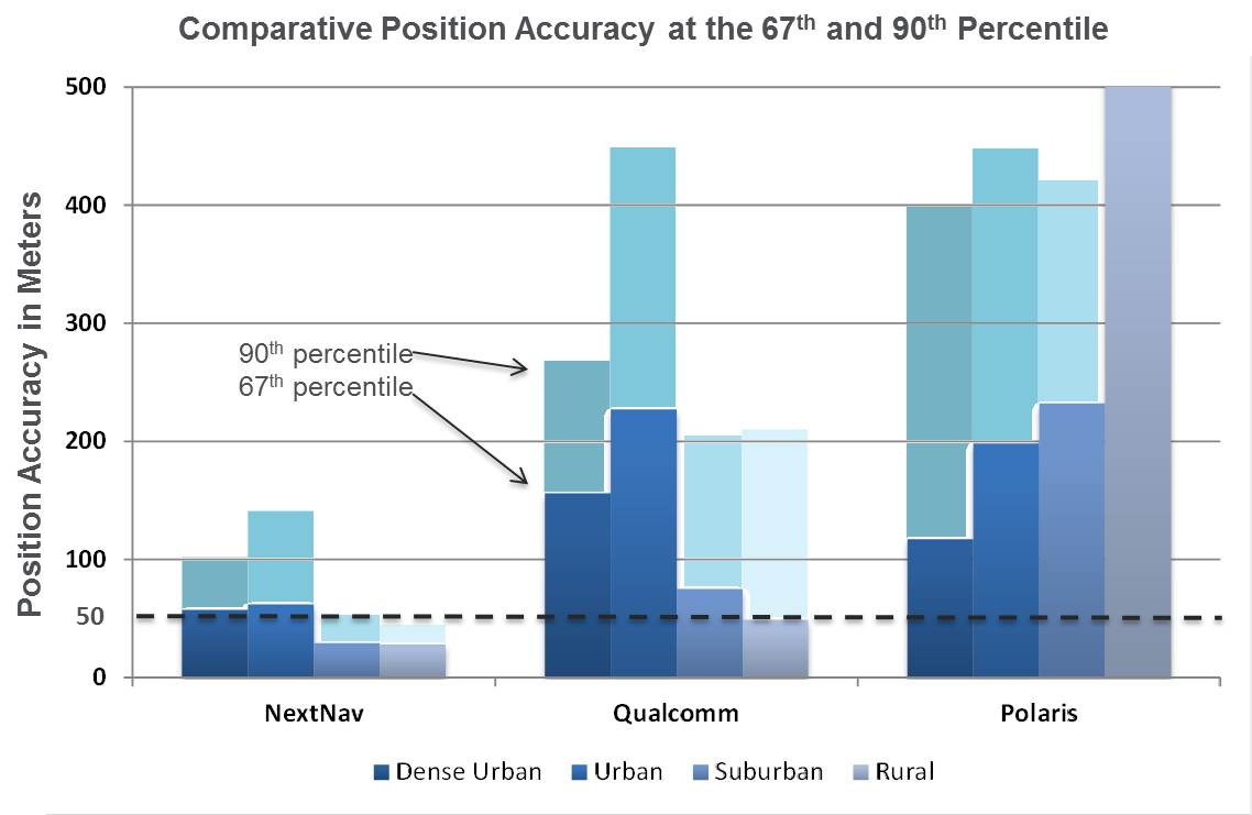
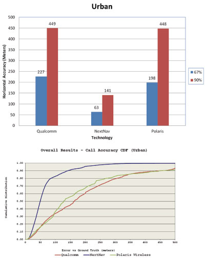
Seven vendors signed up initially, but only three — NextNav, Polaris Wireless, and Qualcomm — completed the rigorous testing, which set out to basically establish horizontal and vertical accuracy, speed of location, and reliability and consistency of results for each system. The trial tested the performance of location systems across urban, suburban and rural areas in the San Francisco Bay Area. More than 13,000 test calls were placed from various tested technologies in 75 different indoor locations selected by participating public safety organizations from around the U.S. Click here for the full report.
In the tests, Polaris Wireless used an RF pattern matching/fingerprinting technique, Qualcomm used a hybrid Assisted-GPS (A-GPS)/Advanced Forward Link Trilateration (AFLT) system, and NextNav used wireless beacon technology. NextNav came out on top, and largely within the magical 50-meter “search ring” requirement, and was the only vendor to provide vertical location capability.
NextNav uses pressure transducers in its beacons and in the handheld units to accurately measure calibrated altitude — within about 2 meters — so it can actually report the floor where the handheld is located; it’s the only system tested that was able to do so. Apparently the use of MEMS pressure sensors in cellphones is forecast to increase to 681 million units in 2016, so this could be the right approach.
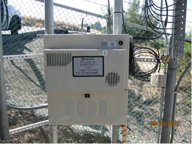
NextNav is focusing on the San Francisco market, where the company has fielded a significant number of beacons, but it has also placed beacons in another 40 metropolitan locations across the U.S. NextNav has acquired appropriate spectrum rights to transmit a 900-MHz “GPS-like” signal that’s synchronized to GPS. This enables good penetration into most urban buildings — both high-rise and those with fewer floors.
To support adoption of its solution, NextNav is working with a chipset manufacturer to incorporate processing of its location signal within an upcoming spin of an embedded cellphone chipset. While other solutions have adopted Wi-Fi and cell-signal solutions, NextNav contends that its approach is the most cost effective, as beacon deployment is geographically less dense and can be amortized over so many users.
NextNav Beacon.
Other solutions also apparently rely on the use of databases that store signal characteristics and a number of other parameters – the CSRIC report highlights the complexity this brings to database management and maintenance. NextNav also has a database, but this is basically to store records of location, cable configurations and calibration data. This is only used to ensure consistent performance of their system; it’s not required for network operation or location.
Higher precision applications would also benefit from this type of augmentation in the same way that WAAS users achieve higher accuracies, except this system uses local beacons, and there could be the potential for even higher precision with known fixed beacon locations within urban environments. As commercial UAV applications grow, it’s not impossible that there will be higher precision flight applications within cities, for geo-location surveying, building and outside appliance inspections, signal mapping, traffic mapping, road-work repair monitoring — in fact, many of the monitoring activities we see daily in towns and cities where a view of the sky can be particularly restricted.
The CSRIC participants are not the only ones pursuing the holy grail of indoor location. As mentioned, seven different location vendors/technologies began the process to demonstrate their performance indoors through the common test bed, but only three completed the process. The others remain highly motivated and involved, however, and at work tuning their varied solutions. The WG3 report states, “The following location vendors showed initial interest in having their technologies tested and highlighted through the test bed process, but ended up not participating in the Stage 1 test bed, for a variety of reasons.
LEO Iridium Satellite-based Positioning (BoeingBTL).”
Meanwhile, promising indoor location research goes on at a number of commercial and academic institutions, such as the University of Calgary PLAN group, which has focused on integration of Wi-Fi and GPS. An upcoming paper reports that Wi-Fi, using the 802.11 standards, can be employed in several different ways as a complementary positioning technology for GPS/GNSS navigation, and the two can be used in an integrated framework to provide a continuous and robust positioning service.
Another promising component for indoor location could be the recent release of a software application by Baseband Technologies, which can provide rapid ephemeris for up to 28 days, between ephemeris downloads from GPS directly or over cellphones from the Internet. But indoor location warrants much more extensive treatment than these few random comments — what’s summarized here are only some recent developments in E-911.
There will likely be another round of E-911 test-bed activities if funding and management issues are resolved. See CSRIC WG-3 LBS Subgroup member Greg Turetzky’s “Expert Advice” column from GPS World for perspective and a forward look. We can anticipate even wider participation by differing technologies and even greater levels of performance in future. Longer term progression towards higher precision professional applications seems to be inevitable.
Communications Security, Reliability, and Interoperability Council (CSRIC) Update
By Greg Turetsky
Many of us remember way back in 2001 when the FCC first announced E911 position reporting requirements for cell phones. That was a long time ago in many significant ways. Everyone had 2G phones and anxiously anticipated the arrival of 3G, and with it, data. Most people still had a landline at home, and used their mobile sparingly lest they overrun their monthly minutes. Roaming was very expensive and nearly impossible overseas. Very few phones had GPS, and people only turned it on when needed, as it significantly reduced battery life.
Now, in 2013, all of the technology has changed, but — not unexpectedly — the regulations have not. This is one of the reasons the U.S. Federal Communications Commission (FCC) created CSRIC.
The Communications Security, Reliability, and Interoperability Council’s mission is to provide recommendations to the FCC to ensure, among other things, optimal security and reliability of communications systems, including telecommunications, media, and public safety. The current council, CSRIC III, was born on March 19, 2011, and ended on March 18, 2013. Working Group 3 (WG-3), the E911 Location Accuracy group, has looked into both outdoor and indoor location accuracy issues to help the FCC shape new guidelines. I don’t think any of us would argue that given the current patterns of cell phone usage, the ability to provide a location indoors to a public safety answering point (PSAP) is something that is now needed, has significant value to the public, and would seem to lie within our grasp technically.
Working Group 3 is a fairly large group of experts from a wide variety of backgrounds. The actual list of participants is publicly available; what’s more interesting is the groups that they represent. Three main constituencies constitute the Working Group: the public safety community, the wireless operators, and the technology vendors. Each group has a slightly different goal, but they all worked well together to produce clear, unbiased reports that represent all the different members’ views in a way that lends more credibility to the overall report.
On March 14, the FCC released two reports created by WG-3: the “Indoor Location Test Bed Report,” and “Leveraging LBS and Emerging Location Technologies for Indoor Wireless E911 Report.” I will not review either document here as they are available publicly, but I will summarize the highlights of the reports from my perspective as a member of the location community and a concerned citizen, and attempt to predict where the process might lead next.
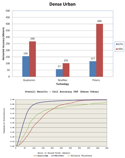
Figure 1. Indoor accuracy in the dense urban environment.
Test Bed Report. In my mind, two key results emerged from the Test Bed Report. The first was very positive: the test bed showed that there are technologies capable of yielding positions indoors, and their performance can be compared analytically. This may seem like a bland statement, but it carries a significant amount of weight with both the public safety community and the FCC. It acknowledges that the technology has evolved sufficiently such that in a test bed setting, we can gather and compare, in an apples-to-apples way, the performance of diverse technologies in terms of yield and accuracy. Similar to the LightSquared reports, this report focuses on ensuring that the data itself is valid. The interpretation of the data is far too politically and economically charged to be agreed on by all parties involved. It is a great accomplishment to concur on a methodology by which testing should be done, and to produce a set of results that can be given to the FCC with the entire council’s approval.
The second highlight from my perspective was less positive. The test bed originally had seven participants, but in the end only three completed the process. This indicates that there are even more candidate technologies for solving the indoor E911 problem — but for a variety of reasons, they were not ready for CSRIC testing at this juncture. Although having three choices is good, seven (or even more) would be better for the FCC to feel confident in its ability to create a new mandate with sufficient flexibility on implementation. There are clearly many ways to skin this cat technically, but we have to ensure that the test bed methodology allows as many as possible viable alternatives to be compared. There is clearly a gap between those technologies that are commercially available and those that can be used for E911.
Leveraging LBS. The Leveraging LBS Technology report also reached some interesting conclusions. The concept of leveraging LBS was actually how I became involved in the CSRIC. The underlying question that the FCC asked me to explore was “Why can a smartphone user can get a dot on a map indoors (usually with an uncertainty circle, no less), but no location information shows up on the PSAP screen if he makes an E911 call?”
As we dug into this problem, it became clear that this was less of a technology problem and more of a business/policy one. Quite a few large companies make money by providing that indoor location for various applications, but there isn’t any real money in E911 — although there are lots of liabilities. Also, many of these solutions are proprietary either to the phone, the operating system, or the application, while an E911 solution would need to be standardized across all of those as well as different carriers.
Figure 2. Indoor accuracy in the urban environment.
Conclusion. The FCC has received two reports with similar conclusions: We have come a long way since 2001, but we might not be there — the indoor E911 promised land —just yet.
There is still more to come, however. Therefore, many participants and observers hope the work of the current CSRIC will lay the foundation for a rational conversation about indoor E911 right now, and still be around to allow for future improvements. We have recommended that the test bed be maintained so future results can be compared with current ones. At issue is the funding source for the test bed. The FCC has announced the coming of a CSRIC IV, but has not released any further details. It is certainly the hope of WG-3 that the work performed to date to establish and validate the test bed will be available for use by future technologies as they mature.
Locating emergency callers indoors is a critical capability that we as society must address — not for the callers’ convenience, but for their safety and or public safety generally. The problem has technical, commercial, regulatory, financial, legal, and public safety facets to it, making it a very complex issue.
I should also note, that although E911 is a U.S. regulation, the problem of indoor location is under scrutiny in nations all over the world. I earnestly hope that all sides can continue working together to find a solution that can be implemented for the benefit of everyone.
Greg Turetzky is senior director, CTO Office, for CSR. He served on the CSRIC Working Group 3 LBS Subgroup. He will participate in a April 16 GPS World Webinar on this topic. Registration is free.
Noting that the arena in which cellular emergency calling (E911) and location-based services (LBS) must be delivered has grown significantly more complex, Spirent Communications has expanded its LBS LTE test solution to support long-term evolution (LTE) positioning protocol (LPP) and observed time difference of arrival (OTDOA). The deployment of wireless LTE networks enables the introduction of new positioning technologies and protocols for communicating location information between the main network with exciting consequences for the mobile device entities, and new services they can enable.
“In 2911, we launched the secure user plane location (SUPL) 2.0 test capabilities on our LTE test solution for successful deployments of LTE SUPL positioning.” said Robb Van Brunt, vice president oaf Spirent’s Wireless business. “Our latest enhancements include extensive test coverage for SUPL 2.0/LPP and a fully automated system for testing user equipment performance for LPP and OTDOA. With our unique e understanding of the importance and complexity of these technologies, Spirent can assist customers in expediting the delivery of new location-based devices for the growing number of LTE networks.”
OTDOA is an LTE positioning technology that allows for an enhanced user experience of LBS indoors or in other areas where GNSS do not work well, and in doing so also serves assa key component for supporting E911. Based on timing measurements from multiple base stations signals, OTDOA can also be combined with GNSS measurements, creating a hybrid approach to deliver an even more significant LBS performance improvement.
LPP is the positioning protocol that enables OTDOA along with numerous other positioning technologies on the LTE network. LPP is a control plane protocol that can also be used for user plane positioning, in conjunction with SUPL 2.0.
Spirent’s expansion to its LTE LBS Test Solution supports LPP minimum performance testing, as well as a completely automated system for testing UE positioning performance, including OTDOA accuracy measurement analysis.
In the next two to four years, mobile device location platforms will be able to provide positioning performance that enables emergency call (E911) and location-based services (LBS) with excellent accuracy (5–10 meters) in all locations. We call this accurate everywhere location, and it will be a significant enabler of indoor navigation applications and for even wider adoption of consumer LBS.
In fact, we may eventually forget how we ever lived without it. This technology can enhance our lives by enabling our mobile devices to know precisely where we are at all times. Armed with this information, our devices can behave in a way that suits our specific situation, and they can do this without us having to do anything other than keep the phone with us.
Text and images will get significantly bigger while driving or walking. Facebook notifications can be automatically disabled while at work. Shopping lists can be automatically displayed when approaching a store that has an item on the list. The potential benefits are endless — provided that the privacy issues associated with location are handled appropriately.
GNSS is the superior technology when a mostly unobstructed sky is available, but it can’t deliver accurate position fixes in all environments — at least not at a cost and in a form factor that works for consumer mobile devices. Accurate everywhere location requires some form of advanced hybrid location technology. Because its definition is constantly evolving, the term hybrid can mean different things to different people. This article aims to clear that up.
Here is an overview of the hybrid positioning technology currently used in mobile devices, as well as what is coming in the next two to four years that will enable accurate everywhere location:
GPS + GLONASS. Multiple GNSS technologies are starting to be more common in new chipsets aimed at mobile devices, and assisted-GPS (A-GPS) + A-GLONASS is right around the corner. The benefit from this hybrid GNSS approach is that with more satellites in the sky, devices are likely to receive more line-of-sight signals in challenging environments where a significant portion of the sky is obstructed (like urban canyons). While this might improve performance on a street in downtown Manhattan, it does not help when you are in the middle of a building or in the subway.
Cellular Multilateration + A-GNSS. Mobile devices with CDMA cellular radios have supported hybrid A-GPS + advanced forward-link trilateration (AFLT) for more than a decade. This concept is now being applied to long-term evolution (LTE) devices, with support for A-GNSS + observed time difference of arrival (OTDOA) being written into the 3GPP standards. Both AFLT and OTDOA are forms of cellular multilateration, which means that devices can make measurements of relative timing offsets between multiple downlink cellular signals, and those measurements can be used in a hyperbolic multilateration formula to compute a position (one signal acts as reference and hyperbolic intersection of 2+ signals are used for position).
Does this sound familiar? It happens to be very similar to GNSS location computation, so it is possible to combine measurements from cellular signals and measurements from GNSS satellites to compute a hybrid position. For example, 2 satellites + 2 cellular measurements can be combined to compute a position, which makes this technique very attractive. Although it is used for both E911 positioning in North America and LBS worldwide, this technology will become even more widespread as LTE adoption increases.
A-GNSS + Wi-Fi Positioning + eCID. Many popular smartphones today support Wi-Fi positioning and enhanced cell ID (eCID) in addition to A-GNSS. This hybrid solution allows coarse positioning in indoor environments where A-GNSS does not work. Solutions for Wi-Fi and eCID positioning are currently very fragmented and proprietary. However, this is the reason you are able to get a semi-accurate position fix on your Android or iOS mobile device when GNSS satellites are impossible to measure (many other devices support this as well). These technologies are going to provide more accurate information as time goes on, but we don’t believe they will achieve accurate everywhere location on their own.
A-GNSS + Wi-Fi Positioning + Cellular Positioning + Sensors. You might have guessed it, but we think accurate everywhere location will be enabled by a combination of all the above hybrid techniques plus one more important technology: sensors. Integrated sensors like accelerometers, magnetometers, and barometers enable devices to sense changes in direction, orientation, and elevation. Given an accurate starting location (for example, GNSS position fix), sensors can track location accurately for several minutes (and this will continue to get better). Location error will accumulate over time, but this can be minimized when Wi-Fi, cellular, and GNSS positioning are used in conjunction to constrain the error. Furthermore, barometers can be used to track elevation changes, thereby allowing devices to know exactly what floor of a building a user is on. Other technologies, or signals of opportunity, may be used in the future to further improve performance, but we think this mix of A-GNSS, Wi-Fi, cellular, and sensor positioning is the key to accurate everywhere location in mobile devices.
With substantial R&D dollars being spent now, and standardized testing for hybrid positioning emerging this year, our best estimate is that the accurate everywhere technology will become commercially widespread by 2015.
Brock Butler is director of Spirent’s Wireless Location Technologies, part of a team that has made major contributions to development of the LBS standards in the 3GPP: Spirent filled the editor and rapporteur roles for the TS 51.010 and TS 34.171 A-GPS Terminal Conformance Specifications, as well as the editor role for the Enabler Test Specification for SUPL in the OMA. Butler holds a BSc in electrical engineering from Villanova University.
By Dinesh Manandhar and Hideyuki Torimoto, GNSS Technologies, Inc. Japan
An indoor messaging system (IMES) has been developed to meet the challenges of indoor and deep indoor positioning, as a system that can be implemented in any device that has a GPS/GNSS receiver without hardware modification. IMES can provide reliable 3D position data with a single transmitter device without performing range calculation.
The cost of embedding location data in portable electronic devices is so low that universal penetration can be foreseen in the next five years. Roughly 70 percent of the world’s population now uses approximately five billion cell phones. This number has doubled in the last four years. Future growth is expected at the same or even a higher growth rate.
Due to the emergence of smart phones and location-based services (LBS), mobile phones are used not only for communications but also for many applications related to LBS, entertainment, and games. GPS/GNSS devices are included in mobile phones due to compulsory requirement of E911 and safety-and-rescue services by law in many countries for security and safety.
Access to map data and value-added services using these map data is getting cheaper and eventually will be freely available. Major service providers like Google, Nokia, and Apple already provide access free of cost, and they increasingly focus on location as a core business construct.
GPS/GNSS devices were designed to work outdoors, and most GNSS applications are limited to outdoor environments. However, GNSS reliability, availability, and accuracy have led to development of many new and innovative applications that are designed for use in both outdoors and indoors in a seamless fashion. Today, GNSS receivers are integrated in many other devices like mobile phones, navigation systems, personal navigation devices, game devices, security devices, and many LBS-related devices. These devices are increasingly used in indoor environments. Indeed, people generally spend much more time indoors than outdoors. Hence, it is extremely important to have a reliable system that can provide fairly accurate position data even in indoor and deep indoor locations.
Current GNSS systems do not provide solutions for indoor and deep indoor environment with reliable accuracy of 10–20 meters. New modernized signals such as L5 do provide better position accuracy and better signal reception in indoor areas, but achievable positioning will still vary, and will continue to require more than four visible satellites with some assist data — and still be limited to soft indoors environments such as rooms with glass windows or walls. Limitations remain for hard and deep indoor environments.
To surmount these obstacles and provide indoor navigation, various technologies such as pseudolites, assisted GPS, wireless networks (Wi-Fi), Bluetooth, RF tagging, and so on have been developed. However, these technologies have their own limitations and are not the most suitable tools for seamless positioning and navigation. Except for pseudolite and A-GPS, they are designed for communication, not for positioning or navigation purposes, but are used for navigation purposes since no other suitable technology exist.
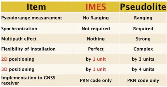
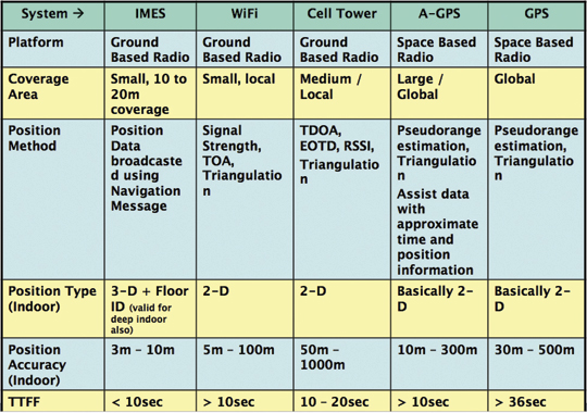
Pseudolite systems are currently in use for indoor positioning. While technically sound, a system needs at least four signal transmitting units. To cover a large area, it needs many transmitters suitably located and time-synchronized to one other, or their clock errors must be known. Pseudolite systems provide position data based on range calculation from the receiver to a number of transmitters, and this calculation is heavily affected by signal multipath. Table 1 compares IMES and pseudolites.
Table 1. Comparison between IMES and pseudolite.
A-GPS is widely used in mobile phones to compute position data. A-GPS technology includes high-sensitivity signal processing to acquire weak signals and external assistance of data like time, approximate position, and satellite-orbit related parameters. Provision of assistance data requires a communication link between the receiver and the data source, for example, the mobile phone network itself. Thus, A-GPS will not be possible if there is no communication link.
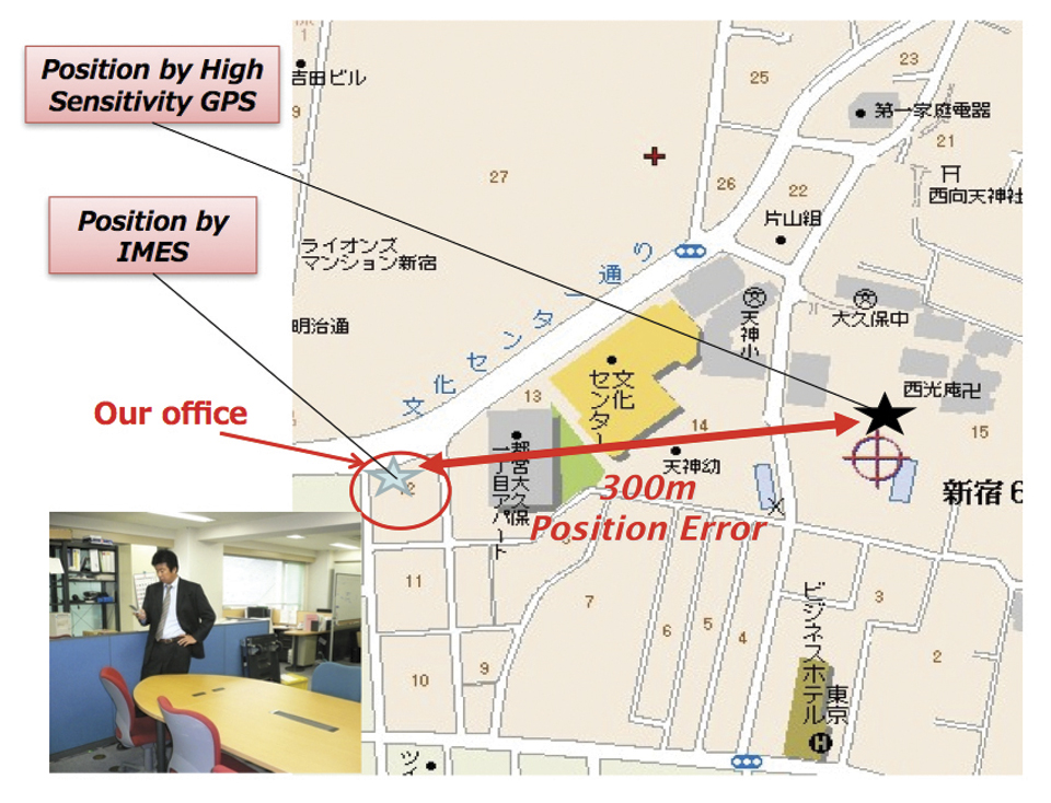
Normally, A-GPS provides 2D position data. The height data (if 3D output is available) will be highly erroneous. The accuracy of such position data varies from few tens of meters to few hundreds of meters. Also, the position data is heavily affected by signal multipath. Figure 2 compares IMES position and mobile phone position inside an office building. The A-GPS position error is about 300 meters in this case.
FIGURE 2. Indoor position from high-sensitivity GPS and IMES.
Wi-Fi is used for indoor positioning in many mobile phone devices. The phone provides position data from a built-in GPS receiver, a Wi-Fi device, cell ID, or a combination of any of these. Recently, position data from Wi-Fi has become popular for indoor as well as outdoor position, since Wi-Fi signals are so freely available. However, using these Wi-Fi signals requires registering the signal power and availability at reference locations. To do this, a huge number of Wi-Fi devices are registered driving around the city. Since these devices are basically installed for communication purposes, they can be relocated, removed, or new devices may be installed without any information to the users or service providers. Thus, continuous maintenance and updating of all these devices are necessary at certain time intervals. The coverage of Wi-Fi devices is not uniform and may vary widely from area to area, affecting position accuracy.
Telecom service providers are considering the possibilities of seamless positioning technologies. They would like to have one single device that can provide 3D position data both indoors and outdoors, without additional power or cost, and with satisfactory 3D position information. If such a seamless positioning technology is available, it will undoubtedly generate a huge global commercial market. The availability of such technology will also aid development of new applications in location-based services, advertising, marketing, entertainment, and gaming.
We have conducted research in indoor positioning for the past few years, beginning with pseudolite systems. We have developed IMES to meet the shortcomings of the technologies described earlier for indoor and deep indoor positioning. IMES for a seamless positioning environment can be implemented in any device that has a GPS/GNSS receiver, without hardware modification. IMES can provide satisfactory and reliable 3D position data with a single transmitter device without performing range calculation.
Table 2 compares IMES with other indoor-position capable devices. IMES can provide the same accuracy even in deep indoor locations, whereas cell tower, A-GPS, and GPS cannot work in such areas. All other systems except IMES provide only 2D position data indoors. The height data from A-GPS is very unreliable and hence cannot be used.
Table 2. Comparison of IMES with other indoor positioning systems.
IMES Concept
The main concept of IMES is to transmit position and floor ID of the transmitter with the same RF signal as GPS. IMES transmits latitude, longitude, height, and floor ID by replacing the ephemeris and clock data in the navigation mes
sage of GPS. A single unit of IMES is enough to get the position data, since the position itself is directly transmitted.
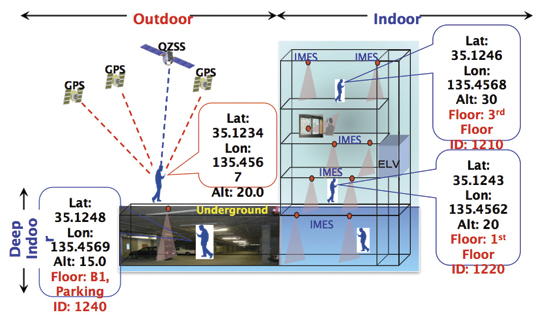
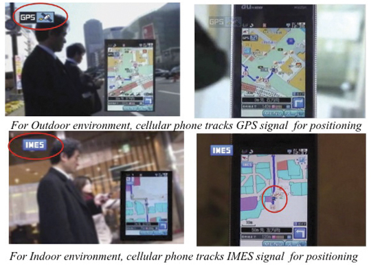
Figure 3 shows the concept of seamless position data using IMES, where the same receiver can be used both indoors and outdoors without interruption. GNSS satellites provide positioning and navigations outdoors, while IMES provides indoor navigation. Since the signal structures of GPS satellites and IMES is the same except for the navigation message contents, the same receiver can be used for both cases. Current GPS receivers will be capable of receiving IMES signals with modification of firmware only to decode the navigation message. Figure 3shows the concept of seamless 3D route guidance.
Figure 3. Seamless 3D route guidance using IMES.
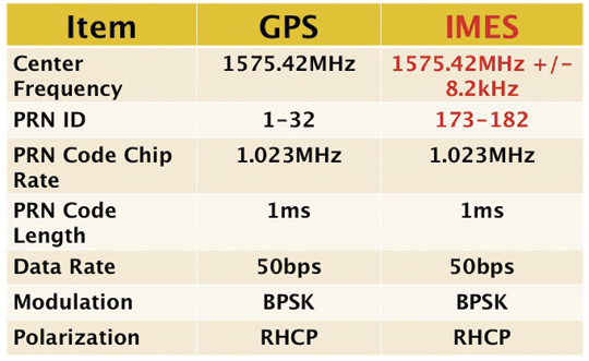
Signal Properties. The IMES signal is designed much like the GPS signal. It uses the same center frequency as GPS with an offset of +/– 8.2 kHz to minimize the possible interference from IMES to GPS signal. Ten PRN codes from 173 to 182 are assigned for IMES. These codes are provided by the U.S. government. Other signal-related parameters are the same as the GPS L1 C/A code signal. Table 3 shows IMES signal properties with respect to the GPS signal.
Table 3. IMES signal properties with respect to GPS.
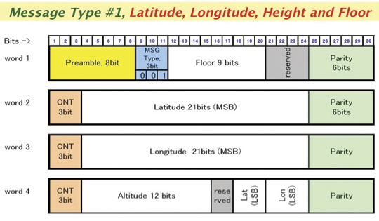
IMES has four different types of navigation message. The most significant is Type 1 as shown in Figure 4. It transmits latitude, longitude, height, and floor ID. The transmission of floor ID is a key factor for perfect 3D position data. Other message types are Type 0 (2-D position data with floor ID), Type 3 (short ID), and Type 4 (medium ID).
Figure 4. IMES Message type 1, 3D position, and floor
Interference Issue
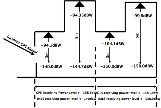
Since IMES shares the same frequency as GPS L1 band (1575.42 MHz), there is an interference level that IMES may have on GPS signals. This interference has been studied in detail by conducting experiments and simulations. Based on these studies and analysis, various methods have been considered to avoid harmful interference to GPS signal. To avoid such interference, IMES center frequency is shifted by +/– 8.2 Khz from GPS L1 band. This will have the least impact on the GPS L1 band signal. For example, if the IMES signal is –110 dBm (very strong) and the GPS signal is –142 dBm (very weak), the loss of GPS signal (C/N0) due to IMES is less than 2 dB. If the IMES signal is –120 dBm and the GPS signal is –142 dBm, there is no loss of GPS signal (C/N0). Based on this analysis, the IMES transmitter power must be controlled such that the maximum power to the receiver does not exceed –110 dBm at a distance of 3 meters from the transmitter. Figure 5 shows the guideline specified in the QZSS IS document for setting the transmitter effective isotropic radiated power (EIRP)based on location.
Figure 5. IMES transmitter power setup guideline in QZSS IS document.
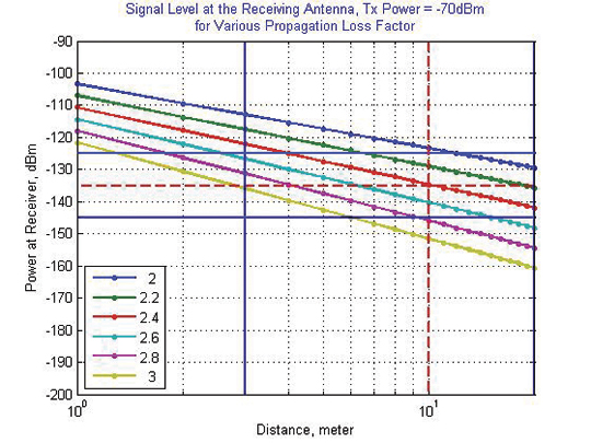
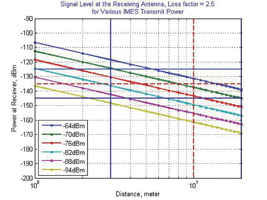
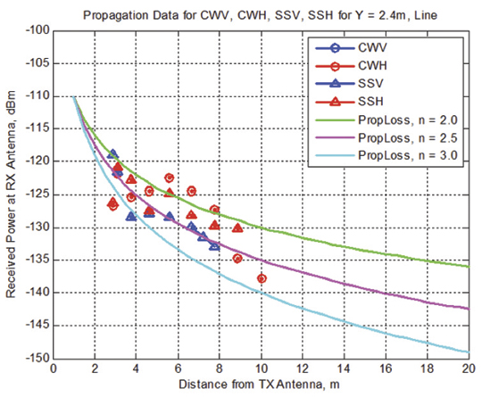
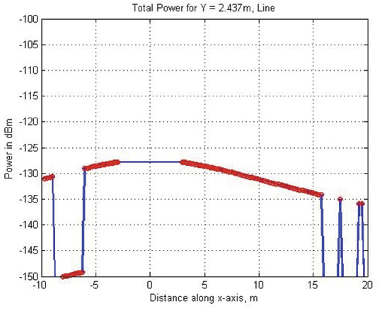
Figure 6 shows the signal propagation loss for transmitter power of –70 dBm for various propagation loss-factor values of n. Figure 7 shows path loss for various transmitter power for the same loss factor, n = 2.5. These graphs shows the maximum power that shall be used to cover an area without exceeding the maximum power level. If a single unit of IMES cannot cover the complete area, then multiple IMES units will be deployed to cover the entire area with suitable power level. These graphs serve as a guideline for setting transmitter power.
Figure 6. Signal path loss for –70 dBm signal for different path loss coefficient, n.Figure 7. Signal path loss for path loss coefficient, n = 2.5, for different transmitter power levels.
The signal propagation loss is calculated using the following equation; the gain of transmitter and receiver antennas is considered as unit gain (0 dB).
Hence, the equation depends on distance from the transmitter, d, and the propagation loss factor, n. The value of n is 2 for free space and increases for areas with objects that obstruct the signal. An office with soft partitions may use n = 2.5. The graphs can be used as a guideline to estimate the transmitter power to cover an area within the allowed power levels.
Application Areas
IMES can be used wherever indoor position data is required. It depends upon the application for that particular location as well. For example, an infrastructure-related safety application should have IMES installed at all elevators, escalators, staircases, emergency exits and routes, fire-fighting unit locations, and so on. Here are some of places where IMES might be used:
Every room of a building, to provide exact room location.
At entrances, exits, elevators, escalators, staircases, public facilities, and corridors for indoor navigation.
At every emergency exit for guidance.
Along hallways and lobbies at set intervals to guide the user.
In front of shops for advertising and information.
In sign posts to provide user’s location and guidance.
Complement other positioning systems like Wi-Fi, RF Tag, UWB, and so on.
As an indoor ground control point for surveying of large and multi-storey buildings.
With security cameras to provide accurate position data.
In factory production lines for automated control of moving objects.
Business Perspective
IMES technology was developed with the guiding concepts of low-cost global implementation and ease of installation and use. Low cost on the transmitter side is achieved by developing large-scale integratin (LSI) chips and IMES installation, setup, and database management tools. At the receiver side it is achieved by design of IMES signal so that existing GPS receivers in mobile phones, PDAs, or any other devices can use IMES by modifying only the firmware. The signal is designed so that it can adapt to other GNSS signals available in the future, for example, Galileo, QZSS, or Compass signals, requiring only firmware modification. Global implementation is made possible by signal design compatibility with existing GPS or GNSS signals. Ease of use is achieved again by signal design: one IMES transmitter can provide 3D position data, including floor information, with reliability and accuracy of a few meters even in deep indoor locations.
The development of IMES LSI chips (IMES transmitter) will also lead to development of value-added products for many consumer household appliances. For example, the green energy concept produced low-power LED lightbulbs. IMES chips can be installed in LED bulbs at very low additional cost. Similarly, it can be built in many other products like power socket devices, security devices, timing devices, and sensors where position data is also critical. This will provide an opportunity for the manufacturers to provide value-added products to users with indoor positioning devices. Not only electrical products but some construction materials or interior decoration materials like gypsum (dry
wall) boards can be made with built-in IMES chips. Installation of one piece of wallboard with an IMES built-in chip can provide position data in the room, reducing installation cost while not affecting the interior design of the room.
Implementation of IMES will also lead to new applications in the field of location-based services and applications where position data are necessary. It can also lead to new applications using IMES as an indoor electronic ground control point (GCP) in large buildings and indoor areas.
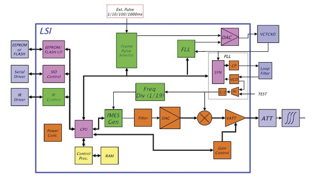
Chip Development. To reduce IMES transmitter cost, the IMES LSI chip has been developed and will be available by the end of the third quarter of 2011. This will reduce overall cost and size, and create platforms to develop value-added products integrating with other devices and systems. The chip is designed for global communications systems like personal handy-phone system (PHS, a mobile phone communication system developed in Japan), CDMA, and GSM. Figure 8 shows a block diagram of the chip transmitter.
The basic specifications of the LSI chip are: size, 12 x 12 millimeters; power, to be determined; maximum transmit power, –30 dBm or –60 dBm (user selectable); frequency, L1 band, 1575.4282 MHz or 1575.4118 MHz (user selectable); PRN codes, 173–182 (user selectable); signal type, GPS L1C/A, with upgrade capability to other GNSS signals.
Installation and Management
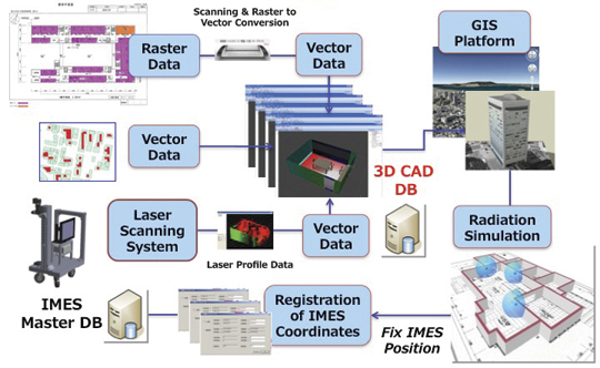
An IMES installation, setting, and management system has been developed to facilitate deployment. The main purpose of the system is to provide IMES transmitter position data (latitude, longitude, height) without conducting precision surveys, thus reducing installation, setting, and management costs. The system helps locate optimum locations for IMES transmitter siting, control transmitter EIRP power, set PRN IDs, and assign position data. The system can also use various types of map data sources to generate necessary floor data or indoor maps in 3D. The inputs can be either 3D vector data or 2D raster images, or even paper maps.
The overall system consists of four sub-systems:
IMES Setup Tool (ISET). This tool is used to set up the IMES transmitter. It provides two basic functions: to set up signal-related data (setting PRN code, transmitter power, navigation message rate, and so on) and to set up message-related data (position data, floor data, message types and their contents, message sequence, and so on). The R&D version of IMES also allows transmitting some special data for research and development purpose. It is possible to change the preamble value different from GPS, load a different PRN code table than IMES, change the navigation message data rate, generate a BOC(1,1) signal to test L1C-like signals, and change the RF frequency. The setup tool also has user-access management so that only authorized users can change certain sensitive data like PRN code, position data, and transmitter power.
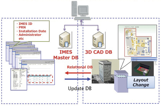
IMES Database Management Tool (IDBM). This tool simplifies installation and management by providing a necessary database including a building-related database, a service-provider database, a device-related database, other integrated sensors database (if any), and a signal-related database. Since IMES is controlled and managed, guaranteed and authorized services can be provided for dedicated applications. This enhances the reliability of an IMES-based positioning system for infrastructure, security, and safety-related applications.
3D Mapping Tool (IMAP). This tool, shown in Figure 9, provides a 3D map database for IMES either for implementation or end-user applications. The mapping tool can use 3D vector data (for example, existing DXF files), raster image data, or direct user input. A laser scanning system with CCD camera is used to generate 3D data if existing data is not available. The tool creates walls, windows, doors, ceilings and other smaller objects from the laser data. If data are available in paper drawings, they are scanned to create raster images before digitizing them into vector format.
Figure 9. 3D Map Database Development System.Figure 10. Concept of IMES database for implementation, setting and management.
The system will ultimately create a 3D database of a building at floor level that can be linked with external databases. Figure 10 shows the overall concept of the IMES database system that includes both IMES database and 3D map database. The two database systems are linked by a relational database system. Any update in the map database can be reflected into the IMES database.
Signal Propagation Loss Tool (IPMODEL). This tool simulates the signal level where IMES will be set up. It is necessary to have optimum deployment of the transmitter to cover the area as large as possible within the allowed power level. Although the allowed maximum EIRP power level is –64 dBm for Japan, the approach is always to use the least power possible to cover the area, to avoid any possible harmful interference to other systems as well as to limit the availability of the signal to only the desired area.
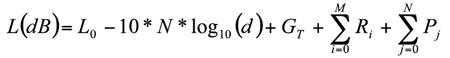
The following equation is used to calculate the signal path loss which is based on Frii’s free-space path-loss model.
GT is the transmitter antenna gain. The receiver antenna gain is assumed to have unit gain (0 dB) and hence not included in the model.
L0 is the power loss at 1 m distance and is given by 20 x log10(signal wavelength) — 20 x log10(4*pi).
N is the path-loss factor, which is 2 for free space, 2.5 for office room with soft partition, and 3.0 for rooms with hard partition.
Ri is loss due to i number of reflections by objects.
Pj is loss due to j number of penetrations through objects.
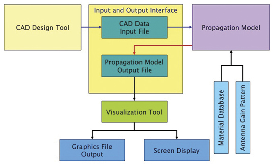
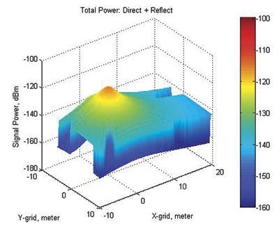
Figure 11 shows the propagation-loss tool flowchart. It uses 3D map database provided by the 3D mapping tool and database from the database management tool. It also uses antenna gain pattern and material electrical properties to compute the power loss due to reflection and penetration. Figure 12 shows the signal propagation output from the model for a building lobby. Figure 13 and Figure 14 show the output from the propagation loss results from the actual measurement and model output, respectively. The results match within a difference of few dBs.
Figure 11. Path Loss Tool flowchart.Figure 12. 3D view of signal power in a building lobby.Figure 13. Actual signal power measured at different locations in the lobby shown in Figure 12Figure 14. Signal power output from the propagation loss tool at the same location shown in Figure 13
Experiments and Demonstrations
Experiments and demonstrations have been conducted to validate the IMES concept, uses, and applications. Early experiments validated the
concept, message design, and interference analysis. Later experiments focused on actual implementation for infrastructure, and social-network and location-based applications. Pilot projects have been conducted in collaboration with the Japanese government to test IMES capabilities for seamless positioning and navigation and for social infrastructure platform.
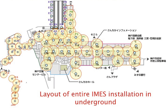
The Free Mobility Project in Kobe is the biggest social experiment using IMES for seamless navigation under the sponsorship by the Ministry of Land, Infrastructure, Transport, and Tourism. The project was conducted in an underground shopping mall of Kobe railway station. Shopping mall visitors were asked to participate in the navigation using IMES-capable mobile phones. Most visitors could follow the route they had chosen or find the destination point using the IMES set-up.
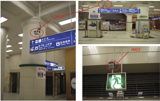
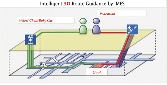
A total of 70 IMES transmitter units were installed at locations including ticket counters, elevator entrances, emergency exits, fire-extinguisher locations, staircases, station entrances, and alleys of the shopping mall. Figure 15 shows a part of the IMES transmitter location map. It covers one of the sections of the shopping mall. Figure 16 shows various locations where IMES transmitter devices were installed. As shown in Figure 17, intelligent 3D route guidance can be performed based on user preference. For example, a user in a wheelchair must be guided by a route that has no staircases, shown by green route in the figure, to reach the destination. A pedestrian can be guided by red route, which is the most direct route to the destination.
Figure 15. IMES transmitter location map to cover the underground shopping mall in Kobe Station.Figure 16. Installation of IMES near the station entrance and emergency exit.Figure 17. Intelligent 3D route guidance using IMES.Figure 18. Seamless navigation by mobile phone using GPS and IMES.
The distribution of each IMES transmitter is done in such a way that it covers a radial distance of 10 to 20 meters. The deployment density of IMES depends on the location environment. If an IMES device is located near the entrance, the coverage distance will be around 10 meters to minimize transmitted power. IMES devices in deep indoor locations can cover a radial distance of about 15 to 20 meters.
Commercially available mobile phones with a firmware update for IMES were used to receive the IMES position data. The phones also included the shopping mall and station map including related databases for various applications.
Conclusions
IMES can provide reliable and guaranteed 3D position accuracy, including floor information. IMES signal design is done in such a way that it can use existing as well future GPS/GNSS receivers without any hardware modifications. Necessary implementation, setup, and management tools are also developed to facilitate IMES installation and to minimize the cost so that large-scale global implementation is possible. IMES LSI chips are being developed for large-scale implementation. IMES will also help in developing many other location-based applications and services. IMES evaluation kits will soon be available for joint R&D projects.
IMES technology-related patents have been filed in Japan and many other countries. The basic patents have already been approved in Japan. GNSS Technologies invites academic institutions to participate in joint R&D projects.
Dinesh Manandhar is a visiting researcher at the University of Tokyo, where he received his Ph. D, and a senior researcher at GNSS Technologies Inc. He is one of the designers of IMES message structure and involved in developing indoor navigation system based on IMES for seamless navigation environment. He can be reached at [email protected].
Hideyuki Torimoto is the president of GNSS Technologies Inc. Japan. He established Trimble Navigation Japan and Weathernews Inc. in 1986. He also established the Research Forum on Social Infrastructure for Advanced Positioning (NPO) in 2003 and the Satellite Technology Laboratory in Tokyo University of Marine Science in 2004. He served as Satellite Division Member of ION for 2003-04. He can be reached at torimoto @ gnss.co.jp.
At the start of a new decade, let’s examine the state of the GNSS consumer market and technology. In the December 2009 issue of GPS World, I described the developments that put GPS in cell phones over the last decade. That technology revolution has brought GPS a very long way. Having come this far, we can ask that most famous of all navigation questions:
Are we there yet?
In this column, I focus on the question for the consumer segment of GNSS. Has the consumer market reached the point we expected it to be by now? Has the technology reached levels we anticipated?
The cell-phone GPS revolution began with the catalyst of U.S. E911 legislation, which mandated that when an emergency (911) call is made from a cell phone, the location of the cell phone must be provided. Among several competing location technologies, GPS proved to be the big winner, thanks to seven technology enablers: assisted GPS, massive parallel correlation, high sensitivity, coarse-time navigation, low TOW, host-based GPS, and RF-CMOS.
All of these together enable very low-cost implementation of GPS in cell phones, even phones on networks such as GSM and W-CDMA that do not have fine-time synchronization (that is, they are not precisely synchronized with the GPS system). GPS is now found in roughly 500 million phones in use today.
Four Milestones. From a consumer market perspective, we have exceeded forecasts. From a technology perspective, we have kept track with Moore’s law. Chips and receivers are cheaper than expected — because, as well as Moore’s law, we have seen greatly increased volumes and competition. Low-cost chips have not come at the expense of performance; in fact, the opposite — as chips have evolved, they have become less costly and better performing.
Small, cheap antennas have affected performance, but given the same antenna, I will demonstrate that a receiver with a single-die GPS chip costing less than $4 can outperform a $19,000 receiver.
This sounds paradoxical, even impossible — indeed many of you may be penning letters to the editor right now! But the time-to-first-fix, sensitivity, and urban-accuracy data will prove my point.
As a consequence of chip evolution, we are reaching plateaus of development for GPS-only systems. However, there remain many problems to solve, especially in urban canyons and indoors. These problems may never be solved with GPS alone, or with any single system alone. This decade will be characterized by GPS-plus; the days of GPS-only will soon recede into the past.
Don’t interpret this as a failing of GPS — quite the opposite. Because GPS-only systems have worked so well, they have found their way into half a billion cell phones, and we are boldly taking GPS to places no navigation has gone before. As we do, we start to encounter the limitations of GPS-only performance.
We will see the proliferation of GPS-plus: GPS+MEMS, GPS+Wi-Fi, GPS+NMR, and GPS+GLONASS, Compass, QZSS, and Galileo. The winners will be those with the greatest levels of integration. To paraphrase Winston Churchill, this is not the end of GPS, it is not even the beginning of the end. But it is, perhaps, the end of the beginning.
GNSS Consumer Market
For market forecasts made a few years ago, we can look at summaries provided in GNSS Markets and Applications, by Len Jacobson: a 2006 Frost & Sullivan report estimated the market for PNDs and handheld devices (not including cell phones) in 2010 would be $2.7 billion, with 8.3 million units, at an average selling price (ASP) of $325. In fact, this market today is approximately $6 billion, with 40 million units, at an ASP of $150.
Twice the Size. The consumer market, not including cell phones, is twice as big (in dollars) as forecast just a few years ago, even though prices are less than half forecast. Unit sales are more than four times forecast.
For the cell-phone market segment, in 1999 when the E911 rules were enacted in the United States, it was anticipated that A-GPS would be adopted only in fine-time (synchronized) networks, such as Verizon and Sprint CDMA. In coarse-time (non-synchronized) networks such as GSM, the expectation was that terrestrial wireless location techniques, such as time-difference-of-arrival (TDOA) and enhanced-offset-time-difference (E-OTD), would dominate. Today, only a few niches use TDOA, E-OTD is extinct, and GPS rules in coarse-time networks worldwide, including GSM in Europe and North America, and W-CDMA in Japan.
The consumer market, in particular the cell-phone market, has grown so rapidly that more receivers have been built in cell phones in the last three years than all other GPS built, ever. Today, L1 C/A-code GPS accounts for more than 99 percent of all GNSS receivers manufactured each year.
From a consumer market perspective, have we reached the point we expected to be by now?
Yes!
Not only have we arrived, we have far surpassed expectations.
GPS and Moore’s Law
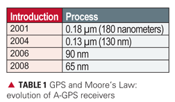
Moore’s law says that for a given number of transistors, the chip size will halve every two years. Table 1 shows what this looks like in practice. For a particular class of GPS chip, the A-GPS receiver with massive parallel correlation, it shows release dates of different generations of these chips, and the technology process, which is the linear dimension of a single gate on the silicon die. As this dimension reduces to 70 percent of the previous value, the 2-dimensonal chip size reduces by 2 times. You can see Moore’s law in action here: approximately every two years, the technology process moves to the next level, and the chip size reduces by 2X. People are now talking about GPS chips in 45 nanometers, the next step.
For a comparison, consider the Broadcom BCM 4751 chip, designed for cell phones. This chip is 2.9 X 3.1 millimeters, the size of the letter B on this page. This is a single-die host-based GPS/SBAS receiver, including RF front end, low-noise amplifier, baseband, and power management unit. Ten iterations of Moore’s law have passed in the last 20 years. The same chip, had it been built 20 years ago, would have been 210 times (a thousand times) bigger.
There were never chips that big. GPS chips aren’t just getting smaller with Moore’s law, they are getting vastly more complex and more capable.
Performance
At an elemental level, a GPS receiver does just three things: it starts, it tracks weak signals, and it computes position, velocity, and time. Strip away the obfuscating details, and performance may be summed up by: how fast, how sensitive, how accurate.
Since the 1990s, time to first fix ( TTFF) and sensitivity have improved dramatically, thanks to the seven technology enablers discussed earlier. TTFF for assisted cold starts, or unassisted warm starts, is now as good as one second, even without fine-time. This is a 45X improvement on typical GPS performance of the 1990s. Sensitivity increased roughly 30X (to -150 dBm) in 1998, then another 10X, (to -160 dBm) in 2006, and perhaps another three times to date, for a total of almost 1,000X extra sensitivity.
What about accuracy?
Some perceive low-cost chips as synonymous with low accuracy. This is not true. It is true that small, cheap antennas reduce accuracy; but given the same antennas, the lowest cost receivers on the market today will outperform the most expensive in typical environments where cell phones are used. The following figures show data to prove this point.
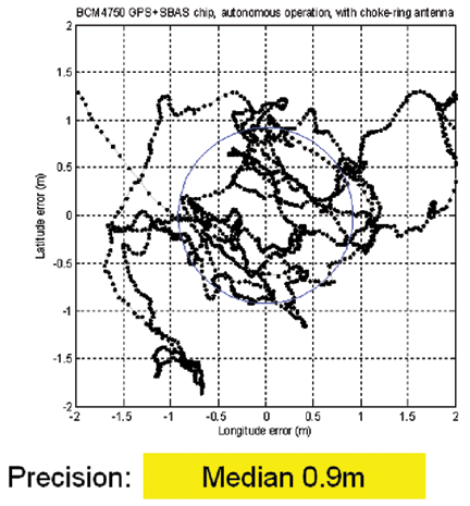
First we connect one of the smallest, lowest cost GPS receivers t
o one of the best antennas, a choke ring, on a rooftop with a clear view of the sky. Figure 1 shows the scatter of positions. The blue circle shows the median distribution, which is 0.9 meters for this dataset of 2000 fixes.
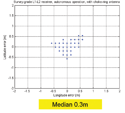
FIGURE 1a. Low-cost GPS with large, rooftop antenna.FIGURE 1b. Survey-grade GPS with large, rooftop antenna.
The adjacent plot shows the positions obtained from a $19,000 survey-grade GPS receiver, connected to the same antenna. The survey-grade GPS, with a median distribution of 0.3 meters, shows a 60-centimeter advantage over the cell-phone GPS, or maybe a 3X advantage depending on how you look at it. But don’t get too hung up on this result, because this is neither the typical consumer scenario (on a rooftop with choke-ring antenna), nor the main challenge facing us today.
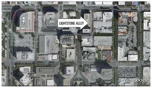
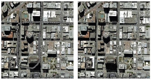
Next we look at the accuracy achieved with a more typical consumer antenna, in a more typical environment. Figure 2 shows the positions obtained in downtown San Jose with an active patch antenna, such as found in PNDs. San Jose is a fairly typical U.S. city, not the hardest place to use GPS, but not the easiest either. Lightstone Alley, adjacent to tall buildings, is only five meters wide.
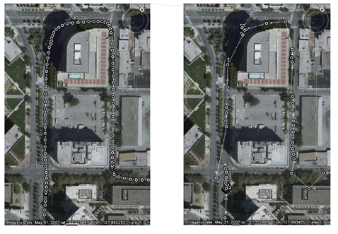
FIGURE 2. Performance of cell-phone GPS (white) versus truth-reference system (blue). Median accuracy 4.4 meters, 67 percent 5.6 meters, 95 percent 11.2 meters.
To evaluate accuracy we used a truth-reference system combining GPS and a tactical-grade IMU with ring laser gyro to produce the blue dots on the figure. The white dots are the low-cost GPS positions. Most of the time, the white dots appear to be on top of the blue, but occasionally you see some separation, and there the red lines show the horizontal error. The median horizontal error is 4.4 meters.
Figure 3 shows the comparison of low- and high-cost receivers, with the survey-grade receiver connected to the same patch antenna as the cell-phone GPS. There are many position gaps from the survey-grade receiver, and the position walks around when the vehicle is stationary (at the intersections, bottom left and top of the figure). This is because of the weak signals available in the urban environment. But don’t get too hung up on this result either, since we are still not at the real challenge of consumer GPS: location in severe urban canyons, such as San Francisco, New York, Chicago, Shanghai, Taipei, Shinjuku, and similar. In these, typically, only one or two GPS satellites can be seen directly. Other satellites may be tracked, but only by observing purely reflected signals. This is not classic GPS multipath, the combination of a direct and reflected signal; instead this is the combination of nothing but reflected signals. The direct signals are usually completely blocked by many buildings, and are not observable at all. So the whole premise of GPS — observing range from time of flight — breaks down, and it is very difficult to get good accuracy.
FIGURE 3. Comparison of cell-phone (left) and survey (right) receivers, both with patch antenna
Figure 4 compares the cell-phone GPS with the survey-grade GPS, connected to the same small antenna, under such circumstances in San Francisco’s Financial District. There are no fixes at all from the survey-grade receiver. Why?
FIGURE 4. Cell-phone (left) and survey (right) receivers, in severe urban canyon
In Montgomery Street, there was only one directly visible satellite, with a signal strength of -132 dBm. All the other satellites were at -140 dBm or weaker, and traditional GPS receivers cannot acquire signals at this level. Hence the only receivers that work in this environment are modern high-sensitivity receivers most commonly found in cell phones.
You can see that the move to lower-cost receivers has not come at the expense of performance. In fact, the opposite: TTFF and sensitivity have improved dramatically, while accuracy has not been compromised, and is in fact much better in urban environments than legacy receivers, and even modern survey-grade receivers.
But are we there yet?
Although the consumer GPS market has irrefutably arrived, from a technical perspective the answer is more nuanced. Consumer GPS technology has made tremendous leaps forward. But precisely because of these improvements, we are taking GPS where it was never expected to go. It is no longer enough for GPS to work indoors (which it can). The demand is now for it to work as well as if it were outdoors (which, presently, it cannot).
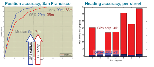
Performance improvements seen with GPS-only will almost certainly not continue at the recent rate. We do not anticipate yet another 45X improvement in TTFF, or another 30 dB of sensitivity, for GPS alone. However, we do expect order-of-magnitude performance increases with the addition of other technologies. Figure 5 shows data from a TomTom 950, a GPS+MEMS containing the same GPS chip used in the earlier tests, MEMS accelerometers, and MEMS rate gyros. When tightly integrated and tested in the same deep urban canyons of San Francisco, the effect on position is good: median accuracy improved by 30 percent, worst-case errors are more than halved. But the result on heading accuracy is especially dramatic.
FIGURE 5. PND position accuracy (left), and heading accuracy (right), San Francisco
The bar graph shows the worst-case heading accuracy in each street. With GPS-only (red), the worst-case error is around 45 degrees, a familiar result to anyone who has used any GPS-only device in a similar environment: sooner or later the map will veer erroneously. However, with the integration of the MEMS rate gyros (blue), the worst-case heading errors drop to around 3 degrees, a 15X improvement in a key metric, similar to the improvements of the last decade, but now thanks to the effect of GPS-plus.
We will soon see GPS-plus many other technologies: Wi-Fi, NMR/MRL (power measurements from GSM and 3G phones), and of course GPS+GLONASS, Compass, QZSS, and Galileo. Because many mobile devices now include GPS, Wi-Fi, and 3G, there is a natural path for the evolution of GPS technology to include Wi-Fi and MRL measurements.
There is a also natural trend to source different radios from the same chip supplier. After all, why would you wish to undertake a do-it-yourself effort at removing co-existence issues in different radios, when a chip supplier has already done it for you?
Looking forward, it is very likely that this new decade will be characterized by GPS-plus other technologies, and the winners will be those with the greatest levels of integration.
Frank van Diggelen is senior technical director of GPS systems and chief navigation officer for Broadcom Corporation. He holds more than 45 U.S. patents, has a Ph.D. in electrical engineering from Cambridge University, and is the author of A-GPS: Assisted GPS, GNSS & SBAS.
Federal Communications Commission chairman Kevin Martin plans to issue new rules for testing location-based E911 service, as well as a call for public comment on the technology itself. The FCC chair plans to rule soon that testing of location-based enhanced 911 wireless accuracy be conducted at local emergency call centers rather than at the state level. The Association of Public Safety Communications Officials International petitioned the FCC for such a move several years ago.
APCO will soon release its Project LOCATE (Locate Our Citizens in Times of Emergencies) report. The report studied the accuracy of location information that public safety answering points get from 911 calls made from wireless phones.
Martin plans to seek public comment on E911 technological advances and prospects for an across-the-board industry deployment of a hybrid approach to E911, which draws on both GPS technology in handsets as well as network triangulation techniques.
The Global Positioning System has provided more than a few ironies in its relatively short existence: A system so accurate that, until last year, government policy required operators to degrade the quality of the open C/A-code signal. A navigation instrument more accurate than the maps across which navigators plotted their courses. Early GPS-based car guidance systems that displayed vehicle location in the middle of buildings or lakes.
But, as with so many other aspects of daily life, what may have seemed funny before September 11 is no longer a laughing matter..
The need for a better correspondence of location information is underscored by the urgency being given to the Federal Communications Commission’s (FCC’s) five-year-old mandate for enhanced 911 (E911) services. E911 provides mobile telephone users with the same automatic location information (ALI) of emergency calls now en-joyed by users of wireline phones at fixed sites. The benefits of ALI for getting police, firefighters, and ambulances to an emergency quickly are obvious..
The first phase of E911 implementation — identifying the nearest cell site from which a call comes — only covers less than half of the U.S. population. Implementation of Phase II, which requires much more accurate real-time positioning, was scheduled to begin October 1. Last month, however, the FCC granted extensions to five national wireless carriers for initiating their Phase II plans. The agency still expects carriers to provide all mobile phone users with E911 coverage by the end of 2005..
Three wireless carriers will employ handset-based assisted-GPS techniques in providing ALI that must be twice as accurate (50 meters versus 100 meters) as the “network-based” positioning that the other carriers have selected. (This should prove interesting in the marketplace. Because the E911 capability imposes no direct cost on customers, why would consumers choose non-GPS equipment and carriers offering substantially less accurate service?).
Little of the E911 delay stems from unavailability of GPS technology. Upgrading software at switching servers is the primary cause for postponements sought for handset-based systems. Even with the lower accuracy standards, however, carriers with network-based solutions pleaded for more time to get their positioning technology to work..
After the communications and positioning kinks are worked out of the E911 systems, public safety and commercial location-based service providers will still face an operational dilemma. That is the mismatch between positioning techniques and mapbases and differences among maps discussed earlier. Cartographers have long understood that variations among coordinate systems and datums can make the same latitude/longitude mean different things to different people. But until GPS came along, navigation and tracking techniques were so much cruder that such cartographic variations disappeared inside the error ellipse of the positioning systems..
Under Phase II, emergency call centers (public safety answering points or PSAPs, in FCC parlance), public safety agencies, and E911 callers need to be on the same page. Use of proprietary mapbases with incompatible grid designs in either paper or electronic format is a recipe for disaster. It will create coverage ambiguities near PSAP boundaries (Which agency should handle the call?) and lead rescuers tens or even hundreds of meters away from injured or imperiled callers. Yet a distinctive reference grid seems like a much less important proprietary feature for competing map vendors than the other information and cartographic design built into their products..
The Public X-Y Mapping Project has proposed one solution to this mishmash of maps: adoption of a U.S. National Grid (USNG) for Spatial Addressing. The USNG would effectively match up with the Military Grid Reference System (MGRS), taking advantage of that public domain systemyy?s use of the Universal Transverse Mercator (UTM) grid. MGRS is one of the most common datums residing within GPS receivers and could be made the default mode for E911 calls, according to Jules McNeff, one of the mapping project’s principals and a well-known GPS advocate.
Agreement between civilian and military mapping standards in these days of homeland security concerns probably wouldn’t be a bad idea. And the benefits, of course, would carry over into the commercial realm of value-added location-based services, too..
The interagency Federal Geographic Data Committee’s standards working group recently recommended adoption of USNG as a preferred national standard. “Effective implementation of USNG on maps and in GPS receivers is the single most important thing [that we] can do to improve emergency response operations nationwide almost immediately,” says McNeff. Readers interested in exploring the USNG proposal can find more details on-line at and.
Whether it’s USNG or another universal reference system, GPS manufacturers, public safety agencies, commercial service providers, mapmakers, and the general public have a common interest in achieving a GPS-friendly national spatial standard.