Tag: GNSS signal

  • GNSS Spoofing Detection: Guard against automated ground vehicle attacks

    GNSS Spoofing Detection: Guard against automated ground vehicle attacks

    Read Richard Langley’s introduction column, Innovation Insights: What is a carrier phase?


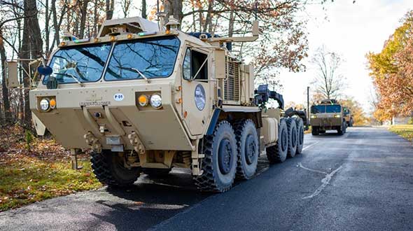
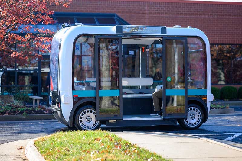
    An approach for ground vehicles using carrier-phase and inertial measurement data

    The combination of easily accessible low-cost GNSS spoofers and the emergence of increasingly automated GNSS-reliant ground vehicles prompts a need for fast and reliable GNSS spoofing detection. To underscore this point, Regulus Cyber, an Israeli cybersecurity company, recently spoofed a Tesla Model 3 on autopilot mode, causing the vehicle to suddenly slow and unexpectedly veer off the main road.

    Among GNSS signal authentication techniques, signal-quality monitoring (SQM) and multi-antenna could be considered for implementation on ground vehicles. However, SQM tends to perform poorly on dynamic platforms in urban areas where strong multipath and in-band noise are common, and multi-antenna spoofing detection techniques, while effective, are disfavored by automotive manufacturers seeking to reduce vehicle cost and aerodynamic drag. Thus, there is a need for a single-antenna GNSS spoofing detection technique that performs well on ground vehicles, despite the adverse signal-propagation conditions in an urban environment.

    In a concurrent trend, increasingly automated ground vehicles demand ever-stricter lateral positioning to ensure safety of operation. An influential study calls for lateral positioning better than 20 centimeters on freeways and better than 10 centimeters on local streets (both at a 95% probability level). Such stringent requirements can be met by referencing lidar and camera measurements to a local high-definition map, but poor weather (heavy rain, dense fog or snowy whiteout) can render this technique unavailable.

    On the other hand, progress in precise (decimeter-level) GNSS-based ground vehicle positioning, which is impervious to poor weather, has demonstrated surprisingly high (above 97%) solution availability in urban areas. This technique is based on carrier-phase differential GNSS (CDGNSS) positioning, which exploits GNSS carrier-phase measurements having millimeter-level precision but integer-wavelength ambiguities.

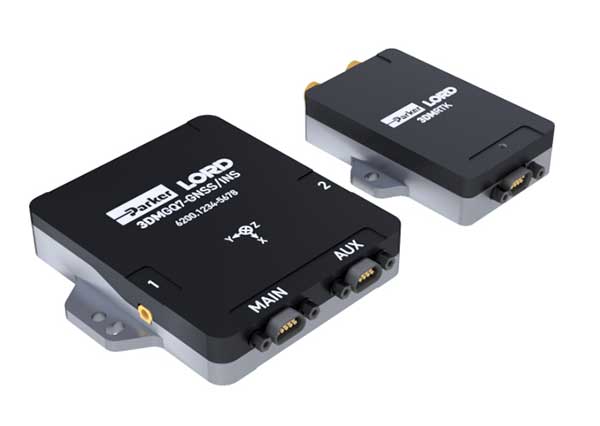
    Key to our promising results is the tight coupling of CDGNSS and inertial measurement unit (IMU) data, without which high-accuracy CDGNSS solution availability is significantly reduced due to pervasive signal blockage and multipath in urban areas. Tight coupling brings millimeter-precise GNSS carrier-phase measurements into correspondence with high-sensitivity and high-frequency inertial sensing. Our particular estimation architecture incorporates inertial sensing via model replacement, in which the estimator’s propagation step relies on bias-compensated acceleration and angular rate measurements from the IMU instead of a vehicle dynamics model.

    As a consequence, at each measurement update, an a priori antenna position is available whose delta from the previous measurement update accounts for all vehicle motion sensed by the IMU, including small-amplitude high-frequency motion caused by road irregularities. Remarkably, when tracking authentic GNSS signals in a clean (open-sky) environment, the GNSS carrier-phase predicted by the a priori antenna position and the actual measured carrier phase agree to within millimeters.

    The research described in this article pursues a novel GNSS spoofing-detection technique based on a simple but consequential observation: it is practically impossible for a spoofer to create a false ensemble of GNSS signals whose carrier-phase variations, when received through the antenna of a target ground vehicle, track the phase values predicted by inertial sensing. In other words, antenna motion caused by factors such as road irregularities or rapid braking or steering is sensed with high fidelity by an onboard IMU but is unpredictable at the sub-centimeter-level by a would-be spoofer.

    Therefore, the differences between IMU-predicted and measured carrier-phase values offer the basis for an exquisitely sensitive GNSS spoofing-detection statistic. What is more, such carrier-phase fixed-ambiguity residual cost is generated as a byproduct of tightly coupled inertial-CDGNSS vehicle position estimation.

    Two difficulties complicate the use of fixed-ambiguity residual cost for spoofing detection. First is the integer-ambiguous nature of the carrier-phase measurement, which causes the post-integer-fix residual cost to equal not the difference between the measured and predicted carrier phases (as would be the case for a typical residual), but rather modulo an integer number of carrier wavelengths. Such integer folding complicates development of a probability distribution for a detection test statistic based on carrier-phase fixed-ambiguity residual cost.

    Second, the severe signal multipath conditions in urban areas create thick tails in any detection statistic based on carrier-phase measurements. Setting a detection threshold high enough to avoid false spoofing alarms caused by mere multipath could render the detection test insensitive to dangerous forms of spoofing. Reducing false alarms by accurately modeling the effect of a particular urban multipath environment on the detection statistic would be a Sisyphean undertaking, requiring exceptionally accurate up-to-date 3D models of the urban landscape, including materials properties.

    Our work takes an empirical approach to these difficulties. It does not attempt to develop a theoretical model to delineate the effects of integer folding or multipath on its proposed carrier-phase fixed-ambiguity residual cost-based detection statistic. Rather, it develops null-hypothesis empirical distributions for the statistic in both shallow and deep urban areas, and uses these distributions to demonstrate that high-sensitivity spoofing detection is possible despite integer folding and urban multipath.

  • Innovation Insights: What is carrier phase?

    Innovation Insights: What is carrier phase?

    Innovation Insights with Richard Langley
    Innovation Insights with Richard Langley

    WHAT IS CARRIER PHASE? The obvious answer is: the phase of the carrier. But this is not helpful if you don’t know what a carrier is. A carrier is basically a harmonic electromagnetic wave — a pure continuous sinusoidal wave with a single constant frequency and amplitude.

    Such a wave has limited uses. However, if we modulate or change the characteristics of the wave in some way, then the wave can carry information. Changing the amplitude by using a voice or music audio signal is amplitude modulation as used for AM radio.

    Instead, one could modulate a carrier by changing its instantaneous frequency, which is frequency modulation or FM and is used for high-fidelity broadcasting. Yet another way to modulate a carrier is to change the instantaneous phase of the carrier, and that is how GNSS works.

    GNSS carriers are phase-modulated by pseudorandom noise (PRN) codes and navigation messages. A GNSS receiver uses the PRN codes to produce the pseudorange observable with a precision in the tens of decimeter range. This is the most common observable for GNSS positioning.

    But by stripping away the modulation of the received GNSS signals, the receiver can measure the phase of the underlying carrier. Changes in carrier phase over time reflect the change in the (pseudo)range but are about two orders of magnitude more precise.

    One problem with carrier-phase measurements is that they have an initial cycle ambiguity that must be resolved, preferentially fixed to the correct integer value, before they can be used for positioning, but this can be achieved without too much difficulty. While fixing the ambiguity of carrier-phase measurements might be considered a nuisance in GNSS positioning, it can help detect spoofing of GNSS signals where some other techniques might fall short.

    In this “Innovation” column, we look at how carrier-phase measurements combined with those from an inertial measurement unit can guard against a deliberate attack on an automated ground vehicle — something that cannot be discounted in our world these days.

    Read the full “Innovation” column: GNSS Spoofing Detection: Guard against automated ground vehicle attacks.

  • How to select an INS for mobile mapping

    How to select an INS for mobile mapping

    Image: OxTS
    Image: OxTS

    OxTS has shared this piece on OxTS.com.

    Mobile mapping is helping accelerate the progression of some of the most difficult engineering challenges on the planet, including those around autonomous driving and advanced surveying techniques, such as lidar.

    The complexity of those challenges means that the outputs from a mobile mapping inertial navigation system (INS) must be as accurate as possible. A high-performing INS will make the most of any available GNSS signals, with the aim of providing centimeter-level accuracy even in areas where GNSS performs poorly, for instance in urban canyons. It also offers important data on pitch, roll and heading, which maintains the integrity of survey data even as the vehicle moves across large areas.

    With such a wide variety of INS devices on the market, it can be difficult to narrow down the best option. It is important to establish criteria that will aid in evaluating the different INS propositions out there for mobile mapping projects.

    Image: OxTS
    Image: OxTS

    1) How tightly integrated are the inertial measurement unit (IMU) and GNSS data?

    INS is an essential element in providing accurate location data in as many environments as possible. Therefore, it is important to know how effectively the data from the IMU supports the GNSS data. In technical terms, this means evaluating whether the sensors are tightly integrated at all, and if so, how well.

    The reason GNSS struggles in urban canyons and under tree canopies is that it is unable to get the six satellite signals necessary for a real-time kinematic (RTK) lock. In this situation, the GNSS will give readings that may be incorrect, as it is essentially trying to solve an equation without having all the numbers.

    A tightly integrated GNSS and INS data stream will select the most reliable signals and use those to determine the position of the vehicle. If the data streams are not tightly integrated, then the INS’ ability to counteract GNSS issues is limited. Without accurate positioning, data scans will lose accuracy and even become completely incoherent the longer the user scans — making them unreliable at best, and unusable at worst.

    2) Trading off accuracy and cost

    Although accuracy is vital in mobile mapping, some INS devices will provide data that is far more accurate than the given job requires. Because greater accuracy equals greater cost, users may be paying more than necessary.

    With that being said, the scale of accuracy and cost is not linear. An INS half the price of the most expensive one on the market will not be half as accurate. Look at each offering carefully to see what it includes and decide what level of accuracy and features are vital to the task. Eliminating unnecessary levels of precision or additional software features that are not needed is an effective way to make some savings.

    3) How rugged is the device?

    Mobile mapping vehicles will likely be out in the dry, wet, hot, cold, mud and snow. These vehicles will almost certainly be used consistently for long periods of time. Thus, it is essential to know that none of these conditions will stop the INS from working at peak effectiveness. Look for the IP rating (IP65 is essential for being weatherproof and protecting against shocks and dust) and ask what the average lifespan of the product is.

    Image: OxTS
    Image: OxTS

    4) Can the device be properly calibrated?

    Any INS is only as good as its calibration. Without calibration, the sensors in any INS can become misaligned and therefore provide inaccurate readings. Talk to vendors about their calibration processes — do they work to a nationally recognized standard of calibration like ISO 17025? Do their calibrations account for variations in temperature or humidity?

    It is also worth considering how often sensors need recalibration. Recalibration is a chargeable service from most vendors, meaning the more the device needs recalibrating, the more the user will have to pay. This could also lead to delays if the user must send units abroad to have them recalibrated.

  • Ultra-wideband brings signals indoors

    Ultra-wideband brings signals indoors

    Other sources, such as lidar, can be used to aid navigation in the absence of GNSS signals. (Photo: OxTS)
    Other sources, such as lidar, can be used to aid navigation in the absence of GNSS signals. (Photo: OxTS)

    We discussed complementary PNT with Peter Rylands, senior product manager at OxTS.

    What are some of the most promising approaches to complementary PNT and how does simulation technology help?

    There are two approaches of particular interest. The first is looking at LEO satellite systems that can provide supplementary and potentially more secure methods of navigation, with global coverage from a single system. But these will still suffer from some of the issues GNSS systems experience, namely, what happens when you can’t obtain a signal?

    The second is the use of visual aiding through sensor fusion, such as lidar and cameras, that can provide relative positioning (or absolute positioning once you have a space mapped) using SLAM algorithms. While this may increase onboard hardware dependencies, it creates a localized navigation system that can be better protected from malicious actors.

    In contrast, closed-loop systems can look to an infrastructure-based system, allowing free movement within the specific area in which the infrastructure is located and a potentially more reliable source of PNT, especially indoors, where GNSS is not available. Ultra-wideband is definitely the up-and-coming technology here, but systems using Wi-Fi, cameras, Bluetooth and others also are being used.

    Simulation, as within many domains, allows users to test on a large scale with fewer barriers to entry than real-world testing and an ease in making iterative changes to find an optimal solution. Whether that is to benchmark performance in locations of interest or to change configuration settings to improve visibility or positioning, simulation allows you to do this without the expense of going straight into the environment itself or configuring the actual vehicle under test.

    How does OxTS fit in that mix?

    OxTS provides customers with the ability to navigate anywhere; whether for reference data in R&D, georeferencing for survey and mapping, or active navigation of autonomous solutions. To do this we provide an IMU-first offering that we then complement with other technologies. Traditionally, this is with GNSS, to form an INS that can provide centimeter-level accuracy. However, we are also aware of the vulnerabilities of GNSS. For us, this is when it becomes an unreliable source of PNT in denied areas, such as indoors, in urban canyons or under tree canopies.

    Because of this, we are also investigating and developing complementary solutions that can enhance our offering for users who need confidence in their position even when GNSS is not available. Whether that is through sensor fusion, our Pozyx UWB solution for indoor navigation or other proprietary software and firmware capabilities.

    What kinds of complementary PNT are most useful in addressing specifically the challenges posed by jamming and spoofing and how does simulation help?

    We need to look at systems that cannot be impacted by, or have mitigations from, the impact of jamming and spoofing. Solutions that are independent of radio communications or satellite use are then valuable in providing this layer of protection. This is where we could look toward OxTS’s use of IMU technology and visual aiding systems. Simulation technologies would then allow you to run hardware-in-the-loop testing, where the primary GNSS solution can have simulated jamming and spoofing to understand the performance of your complementary and protected systems when GNSS cannot be trusted.

  • MGUE Increment 2 contracts awarded to BAE, L3 and Raytheon

    MGUE Increment 2 contracts awarded to BAE, L3 and Raytheon

    The United States Space Force’s Space and Missile Systems Center awarded the Military Global Positioning System User Equipment (MGUE) Increment (Inc) 2 Miniature Serial Interface (MSI) with Next-Generation Application Specific Integrated Circuit (ASIC) to BAE Navigation & Sensor System, L3 Technologies (now L3Harris) and Raytheon Technologies.

    According to the U.S. Space Force, the three MSI contracts are valued at $552 million and will be executed as Middle Tier Acquisition rapid prototyping efforts. The first delivery is scheduled for early fiscal year 2026.

    Enhanced processing and security features associated with M-code drove the decision to develop a smaller and more powerful receiver card for handheld and dismounted applications, the U.S. Space Force said. The MSI with Next-Generation ASIC will enable Military-Code GPS receiver production, mitigating the obsolescence issue of current ASICs and providing significant security and performance improvements for GPS-enabled weapons systems. MGUE Inc 2 will be compatible with all existing and future spacecraft and ground systems, it added.

    MGUE Inc 2 enables military GPS user equipment to receive allied GNSS positioning, navigation and timing (PNT) signals to increase both the resilience and capability of military PNT equipment, and deter attacks on GPS, the U.S. Space Force said. These signals will supplement GPS-based PNT in accordance with Department of Defense policies regarding usage of allied GNSS signals, ensuring identification and mitigation of cyber risks, and compatibility with existing PNT equipment.


    Feature photo: EvgeniyShkolenko/iStock / Getty Images Plus/Getty Images

  • Resilient PNT critical to maritime advancement

    Resilient PNT critical to maritime advancement

    The ROSS project, conducted in France by companies Marlink and SeaOwl, demonstrated the feasilibity of autononmous shipping. Orolia systems ensured resilient PNT. (Photo: Marlink)
    The ROSS project, conducted in France by companies Marlink and SeaOwl, demonstrated the feasibility of autonomous shipping. Orolia systems ensured resilient PNT. (Photo: Marlink)

    The International Maritime Organization (IMO) has issued a resolution for maritime cyber-risk management, effective January 2021. IMO Resolution MSC.428(98) affirms that maritime operators need to address cyber threats that risk the integrity and availability of technology systems.

    GPS/GNSS signal jamming and spoofing expose the vulnerabilities of PNT-reliant systems. The single point of failure in the signals used to synchronize military operations or determine a vessel’s location leaves maritime systems open to attack. With resilient PNT, maritime and naval vessels can rely on trusted data.

    Remote Operations at Sea. In September, Orolia participated in a Remotely Operated Service at Sea (ROSS) demonstration where an unmanned vessel was tele-operated from more than 800 kilometers (500 miles) away.

    With its SecureSync Interference Detection and Mitigation (IDM) suite, Orolia provided the project’s PNT cybersecurity package and delivered precise, reliable data for the control center to pilot the vessel from afar. The IDM suite includes GNSS threat detection and mitigation, as well as the option to include encrypted and alternative signals for use in GNSS-denied environments.

    After this successful demonstration, SeaOwl Group, the company leading the ROSS project, obtained the first remotely operated vessel navigation license in France.

    Diving Deep. Atomic clocks and oscillators are useful for underwater operations where RF signals are unavailable to provide accurate PNT data. Precision timing technologies, such as Orolia’s Spectratime mRO-50 oscillator, ensure stable timing for navigation systems through radar. They support missions such as:

    • stabilizing and synchronizing sensor measurement data collection for autonomous underwater vehicles (AUVs)
    • providing holdover to maintain precise positioning on submarines during extended periods of GNSS signal denial
    • generating precise frequencies with low phase noise and less burden on radio receiver architecture, such as search-and-rescue control centers
    • operating with low power consumption and increasing the reliability of radio reception.

    Resilient PNT is essential at sea, from military missions and commercial freight shipping to port management, search and rescue, research and fishing operations. Jamming and spoofing detection, threat mitigation, and alternative PNT sources configured in multiple layers of protection can ensure continuous operations, even in compromised environments. In shallow or deep-water environments, Orolia’s portfolio includes critical infrastructure support for naval command-and-control centers, essential GNSS vulnerability testing and services, and wearable solutions that fit in the palm of a hand.

  • GNSS simulator companies help pilots find their way

    GNSS simulator companies help pilots find their way

    Flight simulators range in price from free to tens of millions of dollars and in purpose from pure entertainment to serious business — such as learning to fly multi-million-dollar aircraft without crashing them in real life and getting anyone killed. Military and commercial pilots spend thousands of hours in simulators learning both routine operations and how to deal with emergency situations. They can become fully proficient through immersive training in these virtual environments. The U.S. Army, Air Force, Navy and Marines all use flight simulators to train pilots to fly in battle, recover in an emergency, and coordinate air support with ground operations. To do this, they use hardware and software developed both by military agencies and by commercial military contractors.

    In high-end flight simulators, the trainee steps into a life-size replica of a cockpit, whereas others consist of several monitors that cover the trainee’s field of view, or, at the lowest end, everything is crammed onto a single monitor. All flight simulators, however, are designed to replicate as closely as possible the layout and controls of a real aircraft. (Ironically, the $120 Microsoft Flight Simulator Premium Deluxe Edition lets you fly 35 different planes, while flight simulators that cost tens of millions of dollars are limited to a few models because they have to physically replicate the cockpit layout, which varies from aircraft to aircraft. Some training centers invest in multiple simulators, while others privilege convenience over accuracy and use a single simulator model.)

    Most professional flight simulators sit on top of either an electronically-controlled motion base or a hydraulic lift system that rotates the replica cockpit in three dimensions in reaction to both user input and simulated events. This provides trainees with haptic feedback, in other words, feedback they can feel. (Another example of a device that provides haptic feedback is a joystick with force feedback.)

    Like when learning to sail offshore or to survive in the wilderness, a large component of any pilot training program is navigation. For flight simulators, this involves detailed aeronautical charts, huge amounts of Earth observation imagery including thousands of airports, and faithful replicas of several cockpit navigation instruments. While aviation programs provide standard training to ensure pilots can handle situations ranging from enemy fighters to bird strikes to engine failure, they may overlook the importance of duplicating actual cockpit instruments rather than relying on facsimile ones.

    Simulating GNSS signals

    This is where GNSS simulators come into play. They make it possible “to simulate the actual GPS signal required by the cockpit navigation instruments,” according to a case study by Orolia.

    This approach, the company points out, offers advantages to both the trainees who use flight simulators and the engineers who develop them. For a trainee, “the advantage is that he is trained using the identical instruments as those in the actual airplane […] providing the same feedback as a real-world experience.” For an engineer developing a flight simulator, GNSS simulators make it possible to “design more effective flight simulation programs without compromising quality.”

    Furthermore, “using real navigation instruments may […] reveal unexpected behavior from the instrument, which helps the pilot to be prepared for this possibility. If any conditions involving the plane dynamics are not properly handled by the navigation unit, the pilot can obtain actual feedback from real navigation instruments, which could differ from feedback provided by a facsimile instrument.”

    Hardware-in-the-loop (HWIL) techniques enable Orolia to integrate its simulator in a flight simulator to reproduce the GPS/GNSS dynamics for the airplane in real time. “Because the pilot steers the aircraft in real time, the GPS simulator must also simulate GPS signals in real time, forming an HWIL integration,” the company said. “This integration enables the flight simulator to integrate the actual navigation unit to provide a very realistic environment for the trainee.”

    Racelogic, another manufacturer of GNSS simulators, is launching a new RealTime LabSat that can connect to Microsoft Flight Simulator, including the new 2020 version. “This will create a live GNSS RF feed that accurately follows the trajectory in the simulator, enabling the testing of any GNSS device as though it were being flown on the aircraft,” said Julian Thomas, the company’s managing director. “To help make this a cost-effective solution, we have recently optimized our SatGen signal simulation software so that a real-time simulation such as this can be carried out on an entry-level PC with a full constellation of simulated satellites.”

    The GNSS and flight simulation industries overlap even further. For example, Garmin, which manufactures consumer GPS receivers, makes the avionics used in some professional flight simulators.

    Simulator demand on the rise

    The utility of simulators is not limited to training human pilots and drivers. The demand for simulation is being sharply increased by the development of autonomous vehicles of every kind — from self-driving cars to unmanned aerial vehicles (UAV), from bathymetric vessels to urban air mobility (UAM) aircraft.

    For example, manufacturers of self-driving cars need to simulate driving millions of miles, in all kinds of traffic and weather conditions, to perfect their vehicles’ algorithms. The result of all these simulations is better trained human and robotic pilots and drivers prepared for real situations, superior mission readiness, and maximum safety for both military and civilian operations on land, at sea and in the air.


    Feature image: In a simulated G1000 NXi integrated flight deck for a King Air 350, a pilot refers to the Garmin Pilot app, used as a supplement during flight. (Photo: Garmin)

  • Modern miracle brings timing to the ‘Information Superhighway’

    Modern miracle brings timing to the ‘Information Superhighway’

    Photo: Orolia
    John Fischer, vice president, advanced R&D, Orolia

    In 1990, I had just left the military electronics industry (radars, electronic warfare) and entered the growing wireless telecom industry. Recall, this was at the end of the Cold War with shrinking U.S. defense budgets. Alas, after eagerly waiting for the full operational performance of GPS throughout the 1980s, I unfortunately missed its early successes.

    I spent the 1990s in startups, working to provide wireless alternatives to dial-up and leased lines. We founded Clearwire, which eventually became WiMax — the broadband wireless on-ramp to this new “information superhighway” we now call the internet.

    However, within a few years, we started to look for a way to synchronize our adjacent basestations to avoid interference at overlapping regions. Those of us who came from the military navigation sector turned to GPS. We began to use a GPS receiver to give us a 1PPS sync.

    This worked well, although we had to train our installers not to put the GPS antenna high up on the tower with all the others, but low, away from the transmission beams. It was hard for them to believe we got better reception on the ground than up high!

    The Trimble Accutime 2000. (Photo: Trimble)
    The Trimble Accutime 2000. (Photo: Trimble)

    By the late 1990s, Trimble had introduced its Accutime 2000, which made our lives easier. (Everything futurist in those days was called Something-2000 — the new millennium was approaching). Today, it is the standard for time sync, but back then, it was novel.

    When I think of the progress in terms of Moore’s Law (semiconductor performance doubles every 18 months), we have been through 20 doublings since 1990. That is an improvement factor of a million!

    However, technological advancement alone does not account for GPS’ huge success. The fact that the U.S. military opened its system for use by everyone in the world, and the continued cooperation of all nations in making all GNSS systems interoperable, is mind blowing.

    We are living in the world that John Lennon only “Imagine(d)”: all the people sharing. In 2020, we are now focused on GNSS vulnerabilities and protecting the integrity of GNSS signals, which are such an integral part of our daily lives. GPS is truly a modern miracle.

  • Developing systems to automate moving groups of trucks

    Developing systems to automate moving groups of trucks

    In the United States, trucking companies and the Army are both developing systems to automate moving groups of trucks. While trucking companies are mostly interested in “platoons” of trucks drafting off of each other to save fuel, the Army wants its “convoyed” trucks to be hundreds of meters apart to improve their chances of surviving an enemy attack.

    Battlefield challenges

    While the biggest danger for platoons of commercial trucks is crashing, military convoys can be threatened by attacks with improvised explosive devices (IEDs) or rocket-propelled grenades.

    Civilian truck drivers also benefit from a robust infrastructure, said Bernard Theisen, division chief for Ground Vehicle Robotics at the U.S. Army’s Ground Vehicles Systems Center (GVSC). For example, nearly all platooning trucks are limited to using roads and highways that have been mapped at centimeter-level resolution with lidar, can communicate over 3G or 4G networks, and have excellent GNSS signals. “I would love to have all that information,” Theisen said, “every time I send a robotic convoy vehicle out there.”

    By contrast, the military must design a system that assumes “no comms, no prior data, and no infrastructure,” Theisen explained. “Sometimes a bridge that used to be there has been blown up or we may have put a new bridge across the water overnight. A building that was there yesterday got blown up and is now blocking the road. You cannot pre-plan that in the map and expect it not to change.”

    Nevertheless, the civilian and military efforts share some challenges, Theisen acknowledged, including “perceiving the world, understanding it, processing the data, and making the right decisions.” Unlike robots, humans are very good at coping with the unexpected. “You can only train a robot so much, there will always be situations that it does not know how to handle.”

    In a military convoy, every fourth or fifth truck may have a mounted gun to protect the convoy. The convoy will typically include one or more ambulances, wreckers and fuel tankers. “It is a different application than for Amazon or FedEx to send a couple of trucks down the highway,” Theisen said.

    Leader-follower

    In leader-follower applications, GVSC installs the same hardware on all its trucks. “This facilitates software maintenance, because you don’t need to have different versions,” Theisen said. If the convoy’s leader is disabled from a mechanical or battlefield issue, it is easy for a soldier on the next truck to authorize his truck to take over as the convoy’s new leader. “We have also created cases where the leader takes that road months ahead of the followers,” said Alberto Lacaze, co-founder and president of Robotic Research. “So, the leader does not need to be a part of the convoy.”

    Rough terrain doesn’t affect navigation, except that in hilly terrain trucks might have more side-to-side drift than in a flat area. “We often use a three-axis IMU [inertial measurement unit] instead of a two-axis IMU, which might be all you need for a commercial application on flat roads,” Theisen said.

    “The commercial problem is almost like carrying a group of trailers that are not mechanically connected,” Lacaze said. It is crucial to be able to tie in the vehicles’ low-level controls so that they maintain a very short separation. If those vehicles were trying too hard to maintain those very close distances by frequently accelerating and decelerating, the fuel-savings advantages from drafting would go away. By contrast, for military applications the exact distance between the trucks doesn’t matter much, but their side-to-side error does. “You would like all vehicles to be driving within one tire width of the lead vehicle’s tracks,” Lacaze said. “That has many advantages — for example, if that road has been demined.”

    While commercial and military software largely overlap, their sensor requirements are fundamentally different. “Most commercial vehicles are not checking to see whether there is a crater in the middle of the road,” Lacaze said. Military vehicles need to detect such damage to the infrastructure and respond quickly.

    Still, the military is interested in “the gigantic amount of mapping of the available infrastructure” being done by private companies, Lacaze said, because most military convoys are not in war-torn areas, but delivering materiel to bases in areas with some infrastructure.

    Robotic modes

    GVSC purchases commercial off-the-shelf (COTS) systems and integrates them into its trucks, Theisen explained, producing five robotic modes:

    • Warning, which consists of “idiot lights” and buzzers alerting human drivers that, for example, they are straying out of a lane or are about to hit something
    • Driver assist mode, which helps drivers brake, accelerate and steer
    • Teleoperation, which consists of driving the truck from a remote location
    • Waypoint navigation, which uses a GNSS waypoint path that can either be pre-programmed or pre-driven and then replayed
    • Leader-follower, in which the first vehicle leads and potentially any number of vehicles follow.

    Regarding the driver assist mode, Theisen pointed out that “all these features are very common in high-end cars and you are seeing them coming into many Class 8 trucks. We don’t do any development in the Army from that standpoint.” Regarding the leader-follower mode, the first truck can be driven in any of the other four modes.

    GVSC is the lead system integrator for 30 robotic palletized loading systems (PLSs) that the Army has at Fort Polk, Louisiana, and another 30 at Fort Sill, Oklahoma. Nevertheless, a human driver usually leads the robotic convoy. The driver determines the best route, assesses the situation, and is normally followed by three unmanned systems. “That is why we call our system semi-autonomous,” Theisen said.

    The role of GNSS

    The Olli shuttle, equipped with Robotic Research’s AutoDrive kit, is deployed on busy boardwalks, campuses and public roads. (Photo: Robotic Research)
    The Olli shuttle, equipped with Robotic Research’s AutoDrive kit, is deployed on busy boardwalks, campuses and public roads. (Photo: Robotic Research)

    For both commercial platooning and military convoying, GNSS signals are used for redundancy but not as the primary source of measurement of the distance between the trucks. “None of the systems that we have deployed on the commercial side — for example, with Local Motors vehicles (the Olli shuttle) — rely on GNSS,” Lacaze said, though they will use those signals if available. The high accuracy of their inertial systems make it hard to spoof or jam GNSS receivers, because the system would detect any changes in the GNSS solution and the vehicles would continue running on inertial navigation if the GNSS signal were jammed.

    “We assume that we will not have GNSS information because sometimes we are jamming ourselves or are being jammed or the enemy could be spoofing us,” Theisen said. Most of GVSC’s systems use “nav boxes” sold by multiple vendors that enable vehicles to navigate for long periods without GNSS signals. They typically combine one or two GNSS receivers, an IMU or several smaller ones, a combination of wheel encoders or ground sensors to determine ground speed, and a digital compass.

    GVSC’s trucks also use lidar to generate voxel maps of their current surroundings, and then share them with the other trucks in the convoy. Each vehicle tracks the vehicle in front of it and can just follow it, if it has insufficient position information or good visual cues.

    GVSC looks for the highest possible GNSS accuracy, whether using civilian GNSS receivers or military Selective Availability Anti-Spoofing Module (SAASM) units. “We also take advantage of the future M-code,” Theisen said. “We do have capabilities that the civilian marketplace does not have.”

    Remaining obstacles

    The remaining bottleneck in the development and implementation of convoys of autonomous military vehicles is the approval process, Lacaze said. “Currently, if we make changes to the autonomy systems, the testing parts of the government are asking us to drive hundreds of thousands of miles before providing approvals. It is still a challenge to figure out at what point these vehicles are safe enough to provide to the soldiers and what the cost of doing so is.”

    For these systems to take off, better processors, sensors (cameras, radars and lidars) and algorithms are required, Theisen said. “There is way more sensor data that you can collect and process in real time.”


    Featured photo, provided by Robotic Research: Army convoys can stretch for miles. The U.S. Army’s Autonomous Ground Resupply trucks shown here are connected with Robotic Research’s autonomous technology. 

  • Parker LORD launches all-in-one RTK system

    Parker LORD launches all-in-one RTK system

    Photo: Parker LORD
    Photo: Parker LORD

    Parker LORD has launched the 3DM-GQ7 dual-antenna RTK inertial navigation system with multiple integrated aiding sensors and support for external aiding.

    It has two integrated real-time kinematic (RTK)-capable multi-band multi-constellation GNSS receivers, integrated barometric pressure sensor, magnetometer, and hardware support for wheel odometry. It also has an application programming interface (API) for external sensor measurements.

    The 3DM-GQ7 offers advanced sensor fusion for accurate measurements in challenging environments. It provides seamless operation during temporary GNSS signal outages and online tracking of inertial measurement unit (IMU) error sources for superior dead-reckoning.

    An optional network RTK receiver, the 3DM-RTK, allows users to connect and communicate to the company’s SensorCloud RTK Connection network. This makes for an all-in-one solution (GNSS-INS + RTK + SensorCloud RTK).

    3DM-GQ7 Features

    • High quality position, velocity and attitude estimates at rates up to 1 kHz
    • 2-cm position accuracy (in good conditions with RTK corrections available)
    • 0.1 degree roll/pitch accuracy; 0.25 degree heading accuracy with dual-antenna GNSS, depending on conditions
    • All-in-one system solution (GNSS-INS + RTK + SensorCloud RTK)
    • Applications include drones, autonomous vehicles and legged robots
  • LabSat 3 Wideband — Record & Replay 20 satellite signals simultaneously

    LabSat 3 Wideband — Record & Replay 20 satellite signals simultaneously

    LabSat 3 Wideband captures and replays more GNSS signals at much higher resolution than before.

    With three channels, a bandwidth of the 56Mhz and 6-bit sampling (3-bit I & 3-bit Q), LabSat 3 Wideband can handle almost any combination of constellation and signal that exists today, with plenty of spare capacity for future planned signals.

    Learn more about LabSat 3 Wideband.

  • Israel Aerospace Industries releases anti-jammer for ground GNSS systems

    Israel Aerospace Industries releases anti-jammer for ground GNSS systems

    Photo: Israel Aerospace Industries
    Photo: Israel Aerospace Industries

    Israel Aerospace Industries (IAI) has unveiled ADA-O, a new version of its ADA system that prevents GNSS signals from being jammed.

    ADA-O is designed for armored vehicles and other larger land and sea platforms. According to the company, it can be integrated with ease to protect navigation, telecommunications, command-and-control and other systems. The land platform can be readily integrated in a range of platforms, providing a unique operational response to helps telecom, navigation and C&C systems, the company added.

    “ADA and its new derivative ADA-O for land platforms is an important complement for every platform that uses GNSS receivers in general — and GPS in particular — and a vital tool for every modern army,” said Boaz Levy, general manager and executive Vice President of IAI’s Systems, Missiles & Space Group. “Understanding the unique operational needs of land systems allowed us to perform the required modifications on IAI’s airborne anti-jam system so as to provide an advanced technological solution to the operational challenges facing the forces in the different platforms.

    Israel Aerospace Industries delivers technologies and systems in for the air, space, land, naval, cyber, homeland security and ISR industries. IAI develops, produces and supports complete systems — from components, sensors and subsystems all the way to large-scale, fully-integrated systems of systems.