Topcon Precision Agriculture, a business unit of Topcon Positioning Systems, announces the AGI-4, an integrated steering solution that can interface with many manufacturer’s virtual terminals.
The AGI-4 features multiple-constellation GNSS satellite reception, inertial sensors for full terrain compensation, and Topcon’s line acquisition and on-line steering functionality. It will be released at AgConnect Expo in Kansas City, Missouri, January 29-31.
The AGI-4’s modular design includes antenna, multi-constellation GNSS satellite receiver and steering controller, with optional high-accuracy inertial sensors snap-in module offering unmatched upgradability, Cobb said. It comes standard with WAAS and EGNOS steering functionality. An RTK communication module is also an option. It is easily upgradeable to 2-centimeters accuracy with RTK radio options.
NTRIP capability allows a user to tap into existing reference networks via mobile phone connection (dependent on local availability) and uses existing data plans and infrastructure to minimize costs.
AGI-4 features include ISO11783 compatibility with virtual terminals, allowing the addition of Topcon’s auto-steering performance to virtually any steer-ready vehicle via a single component installation, according to Kevin Cobb, TPA director of product management. “Being compatible with the displays of many other manufacturers lets the AGI-4 steering controller give true Drop-in and Drive convenience,” Cobb said.
Geneq Inc. has introduced the SXBlue III-L GNSS, a palm-sized L1/L2/GLONASS GNSS receiver that is designed to use OmniSTAR’s G2 or HP service to attain realtime 10-cm accuracy in all regions of the world, including North/South America, Australia, Asia, Africa, Europe, and the Middle East. The SXBlue III-L GNSS connects wirelessly to smartphones, handhelds, tablet or notebook computer that are bluetooth-compliant. Optionally, the SXBlue III-L GNSS receiver is fully RTK capable (1cm real-time accuracy) when using an RTK network or other RTK reference station.
Photo: Geneq
According to the announcement, the SXBlue III-L GNSS is designed to use OmniSTAR’s G2 service, which supports GPS and GLONASS satellites, to provide 10cm accuracy in real-time in most parts of the world. The ability to track both GPS (31 satellites) and GLONASS (24 satellites) significantly increases the number of satellites in view, making the SXBlue III-L GNSS more productive in areas where trees, terrain or buildings block satellite visibility. It also outputs raw observation data that can be used for post-processing using free, online processing software services such as OPUS.
“We’ve set a new standard for world-wide, real-time high-precision mapping using OmniSTAR’s G2 service,” said product engineer Jean-Yves Lauture. “The affordable price and flexibility of the SXBlue III-L GNSS makes worldwide, dual frequency, dual constellation 10cm real-time accuracy available to a wide number of users.”
In addition to the OmniSTAR service, the SXBlue III-L GNSS also supports RTK GNSS. “If you want 1cm real-time accuracy, the RTK option lets the user connect to an RTK Network or a single RTK base station using standard RTCM and common industry formats,” said Lauture. “And, in that case, the RTK network or RTK reference station doesn’t need to support GLONASS for the SXBlue III-L GNSS to fully utilize the benefits of GLONASS.”
The company reports the SXBlue III-L GNSS measures 14.cm (5.57”) x 8.0cm (3.15”) x 5.6cm (2.22”) and weighs slightly over a pound (1.14lbs, 517g) including battery. The SXBlue III-L GNSS is the smallest and lightest GNSS L1/L2 OmniSTAR receiver being produced in the world today.
The SXBlue III-L GNSS is compact and rugged for optimal field use, requiring no backpack or external batteries. It was designed to meet the IP-67 rating, and can survive accidental immersion in water. The SXBlue III-L GNSS comes with a small, hermetically-sealed antenna that receives GPS, GLONASS, SBAS and OmniSTAR signals.
The SXBlue III-L GNSS is targeted at high-precision users in industries such as surveying, GIS, utilities, construction, agriculture, engineering and other natural resource industries in addition to local, state and federal government users.
Geneq Inc. has launched the SXBlue III GNSS, a palm-sized GNSS RTK receiver that uses both GPS and GLONASS for real-time centimeter accuracy. Via Bluetooth, it brings centimeter accuracy to any smartphone, handheld, tablet, or notebook computer that is Bluetooth-compliant.
According to the announcement, the SXBlue III GNSS uses new, patented technology that allows it to generate corrections for both GPS and GLONASS satellite data even if the user’s reference station (or RTK network) only supports GPS. This opens up productivity benefits of GLONASS to all high-precision users around the world, and not just ones who have access to GLONASS-enabled reference stations, Geneq said.
“With its competitive price and creative implementation of GLONASS, the SXBlue III GNSS will open new doors for users who want to improve their productivity with GLONASS but don’t have control over their reference station infrastructure,” said Jean-Yves Lauture, product engineer. “With the SXBlue III GNSS, the user doesn’t need to be concerned with their RTK reference station at all. It could be a 20 year-old GPS-only reference station and the SXBlue III GNSS will still create corrections for the GLONASS data and allow you the benefit of GPS/GLONASS RTK productivity in the field.”
By implementing GLONASS, the SXBlue III GNSS immediately increases your RTK productivity with its ability to track 55 satellites (31 GPS, 24 GLONASS). With 12 to 19 satellites in view at all times, the SXBlue III GNSS provides superior performance when working in tough environments such as in and around tree canopy, buildings, and rugged terrain.
The company reports the next-generation SXBlue III GNSS is a small, palm-sized unit that uses a 2.7-inch diameter GNSS antenna. The unit is waterproof (submersible), dustproof, and ruggedized, with an IP-67 rating. Its Class-1 long-range Bluetooth 2.0 has a typical range of 250 meters. The internal, rechargeable, field replaceable Li-Ion battery has on-board LEDs to let the user know how much battery life is left. The operating temperature range of the SXBlue III GNSS is -40°C (-40°F) to 85°C (185°F).
In addition to the built-in long-range Bluetooth transceiver, the SXBlue III GNSS also has a standard DB-9 RS-232 port and a USB Type B port whose outputs are fully programmable up to 10-Hz standard with a 20-Hz option.
The SXBlue III GNSS is targeted at high-precision users in industries such as surveying, GIS, utilities, construction, agriculture, engineering, and other natural resource industries in addition to local, state, and federal government users.
u-blox is launching the u-blox 7, its next-generation core positioning technology platform. Supporting all deployed as well as soon-to-be deployed GNSS, the platform is based on the UBX-G7020 multi-GNSS receiver integrated chip with low power consumption.
With 7 mW power consumption during continuous navigation, u‑blox’ UBX-G7020 is designed for small portable and power-sensitive devices requiring long battery life, high sensitivity, small size, and fast positioning. GPS, GLONASS, Compass, Russian, QZSS, and Galileo satellite positioning systems plus all satellite-based augmentation systems (SBAS) are supported.
“As the satellite systems expand beyond GPS, u-blox 7 is an important step for our customers to design systems that work with all available global navigation standards, particularly GLONASS which is now fully operational. Our multi-GNSS UBX-G7020 integrated circuit does exactly that while achieving two of the most important features that our customers demand: minimum power consumption and small size,” said Andreas Thiel, executive vice president of R&D Hardware and co-founder of u-blox.
The chip has been designed to support the lowest cost stand-alone solution via minimum eBOM; only eight external components are required resulting in a receiver occupying only 30 mm2 on a two-layer PCB. Standard crystal and TCXO are supported. The chip also provides low-power, autonomous log data output of position, velocity, and time. Support for A-GPS and u-blox’ CellLocate hybrid GNSS/cellular positioning technology is embedded to facilitate advanced telematics applications including indoor positioning. Standard and automotive grade are supported.
First samples of the multi-GNSS receiver chip UBX-G7020 are available for customer evaluation. Shortly afterwards, module customers can migrate to the MAX, NEO, and LEA form factors, u-blox’ module series which will all be upgraded to the new u-blox 7 platform.
u-blox 7 maintains software compatibility with u-blox 5 and u-blox 6, and modules provide drop-in compatibility. Both previous generation platforms remain fully supported, the company said. u-blox’ capability of delivering GNSS technology in both integrated circuit and module form provides maximum design flexibility for a wide variety of applications. To evaluate the performance of the u-blox 7 multi-GNSS platform, evaluation kits supporting all u-blox 7 based chips and modules can be ordered.
The Federal Communications Commission (FCC) Office of Engineering and Technology will host a workshop on spectrum efficiency and receivers on Monday, March 12, and Tuesday, March 13, in the Commission Meeting Room at FCC Headquarters in Washington, D.C. The meeting is part of the FCC’s efforts to enhance the use of spectrum for mobile broadband — including LightSquared — and is being held in conjunction with the Wireless Telecommunications Bureau and the Office of Strategic Planning.
The role of receivers in enabling access to spectrum for new services implicates federal stakeholders, as well as the private sector, the FCC said in its announcement of the meeting. “Receiver performance issues have often arisen as a conflict between legacy stakeholders and new entrants where deployment of new technologies and services threatens to adversely impact an incumbent or place restrictions on the new entrant. Past examples include interference issues between new cellular radio systems and public safety radio systems, satellite digital radio systems and proposed terrestrial data services, unlicensed Wi-Fi systems and FAA weather radar systems, and ancillary terrestrial service on mobile satellite spectrum and GPS.
“The resolution of such matters has historically required a public process involving regulators, stakeholders and other parties. Because such discussions sometime begin upon the introduction of a new service or technology, full deployment of such new services could be hindered. New approaches to spectrum management focusing on spectrum efficiency and receiver performance may enable more assured deployment of new services and reduce the necessity for the involvement of regulators.”
The two-day workshop will discuss the characteristics of receivers and how their performance can affect the efficient use of spectrum and opportunities for the creation of new services, the FCC said. Key topics will include current practices for receiver design, case studies involving interference due to receiver characteristics, and approaches for promoting interference avoidance and efficient use of spectrum, given the current receiver base and potential future deployments. The workshop will include perspectives from licensees, equipment manufacturers, component providers, and other interested parties.
For more information, contact Michael Ha, Office of Engineering and Technology at (202) 418-2099 or by email: [email protected].
Accessibility Information. To request information in accessible formats (computer diskettes, large print, audio recording, and Braille), send an email to [email protected] or call the FCC’s Consumer and Governmental Affairs Bureau at (202) 418-0530 (voice), (202) 418-0432 (TTY). The public notice can also be downloaded in Word and Portable Document Format (PDF) a FCC.gov.
By Cillian O’Driscoll, Gérard Lachapelle, and Mohamed Tamazin, University of Calgary
The impact of adding GLONASS to HS-GPS is assessed using a software receiver operating in an actual urban canyon environment. Results are compared with standard and high sensitivity GNSS receivers and show a significant improvement in the availability of position solutions when GLONASS is added. An assisted high sensitivity receiver architecture is introduced which enables high fidelity signal measurements even in degraded environments.
High-sensitivity (HS) GNSS receivers have flourished in the last decade. A variety of advances in signal-processing techniques and technologies have led to a thousandfold decrease in the minimum useable signal power, permitting use of GNSS, in particular GPS, in many environments where it was previously impossible.
Despite these recent advances, the issue of availability remains: in many scenarios there are simply too few satellites in view with detectable signals and a good geometry to compute a position solution. Of course, one way to improve this situation is to increase the number of satellites in view. GLONASS has been undergoing an accelerated revitalization program of late, such that there are currently more than 20 active GLONASS satellites on orbit. The combined use of GPS and GLONASS in a high-sensitivity receiver is a logical one, providing a near two-thirds increase in the number of satellites available for use.
The urban canyon environment is one in which the issue of signal availability is particularly important. The presence of large buildings leads to frequent shadowing of signals, which can only be overcome by increasing the number of satellites in the sky. Even if sufficient satellites are visible, the geometric dilution of precision can often be large, leading to large errors in position.
This work focuses on the advantages of using a combined GPS/GLONASS receiver in comparison to a GPS-only receiver in urban canyons. The target application is location-based services, so only single frequency (L1) operation is considered. We collected and assessed vehicular kinematic data in a typical North American urban canyon, using a commercially available high-sensitivity GPS-only receiver, a commercial survey-grade GPS/GLONASS receiver, and a state-of-the-art software receiver capable of processing both GPS and GLONASS in standard or high-sensitivity modes.
Processing Strategies
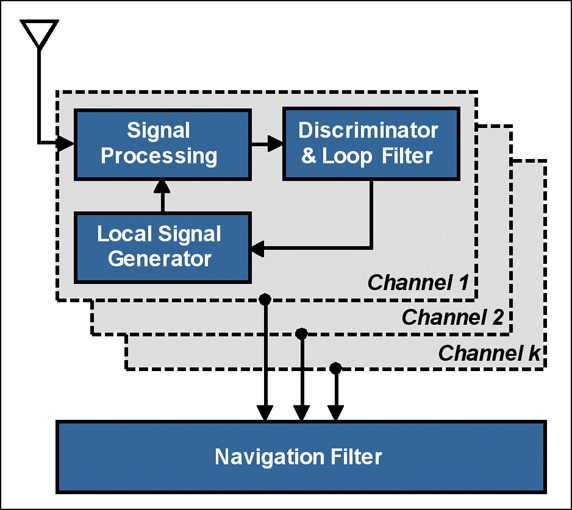
The standard (scalar-tracking) GNSS receiver architecture is shown in Figure 1. In the context of this article, the key characteristic of a standard receiver is that the signals from the different satellites are each tracked in parallel and independent tracking channels, and usually only three correlators are used. The information from the channels is only combined in the navigation filter to estimate position, velocity, and time. In this way, there is no sharing of information between channels in order to attempt to improve tracking performance.
Figure 1. Standard receiver architecture (courtesy Petovello et al).
Within each channel, the down-converted and filtered samples from the front end (not shown in Figure 1) are then passed to a signal-processing function where Doppler-removal (baseband mixing) and correlation (de-spreading) is performed. The correlator outputs are then passed to an error-determination function consisting of discriminators (typically one for code, frequency, and phase) and loop filters. The loop filters aim to remove noise from the discriminator outputs without affecting the desired signal. Finally, the local signal generators — whose output is used during Doppler removal and correlation — are updated using the loop-filter output.
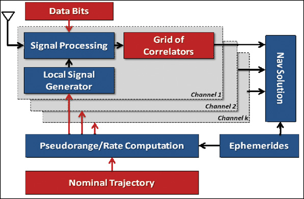
Assisted HS GNSS Receiver. The assisted HS GNSS receiver architecture used in this work is shown in Figure 2. Notable differences to the standard receiver architecture are highlighted in red.
Assistance information is provided in the form of broadcast ephemerides, raw data bits, and a nominal trajectory (position and velocity) that would normally be generated by the receiver. At each measurement epoch, the receiver uses the nominal position and velocity in conjunction with the ephemerides to compute the nominal pseudorange and pseudorange rate for each satellite in view. These parameters are passed to the signal-processing channels. Each channel evaluates a grid of correlators around the nominal pseudorange (code) and pseudorange rate (Doppler) values. The data bits are wiped off using the assistance information to permit long coherent integration times. For each signal tracked, the correlator grid is used to estimate code and Doppler offsets relative to the nominal values. These estimates are then used to generate accurate pseudorange and Doppler estimates.
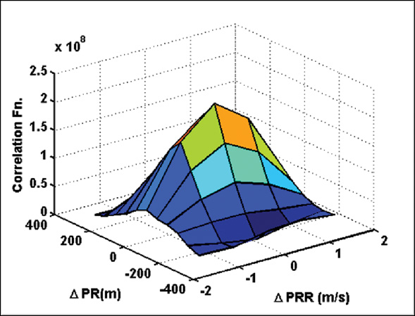
The number of correlators used and the spacing of these correlators in the code and frequency domains are completely configurable. A sample correlation grid computed during live data processing is illustrated in Figure 3. Measurements are generated by choosing the three correlators nearest the peak in the search space and using a quadratic fit to determine a better estimate of the peak location. In this work, a total of 55 correlators per channel were used.
Figure 3. Sample grid of correlator points computed for GPS PRN 04.
The assisted HS receiver is initialized in static mode in an open-sky setting during which reliable clock bias and drift estimates are derived. A high-quality oven-controlled crystal oscillator was used during this initial test to ensure that the clock drift did not change significantly over the period of the test (approximately 20 minutes). The clock bias during the test is updated using the clock drift estimate.
Note that this architecture is a generalization of the vector-based architecture, where the navigation solution used to aid the signal processing can be provided by an external reference.
Navigation Solution Processing. All navigation solution results presented here are obtained in single-point mode using an epoch-by-epoch least-squares solution with the PLAN Group C3NavG2 software, which uses both code and Doppler measurements. This processing strategy enables a fair comparison amongst the different signal processing strategies, as the smoothing effect of specific navigation filters is eliminated by this approach. More realistic accuracy estimates of the measured pseudoranges can be obtained. It is understood that in an operational environment, a well-tuned filter will obtain significantly better navigation performance than the epoch-by-epoch solutions presented here.
The measurements are weighted using a standard-elevation-dependent scheme. Thus there is no attempt to tune the weighting scheme for each receiver.
Data Collection
To test the relative performance of the various processing strategies, we conducted a test in downtown Calgary. Data was collected using a commercial HS GPS receiver, a commercial survey grade GPS/GLONASS receiver, and an RF downconverter and digitizer. The digitized data was post-processed in two modes (standard and assisted HS GNSS) using the PLAN group software receiver GSNRx.
Raw measurements were logged from each of the commercial receivers at a 1-second interval. The parameters used in GSNRx are given in Table 1.
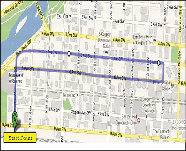
The trajectory followed is shown in Figure 4. The majority of the route was travelled in an East-West direction, with significant signal masking to the North and South. The Opening Photo shows an aerial view of downtown Calgary where the test took place. Masking angles exceeded 75 degrees along the vehicle trajectory.
Figure 4. Test Trajectory where the route is approximately 4 km with a 10 minute travel time.
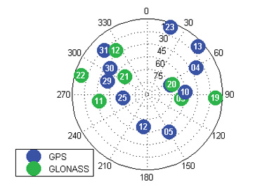
A sky plot of the satellites visible above a 5-degree elevation mask at the test location is shown in Figure 5. A total of 11 GPS and seven GLONASS satellites were present.
Figure 5. Skyplot of GPS and GLONASS satellites over Calgary at the start of the test.
A static period of approximately three minutes duration was used to initialize the assisted HS GNSS processing. During this period, the vehicle had a largely clear view of the sky. Nevertheless, three satellites were blocked from view during this period, namely GPS SVs 13 and 3, and GLONASS SV 22. As a result, these SVs were not available for processing in the assisted HS GNSS mode. The two commercial receivers were already up and running prior to the initialization period and so were able to process these three low-elevation satellites when they came into view during the test. See PHOTO on next page for a typical scene during the downtown test.
Analysis
To study the impact of adding GLONASS, the analysis focuses on solution availability, the number of satellites used in each solution, the DOP associated with each solution, and the statistics of the least-squares solution residuals. In the absence of a reference solution, the statistics of the residuals nevertheless give a reasonable indication of the quality of the measurements used, provided sufficient measurements are available to ensure redundancy in the solution. Nevertheless, some pseudorange errors will be absorbed by the navigation solution, hence the statistics of the residuals can be viewed as only a good estimate of the quality of the measurements themselves.
Solution Availability. As previously discussed, the navigation processing strategy adopted is the same for all receivers used in the test. A single-point epoch-by-epoch least-squares solution is computed at a 1 Hz rate. If there are insufficient satellites in view at a given epoch, or the solution fails to converge in 10 iterations, no solution is computed. In this section, the analysis focuses on the percentage of epochs during the downtown portion of the test for which a solution was computed.
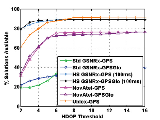
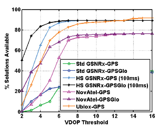
Figure 6 shows the percentage of solutions computed for each receiver processing strategy as a function of HDOP and VDOP thresholds, respectively. Thus, for example, the assisted HS GPS-GLONASS processing strategy yielded navigation solutions with a HDOP less than 6 between 80 percent and 85 percent of the time. For larger DOP thresholds, it is clear that there is little difference between GPS-only processing and GPS+GLONASS processing. The biggest differences are caused by the processing strategies employed. The advantages of HS processing are clear, at least in terms of solution availability. For this test and the particular geometry of the satellites in view during the test, GPS+GLONASS processing does yield a noticeable improvement in the VDOP, particularly at lower thresholds.
Figure 6A. Percentage solution availability versus HDOP threshold.Figure 6B. Percentage solution availability versus VDOP threshold.
Note that the standalone HS GPS receiver exhibits greater solution availability than the assisted software HS GPS-GLONASS receiver at higher DOP thresholds. This is most likely due to the low-elevation satellites that were excluded from the assisted HS processing due to their being masked during the initialization period as discussed earlier. Overall, however, there is little difference between GPS-only processing and GPS-GLONASS processing in terms of solution availability. This fact, of course, does not yield any information on the quality of the solutions obtained, which is discussed later.
To gain further insight into the impact of GLONASS, Figure 7 shows the percentage of solutions computed that exhibit redundancy. Thus, of all solutions computed during the downtown portion of the test, Figure 7 illustrates the percentage of those solutions that have redundant measurements. For GPS-only processing, this implies that five or more measurements were used in computing the position, while for GPS-GLONASS processing a minimum of six measurements were required. In this case, the advantage of using GLONASS becomes more apparent. For all processing strategies the addition of GLONASS yields an increase of 5 to 10 percent in the number of solutions with redundancy. Although not studied herein, this would have a positive impact on fault detection.
Residuals Analysis
To investigate the quality of the measurements generated by each processing strategy, the residuals from the least-squares solutions are studied. Only those epochs for which redundant solutions are computed are considered here, since non-redundant solutions lead to residuals with values of zero. As discussed above, the analysis of these residuals gives an estimate of the quality of the measurements generated.
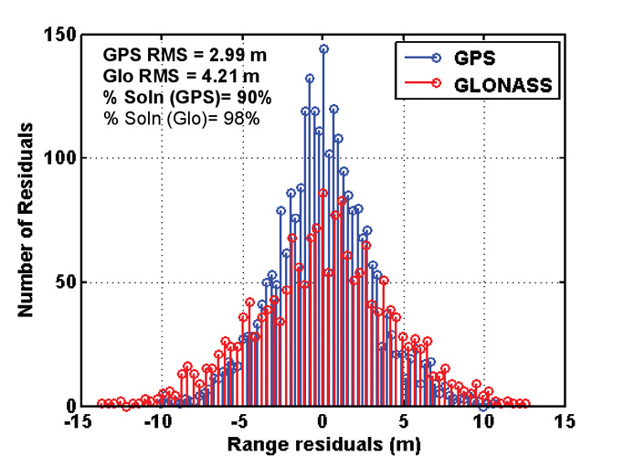
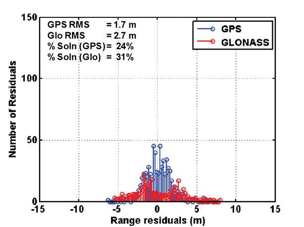
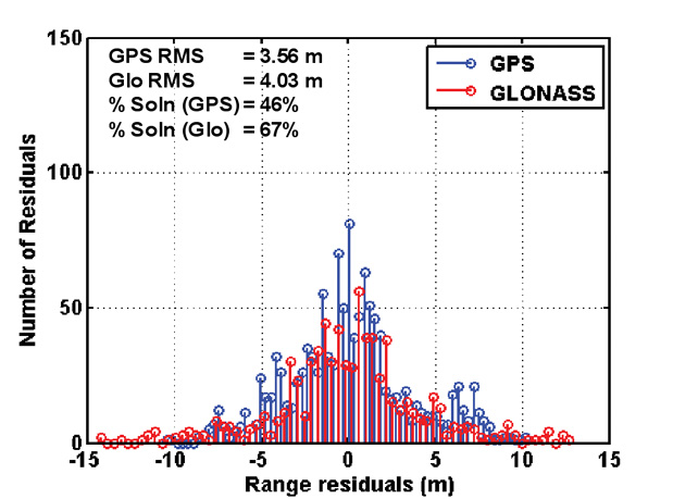
Figure 8 shows the histograms of the residuals from all GPS-GLONASS processing strategies. Once again, it is important to emphasize that only residuals from solutions with redundancy are considered. In addition, the results presented are limited to those epochs during which the vehicle was in the downtown portion of the test. For the purposes of this presentation an upper GDOP threshold of 10 was set.
It is interesting to note that in all cases (assisted HS, standard wide correlator, and commercial survey-grade processing), the relative RMS values of the GPS and GLONASS residuals are about the same. These results indicate that, irrespective of the signal-processing strategy employed, the GLONASS measurements are of a similar quality to the GPS measurements. The number of residuals available is however different between the standard and HS solutions, as the latter produce more measurements and more redundant solutions, hence more residuals. The processing strategy obviously had a significant impact on the availability of redundant solutions as discussed in the previous section.
Figure 8A. GPS-GLONASS range residuals comparison: assisted HS-GPS-GLONASS. RMS values and the percentage of solutions used in the histogram are also shown.Figure 8B. GPS-GLONASS range residuals comparison: standard wide correlator. RMS values and the percentage of solutions used in the histogram are also shown.Figure 8C. GPS-GLONASS range residuals comparison: survey-grade receiver. RMS values and the percentage of solutions used in the histogram are also shown.
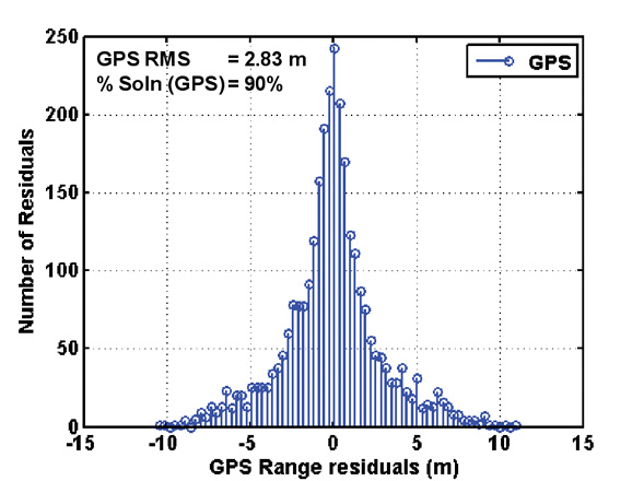
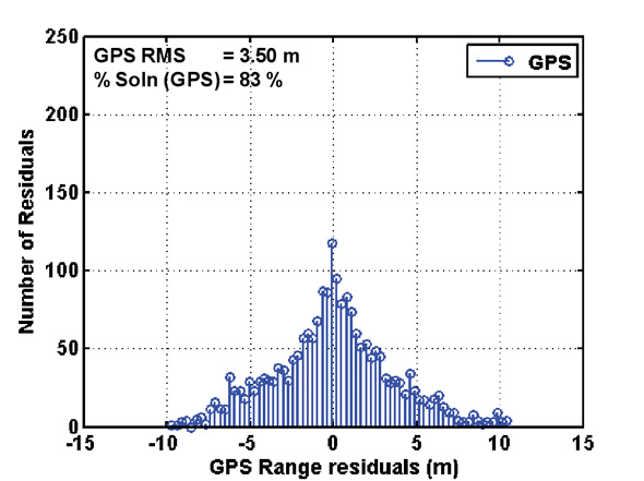
Figure 9 shows the histograms of the range residuals from GPS-only processing. In this case, the navigation solution is a GPS-only navigation solution, though in the case of the assisted HS receiver the measurements used are identical to those used in Figure 8.
Clearly the assisted HS receiver has a greater availability of redundant solutions compared to the standalone receiver, which is to be expected. Also, the assisted HS GPS receiver residuals have a slighter lower RMS than when a GPS-GLONASS implementation was considered, indicating that the navigation solution absorbs more of the measurement errors in this case.
Figure 9A. GPS range residuals comparison, assisted HS GPS.Figure 9B. GPS range residuals comparison, commercial standalone HS GPS.
Position Domain Results
The final stage of the analysis is a comparison of the trajectories computed using each of the receiver types. While no truth solution was available for this test, a highly filtered navigation solution from the high-sensitivity commercial receiver was used as a nominal reference. This trajectory is shown in black in the following figures.
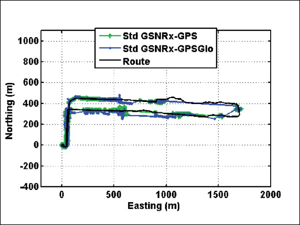
Figure 10 shows the trajectories obtained using standard wide-correlator processing. The position solutions are quite accurate, but the availability is low, namely of the order of 30 percent as shown above. The addition of GLONASS does improve the availability in this case. The accuracy is not significantly improved. In fact it appears that the addition of GLONASS occasionally leads to biases in the navigation solutions, likely solutions with high DOP values.
Figure 10. Trajectory obtained with standard wide correlator processing.
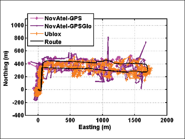
Figure 11 shows the trajectories computed using the commercial receivers. The survey-grade receiver yields less noisy positions, though the addition of GLONASS does lead to some significant outliers. The position availability is lower as discussed earlier. Similar to the standard wide-correlator processing case, the addition of GLONASS again appears to introduce an error in the solution during some epochs (for example, at a northing of about 500 meters between 100 and 500 meters easting).
Figure 11. Trajectories obtained from the commercial receivers.
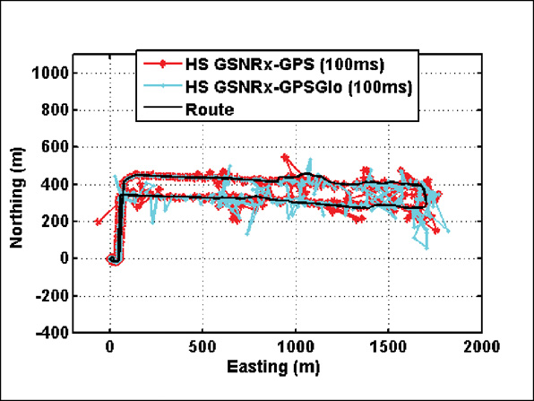
Finally, Figure 12 shows the trajectories obtained from the assisted HS receiver. In this case, the position solutions are significantly less noisy than in previous cases, in addition to being more available. The quality of the GPS-only and GPS+GLONASS results is broadly similar, with perhaps more outliers in the GPS-GLONASS case, due to the reason mentioned earlier.
Figure 12. Trajectories obtained using assisted HS GPS-GLONASS processing.
In summary, it would appear that the greatest benefit of GLONASS in this test was in the provision of greater redundancy in the navigation solution, in addition to potential better reliability, although the latter remains to be confirmed. With GLONASS approaching full operational capability, it is to be expected that the increased GLONASS constellation will lead to further improvements in terms of availability, DOP, and reliability.
Coherent Integration Time
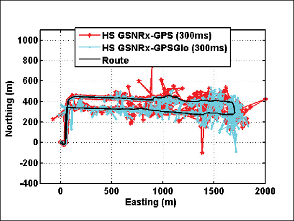
From the preceding analysis it is clear that the assisted HS GNSS processing strategy yielded the best performance. To evaluate the impact of the coherent integration time on performance, the data was re-processed with a coherent integration time of 300 milliseconds (ms), instead of the 100 ms used for the data presented so far. The resulting trajectories are shown in Figure 13.
It is interesting to note that increasing the receiver sensitivity in this way does not yield better navigation performance. In fact, in the urban canyon environment, the major issue is not the signal attenuation (which can be overcome by increased coherent integration) but rather the multipath effect. By increasing the coherent integration time to 300 ms, the receiver becomes more sensitive to dynamics, resulting in poorer navigation performance.
Figure 13. Trajectories obtained using assisted HS GPS-GLONASS processing (300 ms integration time).
Discussion
High-sensitivity processing in urban canyon environments is a very effective means of improving navigation performance. Given the discussion above, however, it is clear that the performance is not limited by the strength of the received signal, but rather by the effect of multipath and satellite geometry.
The advantage of high-sensitivity processing in this case is two-fold. The first advantage over standard tracking techniques is the open-loop nature of HS processing. The time-varying nature of the multipath channel causes significant variation in signal level. This variation can cause traditional tracking loops to lose lock. In fact, the poor performance of the standard wide-correlator strategy in the above analysis can be explained by the fact that the receiver was unable to maintain lock on the satellites in view. Hence no measurements were generated, and no solutions computed. The survey-grade receiver used has advanced multipath mitigation technology, which helped to avoid loss of lock, but may have been tracking non-line-of-sight signals during portion of the down-town test, leading to errors in the navigation solution.
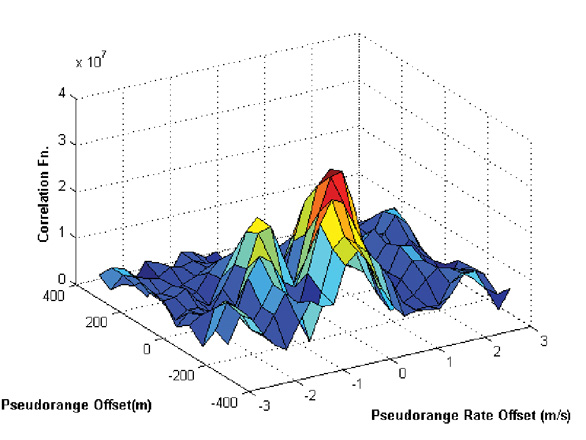
The second advantage of HS processing is related to the coherent integration time and the vehicle dynamics. As the receiver antenna moves through the multipath environment, a different Doppler shift is observed on signals coming from different directions. Thus the line-of-sight and multipath components become separated in frequency. A longer coherent integration time increases the frequency resolution of the correlator output (due to the familiar sinc shape). Thus if the line-of-sight is present, and the coherent integration time is long relative to the inverse of the Doppler difference between the line-of-sight and reflected signals, individual peaks become visible in the grid of correlators. This effect can significantly reduce the impact of multipath on the measurements. Figure 14 gives an example of this.
Figure 14. Sample correlation function showing two peaks.
Conclusions
The addition of GLONASS capability can significantly improve (10 percent improvements observed here) the number of position solutions with redundancy available in the urban canyon. With increasing GLONASS satellite availability, the benefits of using GLONASS will even be greater. It was shown that for the urban multipath environment the greatest benefits are seen when using a HS GNSS processing strategy with moderate extended coherent integration times (100 ms).
Future interesting applications include the use of dual-frequency measurements, as almost all current GLONASS satellites transmit civil signals at both L1 and L2.
Acknowledgments
The authors would like to kindly acknowledge and thank Defence Research and Development Canada (DRDC) for partly funding this work.
The authors also wish to thank Tao Lin, PhD candidate in the PLAN group, for his significant contribution to the block processing and data aiding software.
Manufacturers
The tests used a National Instruments PXI-5661 RF downconverter and digitizer, the PLAN GSNRx as standard wide-correlator receiver, the u-blox Antaris 4 (standalone HS-GPS), NovAtel OEMV-3 (survey-grade GPS/GLONASS), and the PLAN group software receiver GSNRx, as the assisted HS GPS/GLONASS.
Cillian O’Driscoll received his Ph.D. in 2007 from the Department of Electrical and Electronic Engineering, University College Cork, and is currently a post-doctoral fellow in the PLAN Group of the University of Calgary.
Gérard Lachapelle is a professor of geomatics engineering at the University of Calgary where he holds a Canada Research Chair in wireless location and heads the Position, Location and Navigation (PLAN) Group.
Mohamed Tamazin is a M.Sc. candidate in the the PLAN at the University of Calgary. He holds a M.Sc. in electrical communications from the Arab Academy for Science and Technology, Alexandria, Egypt.
In my last issue, I proclaimed the start of GPS/GIS month, with a focus on the subject in three of my newsletters. This is the second in that series. The first column can be read here. Also, I’m hosting a webinar June 30 to discuss using GPS receivers and technology for GIS data collection. In my last newsletter I discussed the use of consumer GPS receivers for GIS data collection. Remember the analogy I used…a Volkswagen Beetle wasn’t designed to run in a Formula One race? This column is going to focus on the Formula One cars, not the Volkswagen Beetles. In other words, it will focus on the GPS receivers on the market that are designed for GIS data collection. I will refer to them as GPS/GIS receivers.
What differentiates a GPS/GIS receiver from any other GPS receiver?
The number-one differentiator is that GPS/GIS receivers are designed do a better job of optimizing tracking and accuracy in areas where GIS data collection is performed. The operative term is “are designed.” Specifically, engineers who designed GPS/GIS receivers do so with different design criteria than engineers who design consumer GPS receivers and even survey GPS receivers. For example, a GPS/GIS receiver must be designed to operate where GIS data is collected and with reasonable accuracy. On the other hand, consumer GPS receivers are designed to track in tough conditions, but at the expense of accuracy. Furthermore, survey GPS receivers hold accuracy as the number-one priority so they sacrifice the ability to track in many environments.
The following matrix illustrates my point (1 = Highest priority design consideration, 5 = Lowest priority design consideration):
There are thousands of designers of consumer GPS receivers (Garmin, TomTom, Magellan, etc.) and probably only 10 designers of GPS receivers for surveying (Trimble, Leica/NovAtel, Topcon, Magellan Professional, Septentrio, JAVAD GNSS, NavCom, etc.). There are even fewer designers of GPS/GIS receivers — less than 10 (Trimble, Magellan Professional, Topcon, Geneq, Sokkia, Hemisphere, JAVAD GNSS, ViaSat).
The market for GPS/GIS receivers is a complicated one. That’s the primary reason why there are only a few manufacturers. Here are some of the reasons why it is complex:
Users require a GPS receiver that will work effectively in many different and challenging environments such as under trees, in mountainous areas and near buildings. There is not one product on the market that will meet every user’s requirements.
Users have various needs for the type of GIS data collected. For example, some only need two or three attributes for a utility pole and others may need to collect dynamic line segments such as speed zones and road lane types.
There is not an effective way for manufacturers to distribute such products. The traditional survey instrument dealers (not all) are not typically trained or experienced in GPS/GIS technology. Since there is not an effective distribution channel, the alternative is to create a grass-roots distribution channel, which is very time-consuming.
There are many factors to consider when attempting to determine what sort of GPS/GIS data collection system best fits a user’s requirements. Here are some in order of priority:
Budget. One could argue that data collection requirements should be #1. Maybe, but that depends on what stage of planning you’re in. If you are in the budget planning phase and are able to influence it, then I agree that user requirements should be the first priority. However, the vast majority of people I encounter are given an established budget to work within. In that case, budget should be #1 because it’s a waste of time to consider solutions outside of the budget constraint.
Accuracy. When I ask a potential GPS/GIS user what their accuracy requirement is, the typical answer is “as accurate as I can get”. Of course, you can imagine the ensuing conversation…Me: Well, Ok, you can achieve results around a centimeter. Them: That’s great. A centimeter is perfect. Me: Ok, here are the cost and training requirements. Them: Wow, why is it so expensive??????? Me: There is a direct relationship between accuracy and cost. The more accurate you want, the more expensive it’s going to be. Them: Well, Ok, we reeeeally only need to be within about three feet. Me: Do you need elevation values within three feet? Them (now leery of the response to their answers): Will those cost more? Me: Yes, probably quite a bit more. Them: No, we don’t need elevations.
Data collection requirements. Essentially, consumer GPS receivers and survey GPS systems “think” in terms of points. More specifically, consumer GPS receivers operate in terms of waypoints and survey GPS systems operate in terms of point averaging.
Some of the more sophisticated survey GPS systems offer Field-to-Finish (F2F) capability whereas points are automatically connected to form a line back in the office such as with curbs and property lines.GIS data collection systems are different. GIS “sees” the world in one of three ways; points, lines (or polylines) and areas (or polygons). All have some level of database information attached. For example, a fire hydrant is a point on a map but there is also information in the GIS about that fire hydrant such as condition, last inspection date, etc. A parcel is a polygon on a map but there is also information in the GIS about that parcel such as ownership, tax id, etc.
Additionally, there are several methods to record all three.For example, a wetland biologist may be mapping the perimeter of a wetland area but wants to “take points” on certain habitat nests he/she sees while walking the perimeter. Some of the more powerful GIS data collection software is built so the biologist can temporarily suspend mapping the perimeter and be allowed to map the next site and resume mapping the perimeter when point recording is finished.
Using the proper data collection software that matches the user requirements can save a significant amount of time and energy.
Data collection conditions. This is the biggest “gotcha” for GPS/GIS receivers. A certain GPS receiver designed for GIS data collection may perform flawlessly in the open-sky and works perfectly well for uses such as agriculture or other open-sky environments. However, most uses consist of some or all work done in “less-than-ideal” GPS conditions. Tree canopy is the biggest culprit. In that scenario, receiver performance can differ significantly. Some won’t track at all in those environments and some will track very well, but accept excessively noisy satellite measurements (which significantly degrades accuracy). The best ones are designed with a keen balance of satellite tracking and accuracy – with settings the user can change depending on the environment.
Why are GPS/GIS receivers so much more expensive than consumer GPS receivers?
Part of the reason that consumer GPS receivers are adapted to GPS/GIS data collection is the significant difference in cost. A consumer GPS receive
r can be purchased for well under US$200. The entry level price for a GPS receiver with comparable accuracy, but with GIS data collection features is four times that. Furthermore, the entry level price for a GPS/GIS receiver capable of sub-meter accuracy is about $2,000.
There are several specific and justifiable reasons for the price difference, but suffice to say that significantly more design engineering, technical support and sales effort is involved with GPS/GIS receivers. Furthermore, the volume of GPS/GIS receivers is miniscule compared to consumer receivers. If there were tens of millions of GPS/GIS receivers manufactured and sold every year, the price would be under US$200 each. But the GIS market just isn’t that large. Therefore, GPS/GIS manufacturers have to charge more per unit to account for engineering, technical support and sales overhead.
Lastly, as mentioned above, there are not very many manufacturers of GPS/GIS receivers. Lack of competition usually results in higher prices to the end user.
What sources of GPS corrections are available?
Autonomous (no differential correction applied) GPS is pretty accurate these days…on the order of a few meters. For this reason, consumer GPS receiver manufacturers tend to leave out information on GPS corrections in their specifications. Their rationale is that consumers don’t really care as long as they can navigate effectively.
However, the GPS/GIS receiver market is much more concerned with accuracy. Therefore, some sort of GPS correction source is highly recommended and necessary to achieve the desired accuracy.
There are essentially two types of GPS corrections: real-time and post-processing.
Throughout the 1980s and 1990s, post-processing was the dominant method of correcting GPS data. Even then, 2-5 meter accuracy was the norm for GPS/GIS receivers after post-processing was applied. Sub-meter GPS technology (using GPS/GIS receivers) only became possible towards the end of the 1990’s. Users were accustomed to going through the post-processing exercise (downloading base station data, QAing post-processed data, etc.). At that time, the only option for using real-time corrections were commercial services such as OmniSTAR.
In the mid-1990s, the U.S. Coast Guard (USCG) established the DGPS system that broadcast real-time GPS corrections free of charge along the US coastlines and major waterways. The user only needed to purchase equipment (beacon receiver) to receive the signal. The success of that program lead to the U.S. Department of Transportation (DOT) to expand the program to cover inland regions that were out of the USCG domain. That was the GPS/GIS user’s first taste of free DGPS corrections…and they liked it because it eliminated the time-consuming (and sometimes painful) process of post-processing.
The break-out milestone for real-time corrections came in 2003 when the Federal Aviation Administration (FAA) declared the Wide Area Augmentation System (WAAS) operational. WAAS took real-time GPS corrections to another level of simplicity. Not only is WAAS free of charge to users, but unlike the USCG DGPS and commercial DGPS services, it’s broadcast on the same frequency as GPS. This means that no extra antenna or receiver is required to utilize the signal. Furthermore, it’s broadcast nation-wide in the US where ever the WAAS satellites are visible to the user. Due to the success of WAAS, several other regions in the world have deployed similar systems; EGNOS in Western Europe, MSAS in Japan/Korea and GAGAN in India.
Finally, in the early part of this decade, local networks of reference stations began springing up. These are called RTK Networks. While built primarily for users of survey GPS receivers who require cm-level accuracy, there is a growing population of GPS/GIS users who are connecting their GPS/GIS receivers to these networks to obtain GPS corrections. However, the costs can be expensive. Some network operators charge a fee to access their network and the user must also have a data subscription with a wireless provider (GSM or CDMA) which has a monthly fee associated with it — similar to a mobile phone.
The Future is Clear
The trend is clearly towards using real-time GPS corrections no matter which source is used. The time consumed by post-processing and the expense of maintaining software and training requirements adds too much overhead in most applications for organizations to consider it.Although not the dominate correction technology any longer, post-processing in the GPS/GIS segment still has a niche – the so-called “sub-foot” niche. While the majority of GIS applications are satisfied with “sub-meter” (or even 1-3 meter) accuracy, there are certain applications where “sub-foot” accuracy is required. With these receivers, the users must post-process against several reference stations or tie into an RTK Network.
Integrated “All-in-one” GPS/GIS receiver or separate stand-alone receiver?
In the GPS/GIS receiver market, there are clearly two types of systems. The “All-in-one” receivers have the GPS receiver, antenna and data collector built into a hand-held format. These are products such as the Trimble GeoXT/XH, Magellan Mobile Mapper CX/6 and Topcon GMS-2.
The “stand-alone” receivers are a “black box” which houses only the GPS receiver, GPS antenna and optionally a battery. Other devices such as PDAs, tablet computers and notebook computers receive GPS data from these stand-alone receivers typically via Bluetooth interface or cable connection. These are products such as the Trimble ProXT/XH, Geneq SX Blue, Sokkia GIR1600, Hemisphere A100 and Javad GISMore.
There are advantages and disadvantages to both.
“All-in-one” receivers house everything one needs in a single hand-held unit. The advantage is that the data collector, GPS receiver, antenna, battery system, etc. are all designed by one company to work together. On the other hand, designing all of these components into a single hand-held can make for a somewhat heavier unit. Also, PDA technology is evolving rapidly. “All-in-one” receivers aren’t updated nearly as fast as PDA technology so an “All-in-one” unit may have an out-dated operating system and/or processor if the design is a few years old.
“Stand-alone” receivers are separate receivers that send GPS data to a PDA, tablet computer or notebook computer via wireless Bluetooth or cable connectio
n. The advantage of these systems is flexibility. On one project, they can be interfaced to a PDA. On the next project, they can be interfaced to a notebook computer running different mapping software. They aren’t affected by the advancement of PDA, operating system or computer processor technology.
The Final Analysis — GPS/GIS Receivers for GIS Data Collection
There a myriad of GPS receiver technologies being used for GIS data collection. It’s a complex industry. Some receivers being used are purpose-built and others have been adapted from other industries like consumer GPS.
There is no magic formula to determine which GPS receiver will work best because it really depends on the user’s requirements and in GIS, the user requirement vary greatly. “Try before you buy” is the best advice to follow when going through the equipment/software selection process.
If you have time, I’m conducting a GPS/GIS receiver webinar on June 30 (next Tuesday) at 10:00 a.m. Pacific time. I will continue the discussion of GPS/GIS receiver selection. Register for the webinar here.
Consumer-Grade GPS Receivers for GIS Data Collection
I hereby proclaim June GPS/GIS month (at least for me). I’m dedicating the next three newsletter columns (early June, mid-June, and early July) and a webinar (June 30) to discussing using GPS receivers and technology for GIS (geographic information systems) data collection. Why, you may ask?
First of all, I realize my domain is typically the high-precision survey/construction arena, but the boundary isn’t so clear cut any longer. Many surveyors, engineers and construction crews use less accurate GPS receivers for activities such as GIS data collection, recon, and navigating — so the topic is relevant.
Secondly, ’tis the season. The ESRI User Conference is in mid-July this year — about six weeks from now. Although high-precision GPS has a firm place there and is growing, the ESRI UC is the largest conference in the world where non-survey GPS is near center stage. It is one of the primary data-gathering tools that fuels a GIS.
There have been some really significant changes in the last 10 years. GPS data-collection tools for GIS have expanded. At that time, consumer receivers couldn’t be used because Selective Availability (SA), the intentional degradation of GPS accuracy by the Department of Defense, was still active. Also, “submeter” GPS mapping systems were backpack-based, contained a “rat’s nest” of cables, required camcorder batteries to run, and were generally bulky. Data collectors were based on DOS instead of Windows. Lastly, users were primarily using post-processing to differentially correct their GPS data or using Marine DGPS/NDGPS in select locations or commercial DGPS services like OmniSTAR for real-time DGPS.
Fast forward to today. Three categories of GPS are being used to populate GIS databases: consumer-grade receivers, GPS receivers designed specifically for GIS data collection, and survey receivers used for GIS data collection. In this column, I’ll discuss using consumer-grade receivers for GIS data collection. In my mid-June column, I’ll discuss the class of GPS receivers designed specifically for GIS data collection.
Consumer-Grade Receivers
Overnight, when SA was turned off in May 2000, consumer-grade GPS receivers became a viable option for GIS data collection where accuracy is not of the highest priority. Today, due to improvements to the GPS itself as well as GPS receiver technology and along with the maturation of WAAS/SBAS, consumer-grade GPS accuracy is even better.
Thousands, maybe tens of thousands, of consumer-grade GPS receivers are being used to collect data used for GIS. They are easy to use and the price is attractive.
Understanding the accuracy of a consumer-grade GPS receiver is not a simple task. In fact, if you’re not careful, you can be easily misled. For example, take a receiver out to the parking lot and wait for it to obtain enough satellites and a WAAS/SBAS correction. You may be impressed with its precision as it might be within a couple of meters or even better. There are two issues with this:
Repeatability…accuracy vs. precision. Precision is a group of points that are tightly clustered but not in the right place. For example, you may have a cluster of 10 points all within two meters of each other, but they are five meters from the true location. This is not necessarily desirable, but quite typical for consumer-grade GPS receivers. Some receivers offer an “EPE” (Estimated Positional Error) value on the display to provide you and indication of accuracy. Absolutely do not rely on this value in an attempt to estimate the position accuracy of the receiver. It is a rough guess at best.
Performance in less-than-desirable GPS conditions. Surprisingly, or not, users assume that performance in a grove of trees is going to be similar to performance in a parking lot with a wide open view of the sky. This is not the case.
I’ll give you a real case study. Several years ago I was helping a company setup a GPS system to map utility poles. Their required accuracy was +/- 3 meters. A local survey equipment salesperson suggested they use a consumer-grade Compact Flash (CF) GPS receiver plugged into the top of a ruggedized PDA. The salesperson demonstrated the receiver in the client’s parking lot. The performance, in the client’s eyes, seemed like it would meet the +/- 3 meter requirement. The price was right at $250 per receiver and they need upwards of 15 receivers. There were a couple of alternative proposals that cost significantly higher per receiver ($2,000-$4,500 each). The price difference was too great for the client not to be tempted to try the $250 receiver so they purchased six of them. They ended up using them for only 60 days. The bottom line was that the receiver performed very poorly in the field in two areas. First, many of the utility poles were located in areas where there were many trees. The client found that the CF GPS receiver performed very poorly in that environment. Some positions were off by more than 50 meters. Secondly, the client found that the CF GPS receiver had a difficult time maintaining lock on the WAAS satellites used for corrections even in relatively wide open areas where this shouldn’t have been a problem.
In this case, the lesson is to try the receiver in an environment where you will be using it. All GPS receivers will perform worse under tree canopy as compared to their performance in an open area. This is the Achilles heel of GPS. That being said, some GPS receivers perform better under tree canopy than others. The ones that do perform better under trees were designed to do so. Using a consumer-grade GPS in that environment is sort of like trying to compete in a Formula One race with a Volkswagen Beetle. The design criteria of the Beetle was fuel economy and low cost, not acceleration and cornering. The same applies to consumer GPS receivers. Accuracy is not one of the top criteria for consumer GPS receiver designers. They are much more concerned with low cost, low power consumption, small antenna size and fast satellite acquisition, as they should be. My wife, for example, really doesn’t care if it’s accurate to 15 meters vs. 1 meter as long as she arrives at the destination she plugs into the system. On the other hand, high-performance GPS receivers designed for GIS data collection sacrifice some features such as power consumption, antenna size, and small size in order to optimize accuracy.
This is not to say that consumer GPS receivers have no place in GIS mapping. On the contrary, they have a very important place. My point is that your expectations should match reality when evaluating receivers to use for your project. The accuracy specifications on consumer GPS receiver datasheets are essentially meaningless. The only way to truly understand the performance of a particular receiver is to try it yourself.
One final note on this. Many commercial (typically survey equipment dealers) and academic entities have published accuracy comparisons of different consumer GPS receivers. You really have to take these reports with a grain of salt. Sometimes the reports are intentionally biased and other times they are biased due to lack of knowledge or experience. They are also based on an environment that may not be similar to yours. “Heavy” tree canopy is a subjective term. Tree canopy in Oregon is different than tree canopy in Alberta and is different from tree canopy in Austria.
The Final Analysis
Upside:
Low cost
low power
user-friendly
small
Downside:
Poor accuracy in challenging GPS conditions
inconsistent accuracy in non-challenging GPS conditions